

Page 1
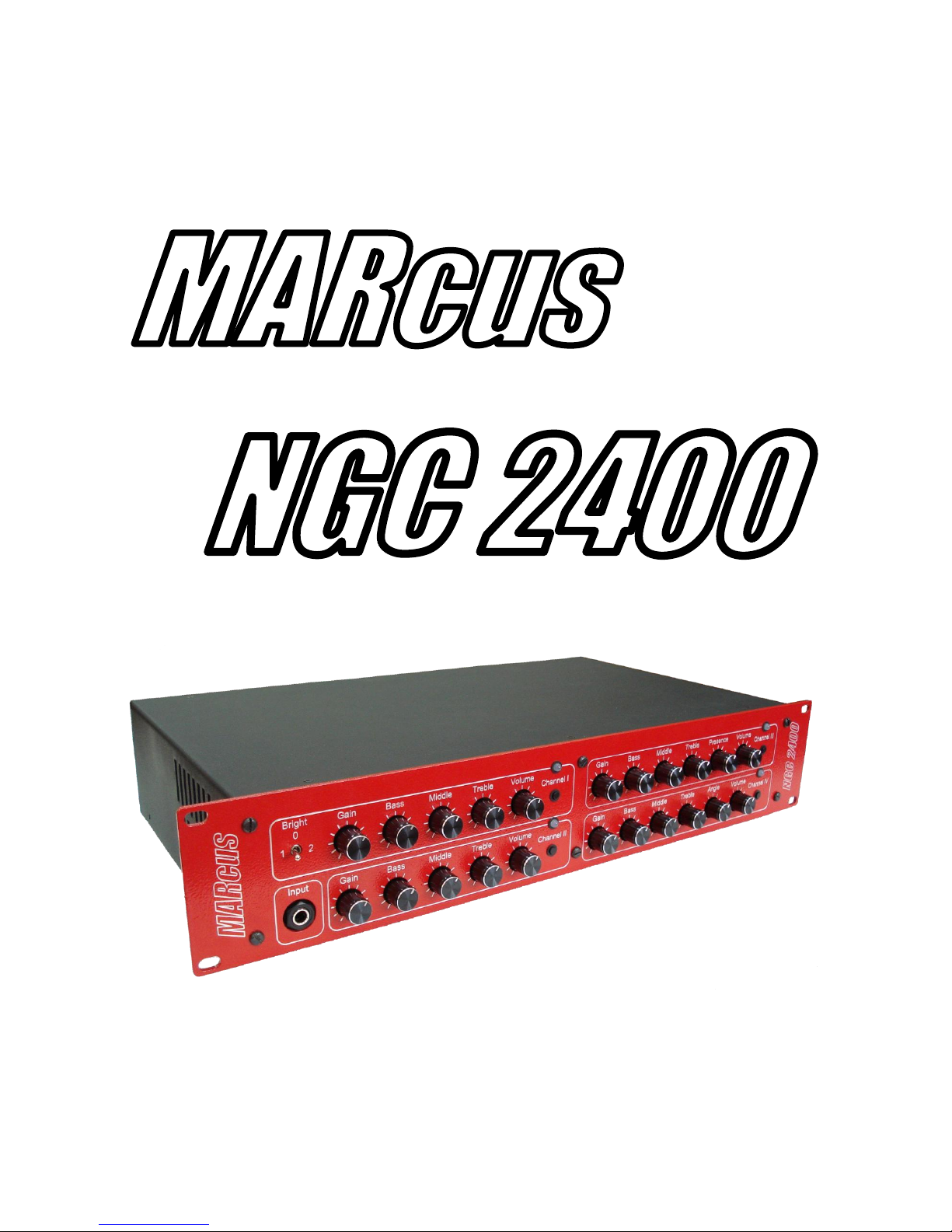
Guitar tube preamplifier
User’s Guide
Page 2

MARcus NGC 2400 User’s Guide
1
CONTENTS
Forward………………………………………………….……...2
Technical specifications……………………………………..3
Front panel……………………………………………………..4
Rear panel………………………………………………………5
Warnings………………………………………………………..6
Page 3

MARcus NGC 2400 User’s Guide
2
FORWARD
MARcus NGC 2400 is custom built all-tube guitar preamplifier which
has totally separated four channels with unique sounding, seven tubes
12AX7, two outputs – “Direct” and “Record”, speaker-simulator 4x12 and
Master Volume. Harmonically reach and widely applied sound is a great
advantage of this preamp. Each channel can have custom options if it is
necessary. It can be used on the stage as well as in studio application having
switching knobs on the front panel and a footswitch. Standard 2U mounting
and remarkable front panel allow making any rack gear more significant and
multipurpose.
CONGRATULATION FOR YOUR CHOICE!
Page 4

MARcus NGC 2400 User’s Guide
3
TECHNICAL SPECIFICATION
Channels: 4
Channel I (Green) – Clean (Fender®Twin)
Channel II (Blue) – Crunch (Marshall® JCM800)
Channel III (Yellow) – High gain 1 (Bogner® Ecstasy)
Channel IV (Red) – High gain 2 (Mesa/Boogie® Rectifier)
Controls: separated for each channel
Channel I – BRIGHT switch GAIN BASS MIDDLE TREBLE VOLUME
Channel II – GAIN BASS MIDDLE TREBLE VOLUME
Channel III – GAIN BASS MIDDLE TREBLE PRESENCE VOLUME
Channel IV – GAIN BASS MIDDLE TREBLE ANGLE VOLUME
MASTER VOLUME
Outputs: 2
DIRECT mono output
RECORD stereo output
Switching:
separated for each channel switch knobs on front panel
6-pin DIN footswitch
Tubes: 6 x 12AX7EH and 1 x 12AX7WA
Input impedance: 1 MOhm
Load impedance: 20 kOhms
Maximum gain: over 80 dB
Power: 220V
Dimensions: 2 U rack depth 240mm
Weight: 4.5 kg
Page 5
MARcus NGC 2400 User’s Guide
4
FRONT PANEL
Gain Bass Middle Treble Presence Volume
Input Gain Bass Middle Treble Angle Volume
Gain Bass Middle Treble Volume
Bright
1 2
0
Bass Middle Treble VolumeGain
Channel II
Channel I
Channel IV
Channel III
6 7
1 2 3 4 5 8 9 10 11
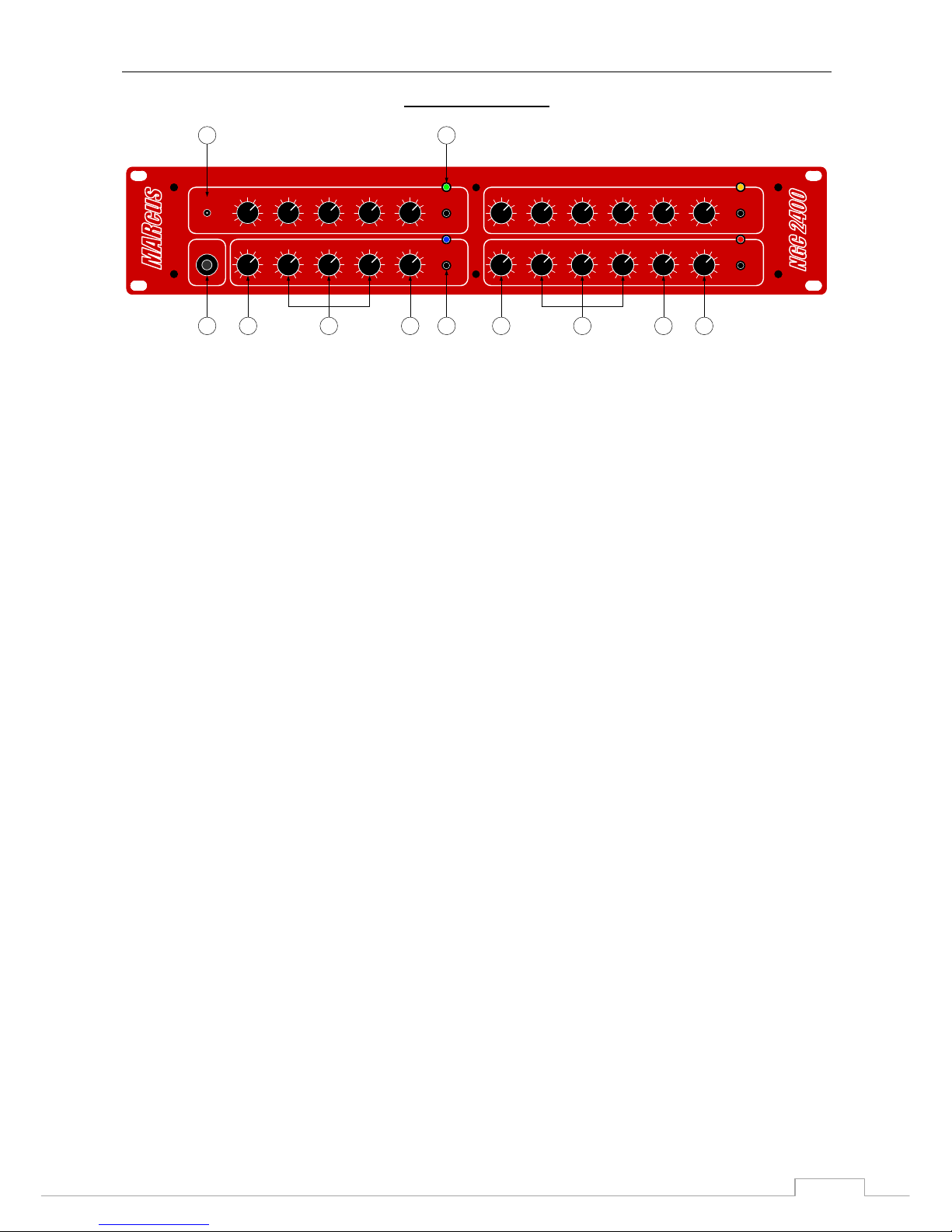
1. Input Jack. This ¼'' jack accepts the output from the guitar.
2. GAIN control of equal Channel I and Channel II control panels. This control
adjusts the amount of drive for Channel I (Channel II). Higher settings of this
control increase additional harmonics and sustain.
3. BASS, MID, and TREBLE controls. These controls represent an
equalization section of Channel I or Channel II.
4. VOLUME control. Adjusts the overal volume of the Channel.
5. CHANNEL SELECT switch. Each Channel section has its own channel
select switch to select one of the four channels as desired.
6. BRIGHT switch. Three-position high-end boost (center = off, left = bright,
right = brighter).
7. Channel ON indicator. Each channel has its own “on” indicator which lights
when the channel is selected. Channel I – green, Channel II – blue, Channel
III – yellow, Channel IV – red.
8. GAIN control of equal Channel III and Channel IV control panels. This
control adjusts the amount of drive for Channel III (Channel IV). Higher
settings of this control increase distortion and sustain.
9. BASS, MID and TREBLE controls. These controls represent an
equalization section of Channel III or Channel IV.
10. PRESENCE and ANGLE controls. These controls add yet another
dimension to powerful equalization groups of controls. Channel IV has
ANGLE control which was intended as custom option. Here it works as
PRESENCE like on Channel III.
11. VOLUME control. Adjusts the overal volume of the Channel.
Page 6
MARcus NGC 2400 User’s Guide
5
REAR PANEL
Footswitch
Record
output
Direct
output
Master
volume
Ground
Lift
1 2 3 4 5 6 7
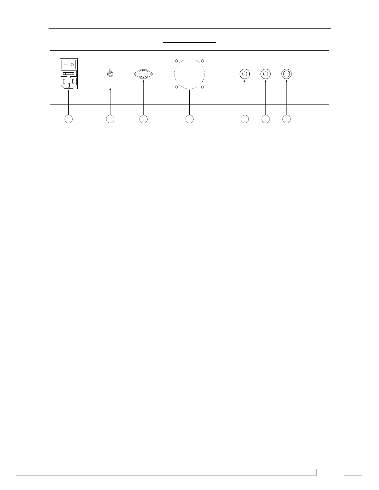
1. POWER INLET module. This Power Inlet module accepts the detachable
power cord included with the unit, and also houses the main power fuse
(500mA).
2. GROUND SWITCH. This switch is used for eliminating ground loops
common to many multi-unit rack systems. Set this switch in the position which
results in the least amount of hum (typically GROUND for stand-alone use
and LIFT for rack installations).
3. FOOTSWITCH jack. This 6-pin DIN connector is dedicated for use with
MARcus 4-channel footswitch.
4. COOLER
5. RECORD OUTPUT. MARcus NGC 2400 has exclusive speaker-simulator
to provide sounding of 4x12 guitar cabinet. This output (stereo ¼'' jack) is
dedicated to give a signal to a line inputs of mixer consoles or to a line input
of computer sound card.
6. DIRECT OUTPUT. ¼'' mono jack is dedicated co connect directly to a
power amp.
7. MASTER VOLUME control. Adjusts the level output from the both DIRECT
and Record OUTPUTS jacks.
Page 7

MARcus NGC 2400 User’s Guide
6
WARNINGS
- Do not block any ventilation openings on the sides or rear of the preamp.
Always give four inches of proper ventilation to the rear of the preamp.
- Do not expose the amplifier to rain, moisture, dripping or splashing water.
Do not place objects filled with liquids on or nearby the amplifier.
- Do not expose the amplifier to direct sunlight or extremely high
temperatures. Always unplug the AC power cord before changing fuses or
tubes. When replacing fuses, use only the same type and rating.
- Be sure to connect to an AC power supply that meets the power supply that
meets the power supply specification, listed on the rear fuse holder.
- If there is any danger of lightning occurring nearby, remove the power plug
from the wall socket in advance.
- Do not use excessive force in handling control buttons, switches and
controls. Do not use solvents to clean the unit, wipe off the exterior with soft
cloth.
 Loading...