

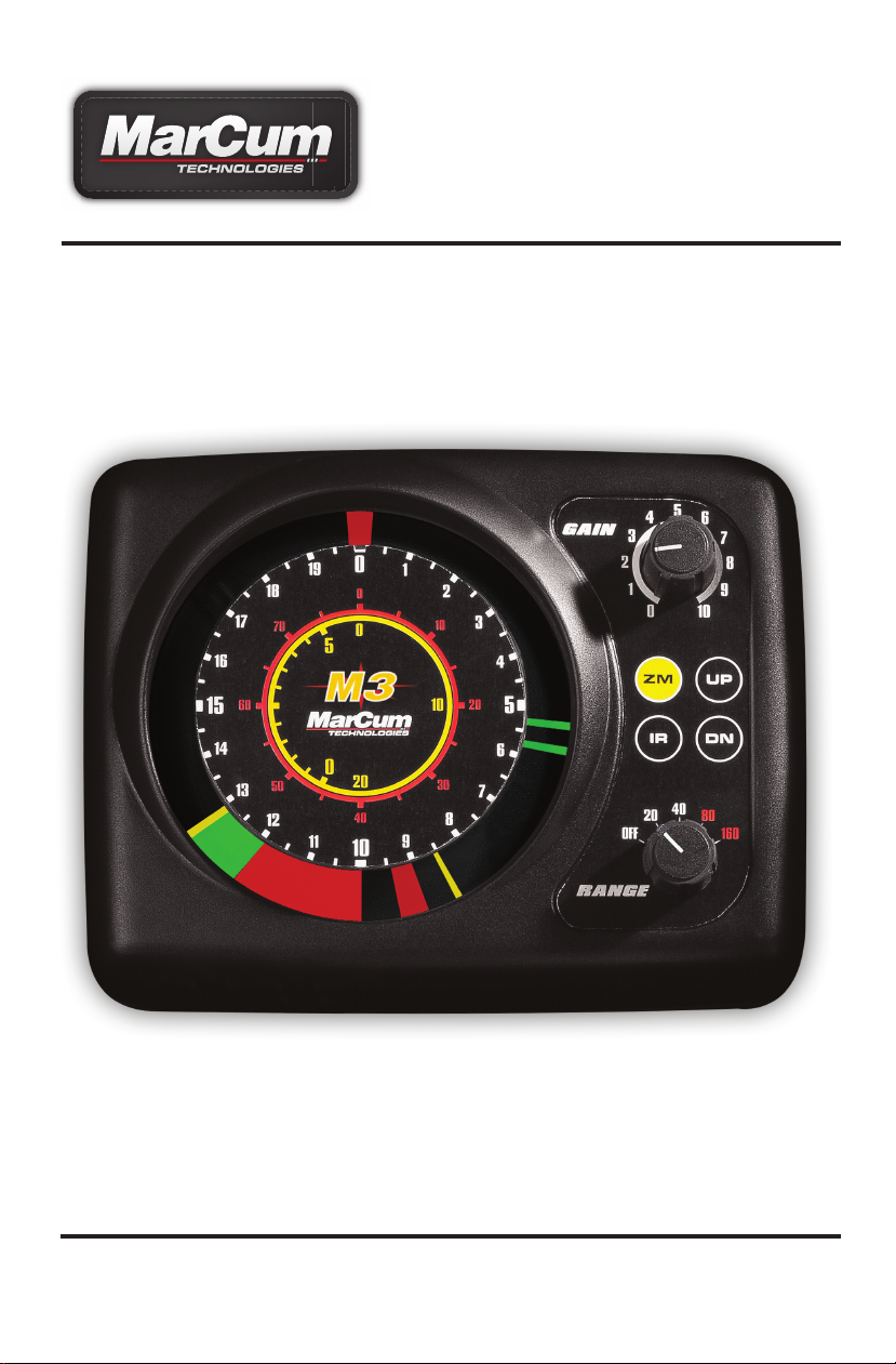
M3
3-Color Ice-Sonar
User Manual
www.MarCumtech.com

www.MarCumtech.com
Introduction
Thank you for purchasing the MarCum M3 True Color sonar unit. The M3 incorporates all of the
sonar technology from the flagship VX series, but now features the new Max Brightness and
Clarity patented MBC lighting. Still featuring 2000 watts of peak-to-peak power, patented
signal interference rejection, auto zoom, and target separation down to 1.5 inches. Our goal is to
set the industry standard for performance while maintaining the highest level of reliability. Please
read this manual carefully before using your M3 system. Only by reading this manual can you
realize the maximum benefit from your purchase — enjoy your new M3 sonar system!
General Description
The M3 True Color sonar unit utilizes three different colors within its display to differentiate
between densities of objects: RED, ORANGE, and GREEN. The use of different colors in defining
return signals is meant to be informative in indicating the size of fish, type of bottom or location of
weeds. The interpretation of these signals improves with experience and use in the field.
The M3 offers multi-level Interference Rejection (IR) from nearby competing units. This is most
prevalent in ice-fishing applications where anglers utilizing sonar are often grouped together within
small areas.
Your MarCum is water and weather resistant and is designed to be used in the outdoors, but in
extreme weather conditions, care should be taken to shield the monitor from driving rain and boat
spray. At no time should the monitor be in direct contact with large amounts of water. Should your
M3 become wet, it is unlikely that any harm will come to it, but make sure to get the entire system
completely dried out as soon as possible.
BATTERY CHARGING
Your MarCum system comes with a 3-stage battery charger. This style of charger has proven to
be the most effective and easiest to use of all charging systems available. Because this is a
3-stage charger, there is no danger of overcharging your battery. When properly cared for, a
sealed lead acid battery will last for at least a couple of years. Batteries are made to be used,
and they need to be used to make the most of them. The most important thing you can do is to
promptly recharge your battery after each use. Not charging your battery immediately after
use is the
number one thing that leads to battery failure.
For safety reasons, it is recommended that you place your system on a flat, hard surface like
cement or tile when charging it, away from any flammable materials. Be sure to disconnect the
charger from the wall when not in use, and avoid leaving your battery hooked up to the charger for
extended periods of time.
When you get home from a trip, put your battery on charge right away and leave it there overnight,
or for around 8-12 hours. Likewise, on the night before an ice fishing trip, put it on the charger
again, just to make sure. Again, there is no danger of overcharging your battery. We often talk to
people who hesitate to charge their battery after each use for fear that the battery will develop a
“memory” and this
TTERY AFTER EVERY USE!!! Be sure to use the charger that came with your system, or a
BA
similar one that is between .5 amp and 1 amp. Using a larger charger, like you would use on a
car, truck, RV, or boat is likely to cause damage to the battery. There is really no danger of
overcharging your battery with a low amp charger, and most chargers automatically go into
“maintenance mode” once a full charge has been achieved.
will lead to a shortened run time—THIS IS FALSE!!! ALWAYS CHARGE YOUR
- 2 -

www.MarCumtech.com
TO CHARGE YOUR BATTERY:
Your battery has a wiring harness attached to it that has “piggyback” terminals on it, enabling you
to keep the power cord from the unit attached to the battery at all times, as well as having the
wiring harness with receptacle for your charger attached at all times. To charge, simply couple the
end of the charger with the end of the wiring harness. It is normal for a green light to appear on the
charger at this time if the charger is plugged into the battery only. It is also normal for the light on
the charger to be green if it is just plugged into the wall. When it is plugged into the wall and
battery, you will see a red LED light appear on the charger. If the light is red, the battery is being
charged. When your battery is fully charged, this red light should change to green. If it is time to
go fishing and the light has not turned green, go fish and try to allow a longer charging period next
time.
Batteries are an expendable item, and must be replaced periodically. The batteries that we use are
the “Sealed Lead Acid” variety, they are 12 volts, and range from 7 to 9 amps. The more amps the
battery has, the longer it will run on a full charge. Your MarCum can be powered off of any battery
that is 12 volts, even a large automotive or deep cycle battery.
If you are having difficulty with the charging process, please see the Troubleshooting on our
website, www.marcumtech.com/support.
If you need to remove the battery, slide the power cord leads from the battery. Remove the strap
that is holding the battery in place and lift the battery out. To replace the battery, place a new
battery of similar specifications into the battery compartment and secure it with the Velcro strap
and re-connect the positive and negative terminals.
Ice System Set-Up
Your M3 comes virtually ready to fish. All you need to do is hook up the positive lead from the M3
power cord to the battery. Your M3 is delivered with a charged battery, so you can take it fishing
right away. Inside the M3 deluxe softcase is an electronics shuttle that has recessed compartments for the battery and the single beam transducer. Take the transducer out of the recessed
holder and rotate the adjustable ice arm out from inside the shuttle. The adjustable ice arm allows
for maximum flexibility in positioning the M3 around the ice hole.
SETTING THE TRANSDUCER FOR ICE FISHING:
When used in conjunction with the retractable pivoting transducer arm and rubber stopper, the
M3’s transducer will automatically level itself in your ice hole. To begin operation, take the
transducer out of the recessed holder, and rotate the adjustable ice arm out from inside the shuttle.
Extend the transducer arm, (the cable should already be threaded through it with stopper in place)
and deploy the transducer into the water. We recommend setting your stopper to have the
transducer down the least amount possible. The MarCum M3 puts out enough power that in most
cases it is not necessary to have your transducer down more than a few inches below the water
line to get a good reading. When the ice thickness is over two feet, it may be necessary to have
your transducer set somewhat farther down. Remember--the less transducer cable you have out,
the easier it is to pull it out of the water when bringing in a fish, or to move to a new location. Under
no circumstances should you ever have the ducer below the ice—this can lead to the ducer
becoming damaged. It is also important that you keep the cable near the center of the ice hole. We
frequently hear from anglers who allowed their cable to freeze into the side of the ice hole. If this
should happen to you, make sure the unit is turned off before attempting to chisel it out. If you
accidentally cut the ducer cable, do not try to use that ducer again.
- 3 -

www.MarCumtech.com
MOVING THE DUCER TO A NEW LOCATION
Being mobile is one of the keys to being successful on the ice. Whenever you move from one spot
to another, it is tempting to leave your transducer hanging on the transducer arm. This is likely to
lead to failure of the transducer arm, and can cause damage to the transducer itself. Always stow
the transducer inside the pack when you are moving. Keeping the amount of transducer cord you
have out at a minimum will make transporting your M3 easier. Similarly, you may need to quickly
remove your transducer from the hole when about to land a fish. We have actually seen anglers
in a panic actually grab the shuttle itself and toss the entire unit to the side. This is no way to treat
any piece of electronics; a much better approach is to simply lift the transducer out of your way by
the cord, and the shuttle itself can be gently pushed aside. Whenever you are moving via sled or
vehicle, always fold up your transducer arm, stow the transducer inside, and close the protective
soft pack.
READING THROUGH ICE
The M3 will provide accurate information reading through ice providing the ice is reasonably clear.
Wet the ice with at least a cup of water to improve the coupling of the transducer to the ice. Place
the face of the transducer firmly on the wetted ice, and you will now be able to see the depth and
fish displayed on your dial. Drilling into the ice 1-2” before taking a reading may be necessary if
the surface of the ice is very rough, or if the ice is filled with air bubbles.
Operation
The M3 utilizes a combination of control knobs (Gain & Range) and keypad (IR) and (ZM) to
change or activate various system functions. The keypad has an audible beep when the key is
depressed to indicate that a system function has been activated. The following is an explanation
of the various system functions.
Range Select - The Range select knob is used for turning the M3 on or off, as well as choosing
the correct depth range. The M3 offers four depth ranges to choose from that can be selected by
rotating the knob clockwise. The depth ranges are 20, 40, 80, or 160 feet. The depth-range setting
is determined by turning the unit on and turning the Gain knob looking for a solid return (band of
light) indicating bottom on the display. If no return is present, then select the 40-, 80-, or 160-foot
range until a bottom reading is displayed on the screen.
Interpreting the different rings of numbers around the dial
When on the 20’ range, simply go by the white numbers. When on the 40’ range, use the outer
white numbers, but multiply x 2 to determine your depth [13 on the dial = 26 feet]. When on the 80’
range, use the red numbers. When on the 160’ range, use the red numbers x 2. The innermost
numbers are for the split screen zoom, and they are used in a similar manner.
Gain Knob - The Gain knob controls the amount of sensitivity required by the unit to pick up
objects like bottom, weeds, fish, smaller bait-fish, or small lures and jigs. The lower the number,
the less sensitivity, conversely higher numbers mean more sensitivity. However, too much Gain
(sensitivity) will result in too much information being displayed, and it becomes difficult to interpret
the return signals. The best Gain setting is achieved by turning up your Gain from 0 until you
receive a clear and steady bottom reading. If you’re looking for your lure or bait, turn up the gain
until you just begin to display your bait without it fading or flickering on the screen. The lower the
sensitivity, the narrower the display segments, the easier it is to distinguish targets. We cannot
emphasize this strongly enough. Too much Gain will only clutter the display with unnecessary
information, making it more difficult to interpret the return signals. Keeping the Gain at minimum
levels will provide you with the most accurate and precise information.
- 4 -

www.MarCumtech.com
Interference Rejection - The Interference Rejection system is designed to knock out competing
return signals from other sonar units being used within proximity. When other sonar units are
causing interference to the display of the M3, activate the IR feature by depressing the IR key
located on the face of the M3. When you press the key, a beep will be heard. There are multiple
levels of interference rejection, and each press of the key will change the level of Interference
Rejection. The correct level of IR will be achieved when the display is clear of display clutter. In
some extreme cases, clutter will be greatly reduced but not eliminated. It is recommended that
only one person in a group adjust the interference rejection at a time.
Zoom - The Zoom function can be activated by depressing the ZM key. An audible beep will
indicate that the Zoom function has been activated. The Zoom function divides the circular display
screen in half. The right half of the display, (12 to 6 o’clock on the dial) will become your entire
surface-to-bottom display. This will be indicated by a RED band of light at the top (zero) and a RED
band of light at the bottom (or 6 o’clock). If you are on the 20-foot depth range, the 12 o’clock
position will be the surface of the water and 6 o’clock will be the bottom of your chosen depth
range (20 feet on the 20-foot scale). When utilizing the Zoom function, you will be reading your
depth markings by viewing the inner circle (YELLOW numeric) located in the center of the M3
display dial. If you select the 40-foot scale, the same applies, except you multiply the YELLOW
numeric markings by 2. The 80-foot range setting is a multiple of 4, and the 160-foot range setting
is a multiple of 8. Once you use the M3 a few times, your brain will automatically make the adjustment without any noticeable thought process. The backside of the display (6 o’clock moving
clockwise to 12 o’clock) is the other half of your split-screen display. This half reads what you see
on the right half, but in a magnified version. This will greatly enhance the precision of your presentation and show that multiple smaller targets might exist on the left half (Zoom) where it appears
that one larger target is showing on the right (normal display). You can determine the size of your
Zoom window (the width or amount of water viewed within the water column) by depressing the
ZM key. If you depress the key once (turning Zoom ON), the window is 5 feet on the 20- or 40-foot
range setting, if you press the ZM key again the Zoom window is expanded to 10 feet. Depress the
ZM key again and the Zoom feature is turned OFF. The 80-foot range allows you a 10-foot viewing
window; depress ZM again and it will become a 20- foot Zoom window. The 160-foot range has a
20-foot window, or it becomes 40-foot when ZM is depressed again
Signal Interpretation
Hard-bottom readings (rock or
strong return signal. Conversely, a soft bottom (mud or silt) will return a weaker signal and will
result in a narrower RED band or possibly even a combined RED and GREEN band. A soft bottom
with weed growth will often appear as a narrow RED or GREEN band combined with both
solid and broken ORANGE segments indicating weeds. Any fish in the weeds may show as
RED or GREEN depending on fish size and relationship within the transmit beam (in the middle
or on the outside of the transmit signal).
Reading Fish – Fish will generally appear as separate targets from the bottom. A fish target can
be displayed as RED, ORANGE or GREEN, depending on the size of the fish and the location
within the transmit beam. Larger fish located in the center of the beam (cone) can appear RED and
will be displayed as a wider band on the display. Smaller fish or fish on the outside of the cone may
appear ORANGE or even GREEN. Fish moving through the transmit beam may change color as
the return signal strengthens or weakens reflecting their location. Fish that are right on the bottom
can appear as part of the bottom. The best indication of a fish sitting right on the bottom is that the
leading edge of the bottom return signal is either ORANGE or possibly a dithering or flickering
RED segment. It is important that the GAIN or sensitivity be kept to a minimum when displaying a
strong bottom return.
gravel) will be displayed by a wide band of RED light indicating a
- 5 -

www.MarCumtech.com
Too much GAIN will flood out the ability to differentiate targets and clutter the display. Fish - Fish
generally appear as separate targets from the bottom. A fish target can be displayed as
will
RED, ORANGE or GREEN, depending on where the fish is located within the cone.
Reading Your Jig – The M3 will pick up and display small objects like jigs, spilt shot, or swivels.
When tuning the unit to display your lure or bait, lower the object to the desired depth and turn up
the GAIN until you see the jig on the display. It is important that the GAIN be set so it displays the
as you raise or lower it. Sound waves emitted by the M3 bounce off targets and return with the
jig
strength of the targets’ density. Denser targets return with a stronger signal, displayed as RED.
Less-dense objects (small fish) return a medium-strength signal, displayed as GREEN. The
least dense objects (weeds, bait-fish, lure) return a weak signal, displayed as ORANGE. Objects
on the edge of the sound cone may appear as ORANGE. A fish moving through the cone may
appear first as ORANGE then GREEN, then RED, depending on where the fish is located within
the cone.
NOTE: Too much GAIN will cause clutter and may make it difficult to distinguish other targets like
fish near the bottom. When tuning the unit to display lures or bait, make sure that the objects are
in the center of the hole and therefore in the center of the transmit beam. If there’s water current
(some lakes have underwater current or movement) and the lure doesn’t weigh much, it may move
to the outer edge of the signal or out of the transmit beam altogether. This will make it difficult or
impossible to pick it up on the display.
Dead Zone - All sonar units will have a dead zone in certain circumstances. This occurs on sharp
drop-offs where the transmit beam (cone) hits the shallower edge of the drop-off and returns
before the deeper edge returns. This in effect creates an undisplayed area between the shallower
and deeper water within the transmit beam.
Product Performance Specifications
Output Power
Depth Ranges
Transmit Frequency
Current Draw
Operating Voltage
Display Colors
Transducer Cone Angle
Target Separation
2000 watts peak to peak
20, 40, 80, & 160 feet
200 KHz
300 mA
10.5 to 15 volts (12-volt DC)
Red, Orange, Green
20 degrees (all transducers)
1.5 inches (20-foot depth scale) 1 inch
in Zoom Mode (20-foot depth scale)
WARRANTY - SONAR
MarCum warranties this product to be free from defects in materials and workmanship for two
years from the date of purchase. This warranty applies to customers who properly complete
the online product registration
www.marcumtech.com/support.
MarCum Technologies will repair or replace any components that fail in normal use. Failures due
to abuse, misuse, unauthorized alteration, modification, or repair are not covered. The warranty is
valid only for the original owner who purchases the unit from an authorized dealer. An original
sales receipt dated within the warranty period is required for all warranty claims.
In an effort to best serve our customers, MarCum Technologies has set a standardized battery
warranty policy.
website, www.MarCumtech.com/support, for full details on warranty coverage.
Battery warranty coverage requires a proof of purchase. Please see our
form found on the MarCum Technologies Website:
- 6 -

www.MarCumtech.com
HOW TO OBTAIN SERVICE
If your system is malfunctioning, check the troubleshooting section of our website. You may
find that the solution to your problem is something you can resolve yourself. If you need to
send it in, there is no need to contact our office. Getting repairs made is as simple as
going to our website, www.MarCumtech.com clicking the support tab and then filling out
the MarCum Warranty Claim.
If your system is under warranty, be sure to attach a picture/scan of your proof of purchase
with date included. If your system is out of warranty, we have a flat rate fee that will cover the
cost of repairs, including parts and labor. You will find the non-warranty claim on our support
site.
Once you have completed and submitted a claim form, package the unit as described on the
website and ship it to us.
Some people are more comfortable calling for shipping instructions. During peak ice season, we
sometimes receive a high volume of calls, making it impossible to get to all customers who
phone in. For this reason, strongly consider using the on-line forms at www.marcumtech.com/
support or the "Live Chat" option.
OUR ADDRESS:
MARCUM TECHNOLOGIES
ATTN: SERVICE DEPT.
3943 QUEBEC AVE NORTH
MINNEAPOLIS, MN 55427
Please send your email inquiries to service@marcumtech.com
If you are unable to use email or internet, you may call us at 763-512-3987.
The customer is responsible for shipping costs associated with returning the system to
MarCum Technologies. MarCum will pay for shipping the repaired system back to the customer
it is still under warranty. All out of warranty services will be charged a fee for service and
while
shipping which must be paid in advance. The unit should be securely packed and shipped “prepaid freight” and insured to MarCum Technologies. It is the customer’s full responsibility to track
their products sent out in the mail or other forms of delivery service. MarCum Technologies
will not be liable for packages lost en route to us. Unless specified otherwise, do not include
batteries or other acces-sories when returning the product for repair. MarCum Technologies will
not be responsible for lost or damaged accessories. Turnaround time can vary, on average it is
about 1 week.
Our office hours are Monday – Friday, 8 – 4 Central Time.
International callers may use 888-778-1208.
- 7 -

www.MarCumtech.com
www.MarCumtech.com
MarCum Technologies
3943 Quebec Ave N
Minneapolis, MN 55427
MarCum User Manuals are available for downloads from
www.MarCumtech.com
2019-0313
 Loading...