

Mar Cor Purification WRO 300, WRO 300 H Service Manual
Mar Cor Purification
WRO 300/300 H
Service Manual

Important User Information
Copyright © 2012 by Mar Cor Purification, Inc.
All rights reserved. No part of the contents of this manual may
be reproduced, copied, or transmitted in any form or by any
means including graphic, electronic, or mechanical methods or
photocopying, recording, or information storage and retrieval
systems without the written permission of the publisher, unless
it is for the purchaser's personal use.
The information in this manual is subject to change without
notice and does not represent a commitment on the part of Mar
Cor Purification (MCP). MCP does not assume any responsibility for any errors that may appear in this manual. In no event
will MCP be liable for technical or editorial omissions made
herein, nor for direct, indirect, special, incidental, or consequential damages resulting from the use or defect of this manual.
The information in this document is not intended to cover all
possible conditions and situations that might occur. The end
user must exercise caution and common sense when installing, using, or maintaining MCP products. If any questions or
problems arise, call MCP Technical Services at 1-800-633-
3080.
Intended Use
MCP products are intended to be installed and used as
described in this manual and other related MCP literature.

WRO 300/300 H
Table of Contents
Table of Contents
Important User Information. . . . . . . . . . . . . . . . . . . . . . . 2
Intended Use. . . . . . . . . . . . . . . . . . . . . . . . . . . . . . . . . . 2
Table of Contents. . . . . . . . . . . . . . . . . . . . . . . . . . . . . . . . 3
Preface . . . . . . . . . . . . . . . . . . . . . . . . . . . . . . . . . . . . . . . . 7
Related Manuals. . . . . . . . . . . . . . . . . . . . . . . . . . . . . . . 7
Safety Message Definitions . . . . . . . . . . . . . . . . . . . . . . 7
Safety Considerations. . . . . . . . . . . . . . . . . . . . . . . . . . . 7
List of Symbols . . . . . . . . . . . . . . . . . . . . . . . . . . . . . . . . 9
Certification Marks . . . . . . . . . . . . . . . . . . . . . . . . . . . . 10
IPR - Intellectual Property Rights . . . . . . . . . . . . . . . . . 10
Copyright. . . . . . . . . . . . . . . . . . . . . . . . . . . . . . . . . 10
Trademarks . . . . . . . . . . . . . . . . . . . . . . . . . . . . . . . 10
Manufacturer . . . . . . . . . . . . . . . . . . . . . . . . . . . . . . 10
Introduction . . . . . . . . . . . . . . . . . . . . . . . . . . . . . . . . . . . 11
Intended Use. . . . . . . . . . . . . . . . . . . . . . . . . . . . . . . . . 11
Reverse Osmosis . . . . . . . . . . . . . . . . . . . . . . . . . . . . . 11
General Function . . . . . . . . . . . . . . . . . . . . . . . . . . . . . 11
Water Quality . . . . . . . . . . . . . . . . . . . . . . . . . . . . . . . . 12
Pretreatment . . . . . . . . . . . . . . . . . . . . . . . . . . . . . . 12
Microbiology . . . . . . . . . . . . . . . . . . . . . . . . . . . . . . 12
Check Water Quality . . . . . . . . . . . . . . . . . . . . . . . . 12
Technical Description . . . . . . . . . . . . . . . . . . . . . . . . . . . 15
Flow Diagrams . . . . . . . . . . . . . . . . . . . . . . . . . . . . . . . 15
Components in Flow Diagram. . . . . . . . . . . . . . . . . . . . 16
Flow Description . . . . . . . . . . . . . . . . . . . . . . . . . . . . . . 17
Run . . . . . . . . . . . . . . . . . . . . . . . . . . . . . . . . . . . . . 17
Chemical Disinfection and Cleaning . . . . . . . . . . . . 19
Components . . . . . . . . . . . . . . . . . . . . . . . . . . . . . . . . . 20
Overview . . . . . . . . . . . . . . . . . . . . . . . . . . . . . . . . . 20
Casing . . . . . . . . . . . . . . . . . . . . . . . . . . . . . . . . . . . 21
Operator Panel . . . . . . . . . . . . . . . . . . . . . . . . . . . . 22
Power Supply Unit. . . . . . . . . . . . . . . . . . . . . . . . . . 22
Fan . . . . . . . . . . . . . . . . . . . . . . . . . . . . . . . . . . . . . 22
Y Coupling and Product Water Loop. . . . . . . . . . . . 23
Tank. . . . . . . . . . . . . . . . . . . . . . . . . . . . . . . . . . . . . 23
RO Modules. . . . . . . . . . . . . . . . . . . . . . . . . . . . . . . 24
Motor and RO Pump Unit . . . . . . . . . . . . . . . . . . . . 25
Cooling Fan. . . . . . . . . . . . . . . . . . . . . . . . . . . . . . . 25
Flow Block Complete. . . . . . . . . . . . . . . . . . . . . . . . 26
Needle Valve. . . . . . . . . . . . . . . . . . . . . . . . . . . . . . 27
Chemical Intake Unit . . . . . . . . . . . . . . . . . . . . . . . . 27
P/N 3027437 Rev. B
3

Table of Contents
WRO 300/300 H
CPU Board . . . . . . . . . . . . . . . . . . . . . . . . . . . . . . . 28
AC Relay Board (only WRO 300 H) . . . . . . . . . . . . 28
External Communication Connections . . . . . . . . . . 28
Heaters (only WRO 300 H) . . . . . . . . . . . . . . . . . . . 28
Mains Power Cable . . . . . . . . . . . . . . . . . . . . . . . . . 29
Description of Indications . . . . . . . . . . . . . . . . . . . . . . . 29
Light Indications. . . . . . . . . . . . . . . . . . . . . . . . . . . . 29
Buzzer Sounds . . . . . . . . . . . . . . . . . . . . . . . . . . . . 31
Operation Functions . . . . . . . . . . . . . . . . . . . . . . . . . . . 31
Standby Mode . . . . . . . . . . . . . . . . . . . . . . . . . . . . . 31
Auto Flush . . . . . . . . . . . . . . . . . . . . . . . . . . . . . . . . 31
Run Mode . . . . . . . . . . . . . . . . . . . . . . . . . . . . . . . . 32
Changing from Run to Standby Mode. . . . . . . . . . . . . . 35
Start After Power Loss. . . . . . . . . . . . . . . . . . . . . . . 35
Hygiene Functions . . . . . . . . . . . . . . . . . . . . . . . . . . . . 37
Manual Flush. . . . . . . . . . . . . . . . . . . . . . . . . . . . . . 37
Chemical Disinfection and Cleaning . . . . . . . . . . . . 37
Dwell and Rinse. . . . . . . . . . . . . . . . . . . . . . . . . . . . 44
Preservation . . . . . . . . . . . . . . . . . . . . . . . . . . . . . . 46
Heat Disinfection (only WRO 300 H). . . . . . . . . . . . 48
Features — Extra Functions. . . . . . . . . . . . . . . . . . . . . 53
Water Save Function. . . . . . . . . . . . . . . . . . . . . . . . 53
Reminders. . . . . . . . . . . . . . . . . . . . . . . . . . . . . . . . 54
Time Channels . . . . . . . . . . . . . . . . . . . . . . . . . . . . 55
Replacements. . . . . . . . . . . . . . . . . . . . . . . . . . . . . . . . . . 57
Replacement Matrix . . . . . . . . . . . . . . . . . . . . . . . . . . . 57
Internal Service. . . . . . . . . . . . . . . . . . . . . . . . . . . . . . . . . 59
Changing Configuration Parameters. . . . . . . . . . . . . . . 59
Internal Service Mode. . . . . . . . . . . . . . . . . . . . . . . . . . 59
Enter Internal Service Mode . . . . . . . . . . . . . . . . . . 59
Internal Service Loop. . . . . . . . . . . . . . . . . . . . . . . . 60
PC Support Software . . . . . . . . . . . . . . . . . . . . . . . . . . 71
USB Serial Driver Installation . . . . . . . . . . . . . . . . . 71
GXL — Logging. . . . . . . . . . . . . . . . . . . . . . . . . . . . 74
GXP — Preset. . . . . . . . . . . . . . . . . . . . . . . . . . . . . 74
Checksum Status . . . . . . . . . . . . . . . . . . . . . . . . . . 75
GWD - Download. . . . . . . . . . . . . . . . . . . . . . . . . . . 75
Start the GWD. . . . . . . . . . . . . . . . . . . . . . . . . . . . . 75
Presets and Defaults. . . . . . . . . . . . . . . . . . . . . . . . . . . 79
Change Presets for WRO 300 H. . . . . . . . . . . . . . . 82
RO Pump. . . . . . . . . . . . . . . . . . . . . . . . . . . . . . . . . 83
Tank Control . . . . . . . . . . . . . . . . . . . . . . . . . . . . . . 83
Water Save . . . . . . . . . . . . . . . . . . . . . . . . . . . . . . . 84
Conductivity. . . . . . . . . . . . . . . . . . . . . . . . . . . . . . . 85
User Interface Panel (LCD). . . . . . . . . . . . . . . . . . . 87
4
P/N 3027437 Rev. B

WRO 300/300 H
Table of Contents
Heat. . . . . . . . . . . . . . . . . . . . . . . . . . . . . . . . . . . . . 87
Disinfection Protocol Manager. . . . . . . . . . . . . . . . . 90
Chemical Disinfection . . . . . . . . . . . . . . . . . . . . . . . 95
Time Manager . . . . . . . . . . . . . . . . . . . . . . . . . . . . . 97
Time Channels . . . . . . . . . . . . . . . . . . . . . . . . . . . . 98
Reminders. . . . . . . . . . . . . . . . . . . . . . . . . . . . . . . . 99
Remote . . . . . . . . . . . . . . . . . . . . . . . . . . . . . . . . . 100
External relay. . . . . . . . . . . . . . . . . . . . . . . . . . . . . 101
Wiring Diagram. . . . . . . . . . . . . . . . . . . . . . . . . . . . . . . . 103
WRO 300 H. . . . . . . . . . . . . . . . . . . . . . . . . . . . . . . . . 103
WRO 300 . . . . . . . . . . . . . . . . . . . . . . . . . . . . . . . . . . 104
Maintenance . . . . . . . . . . . . . . . . . . . . . . . . . . . . . . . . . . 105
Water Testing . . . . . . . . . . . . . . . . . . . . . . . . . . . . . . . 105
Total Chlorine . . . . . . . . . . . . . . . . . . . . . . . . . . . . 105
Residual Hardness . . . . . . . . . . . . . . . . . . . . . . . . 105
Performance Tests . . . . . . . . . . . . . . . . . . . . . . . . 105
Changing Prefilter Cartridges . . . . . . . . . . . . . . . . . . . 105
General . . . . . . . . . . . . . . . . . . . . . . . . . . . . . . . . . 105
Replacing Carbon Block Filters. . . . . . . . . . . . . . . 106
Power Supply Unit . . . . . . . . . . . . . . . . . . . . . . . . . . . 106
Air Filter. . . . . . . . . . . . . . . . . . . . . . . . . . . . . . . . . 106
Protective Earth (PE). . . . . . . . . . . . . . . . . . . . . . . 106
Adjusting Product Water Flow. . . . . . . . . . . . . . . . . . . 106
Using Adjustment Tool 3027493 . . . . . . . . . . . . . . 106
Using Adjustment Tool WT100TEST. . . . . . . . . . . 108
Conductivity Adjustment . . . . . . . . . . . . . . . . . . . . . . . 109
Adjustment Procedure. . . . . . . . . . . . . . . . . . . . . . 109
Checking Operator Panel . . . . . . . . . . . . . . . . . . . . . . 110
Checking Chemical Intake O-rings . . . . . . . . . . . . . . . 111
Battery Replacement . . . . . . . . . . . . . . . . . . . . . . . . . 111
WRO 300/300 H Battery . . . . . . . . . . . . . . . . . . . . 111
Battery and Electronic Waste Handling. . . . . . . . . 111
Waste Handling. . . . . . . . . . . . . . . . . . . . . . . . . . . 112
P/N 3027437 Rev. B
Electrical Safety . . . . . . . . . . . . . . . . . . . . . . . . . . . . . . . 113
Protective Earth Test . . . . . . . . . . . . . . . . . . . . . . . . . 113
Test Equipment for PET Test.. . . . . . . . . . . . . . . . 113
PET for WRO 300 . . . . . . . . . . . . . . . . . . . . . . . . . 113
PET for WRO 300 H . . . . . . . . . . . . . . . . . . . . . . . 113
Electrical Leakage Test (ELT). . . . . . . . . . . . . . . . . . . 113
ELT Test Equipment . . . . . . . . . . . . . . . . . . . . . . . 113
ELT General Conditions . . . . . . . . . . . . . . . . . . . . 113
ELT WRO 300. . . . . . . . . . . . . . . . . . . . . . . . . . . . 114
ELT WRO 300 H . . . . . . . . . . . . . . . . . . . . . . . . . . 114
Earth Current Limits. . . . . . . . . . . . . . . . . . . . . . . . 114
5

Table of Contents
Technical Data . . . . . . . . . . . . . . . . . . . . . . . . . . . . . . . . 115
Troubleshooting. . . . . . . . . . . . . . . . . . . . . . . . . . . . . . . 125
WRO 300/300 H
Performance and Specification. . . . . . . . . . . . . . . . . . 115
Chemical Disinfection . . . . . . . . . . . . . . . . . . . . . . . . . 119
Physical Data . . . . . . . . . . . . . . . . . . . . . . . . . . . . . . . 119
Materials Contacting Product Water. . . . . . . . . . . . . . 120
Environmental Data . . . . . . . . . . . . . . . . . . . . . . . . . . 120
Electromagnetic Environment. . . . . . . . . . . . . . . . . . . 121
Safety . . . . . . . . . . . . . . . . . . . . . . . . . . . . . . . . . . . . . 124
Alarms. . . . . . . . . . . . . . . . . . . . . . . . . . . . . . . . . . . . . 125
General . . . . . . . . . . . . . . . . . . . . . . . . . . . . . . . . . 125
Internal Error (103:N). . . . . . . . . . . . . . . . . . . . . . . 127
Internal Error (104) . . . . . . . . . . . . . . . . . . . . . . . . 131
Operation. . . . . . . . . . . . . . . . . . . . . . . . . . . . . . . . 132
Heat (only WRO 300 H). . . . . . . . . . . . . . . . . . . . . 138
Chem/Rinse. . . . . . . . . . . . . . . . . . . . . . . . . . . . . . 139
Boot Loader . . . . . . . . . . . . . . . . . . . . . . . . . . . . . . . . 141
Index . . . . . . . . . . . . . . . . . . . . . . . . . . . . . . . . . . . . . . . . 143
6
P/N 3027437 Rev. B

WRO 300/300 H
Preface
Related Manuals
This manual provides the information needed to carry out maintenance
and to identify and remedy any fault that may occur on the WRO 300
water purification unit and the WRO 300 H water purification unit.
The complete model name WRO 300 unit or WRO 300 H unit is used
only when the information is specific and only valid for one of the models. The WRO unit refers to information valid for both models.
The list below shows manuals related to this Service Manual. Always
specify the revision level when ordering the manual for your water purification machine.
Installation Guide, WRO 300/300 H 3027502
Operator’s Manual WRO 300 3027435
Operator’s Manual WRO 300
H
3027436
Preface
Safety Message Definitions
WARNING
Is used to alert the user/operator not to take a certain action,
which if taken can cause a potential hazard and result in a
serious adverse reaction, injury or death. A warning may also
be used to alert the user/operator to take a certain action to
avoid the potential hazard as above.
CAUTION
Is used to alert the user/operator to take a certain action to
protect against a potential hazard which, if ignored, could have
an adverse effect on the patient or the device. A caution may
also be used to alert the user/operator not to take a certain
action to avoid the potential hazard as above.
NOTE
A reminder to the user/operator on normal treatment activity and on
what is a suitable action in a particular situation.
Safety Considerations
WARNING
Unauthorized installation, modifications, alterations or repair of
the WRO unit may result in malfunctioning or have other serious
consequences for the safe operation of the equipment.
P/N 3027437 Rev. B
7

Preface
WRO 300/300 H
CAUTION
• Dialysis machines that are supplied with water from the WRO
unit, must comply with IEC 60601-2-16.
• The WRO unit should only be operated by persons trained in
the use of this equipment and who have studied the instructions in the Operator’s Manual. If the WRO unit does not perform as described in the Operator’s Manual, it should not be
used until the condition is rectified.
• The operator should pay attention to alarms and follow the
instructions, warnings, cautions and notes given in the manual.
• The use of mobile telephones or communication equipment
in the vicinity of the WRO unit could adversely influence the
performance of the machine.
• The WRO unit needs special precautions regarding EMC and
needs to be installed and put into service according to the
EMC information provided in the Operator’s and Service
Manual (refer to Technical Data on page 115).
• The WRO unit is not suitable for use in the presence of a flammable anesthetic mixture with air or with oxygen or nitrous
oxide.
• The WRO unit will perform as designed only if it is used and
maintained in accordance with MCP’s instructions. Any warranties made by MCP with respect to the WRO unit, are void
if the equipment is not used in accordance with the instructions provided. MCP will not accept responsibility for any
damage or injury resulting from improper use or maintenance
or unauthorized repair.
• The user must verify the quality of the protective earth in the
installation.
• U.S. Federal law restricts this device to sale by, or on the
order of, a physician.
NOTE
• On delivery the WRO unit is filled with preservation and antifreeze solution. This solution must be rinsed out before the WRO
unit is put into operation.
• During transportation and storage the equipment must be kept in
its original packing. If transportation or storage time is more than
15 weeks the environmental data relating to the operation must
be fulfilled (refer to Technical Data on page 115).
• The WRO unit is intended for continuous operation.
8
P/N 3027437 Rev. B
WRO 300/300 H
CB
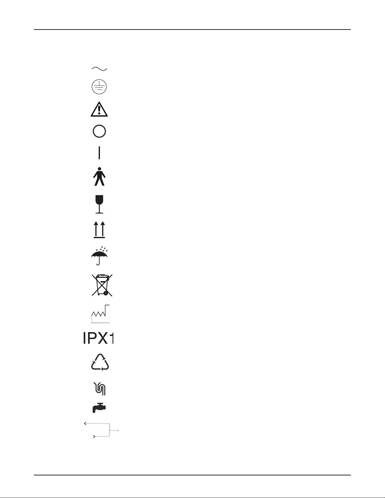
List of Symbols
Preface
Alternating current
Protective earth (ground)
Warning, consult accompanying documents
Off (power, disconnection from the mains)
On (power, connection to the mains)
Type B, applied part
Handle with care
This way up
Keep dry
Separate collection for electrical and electronic
equipment
Year of manufacturing
The WRO 300/300 H is protected against dripping
water
Recycling symbol -General
Reject water connection
Feed water inlet connection
P/N 3027437 Rev. B
Loop connections (Product water outlet and return)
9

Preface
WRO 300/300 H
ME equipment and ME systems that include RF
transmitters or that intentionally apply RF electromagnetic energy for diagnosis or treatment shall be
labeled with this symbol.
Certification Marks
The CSA(C-US) mark indicates that the WRO 300/
300 H water purification units conform to the requirements related to safety of medical devices for the US
and Canada. The C and the US adjacent to the CSA
mark indicates that the WRO 300/300 H water purification units have been evaluated to the applicable
ANSI/UL and CSA standards for use in the US and
Canada.
IPR - Intellectual Property Rights
Copyright
© 2012 Mar Cor Purification, Inc.
Trademarks
DIALOX® is a trademark registered in several countries, including Sweden, United
Kingdom and Japan by their respective owners.
MINNCARE® is a trademark of Minntech registered in several countries including
United States and United Kingdom.
MINNCLEAN® is a trademark of Minntech registered in several countries including
the United States.
SteriChek® is a trademark registered in several countries including the United
States and Japan by their respective owners.
ULTRASIL® is a trademark of Ecolab registered in several countries including Australia and Canada.
Manufacturer
Mar Cor Purification, Inc.
14550 28th Avenue North
Plymouth, MN 55447
USA
Phone: 1-800-633-3080
Fax (Customer Service): 1-763-210-3868
www.mcpur.com
10
P/N 3027437 Rev. B
WRO 300/300 H
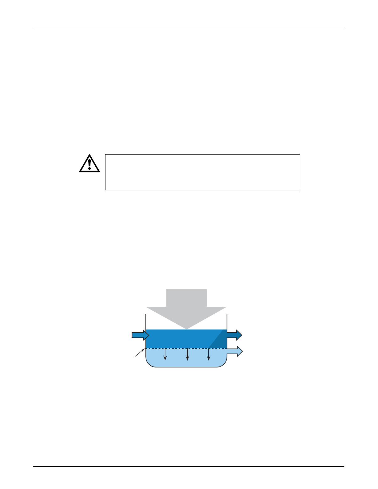
product water
Pressure
membrane
feed water
reject water
1 Introduction
1.1 Intended Use
Introduction
The MCP WRO 300/300 H Water Purification Unit is intended to be
used as a dialysis accessory to produce water through reverse osmosis for one hemodialysis equipment.
The WRO 300/300 H can be connected to hemodialysis equipment
used both in hospitals and in home environments, in conjunction with
appropriate pre and post treatment units, as a part of a water treatment
system designed to meet applicable regulations or standards for water
for dialysis, for example current AAMI and Federal (U.S.) standards.
CAUTION
The water produced by the WRO unit should be analyzed at
installation and on a regular basis to verify that it conforms to
applicable regulations or standards for water for dialysis.
1.2 Reverse Osmosis
Reverse osmosis (RO) is a membrane process that is the most widely
used technique for purification of water for dialysis. When the feed
water is in contact with the semipermeable membrane (the most vital
part of the system) and a high pressure is applied, water will flow
through the membrane to the product water side. Most of the other
constituents (dissolved salts, particles, bacteria and pyrogens) will
remain on the feed water side of the membrane and be flushed to drain
as reject water.
Fig.1.1 — Principal of reverse osmosis
P/N 3027437 Rev. B
1.3 General Function
A high-pressure pump feeds water (usually pretreated water) into the
RO module, containing the membrane. The product water leaves the
RO module through the product water outlet into the product water
loop, to which the dialysis machine is connected. The reject water
leaves the WRO unit via the drain outlet.
11
Introduction
WRO 300/300 H
1.4 Water Quality
1.4.1 Pretreatment
The quality of the incoming water varies from one place to another. Different pretreatment equipment may be required depending on the local
water quality and regulations. An acceptable quality of the feed water
is required, that is in accordance to Technical Data on page 115. As a
minimum, 5 micron prefiltration must be applied. Additional pretreatment, such as carbon filters and softener, may be required depending
on the feed water quality.
WARNING
This device does not remove chlorine and chloramines from the
water. Carbon filtration to remove these substances is therefore
required if the total chlorine concentration might exceed 0.1 mg/l
(ppm). Severe patient injury may otherwise occur. Ensure by testing or by other means that the total chlorine concentration is
below 0.1 mg/l (ppm) prior to initiating dialysis treatment.
1.4.2 Microbiology
The water quality is a very important factor in achieving and maintaining an adequate quality of the dialysis fluid. The microbiological quality
of the product water depends not only on technical parameters such as
retention rates of membranes, but also to a large extent on other factors:
• Feed water shall comply to relevant standards for drinking water.
• Handle taps and connectors in such a manner to avoid microbiological contamination (any pretreatment device, the WRO unit and
the dialysis machine).
• Provide for regular and pro-active disinfection of the WRO unit.
• Set up air gap between the drain outlet and the drain to avoid
microbiological contamination from the drainage system. Refer to
the Installation Guide for the WRO unit.
1.4.3 Check Water Quality
The ions in the water effect the conductivity; the ability to conduct an
electric current. To get an indication of the water quality from a chemical perspective, the WRO unit measures the conductivity of the feed
water and the product water. The conductivity values (µS/cm) indicate
the performance of the WRO unit. Further water tests are, however,
necessary. Refer to Water Testing on page 105.
12
P/N 3027437 Rev. B

WRO 300/300 H
Introduction
CAUTION
The conductivity value does not always indicate the suitability of
the water for dialysis. For example, aluminium may be present in
concentrations well exceeding recommended standards without
affecting the conductivity. Therefore the quality of the product
water, used for dialysis, should be verified by regular analysis of
the water.
P/N 3027437 Rev. B
13

Introduction
WRO 300/300 H
This page is blank.
14
P/N 3027437 Rev. B
WRO 300/300 H
C2T1
RO module
Tank
Needle
valve
Constant flow valve
Feed
water
Chemical
Connector
Drain
Tank air vent
INVA
Chemical
intake
pump
RO pump
L.H.
L.L.
L.E.
Chemical
Intake
OFVA
BYVA
REVA
Drain
Drain
outlet
Product
water
Loop
Constant
flow valve
Spray nozzle
FT2
Heater A
Heater B
Flow meter
T3
C1
Flow block
12 3
4
5
8
6
9
10
7
11
12 13 14
16
15
17
18
19
20
21
22
23
25
24
26
28
27
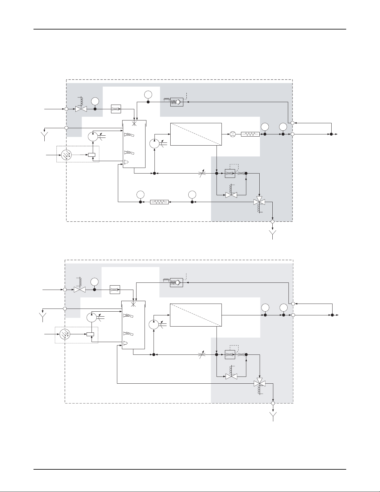
Fig.2.1 — Flow diagram for the WRO 300 H unit
C2T1
RO module
Tank
Needle
valve
Constant flow valve
Feed
water
Chemical
Connector
Drain
Tank air vent
INVA
RO pump
L.H.
L.L.
L.E.
Chemical
Intake
OFVA
BYVA
REVA
Drain
Drain
outlet
Product
water
Loop
Constant
flow valve
Spray nozzle
C1
Flow block
12 3
4
5
8
6
9
7
12 13 14
15
17
18
19
20
25
24
26
28
27
Chemical
intake
pump
Fig.2.2 — Flow diagram for the WRO 300 unit
2 Technical Description
2.1 Flow Diagrams
Technical Description
P/N 3027437 Rev. B
Components in the grey area in the illustrations above are mounted on
the flow block.
15

Technical Description
2.2 Components in Flow Diagram
Components Additional Information
1 Inlet valve (INVA) Two-way solenoid valve
2 Conductivity cell (C1) Monitor feed water conductivity
3 Constant flow valve
4 Tank Providing air gap
5 High level sensor (LH) Float level switch
6 Low level sensor (LL) Float level switch
7 Empty level sensor (LE) Optical sensor
8RO pump
9 RO module The WRO 300 unit and the WRO 300
10 Flow meter In product water line
11 Heater B In product water line only in the
12 Temperature sensor (T1) For product water
13 Conductivity cell (C2) Monitor product water conductivity
14 Product water loop To and from the dialysis machine
15 Overflow valve (OFVA) Two-way solenoid valve
16 Temperature sensor (T3)
product water return
17 Needle valve For reject recirculation
18 Constant flow valve 1200 ml / minute when BYVA (19) is
19 Reject bypass valve (BYVA) The two-way solenoid valve,
20 Reject valve (REVA) Three-way solenoid valve
21 Flow indicator Recirculated reject water only in the
22 Heater A Recirculated reject water
23 Temperature sensor (T2) Recirculated reject water
24 Chemical intake
25 Three-way valve Manual operation
26 Optical sensor Detects the wand
27 Chemical intake pump
Approximately
H unit have different membranes and
different pressure vessels.
(Can also be installed in the WRO 300
unit, refer to separate Spare Part
Instruction).
for product water return
closed.
when active (open), most of the reject
water bypasses the constant flow
valve (18) and the pressure in the
WRO unit is minimized.
diverts reject water either to tank or to
drain.
4000 ml / minute
WRO 300/300 H
only in the
WRO 300 H unit
WRO 300 H unit
only in the
WRO 300 H unit
WRO 300 H unit
16
P/N 3027437 Rev. B
WRO 300/300 H
C2T1
RO module
Tank
Needle
valve
Constant flow valve
Feed
water
Chemical
Connector
Drain
Tank air vent
INVA
Chemical
intake
pump
RO pump
L.H.
L.L.
L.E.
Chemical
Intake
OFVA
BYVA
REVA
Drain
Drain
outlet
Product
water
Loop
Constant
flow valve
Spray nozzle
FT2
Heater A
Heater B
Flow meter
T3
C1
Flow block
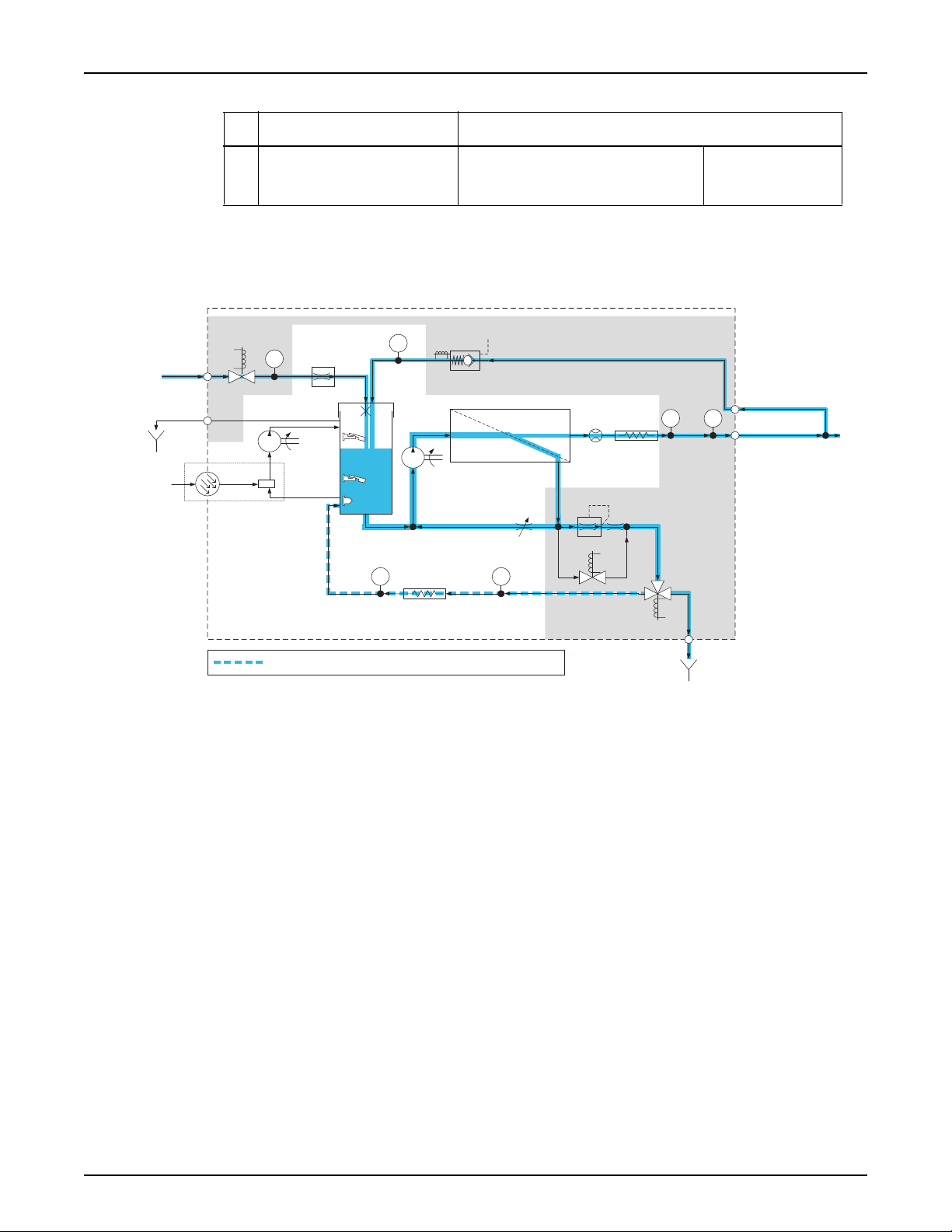
= only during Water Save phases if the function is enabled
2.3 Flow Description
2.3.1 Run
Technical Description
Components Additional Information
28 Tank air vent Connects the tank to the atmosphere
and is also used as overflow connection.
Fig.2.3 — Flow description
The feed water enters the WRO unit through the inlet solenoid valve
INVA. The conductivity cell C1 monitors the feed water conductivity.
The feed water passes the constant flow valve which regulates a
steady flow of water into the tank, approximately 4 l/min, if the feed
water pressure is above minimum pressure.
The low and high level sensors in the tank (LL and LH) detect the
water level and the program controls the opening and closing of the
inlet solenoid valve INVA. INVA is open during filling, and closes when
the water level reaches LH. INVA opens again when the water level is
below LL. If the water level in the tank gets too high, excess water is
drained through the tank air vent (overflow connection). The RO pump
stops when the empty level sensor LE detects air.
The RO-pump creates the feed water flow required for the reverse
osmosis process. The pump speed ramps up during the initial two to
three seconds. Higher pressure forces more water through the membrane. (The manually adjusted needle valve effects the water pressure
in the RO module.).
P/N 3027437 Rev. B
17

Technical Description
NOTE
High flow velocity over the RO membrane is important for proper
function of the WRO unit. Part of the reject water is recirculated
through the needle valve, while still maintaining low water consumption. Also, excess product water is recirculated to save water.
When the product water leaves the RO module in a WRO 300 H unit, it
flows by the flow meter, the heater B, and the temperature sensor T1,
(in a WRO 300 unit only T1). The conductivity cell C2 monitors the
product water conductivity.
The product water leaves the WRO unit through the product water outlet and flows to the dialysis machine through the product water loop.
Excess product water, not used by the dialysis machine, returns to the
tank through the overflow solenoid valve OFVA (for functionality of the
OFVA, refer to page 26). In a WRO 300 H unit, the water flows across
the temperature sensor T3 before entering the tank.
The reject water leaves the RO module and flows through the constant
flow valve which regulates a steady flow of reject water to the threeway solenoid valve REVA. The rest of the reject water goes back to the
RO pump through the needle valve.
WRO 300/300 H
NOTE
As the needle valve is closed, it creates higher pressure in the RO
module and lower recirculation flow. Do not close the valve more
than necessary to obtain the required product water flow and pressure. Otherwise, ions build up at the membrane surface and cause
increased product water conductivity which may shorten the lifetime
of the membrane.
REVA diverts the reject water either to the drain or back to the tank
(if the water save function is enabled). In a WRO 300 H unit the water
also passes the flow indicator F, the heater A and the temperature sensor T2 when recirculating to tank.
The tables below illustrate an example of the relationship of the water
flow in the WRO unit during run, when the total amount of water flow
is 5.0 liters/minute.
1
Flow
From To Type of water
RO module product water loop total product water 1.1
RO module needle valve and
constant flow valve
constant flow valve drain outlet reject water,
needle valve RO pump reject water,
total reject water 3.9
to drain
recirculated
liter/min
1.2
2.6
18
P/N 3027437 Rev. B

WRO 300/300 H
From To Type of water
Technical Description
1
Flow
liter/min
product water loop tank product water,
recirculated
tap tank feed water 1.7
product water loop dialysis machine product water 0.5
1. In this example:
0.7
Flow
Sum of Flows to and from the RO module, (according
to example above)
feed water to the WRO unit +
product water (recirculated) +
reject water (recirculation part)
= total volume to RO module
total product water +
total reject water
= total volume from RO module
liter/
minute
1.7+
0.7+
2.6
= 5.0
1.1+
3.9
= 5.0
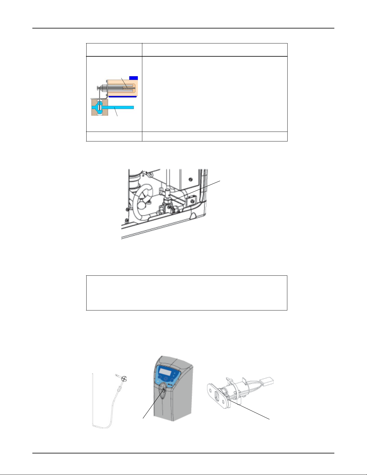
2.3.2 Chemical Disinfection and Cleaning
When the disinfection wand is connected to the chemical intake at the
front of the WRO unit, the three-way valve in the chemical intake unit
opens towards the chemical intake pump and the tank. The other end
of the wand is inserted into an external container with cleaning or disinfection solution. The chemical intake pump feeds the solution through
the wand into the tank. The optical sensor detects if the wand is connected or disconnected. When removed, the chemical intake pump
stops and the three-way valve closes towards the chemical connector
and instead allows for recirculation from tank through the chemical
intake unit, back to the tank, (during chemical disinfection, cleaning or
rinse). REVA also recirculates to the tank during some phases of
chemical disinfection, cleaning or rinse.
P/N 3027437 Rev. B
CAUTION
The chemical container must be located below the chemical
intake.
CAUTION
When requested by the WRO unit, remove the disinfection wand
from the chemical intake. Failure to remove the disinfection
wand can cause siphoning of the chemical solution from the bottle resulting in the tank overflowing chemical solution through the
back of the machine.
19
Technical Description
2.4 Components
2.4.1 Overview
WRO 300/300 H
20
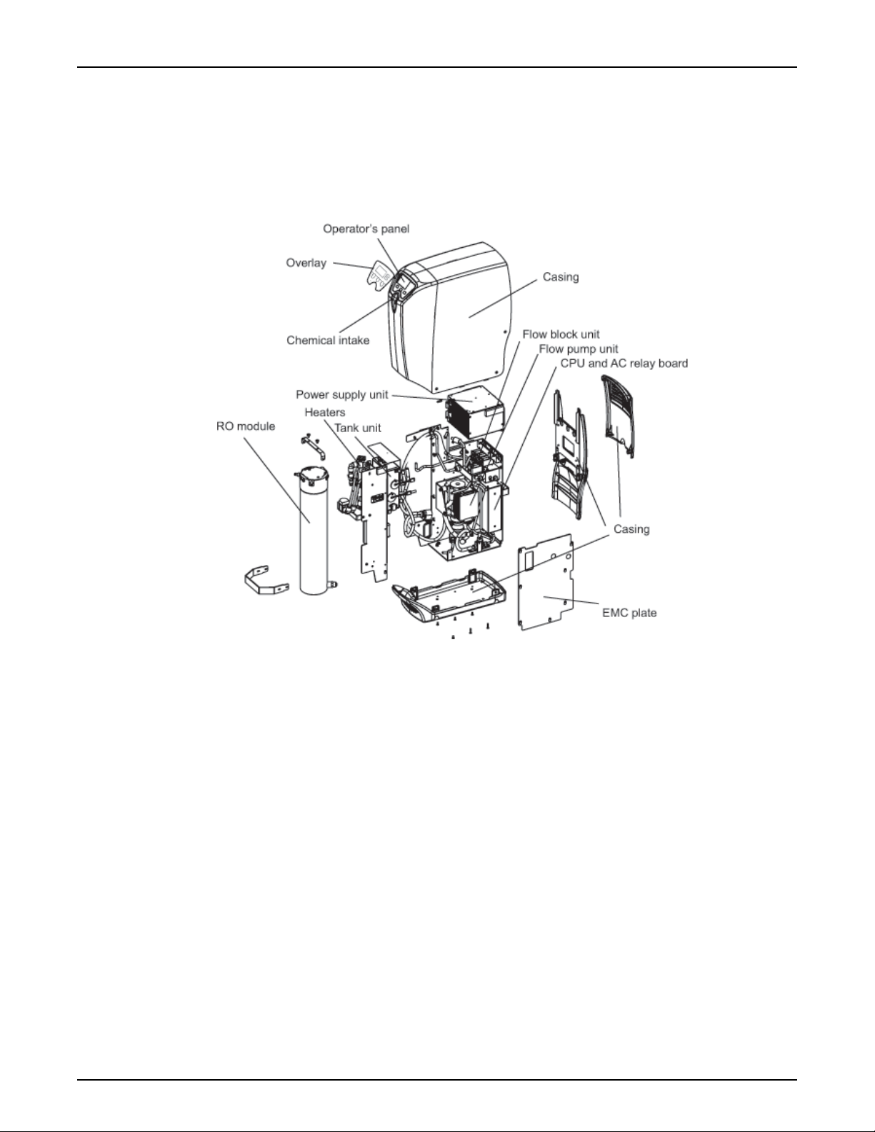
Fig.2.4 — The WRO 300 H unit overview
P/N 3027437 Rev. B
WRO 300/300 H
Detachable cover
Casing back
Casing top
Tray
Technical Description
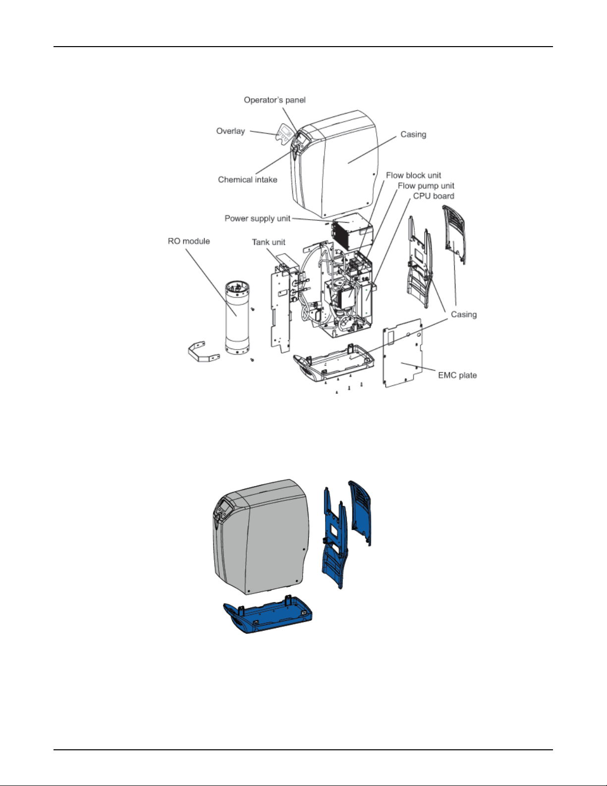
Fig.2.5 — The WRO 300 unit overview
2.4.2 Casing
The casing consists of four pieces as shown in the figure below.
Fig.2.6 — Casing
P/N 3027437 Rev. B
21
Technical Description
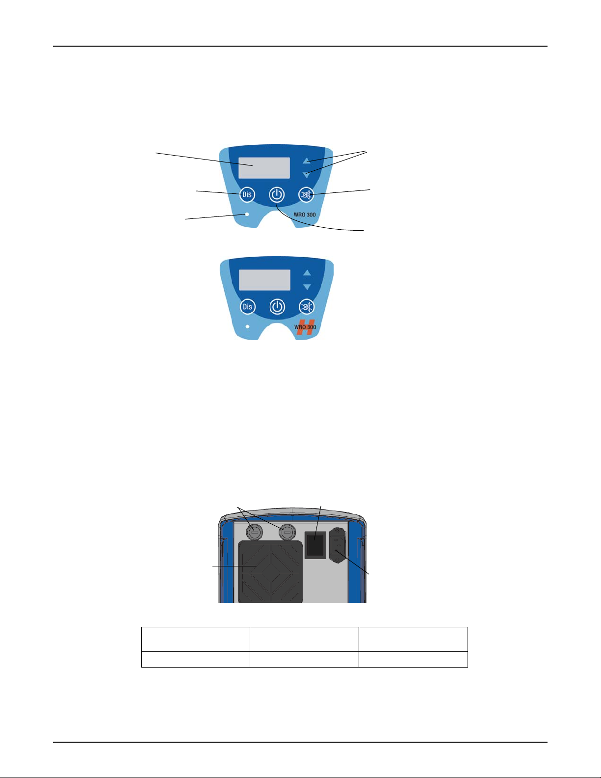
LCD
Arrow buttons
Mute button
Disinfection button
Run /Standby button
Lamp indication
Power ON
Power inlet
Mains power switch
Fan
Fuses
(only used in the WRO 300 H unit)
2.4.3 Operator Panel
The circuit board with the display, buttons, buzzer and LCD screen is
covered with an overlay. Overlay depends on model; WRO 300 unit or
WRO 300 H unit.
WRO 300/300 H
2.4.4 Power Supply Unit
The power supply unit adjusts automatically to the supplied voltage
(100, 115 or 220 to 240 VAC with 50 or 60 Hz). The internal voltage
supply is 24 VDC except for the heaters that are supplied with mains
power voltage, refer to Heat on page 87.
2.4.5 Fan
The fan cools the power supply unit.
Fuses for the WRO 300 H unit
1
1. Preset S32 must be changed, from GXP, to select the correct mains voltage.
Voltage
100 - 115 VAC 15 A SLO BLO ME20165
Fig.2.7 — Operator Panel
Fuse size MCP Order Number
22
P/N 3027437 Rev. B
WRO 300/300 H
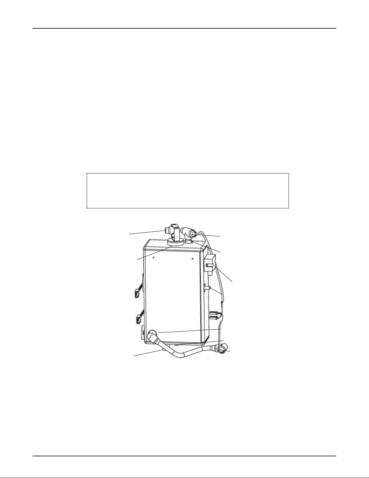
Level sensor 1 (High)
Level sensor 2 (Low)
Level sensor 3 (Empty)
Tank air vent
Feed water inlet
Reject water
Product water return
From chemical intake pump
To chemical intake
To RO pump (RO module)
Spray nozzle
Temperature sensor (T3)
Temperature sensor (T2)
(only WRO 300 H)
(only WRO 300 H)
2.4.6 Y Coupling and Product Water Loop
2.4.7 Tank
2.4.7.1 Tank Air Vent
Technical Description
The product water loop consists of two hoses from the WRO unit connected to the parallel connections at the Y coupling. The hose from the
third connection at the Y coupling is connected to the dialysis machine.
The tank is supplied with feed water from the feed water inlet and product return water and, if the water saving function is in use, also reject
water from the reject valve (REVA). The water is distributed to the RO
module or to the chemical intake pump (during disinfection).
The tank air vent connects the tank to the atmosphere. If the water
level reaches the tank air vent the excess water leaves the tank. To
avoid back contamination of the feed water supply there is an air gap
between the feed water at the top of the tank, above the tank air vent.
NOTE
The tank air vent outlet must be connected with an air gap to drain.
If a hose is connected to the tank air vent the hose should have a
constant slope.
P/N 3027437 Rev. B
Fig.2.8 — Tank
2.4.7.2 Spray Nozzle
The feed water enters the tank unit through a spray nozzle to spray the
walls of the tank.
23
Technical Description
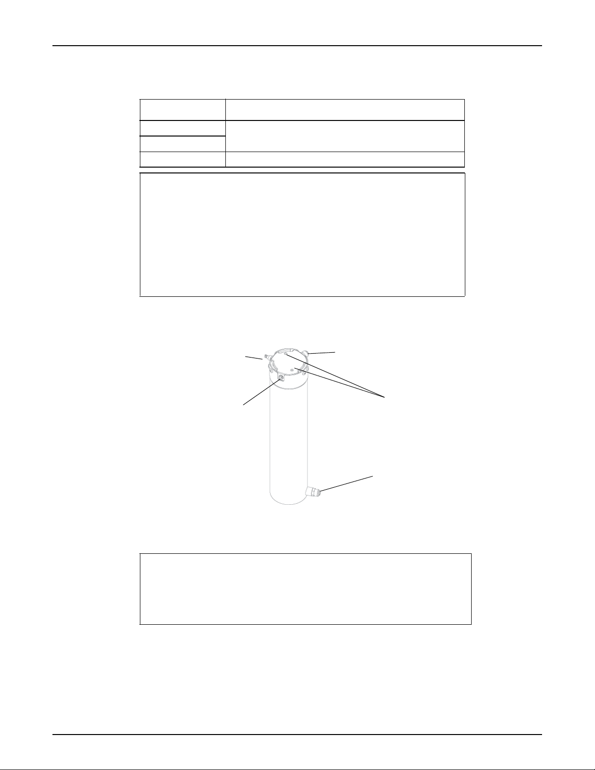
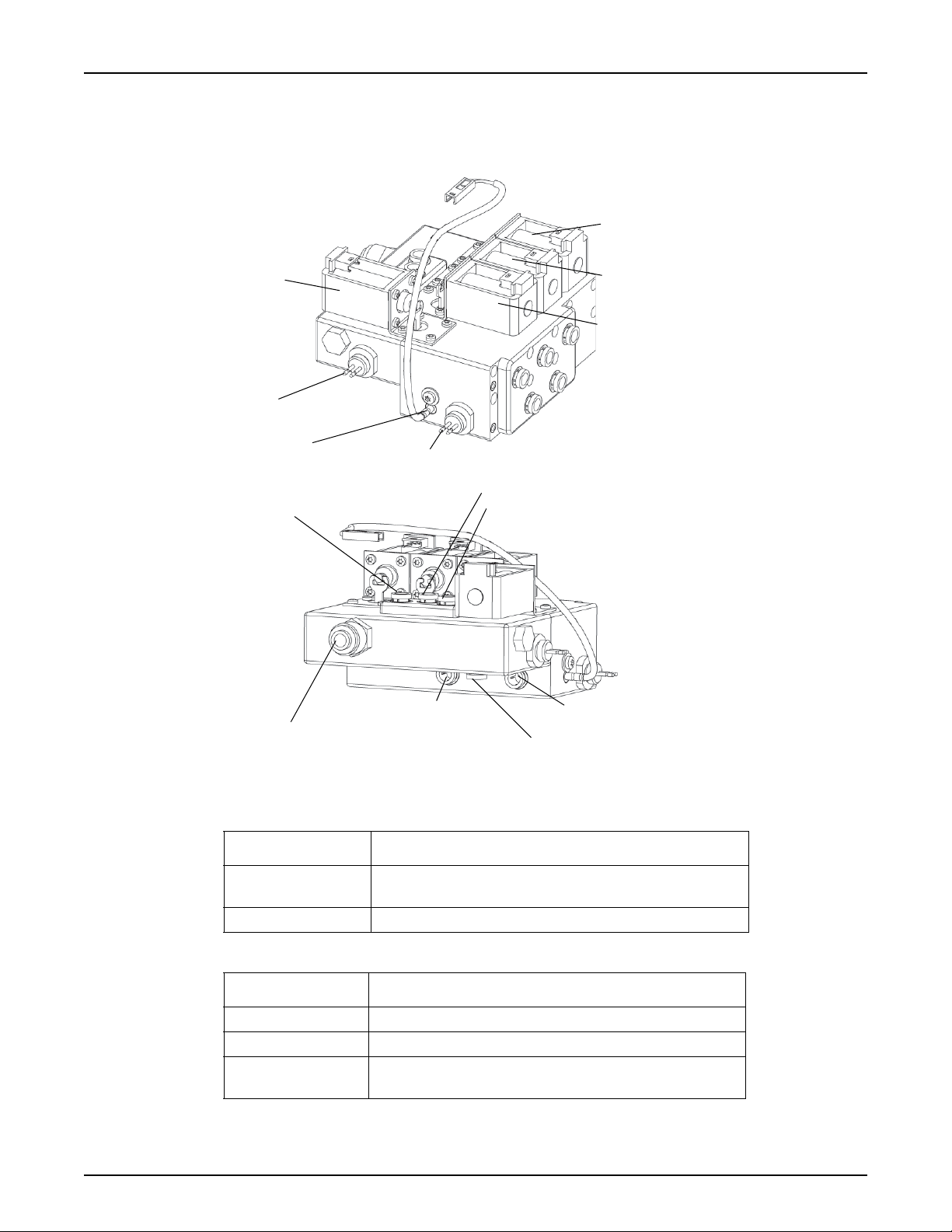
Feed water inlet
Product water outlet
Reject water outlet
Quick connector for
pressure gauge
2 holes, used to
remove the end plug
with withdrawing tool
2.4.7.3 Level Sensors
There are three level sensors in the tank to monitor the water level.
Level sensor Description
Low The high level sensor (LH) and the low level sensor (LL) are
High
Empty The empty level sensor (EL) is an optical sensor.
NOTE
• Avoid touching the optical sensors detection area with fingers and
do not expose it to dust. Optical sensors may be cleaned with a
gentle detergent or soap. Substances containing alcohol must not
be used.
• The float level switch can be permanently damaged if it is
dropped on a hard surface.
• To be able to use float level switches the program version must
be 4.0 or higher.
2.4.8 RO Modules
WRO 300/300 H
float level switches.
24
Fig.2.9 — RO module for the WRO 300 H unit
.
NOTE
• In a WRO 300 H unit, a new membrane element must be exposed
to at least one heat cycle before the rejection rate is acceptable.
• The membrane element must not be exposed to a pressure
exceeding 3 bar at temperatures above 45 °C.
P/N 3027437 Rev. B
WRO 300/300 H
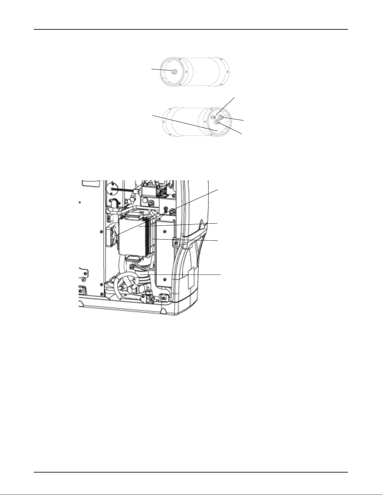
Feed water inlet
Product water outlet
Reject water outlet
Quick connector for
pressure gauge
There are 4 holes,
used to remove
the end plug
with withdrawing tool
Motor controller unit
Pump motor
Cooling fan
RO pump
2.4.9 Motor and RO Pump Unit
Technical Description
Fig.2.10 — RO module for the WRO 300 unit.
P/N 3027437 Rev. B
Fig.2.11 — RO pump
The RO pump creates the required pressure and flow for the reverse
osmosis process and circulates the water in the WRO unit. It is driven
by a 24 VDC brushless motor with a controller unit.
2.4.10 Cooling Fan
The pump motor and the motor controller unit are cooled by a separate, internal cooling fan.
25
Technical Description
Reject valve
Inlet valve
Bypass valve
Return overflow
Conductivity sensor (C2)
Temperature sensor (T1)
Conductivity sensor (C1)
valve (OFVA)
(BYVA)
(REVA)
(INVA)
From tank air vent
To needle valve
To product water outlet
From reject outlet on the RO module
Return overflow line to tank
Feed water to tank
Reject water line
2.4.11 Flow Block Complete
A number of the components required for the operation of the WRO
unit are located in the flow block.
WRO 300/300 H
26
Fig.2.12 — Flow block
Sensors Description
Conductivity sensors C1 in the feed water line and C2 in the product water line
measure the conductivity of the water.
Temperature sensor T1 measures the temperature in the product water line.
Valves Description
Reject valve (REVA) Three way solenoid valve, either diverts to drain or tank.
Inlet valve (INVA) Two way solenoid valve, opens and closes for feed water.
Bypass valve (BYVA) Two way solenoid valve, when open (active) the flow
bypasses the constant flow valve.
P/N 3027437 Rev. B
WRO 300/300 H
S
Product water loop
(Pressure)
Needle valve
Chemical intake
Chemical intake unit
Optical sensor
Disinfection wand
and connector
Technical Description
Valves Description
Return overflow valve
(OFVA)
Constant Flow valve This valve gives a steady flow of 1.2 ±0.1 l/min.
The spring-assisted solenoid valve (OFVA) has two functions:
• To maintain pressure in the loop. When deactivated
(run), the valve remains closed (= no flow) at pressures
below 0.25 MPa (2.5 bar). When the pressure increases
further, it gradually opens and lets water through.
• To relieve the pressure in the loop during certain
modes of operation. When activated, the valve opens
to the inlet water tank. This will minimize the flow from
the product water loop into the dialysis machine.
2.4.12 Needle Valve
Fig.2.13 — Needle valve
The needle valve controls the desired product water consumption (1.1
l/min) at a loop pressure of 1.5 bar.
NOTE
The setting of the needle valve affects the reject recirculation flow.
Turning the needle valve clockwise towards closed position will
reduce recirculation and increase module pressure.
2.4.13 Chemical Intake Unit
The chemical intake unit supplies the WRO unit with chemicals for disinfection or cleaning. The optical sensor detects if the disinfection
wand connector is inserted in the chemical intake.
P/N 3027437 Rev. B
Fig.2.14 — Chemical intake
27
Technical Description
2.4.14 CPU Board
The CPU board contains most of the electronics that control the function of the WRO unit.
2.4.15 AC Relay Board (only WRO 300 H)
The AC relay board contains the electronics that control the heater
rods.
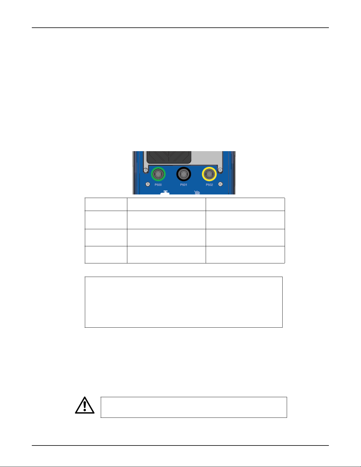
2.4.16 External Communication Connections
At the rear side of the WRO unit there are three external communication connections. These are used for external communication, logging
of data to a PC, and downloading upgraded software from a PC. The
required cables are optional and may be ordered from MCP.
WRO 300/300 H
Connection Function Description
P500
1
Green
P501
Black
P502
Yellow
1. Blue in older version of WRO unit.
External communication Currently not used.
Software communication Connection to PC.
External Signal/Remote Start Currently not used.
NOTE
• Only cables specified by MCP must be used when connecting the
WRO unit to external equipment.
• Be sure to use the correct cable type to the yellow connector
when an external alarm is connected, refer to Connection of
External Equipment on page 118.
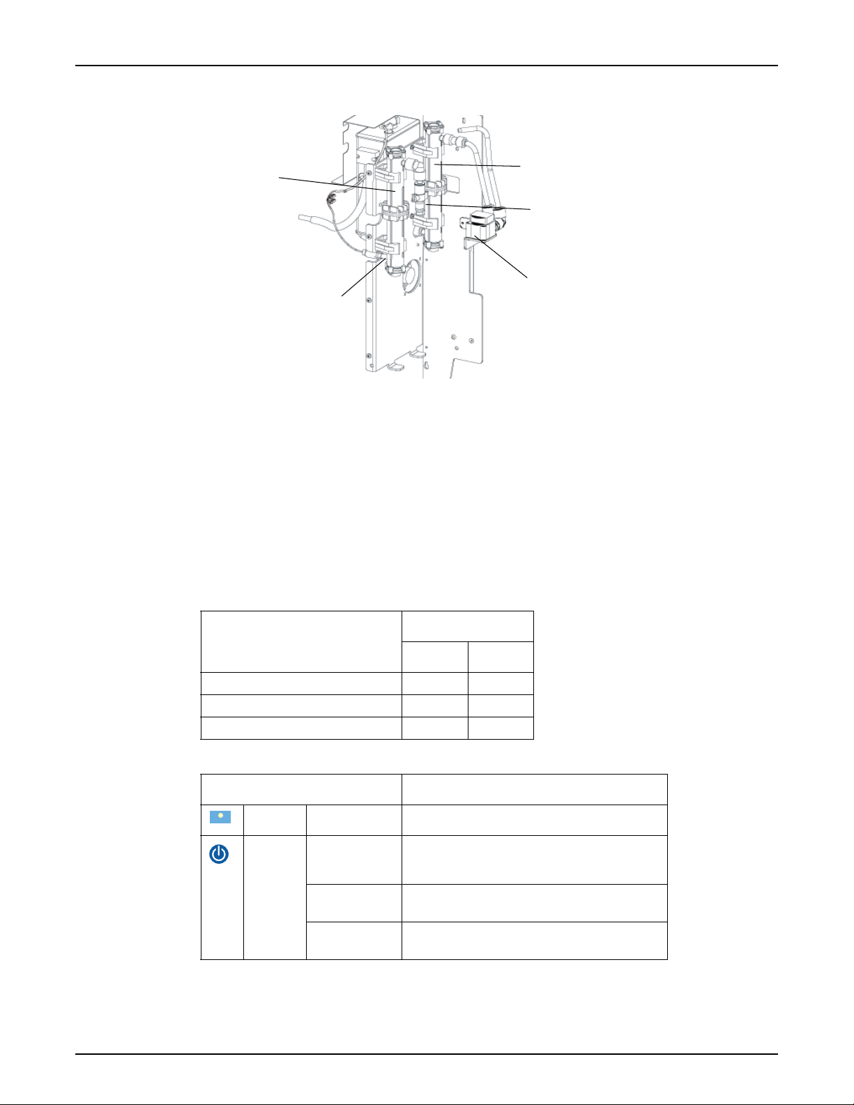
2.4.17 Heaters (only WRO 300 H)
The WRO 300 H unit is equipped with two heaters with different properties. The electrical connections are therefore different and marked
REJECT and PRODUCT on the AC relay board. Mount the reject
water heater to the left and the product water heater to the right as
seen in the figure below — if mounted incorrectly steam may come out
from the tank air vent.
28
CAUTION
Ensure that the heaters are mounted in the correct position.
P/N 3027437 Rev. B
WRO 300/300 H
Temperature sensor (T2)
Flow meter
Flow indicator
Heater REJECT
Heater PRODUCT
2.4.18 Mains Power Cable
Technical Description
Fig.2.15 — Heaters
Mains power cable is supplied with the RO and is a hospital grade, 15
Ampere rated capacity, detachable type cord.
2.5 Description of Indications
2.5.1 Light Indications
The light indications of the operator’s panel are described in the tables
below.
Time
Flash Indication
Slow flash 0.4 sec 2.0 sec
Medium flash 0.4 sec 0.4 sec
Fast flash 0.2 sec 0.2 sec
Indications Description
Green General
Green Steady
light
Slow flash
Fast flash
On Off
Indicates that the WRO 300 is energized.
Run mode, auto flush or manual flush in
progress.
The auto flush function is activated (only in
standby mode).
Insufficient feed water supply (only in run
mode).
P/N 3027437 Rev. B
29
Technical Description
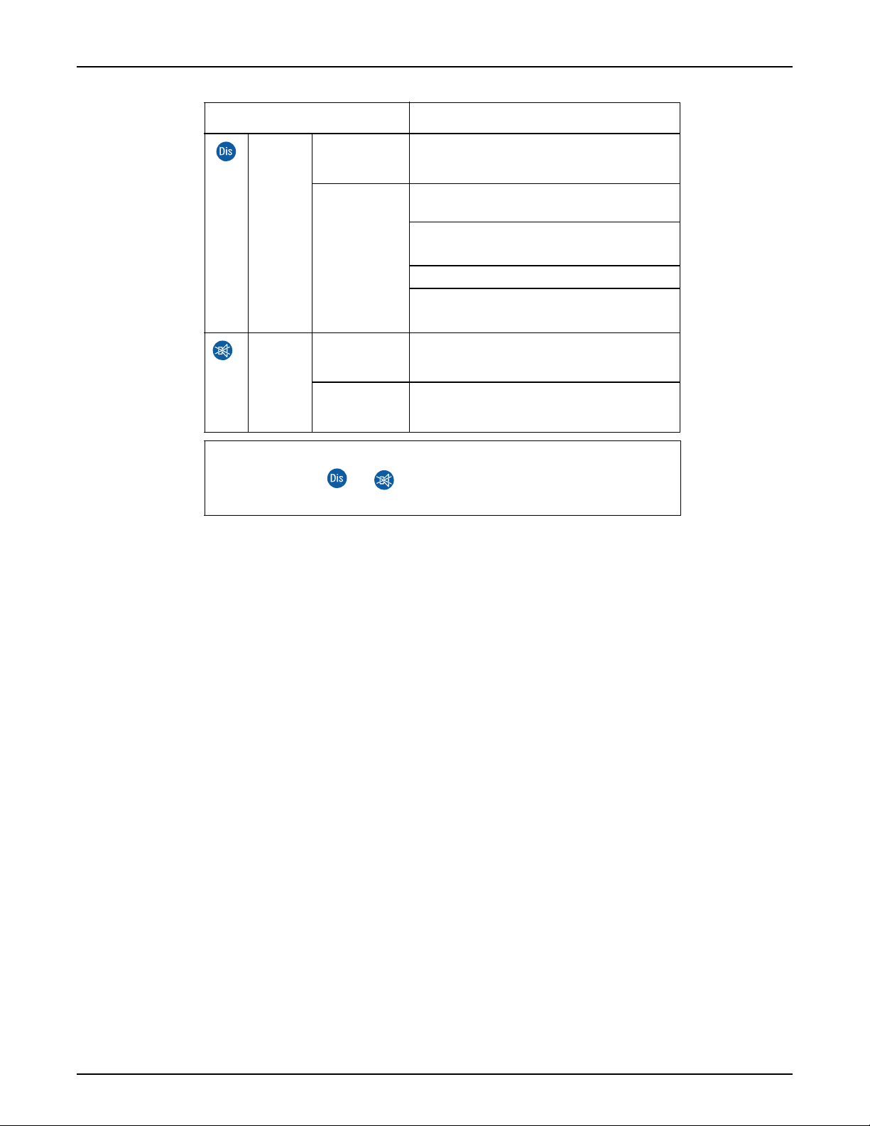
Indications Description
WRO 300/300 H
Yellow Steady
light
Medium
flash
Chemical disinfection or cleaning is in
progress.
The disinfection wand connector is inserted
into the chemical intake.
During selection of procedure in
SELECT or
CHEM SELECT.
The chemical intake phase is paused.
404 RINSE
Red Medium
flash
Steady
light
Forced rinse is required (
REQUIRED
Unconfirmed notification, info, alarm or stop
conditions are present.
Notification, info, alarm or stop condition has
been confirmed.
).
NOTE
Medium flash of or alerts the user to push the flashing button.
30
P/N 3027437 Rev. B
 Loading...