

Mar Cor Purification M4-2200, M4-13200 Maintenance Manual
M4-SERIES
WATER PURIFICATION MACHINES
M4-2200 – M4-13200
Operation
and Maintenance Manual
1238160 Rev. D
2233MMaay
y11

This page intentionally left blank
1238160 Rev. D 23May11

OPERATION AND MAINTENANCE MANUAL
M4-SERIES WATER PURIFICATION MACHINES
M4-2200 – M4-13200
TABLE OF CONTENTS
Page
CHAPTER ONE: GENERAL INFORMATION 1-1
Section 1.1 General Information and Principles of
1-3
Operation
1.2 Machine Nomenclature 1-7
1.3 Machine Permeate Quality 1-7
1.4 Materials and Features 1-7
1.5 Specifications for M4-Series Machines 1-8
CHAPTER TWO: INSTALLATION 2-1
Section 2.1 Mounting 2-3
2.2 Plumbing 2-3
2.3 Electrical 2-4
CHAPTER THREE: PREPARATION AND START-UP 3-1
Section 3.1 Pretreatment for Water Purification 3-3
3.2 Start-Up 3-4
CHAPTER FOUR: OPERATION AND MAINTENANCE 4-1
Section 4.1
4.2
Daily Log Sheets
Prefilter
4-3
4-3
4.3 Flushing 4-4
4.4 Cleaning 4-4
4.5 Sepralator Replacement 4-7
1238160 Rev. D A 23May11

CHAPTER FIVE: OPTIONAL ACCESSORIES 5-1
Section 5.1 Level Controls 5-3
5.2 Conductivity Meter 5-3
5.3 Autoflush 5-3
5.4 Filters and Water Softeners 5-5
CHAPTER SIX: TROUBLESHOOTING 6-1
APPENDIX A: RETURN MATERIAL AUTHORIZATION (RMA)
PROCEDURE
1238160 Rev. D B 23May11

M-Series Water Purification Machines
M-Series Water Purification Machines
M4-2200 – M4-13200
CHAPTER ONE:
DESCRIPTION
1238160 Rev. D 1 - 1 Description

M-Series Water Purification Machines
This page intentionally left blank.
1238160 Rev. D 1 - 2 Description
M-Series Water Purification Machines
1.1 General Information and Principles of Operation
These instructions give operating and maintenance details vital to the sustained
performance of the machine.
Reverse Osmosis (RO) is the removal of ionic, organic, and suspended
impurities from water by means of a membrane. Unlike a filter (“normal”
filtration), the feedwater or solution is separated into two streams by collecting
fluids from both sides of a pressurized membrane (“crossflow” filtration). A
semipermeable RO membrane, under sufficient pressure, allows passage of
purified water while rejecting and concentrating dissolved and suspended solids.
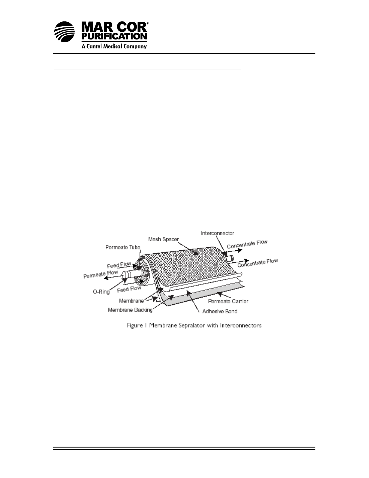
Mar Cor Purification manufactures a patented spiral-wound membrane package,
with a turbulent flow design. The membrane module (i.e. sepralator), also called
an element collects the purified water within a central tube (permeate tube), see
Figure 1.
Some operating definitions are provided to help you further understand your
machine:
PERMEATE RATE (PRODUCT WATER RATE) [QP]
This is the flow rate of purified water which has passed through the membrane
and out of the sepralator; expressed in gal/min (gpm) or gal/h (gph) [in metric,
liter/min (Lpm) or cubic meters/hour (m3/h). Specified permeate rates are
normally specified at 77°F (25°C).
1238160 Rev. D 1 - 3 Description

M-Series Water Purification Machines
CONCENTRATION
Concentration equals the Total Dissolved Solids (TDS) concentration of a
solution expressed as milligrams per liter (mg/L) or conductivity
(microSiemens/cm).
C
C
= Feed Concentration
f
Cp = Permeate Concentration
C
= Concentrate Concentration
c
= Average Concentration in machine
avg
SALT (IONIC) REJECTION:
This equals the percent of dissolved salt rejected by the membrane,
calculated from an average concentration over the membrane.
SALT (IONIC) PASSAGE:
This equals (100% - rejection) or the percent of dissolved salts passed
through the membrane.
CONCENTRATION RATE (WASTE WATER RATE) [Qc]:
This is the flow rate of water stream containing rejected solids to drain in
gpm or gph (pm or m3/h).
FEED RATE [Qf]:
This is the flow of incoming water in gpm or gph (Lp or m3/h). Feedwater
rate equals permeate rate plus concentrate rate.
An example of how to calculate salt rejection and recovery is given below:
1238160 Rev. D 1 - 4 Description
M-Series Water Purification Machines
Given the system case in Figure 2:
2
(C
Rejection = (C
(C
Passage = (C
(C
Recovery = (Q
(Q
Average Concentration (C
) = 123.5 mg/L TDS
avg
) 123.5 – (Cp) 6.2 x 100 = 95%
avg
) = 6.2 x 100% = 5.0%
p
) 123.5
avg
) 2 gpm x 100 = 33%
p
) 6 gpm
f
) = (Cf) 100 mg/L + (Cc) 146.9 mg/L
avg
) 123.5
avg
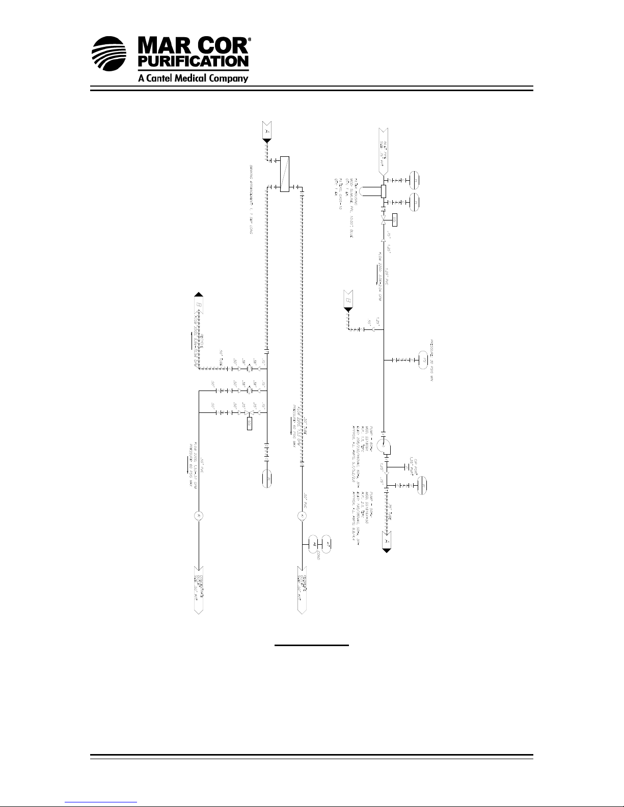
FLOW DESCRIPTION:
The feedwater passes through a replaceable 5-micron cartridge filter,
which removes bulk suspended solids. Filtered water then flows to the inlet
control valve. This solenoid-controlled diaphragm valve is wired to the
on/off switch and opens when the machine is turned on allowing water to
flow to the pump inlet. When the machine is turned off, the valve closes,
preventing non-turbulent flow through the sepralators, that would lead to
shortened membrane life.
The pump feeds water to the sepralator housings arranged in parallel and
serial combinations. An arrow on each element housing indicates the
direction of water flow. The water is sepralated by the membrane within
the elements and leaves the housings in two streams as permeate and
concentrate.
Permeate from each sepralator housing is collected in a common manifold.
A pressure relief valve is installed to alleviate excessive backpressure
build-up. The permeate then flows through a flow meter and to the outlet
point of the machine.
The concentrate leaves the last sepralator housing and flows to the flow
control center. At this point, the recycle valve channels a predetermined
amount of concentrate into the pump inlet. This achieves more efficient
water recovery while maintaining adequate crossflow through the
sepralators. The other two ports of the flow control center lead to the
concentrate valve and final pressure gauge. The concentrate valve has
three functions: It controls the amount of concentrate flowing to the drain; it
controls the pressure within the machine, and it helps control the system
recovery. An optional autoflush solenoid is added to the flow control center
with an additional tee. The concentrate then flows through a flow meter
and to the outlet point of the machine.
1238160 Rev. D 1 - 5 Description
M-Series Water Purification Machines
1238160 Rev. D 1 - 6 Description
Typical P&ID
M-Series Water Purification Machines
1.2 Machine Nomenclature
M-Series water purification are numbered in such a way as to indicate the
permeate flow and quality you can expect from the machine.
Example: M4-6600, 208, 6, 50-75
• M4 indicates the machine series
• 6600 indicates the rated permeate flow in gallons per day
• 208 indicates motor voltage
• 6 indicates 60 Hz
• 50-75 indicates the % recovery capability of the RO
1.3 Machine Permeate Quality
The permeate rejection performances are as follows:
M-Series machines use high rejection FASTEKu S4040 membrane, providing the
ultimate in high purity water.
1.4 Materials and Features
M-Series water purification machines have all the features necessary for safe,
continuous production of high purity water. Also, the M-series RO contains an
array of useful features for monitoring and data collection to help prolong
membrane life. This assumes good quality feedwater, adequate pretreatment
and regular operator attention, each shift or daily, to the operation of the system.
• 50% or 75% recovery
• Multi-stage centrifugal pump, SB construction (nickel-plated cast iron
*
castings, Noryl
stages, remainder stainless steel) typically not
recommended for operation below pH 5.8
• Base model electrical package includes NEMA-4X enclosure with a 115
VAC, 60 Hz or 230 VAC, 50Hz single-phase control circuit.
• Automatic inlet shutoff valve
• Pre-filter, post-filter, primary, and final pressure gauges
• Concentrate and permeate flow meters
• Gauges, valves, and rigid plumbing of stainless steel, brass, or plastic
• Membrane element housings, all 304 stainless steel, with PVC end caps
• 316 stainless steel concentrate and recycle valves
• All components in contact with the purified water (permeate) are either
non-leachable acceptable plastic (nylon, Noryl, polypropylene, PVC) or
stainless steel materials
• All high pressure fittings are 304 stainless steel
1238160 Rev. D 1 - 7 Description
M-Series Water Purification Machines
• Autoflush System – programmable, automated high velocity membrane
flushing for the longest membrane life; set at the factory and adjustable in
the field, includes a digital panel-mount timer, complete with push button
Manual Flush
• An electrical package that includes alarm delay shutdown for low inlet
pressure condition to prevent pump damage should pressure fall below 15
psig (1 bar)
• Conductivity monitor, panel-mounted, for permeate quality monitoring
• NEMA-4X fiberglass electrical enclosure
1.5 Specifications for M-Series Machines
1.5.1 Feedwater
TEMPERATURE:
35-77° (22-25°C) [Not to exceed 85°F (29°C) unless specifically designed for
higher temperatures]
INLET PRESSURE:
Minimum: 30 psig (2.1 bar)
Maximum: 60psig (4.1bar)
CHLORINE (CONTINUOUS FEED):
For FASTEK TLC membranes 0 ppm
OPERATING pH:
Softwater [less than 1 grain per gallon 3.0-10.0 (gpg) or 17 mg/L hardness]
Unsoftened water (contact factory 5.5-6.0 with water analysis)
PRE-FILTER:
5-micron HYTREX cartridge (see machine label for part number)
INLET CONNECTIONS:
¾-inch FNPT (IPS)
1238160 Rev. D 1 - 8 Description
M-Series Water Purification Machines
1.5.2 Permeate (Product Water) Flow Rate
Stated on the RO test report form (assumes no permeate back pressure, 2000
mg/L TDS maximum feed concentration, and rated temperature).
To estimate permeate output with back pressure, use the formula below:
Permeate Flow on Label x Operating Pressure – (Permeate Back Pressure)
Operating Pressure
Permeate Back Pressure Maximum: 60 psig (5.5 bar)
Permeate Outlet 3/4-inch FNPT
1.5.3 Concentrate Flow Rate
Stated on the RO test report form
Concentrate Outlet 3/4-inch FNPT
1.5.4 Typical Pure Water
Recovery 50-75%
1.5.5 Operating Final Pressure
Minimum 100 psig
Maximum 140 psig
1238160 Rev. D 1 - 9 Description

M-Series Water Purification Machines
1.5.6 Pump
Multi-stage centrifugal, approximately primary operating pressure of 100 psig
excluding line pressure.
1.5.7 RO Membrane Rejection
FASTEK TLC
Typical Ionic Rejection (TDS) 95-98%
Average Molecular Weigh Cutoff* 150 MW
*The molecular weight cutoff is based on the pore size of the membranes and the
nature (shape/size) of the organic molecule.
1238160 Rev. D 1 - 10 Description

NOTES:
M-Series Water Purification Machines
1238160 Rev. D 1 - 11 Description

M-Series Water Purification Machines
This page intentionally left blank.
1238160 Rev. D 1 - 12 Description

M-Series Water Purification Machines
M-Series Water Purification Machines
M4-2200 – M4-13200
CHAPTER TWO:
INSTALLATION
1238160 Rev. D 2 - 1 Installation Guidelines and Instructions

M-Series Water Purification Machines
This page intentionally left blank.
1238160 Rev. D 2 - 2 Installation Guidelines and Instructions
 Loading...