

Mar Cor Purification 23G 2 Element, 23G 6 Element, 23G 3 Element, 23G 4 Element, 23G 5 Element Operation And Maintenance Manual
...
Mar Cor Purification
23G-SERIES REVERSE OSMOSIS SYSTEM
Operation and Maintenance Manual
OS1157051 Rev. G 13July07

NOTICE
For personal and system safety, and for
optimum product performance, make sure
you thoroughly read and understand the
contents of this manual before installing,
using, or maintaining this product.
OS1157051 REV. G A 13-July-07

This page intentionally left blank.
OS1157051 REV. G B 13-July-07

A
TABLE OF CONTENTS
1.0 GENERAL INFORMATION
1.1 General Description
1.2 The Manual
1.3 Safety Summary
1.3.1 Read This Manual
1.3.2 Use Proper Power Connections
1.3.3 Device Labeling
1.4 Flow Description
1.5 Machine Nomenclature
1.6 Machine Permeate Quality
1.7 Machine Features
1.8 Specifications for 23G Machine
1.8.1 RO Feedwater Specifications
1.8.2 Permeate (Product Water) Flow Rate
1.8.3 Concentrate Flow Rate
1.8.4 Primary Operating Pressure
1.8.5 Pump
1.8.6 Reverse Osmosis Machine Rejection
1.9 Service Assistance
1.10 Medical Membrane Element Specification for Water Purification
2.0 INSTALLATION
2.1 Machine Location
2.2 Pluming
2.2.1 Inlet Plumbing
2.2.2 Valve for Clean-In-Place (CIP)
2.2.3 Concentrate Outlet Connection
2.2.4 Permeate Outlet Connection
2.3 Electrical
2.4 Machine Lockout
3.0 PREPARATION AND START-UP
3.1 Pretreatment for Water Purification
3.2 Initial Start-up
3.3 Daily Start-up and Operation Checklist
OS1157051 REV. G 13-July-07

4.0 ECM-100 OPERATION
4.1 ECM-100 General Description of Operation
4.2 ECM-100 Displays and Controls
4.2.1 System Status Lights – Left Column
4.2.2 System Status Lights – Right Column
4.2.3 Keypad – Control Section
4.2.4 Keypad – Menu Select Section
4.2.5 Liquid Crystal Display (LCD)
4.2.6 ECM-100 Passcode
4.2.7 Factory Settings Storage
4.2.8 Display Menus
4.3 ECM-100 Operation
4.3.1 Selecting Parameters and Changing Settings
4.3.2 Responding to an Alarm
4.3.3 ECM-100 Clean-In-Place (CIP Operation)
4.4 ECM-100 Display Screens
4.4.1 ECM Display Screen Hierarchy
4.4.2 Detail of Date and Time Operation (Menu 01)
4.4.3 Detail of Alarm Limits Operation (Menu 02)
4.4.4 Detail of Timer Presets Operation (Menu 03)
4.4.5 Detail of Accumulated Hours Operation (Menu 04)
4.4.6 Detail of Log Tables Operation (Menu05)
4.4.7 Detail of Calibration Operation (Menu 06)
4.4.8 Detail of Print Current Values Operation (Menu 08)
4.4.9 Detail of Metric/US Select Operation (Menu 09)
4.4.10 Detail of Perm High Conductivity Alarm Operation (Menu 10)
4.4.11 Detail of Factory Settings Operation (Menu 11)
4.4.12 Detail of Auto-On Tank Full Operation (Menu 12)
4.4.13 Detail of Comm Port Speed Operation (Menu 13)
5.0 MACHINE OPERATION AND MAINTENANCE
5.1 Daily Requirements
5.2 Weekly Requirements
5.3 Quarterly Requirements
5.4 Semi-annual Requirements
5.5 Annual Requirements
5.6 Flushing
OS1157051 REV. G 13-July-07
B

5.7 Step-Wise Cleaning
5.7.1 Installation of the 23G CIP
5.7.2 General Clean-In-Place Procedure
5.8 Sanitizing Using a CIP System
5.9 Membrane Element Cleaners and Sanitizers for 23G Machines
5.10 Pre-filter Replacement Procedure
5.11 Recording Performance Data
5.12 Preparing Machine for Movement
5.13 Membrane Element Replacement
5.13.1 Membrane Element Removal
5.13.2 Membrane Element Installation
5.14 Flow Control Adjustments
5.14.1 Leaks
5.15 Permeate Divert
5.16 Product Water Pressure Relief
6.0 OPTIONAL FEATURES AND ACCESSORIES
6.1 Level Controls
6.2 PH Controller/Sensor (ECM-100-pH)
6.3 Remote Alarm Interface - Six Channel
6.4 Printer/Computer Interface
6.4.1 Printer Interface
6.4.2 Computer Interface
6.4.3 Computer Connection
6.4.4 Printer Connection
6.4.5 Print Test
6.4.6 Print Functions
7.0 TROUBLESHOOTING
7.1 Emergency Alarm Bypass
7.1.1 Permeate Conductivity High or Rejection Low Alarms
7.1.2 Rejection Low Alarm Due to Failed Feed Conductivity Probe
7.1.3 Temperature High Alarm
7.1.4 pH Alarms
7.1.5 Pressure
7.1.6 Permeate Flow (Stuck at Zero)
7.2 General ECM-100 Reference/Troubleshooting Guidelines
7.2.1 Resetting the ECM-100
7.2.2 Check the Main Board Terminal Strip for Good Connections
7.2.3 Check the Relay Board Terminal Strip for Good Connections
7.2.4 Low Rejection Warning (Due to High Purity Feedwater)
7.2.5 Verifying the Temperature Circuitry of the Main Board
7.2.6 Difficulty Calibrating Permeate Conductivity
7.2.7 Information to Obtain Before Contacting Your Equipment Supplier
OS1157051 REV. G 13-July-07
C

8.0 23G SOFTWARE
8.1 Calibration Procedures – Version 2 Software
8.2 pH Calibration Procedure – Software Version V2
8.3 V2 Logic Board
8.4 Temperature Calibration Procedure – V2
8.4.1 Cleaning the Feed Conductivity Sensor
8.4.2 Calibrating the Temperature
8.5 Conductivity Calibration Procedure – V2
8.5.1 Measuring the Conductivity of Feed and Permeate Samples
8.5.2 Verifying the Percent Rejection Reading on the ECM-100
8.5.3 Displaying the Feed Conductivity on the ECM-100
8.5.4 Calibrating the Feed Conductivity
8.5.5 Restoring the Rejection Low Alarm Setting
8.5.6 Calibrating the Permeate Conductivity
8.6 Pressure Transducer Calibration Procedure – V2
8.7 Flow Calibration Procedure – V2
8.7.1 Calculating Permeate Flow Rate
8.7.2 Calculating Concentrate Flow Rate
8.7.3 Calibrating the Concentrate and Permeate Flow Rate Offsets
8.7.4 Verifying the Concentrate and Permeate Flow Rate Slopes
8.7.5 Calibrating the Concentrate and Permeate Flow Rate Slopes
9.0 RETURNED GOODS AUTHORIZATION PROCEDURE
10.0 SERVICE ASSISTANCE
11.0 SPARE PARTS LISTS
Valves
Prefilters
6-Channel Remote
Flow Block and Connectors
Pump and Motor Assemblies (Three-phase, 60 Hz)
Pump and Motor Assemblies (Three-phase, 50 Hz)
Pump and Motor Assemblies (Three-phase, 50 Hz)
Pump and Motor Assemblies (Single-phase)
Sensor
Electrical
Membrane Elements
4-inch Housing Spare Parts
Test Kits
Clamps
Miscellaneous
OS1157051 REV. G 13-July-07
D

Figure Title
1.1 Membrane Element with Interconnectors
1.2 System Schematic
1.3 Typical Flow Diagram for 23G Systems
2.4 Three-Phase Motor Wiring
4.5 ECM-100 Front Panel
4.6 23G Series ECM-100 Main Board Electrical Diagram
4.7 23G Series ECM-100 Relay Board Electrical Diagram
5.8 Brine Seal at the Exit End
5.9 Membrane Element Installation
5.10 Cross-Sectional View Membrane Element and Housing
5.11 Flow Control Manifold
7.11 ECM-100
Table Title
1.1 23G Model Number Matrix
1.2 Shipping Weights and Dimensions
2.3 Single-Phase Electrical Connections
2.4 Three-Phase Electrical Connections
4.5 ECM-100 Alarm Settings
4.6 ECM-100 Timer Settings
5.7 Dry Chemical Cleaners
5.8 Liquid Chemical Cleaners
6.10 Example of ECM-100 History Log
List of Figures
List of Tables
OS1157051 REV. G 13-July-07
E

23G-Series RO System
1.0 GENERAL INFORMATION
1.1 General Description
CAUTION:
When used as a medical device, Federal law restricts this device to sale
by or on the order of a physician, per 21 CFR 801.109 (b).
Your Mar Cor Purification 23G reverse osmosis machine is a durable
piece of equipment which, with proper care, will last for many years.
These instructions give operating and maintenance details vital to the
sustained performance of the machine.
Reverse Osmosis (RO) is the separation of one component of a solution
from another component by means of pressure exerted on a
semipermeable membrane. In other words, reversing the natural passage
of a liquid from a concentrate solution to a more dilute solution by using
external pressure. Removal of ionic, organic, and suspended/dissolved
impurities occurs during the RO process. Unlike a filter, which separates
by “normal” filtration, the membrane element separates using a process
called cross-flow filtration. Feedwater solution is separated into two
streams, permeate and concentrate, and collected from both sides of the
membrane. A semipermeable RO membrane, under sufficient pressure,
allows passage of purified water while rejecting and concentrating
dissolved and suspended solids.
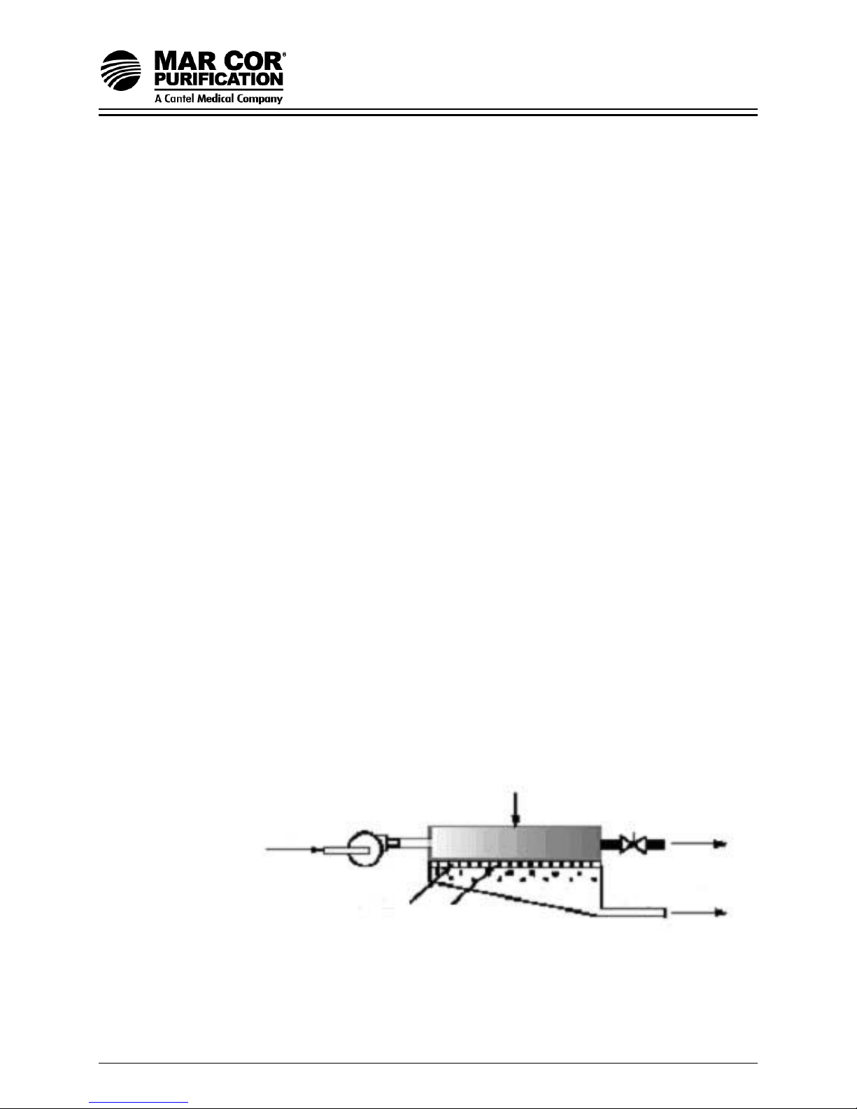
Mar Cor Purification manufactures a spiral-wound membrane package,
with turbulent flow design. This membrane element module collects the
purified water within a central tube (permeate tube), as represented in
Figure 1.1.
Brine Seal
Permeate Tube
Feed Solution
Permeate
Feed Channel Spacer
Membrane
Concentrate
Permeate Carrier
Membrane
Feed Channel Spacer
Outer Wrap
Figure 1.1 Membrane Element with Interconnectors
OS1157051 Rev G 1 13-July-07

23G-Series RO System
1.2 The Manual
This manual has been prepared to provide the operator with information
on the installation, operation, maintenance, and troubleshooting of 23G
Water Purification Systems.
The manual is supplemented with drawings and schematics for
clarification whenever possible.
1.3 Safety Summary
The safety summary does not contain all of the safety statements in the
manual. Other safety statements are included within the manual text and
are enhanced and defined as follows:
NOTE:
Indicates statements that provide further information and clarification.
CAUTION:
Indicates statements that are used to identify conditions or practices that could
result in equipment or other property damage.
WARNING:
Indicates statements that are used to identify conditions or practices that could
result in injury or loss of life. FAILURE TO FOLLOW WARNINGS COULD
RESULT IN SERIOUS INJURY OR DEATH TO HEMODIALYSIS PATIENTS OR
OPERATOR.
1.3.1 Read This Manual
Prior to operating or servicing this device, this manual must be read
and understood. Keep it and other associated information for future
reference and for new operators or qualified personnel near the
machine.
1.3.2 Use Proper Power Connections
Use proper wiring and connection methods as stated in this
manual.
1.3.3 Device Labeling
Do not, under any circumstances, remove any Caution, Warning, or
other descriptive labels from the devices until the conditions
warranting the label are eliminated.
Operating definitions are provided to help you further understand
your machine:
OS1157051 Rev G 2 13-July-07

23G-Series RO System
Permeate Rate [Product Water Rate (Qp)]
Permeate rate is the flow rate of purified water which has passed
through the membrane and out of the membrane element;
expressed in gal/min (gpm) or gal/hr (gph) [in metric, liter/min (Lpm)
or cubic meters/hour (m3/h)]. Specified permeate rates are
normally at 77°F (25°C).
Concentrate Rate [Waste Water Rate (Qc)]
Concentrate rate is the flow rate of water containing rejected solids
to drain in gpm or gph (Lpm or m3/h).
Feed Rate (Qr)
Feed rate is the flow rate of incoming water in gpm or gph (Lpm or
m3/h). Feedwater rate equals permeate rate plus concentrate rate.
Recovery
Recovery is the percentage (%) of feedwater converted to
permeate. For example, 75% recovery means that out of a given
feed rate, 75% is produced as pure water (permeate).
Concentration
Concentration equals the Total Dissolved Solids (TDS) of any
stream (feedwater, concentrate or permeate) of a solution
expressed as milligrams per liter (mg/L) or conductivity
(microSiemens/cm).
Cf = Feed Concentration
= Permeate Concentration
C
p
Cc = Concentrate Concentration
C
avg
= Average Concentration in Machine
Salt (Ionic) Rejection
Salt (Ionic) Rejection is the percent of dissolved salt rejected by the
membrane, calculated from an average concentration over the
membrane.
Salt (Ionic) Passage
Salt (Ionic) Passage is the percent of dissolved salts passed
through the membrane.
OS1157051 Rev G 3 13-July-07
23G-Series RO System
Primary Pressure (Pp)
Primary Pressure (Pp) is the pressure between the pump discharge
and the feed port of the first membrane element housing.
Final Pressure (Pf)
Final Pressure (P
) is the pressure between the concentrate outlet
f
of the last housing and the concentrate valve.
Pre-filter Pressure (P
Pre-filter Pressure (P
)
pre
) is the water pressure entering the pre-filter.
pre
Post-filter Pressure (P
Post-filter Pressure (P
)
post
) is the water pressure leaving the pre-
post
filter.
Membrane Elements
Membrane elements are the key to reverse osmosis. Interleaved
layers of semipermeable membrane, spacer and permeate carrier
spiraled around a central permeate tube make up the element. The
spacer allows for movement of the concentrate past the membrane,
and the permeate carrier carries the pure water out of the
membrane element. The elements that Mar Cor Purification uses
are spiral-wound membrane elements with a turbulent flow design.
The membrane element collects the permeate water within the
central tube, called the permeate tube.
Recovery 75%
100 mg/L
Feed
OS1157051 Rev G 4 13-July-07
C
avg
Pump
24 gpm
(C
(Q
)
f
)
f
Membrane
Porous
Backing Material
Figure 1.2 System Schematic
375 mg/L
6 gpm
8.3 mg/L
18 gpm
)
(C
c
Concentrate
)
(Q
c
(C
)
p
Permeate
)
(Q
p

23G-Series RO System
An example of how to calculate salt rejection and recovery:
Average Concentration (C
2 2
Rejection = (C
(C
Passage = (C
(C
Recovery = (Q
(Q
) - (Cp) x 100 250 - 6.2 x 100 = 97.5%
avg
) 250
avg
) x 100 6.2 x 100 = 2.5%
p
) 250
avg
) x 100 6 gpm x 100 = 75%
p
) 8 gpm
f
) = (Cf) + (Cc) 100 mg/L + 400 mg/L = 250 mg/L TDS
avg
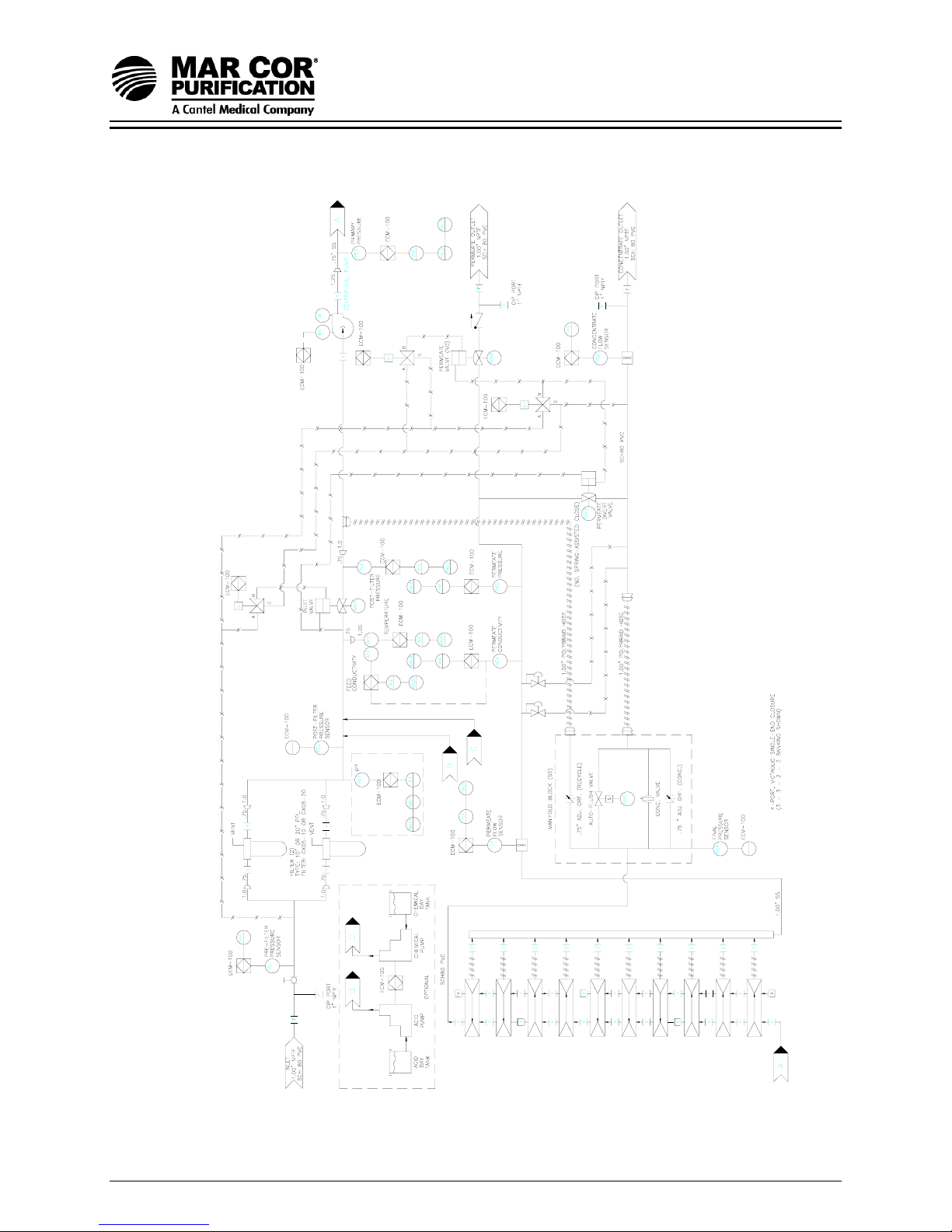
1.4 Flow Description
The pretreated feedwater passes through a disposable 5 micron cartridge
filter (pre-filter) which removes suspended solids. Filtered water then flows
to the inlet control valve. This solenoid-actuated valve is controlled by
Enhanced Controller/Monitor (ECM-100) and opens when the machine is
turned on, allowing water to flow to the pump inlet. When the machine is
turned off, the valve closes, preventing laminar flow through the
membrane element, which would lead to shortened membrane life.
The pump feeds water to the membrane element housings in a series
and/or parallel configuration, depending upon the design flow rates. The
direction of water flow is indicated by an arrow on each membrane
element housing.
Permeate from each membrane element housing is collected at the
permeate manifold where a common check valve prevents backflow into
the membrane elements. A pressure sensor is provided to allow the ECM100 to monitor excessive backpressure and initiate an immediate alarm
and machine shutdown should the setpoint be exceeded. Permeate is
directed through a turbine flow sensor and contacts a conductivity sensor
before reaching the outlet point of the machine.
OS1157051 Rev G 5 13-July-07

23G-Series RO System
The concentrate leaves the last membrane element housing and flows into
the manifold block. This concentrated water is then divided into recycle
and concentrate streams. The recycle portion mixes with the feedwater by
returning to the inlet piping, allowing higher machine recovery while still
maintaining adequate crossflow through the membrane elements. The
concentrate valve on a 23G machine is used to increase the concentrate
flow rate for flushing. The normal concentrate flow rate is controlled by the
concentrate orifice. The concentrate valve or orifice has three functions: it
controls the amount of concentrate flowing to the drain; it controls the
pressure within the machine; and it helps control system recovery. A
solenoid-controlled Autoflush valve is also provided in the concentrate line
to provide periodic intervals of increased drain flow rate controlled by the
ECM-100. The concentrate portion leaving the manifold block is directed
through a turbine flow sensor before reaching the outlet point of the
machine.
OS1157051 Rev G 6 13-July-07
23G-Series RO System
Figure 1.3 Typical Flow Diagram for 23G Systems
OS1157051 Rev G 7 13-July-07
23G-Series RO System
1.5 Machine Nomenclature
Mar Cor Purification water purification machines are numbered in such a
way as to indicate the permeate flow and quality you can expect from the
machine. The nomenclature (model number) of your machine is shown on
the serial number label on the side panel of the machine.
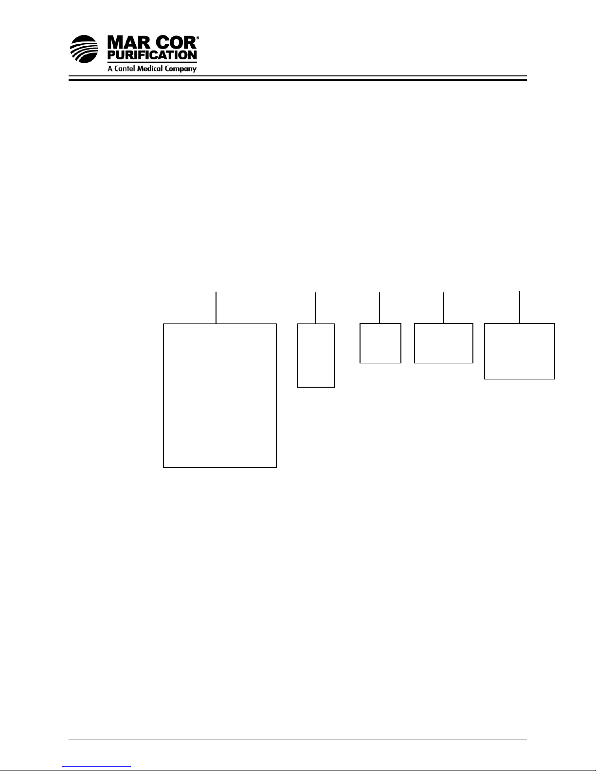
Table 1.1
23G Model Number Matrix
RO, 23G XXXX,
XXX, X, XX, XXXX
Rated Permeate Flow
GPD
3000
4500
6000
7500
9000
10500
12000
13500
15000
16500
Volts
208
230
460
380
Hertz
6=60
5=50
Recovery
50%
75%
Options
Single
Phase
W/Casters
1.6 Machine Permeate Quality
23G machines use high rejection, polymeric membrane, providing the
ultimate in high purity water.
OS1157051 Rev G 8 13-July-07

23G-Series RO System
1.7 Machine Features
Mar Cor Purification 23G Series machines contain an array of useful
standard features to provide additional system safety and reliability, to
simplify system monitoring and data collection, and to ensure the longest
membrane life.
Standard features include:
• 50% and 75% recovery models available.
• Multi-stage centrifugal stainless steel pump, submersible design.
• Enhanced controller/monitor (ECM-100); includes parameter
display, alarms, and machine status indicators.
• Automatic inlet shut-off valve.
• Common check valve in the permeate line to prevent backflow.
• Pre-filter housings and 5 micron cartridge filters.
• Pre- and post-filter pressure indication.
• Primary and final pressure indication.
• Permeate backpressure indication.
• Product water divert.
• Product water pressure relief.
• Concentrate and percent rejection indication for permeate quality
and membrane performance monitoring.
• Temperature indication for feedwater temperature monitoring.
• Membrane element housings made of all 304 stainless steel.
• Autoflush - programmable periodic high velocity membrane flushing
to maintain long membrane life. Set at factory and adjustable in the
field.
• Inlet low pressure alarm automatically shuts off the machine to
prevent pump damage, should inlet pressure fall to an inadequate
level.
• Components in contact with the RO water (permeate) are made of
either inert plastic (nylon, poly-ethylene, Noryl*, polypropylene,
PVC, EPDM, Nitrile) or stainless steel materials.
• Memory for more than 400 sets of historical operating data
(generated by approximately 2.5 full months of continuous
operation).
• Comprehensive alarm package, with adjustable limits and common
time-out, to ensure safety and proper operation. Alarm is both
visual and audible. Alarms include:
OS1157051 Rev G 9 13-July-07

23G-Series RO System
• high/low primary pressure (immediate shutdown on primary high
pressure)
• low inlet post-filter pressure
• high permeate pressure (immediate shutdown)
• high/low pH
• high temperature
• high permeate conductivity
• low permeate conductivity
• low permeate flow
• low percent rejection
• high pre-filter pressure drop
• high membrane pressure drop
NOTE:
All alarms except high primary pressure, high permeate pressure, and
high temperature are ignored in Clean in Place (CIP) mode.
*Noryl is a trademark of General Electric Company.
OS1157051 Rev G 10 13-July-07

23G-Series RO System
Specifications for 23G Machines
1.7.1 RO Feedwater Specifications
The rated flow for all machines in this section is based upon the
following feedwater specifications. Limits should not be exceeded
without consulting the factory.
Inlet Pressure Rated; 30 psi (2.1 bar)
Maximum; 60 psi (4.1 bar)
Minimum; 20 psi (1.4 bar)
Temperature1 35-77°F (2-25°C) not to exceed 85°F (29°C)
Langelier Saturation Negative 0.1
Index of Concentrate
2
Continuous Free Chlorine (mg/L)3 Less than 0.1 ppm
Silt Density Index4 Less than 3
Iron 0 ppm
Other Impurities
5
Pre-filter 5 micron cartridge(s)
Inlet Connection Thread 1-inch Female National Pipe (FNPT)
1. Continuous operation over 85°F (30°C) may cause
permanent decline in the membrane element performance.
Actual permeate flow rates typically increase/decrease by
1.4% for each 1°F change in temperature. For other
temperatures, use “Temperature Factor Chart” (Technote
113) to determine permeate rate. Contact authorized
equipment supplier if feedwater is outside these parameters.
OS1157051 Rev G 11 13-July-07

23G-Series RO System
2. The Langelier Saturation Index (LSI) of the concentrate must
be negative to minimize the possibility of calcium scale
formation on the membrane surface. Refer to ASTM
Standard D3739.
3. Chlorine should be removed prior to the PA membrane in
order to prolong the functional life of the membrane element.
Microbiological growth will not affect the membrane itself, but
may cause fouling and significant permeate flow rate
decline. See Membrane Specification Sheet for additional
information.
4. Maintenance of feedwater Silt Density Index (SDI) as noted
would minimize membrane fouling and extend cleaning
intervals. Treatment of feed waters with higher SDI values is
possible with more frequent cleaning and/or filter changes.
Refer to ASTM Standard D4189.
5. Components such as silica, barium, manganese, strontium,
etc., must be below saturation in the concentrate. Contact
your equipment supplier for clarification if unsure.
6. It is recommended that an adjustable pressure regulator be
installed just prior to the RO in order to allow adjustment of
inlet pressure to RO. Regulator must be able to provide
adequate flow to RO.
1.7.2 Permeate (Product Water) Flow Rate
As stated on the serial number label (assumes no permeate
backpressure, 1000 mg/L TDS maximum feed concentration, and
rated temperature).
To estimate the permeate output with backpressure, use the
formula below:
(Permeate Flow on Label) x (Operating Pressure) - (Permeate Backpressure)
(Operating Pressure)
Maximum Permeate Backpressure: 60 psi (4.1 bar)
Permeate Outlet: 1-inch female NPT
1.8.3 Concentrate Flow Rate
Factory set as stated on serial number label.
Concentrate Outlet 1-inch female NPT
OS1157051 Rev G 12 13-July-07
23G-Series RO System
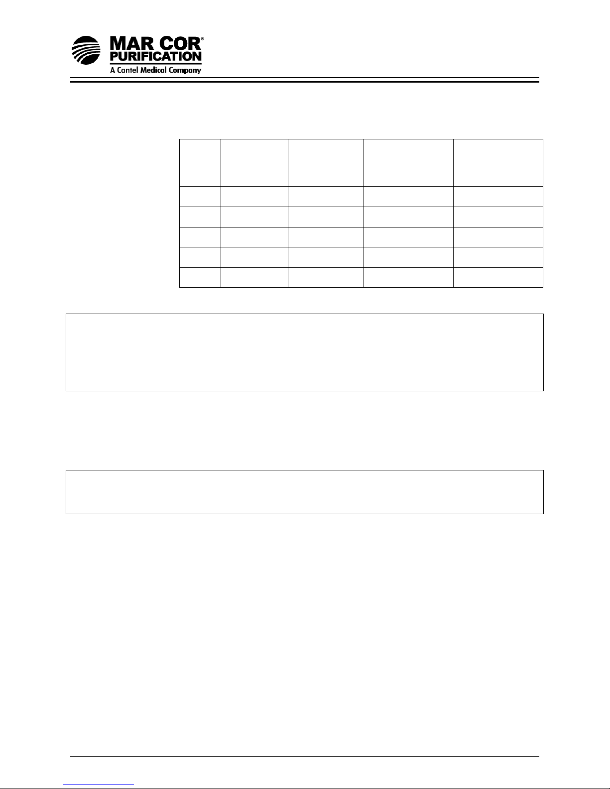
1.8.4 Primary Operating Pressure
Motor
(Hp)
Frequency
(Hz)
Pump
Model
Minimum
Boost Primary
Pressure (PSI)
Maximum
Boost Primary
Pressure (PSI)
3 60 QS1818VB 120 270
5 60 QS2818VB 100 250
7.5 60 QS2825VB 170 350
3 50 QS1828VB 120 280
5 50 QS2825VB 100 250
NOTE:
Boost pressure = (primary pressure — post-filter pressure).
NOTE:
Primary and final pressure parameters may vary depending upon machine design and
installation conditions.
1.8.5 Pump
Multi-stage centrifugal, approximate primary operating pressure of
200 psi (13.8 bar) excluding line pressure.
NOTE:
Actual operating pressure may vary depending upon machine design and installation
conditions.
1.8.6 Reverse Osmosis Machine Rejection
Typical Ionic Rejection (TDS) 95 - 99%
Average Molecular Weight Cutoff* 150 MW
*The molecular weight cutoff is based on the pore size of the
membranes and the nature of the organic molecule (size/shape).
OS1157051 Rev G 13 13-July-07

23G-Series RO System
Table 1.2 Approximate Shipping Weights and Dimensions
Model Number Shipping Dimensions Shipping Weight
23G 2 Element 65” D x 34” W x 78” H
(165 cm D x 86 cm W x 200 cm H)
23G 3 Element 65” D x 34” W x 78” H
(165 cm D x 86 cm W x 200 cm H)
23G 4 Element 65” D x 34” W x 78” H
(165 cm D x 86 cm W x 200 cm H)
23G 5 Element 65” D x 34” W x 78” H
(165 cm D x 86 cm W x 200 cm H)
23G 6 Element 81” D x 34” W x 78” H
(205 cm D x 86 cm W x 200 cm H)
23G 7 Element 81” D x 34” W x 78” H
(205 cm D x 86 cm W x 200 cm H)
23G 8 Element 81” D x 34” W x 78” H
(205 cm D x 86 cm W x 200 cm H)
23G 9 Element 81” D x 34” W x 78” H
(205 cm D x 64 cm W x 200 cm H)
23G 10 Element 81” D x 34” W x 78” H
(205 cm D x 64 cm W x 200 cm H)
23G 11 Element 90” D x 34” W x 88” H
(228 cm D x 64 cm W x 224 cm H)
655 lbs
(298 kg)
685 lbs
(311 kg)
725 lbs
(330 kg)
815 lbs
(370 kg)
845 lbs
(384 kg)
925 lbs
(420 kg)
1025 lbs
(466 kg)
1060 lbs
(480 kg)
1100 lbs
(500 kg)
1200 lbs
(545 kg)
1.9 Service Assistance
If service assistance is required, take the following steps:
1. Consult the Troubleshooting Section of this manual (Section 7.0). If
the problem cannot be identified and corrected by any of the
procedures found in the troubleshooting section, then
2. Call your equipment supplier.
Prior to making the call, have the following information available:
Machine installation date
Model number (found on right-hand side of front panel)
Serial number (found on right-hand side of front panel)
Daily log sheets
Current operating parameters (i.e., flow, operating pressures, pH,
etc.)
Description of the problem
Current software version (from memory chip on inside of door)
OS1157051 Rev G 14 13-July-07

23G-Series RO System
1.10 Medical Membrane Element Specification
NaCl rejection: 99.0% Average (98.0% minimum)
Based on a 2,000 mg/L NaCl solution at 225 psig (1,551 kPa) operating
pressure, 77 °F (25 °C), pH 7.5, 15% recovery, after 24 hours. Individual
element flow may vary 15%.
Design Parameters
Maximum pressure: 300 psig (2070 kPa)
Typical cleaning: <200 psig (1450 kPa)
Maximum temperature
Operating: 90 °F (32 °C)
Cleaning: 85 °F (29 °C) *
Operating pH: 5.0- 10.0
Cleaning pH: 2.0 - 11.5
Feed NTU: < 1
Feed SDI: < 3
Chlorine tolerance: 1,000 ppm-hours Dechlorination recommended
Maximum Delta P: 10 psig (69 kPa) per element
* CAUTION: Operating the system at above 85°F during cleaning can cause significant
pump damage.
Element Performance Feed Concentration
Ion mg/L % Rejection
Sodium 68.0 99.4
Calcium 80.0 99.8
Magnesium 21.0 99.8
Potassium 4.1 99.4
Sulfate 163.0 99.8
Bicarbonate 132.0 99.3
Chloride 51.0 99.4
Silica 9.3 92.0
TDS 528.0 99.4
Based on a mixed salt feed solution at 225 psig (1,551 kPa) operating pressure,
77 °F (25 °C), pH 7.5, 15% recovery, after 24 hours.
OS1157051 Rev G 15 13-July-07

23G-Series RO System
2.0 INSTALLATION
2.1 Machine Location
At least 45 inches (114 cm) of space should be allowed above the
membrane element housings for easy removal and loading of membrane
elements. Provide adequate workspace on sides and front for easy
access.
NOTE:
If necessary, housings may be detached from the frame for membrane
element removal due to space restrictions around the machine.
2.2 Plumbing
2.2.1 Inlet Plumbing
The feedwater source should be plumbed to the 1-inch FNPT inlet
point on the 23G machine. If the inlet pressure is in excess of 60
psi (4.1 bar) or fluctuates by more than 5 psi (0.3 bar), a pressure
regulator should be installed ahead of the connection. A low
pressure sensor is installed on every 23G machine to protect
against low inlet pressure. The 23G should not be installed where
the feedwater dynamic inlet pressure is less than 20 psi (1.4 bar). If
inlet pressure is less than 20 psi (1.4 bar), a booster pump must be
installed ahead of the connection.
2.2.2 Valves for Clean-In-Place (CIP)
All 23G units have separate CIP connections. Valves should be
installed on both the main and inlet cleaning connections of the inlet
stream. The permeate outlet and concentrate outlet plumbing
streams include factory installed manual shutoff valves.
CAUTION:
Do not operate the machine with all concentrate and permeate
connections closed. Severe damage to the unit may result.
2.2.3 Concentrate Outlet Connection
Connect a 1.0-inch hose or pipe to the concentrate outlet and run to
an open drain. To avoid drainage to the machine during nonoperation, the concentrate outlet plumbing should be placed at a
height which is at least equal to the height of the machine. A siphon
break may also be installed in the concentrate line for added
protection. The concentrate outlet hose or pipe can be any length,
and the diameter should match the outlet of the machine.
OS1157051 Rev G 16 13-July-07

23G-Series RO System
NOTE:
Soft, flexible hose can be used, but must be installed in a manner
which prevents “kinks” or other restrictions that will increase back
pressure and reduce permeate flow rate to the drain.
2.2.4 Permeate Outlet Connection
Connect a 1.0-inch I.D. hose or pipe to the permeate outlet and run
to the storage tank (if applicable) or distribution loop (after
distribution loop, points of use).
The pure water (permeate) should be transported to the point-ofuse via noncorroding inert-type tubing pipe or hose. Examples are:
food grade flexible nylon tubing, stainless steel tubing or PVC
piping.
NOTE:
Soft, flexible hose can be used, but must be installed in a manner
which prevents “kinks” or other restrictions that will increase back
pressure and reduce permeate flow rate to the drain.
NOTE:
Do not use copper or galvanized tubing or piping to carry the
permeate. Only food grade materials and/or appropriate NSF
materials should be used.
2.3 Electrical
The ECM-100 controls and monitors the operation of the 23G, requiring a
dedicated 115/230 VAC 60/50Hz, 15/10 A, 220 VAC, single-phase power
source. All control output devices (motor starter, solenoid valves, chemical
pumps) draw power from this source (through ECM-100 relay outputs) in
addition to the ECM-100 itself. Refer to Figures 2.3 and 2.4 for connection
details and ECM-100 inputs and outputs.
The ECM-100 monitors system-operating parameters for alarm conditions
to safeguard the machine’s operation. User variation of the alarm limits
and timer presets (set at the factory) are possible by accessing the
appropriate function from the system operations menu and following the
respective directions for making the changes.
The 23G pump is wired at the factory to an IEC overload protection
magnetic motor starter that is controlled by the ECM-100.
The procedure for connecting the electrical wiring for installation of the
23G follows:
OS1157051 Rev G 17 13-July-07

23G-Series RO System
1. Connect the ECM-100 power cord to a properly grounded 15 A,
115 VAC/60Hz or 10 A 220 VAC/50Hz, single-phase outlet. An
appropriate termination should be installed on the electrical cord for
220 VAC service. Surge protection for single-phase service is
recommended.
The ECM-100 relay output contacts are rated to handle a control
ON relay-type circuit. V2 relay boards, supplied in all 23G machines
after November 1998, are designed to handle a maximum load of
3.0 AMPS. The current requirements of all output devices (such as
a remote alarm horn and light) must be within these limits.
The power cord of the ECM-100 should be connected to a power
receptacle tied to a “protective earth” ground to ensure a safe,
common ground for the entire 23G unit, including the three-phase
motor. DO NOT remove the grounding wire from the pump casing,
the unit frame or a power supply grounding terminal.
WARNING:
ALL SUPPLY CIRCUITS MUST BE DISCONNECTED BEFORE OBTAINING
ACCESS TO TERMINALS.
2. Separate power supplies are required for CIP and main pump.
3. Connect the magnetic motor starter to the proper voltage, phase
and cycles to match motor voltage and phase. Install the wires as
indicated in Table 2.3 (single-phase) or Figure 2.4 and Table 2.4
(three-phase). The overload trip point on the pump motor starter
may need to be adjusted slightly to match the actual voltage being
provided. Check the tag on the motor starter indicating the factory
wiring. A separate, fused disconnect for the motor wiring with the
proper overload and short-circuit protection for the Hp and amp
draw of the motor is required. Bussmann Low-Peak Yellow LPSRKSP fuses or equal are recommended for the disconnect.
NOTE:
Field wiring must comply with all applicable national and local electrical
codes.
OS1157051 Rev G 18 13-July-07

23G-Series RO System
2.4 Machine Lockout
In general, the machine should be operated in AUTO mode in which
conditions are confirmed electronically. The ECM-100 terminal strip has
terminals available for linking other treatment equipment, such as a
softener, to the operation of the 23G machine or monitoring the status of
other equipment. The status of this equipment is indicated by LightEmitting Diode (LED) lights on the ECM-100. When operating in HAND
mode, it is the operator’s responsibility to ensure adequate feedwater
supply and storage tank capacity.
Lockouts are ignored in HAND mode, such as full tank level, etc. CIP
mode ignores temperature and pH alarms.
The Pretreatment Lockout input can be used in AUTO mode to shut down
the machine (all outputs turned off) when there is an interruption of
feedwater supply, such as when a pretreatment filter is backwashing. The
terminals for the Pretreatment Lockout on the ECM-100’s main strip look
for an “open” contact to shut down the machine and illuminate the blue
Pretreatment Lockout LED light.
OS1157051 Rev G 19 13-July-07
23G-Series RO System
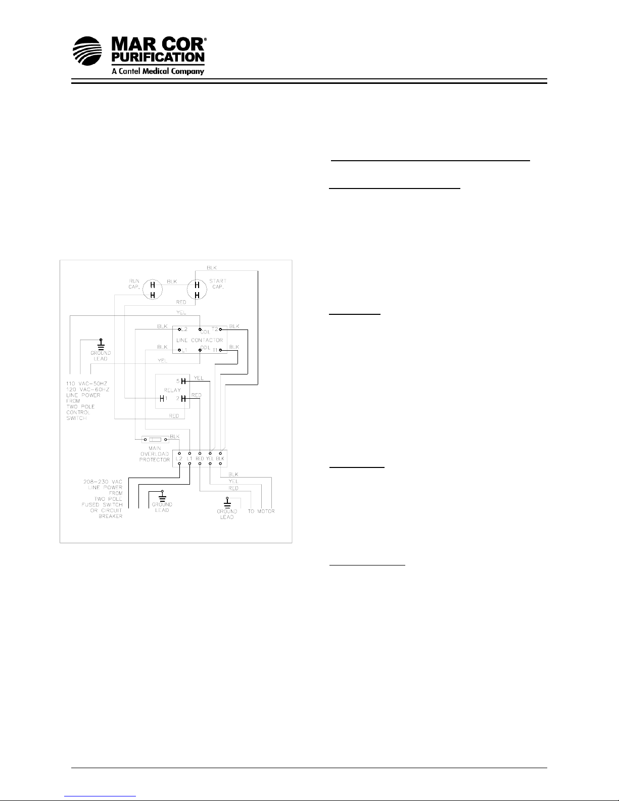
BE SURE POWER IS TURNED OFF
Checking Procedure:
A. Main Overload Protector: (Check for
continuity between the terminals.)
1. Ohmmeter Setting: R x 1.
2. Terminal Connections: Ohmmeter
B. Capacitor: (Disconnect one lead from
leads to overload terminals. Set
switch of overload to on. Meter will
read zero ohms. Set switch to off,
meter will read infinity.
each capacitor prior to checking.)
1. Ohmmeter Setting: R x 1000.
2. Terminal Connections: Individual
capacitor terminals.
3. Ohmmeter Reading: Pointer should
swing toward zero then drift back
toward infinity. No deflection means
C. Relay Coil:
D. Relay Contact
capacitor is open. Steady low
reading means it is shorted.
(Disconnect lead from terminal 5.)
1. Ohmmeter Setting: R x 1000
2. Terminal Connections: #5 and #2 on
relay.
3. Ohmmeter Reading: 5.0 / 6.7.
:
(Disconnect lead from terminal 1.)
1. Ohmmeter Setting: R x 1.
2. Terminal Connections: #1 and #2 on
relay.
3. Ohmmeter reading should be zero.
Table 2.3 Single-Phase Electrical Connections
OS1157051 Rev G 20 13-July-07
23G-Series RO System
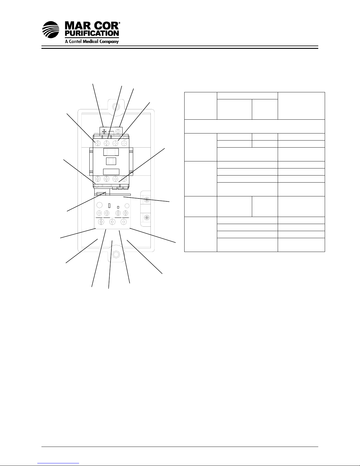
A
A
1
L2
2
Table 2.4 Three-Phase
Electrical Connections
L1
L3
Wire
Source
Note: The connections listed below apply to 23G
models with THREE PHASE motor power
T1
T3
Elect
Enclosure
Motor
Wire Color
60 Hz 50 Hz
Black Brown 96
White Blue A2
Green/yellow
Red T1
Yellow T2
Black T3
Green/yellow
14
T2
Motor
Starter
Short Red
Jumper
98
External
Power
Supply
Green/yellow
95
Short
Brown
Jumper
#1 L1
#2 L2
#3 L3
Motor
Starter/Thermal
Overload
Connection
Common
Ground
Common
Ground
A1 to 96
Common
Ground
T1
T3
96
T2
97
Figure 2.4 Three-Phase Motor Wiring
OS1157051 Rev G 21 13-July-07
 Loading...