

Marconi Instruments TF 995A/5 Operating Manual
r
OPERATING
AND
F.M.j A.M.
MAINTENANCE
HAND
BOOK
No
.
OM
995A/5
Signal Generator
TYPE TF 995A/5
(S
eriai
Nos
. JA311/001 and above)
MARCONI INSTRUMENTS LTD., ST. ALBANS, HERTS., ENGLAND
c.P.
4c
6/62jB
Copy
righl © 1961
OM
995A/S
1- 1/ 6 1
,....
Contents
...
_--_
..
__
..
Section
Page
DATA SUMMARY
4
SCHEDULE
OF
PARTS
SUPPLIED
6
l
INTRODUCTION
7
2
OPERATION
9
2.1
INSTALLATION
9
2.2
SWITCHING
ON
AND
WARMING
UP
9
2.3
OUTPUT
CONNECTJONS
9
2.4
TUNING
9
2.4.1
General Tuning
9
2.4.2
Use
of
the Crystal Calibrator
10
2.4.3
Incremental Frequency Controls ...
12
2.4.4
Interpolating Dial ...
12
2.5
SETTING
UP
FOR
C.W.
OR
MODULATED
OUTPUT
13
2.5.1 Continuous Wave ...
14
2.5.2
Amplitude Modulation
14
2.5.3
Frequency Modulation
15
2.5.4
Simultaneous F.M.
and
A.M.
17
2.6
R.F.
OUTPUT
ARRANGEMENTS
17
2.6.1
Outputs from l
fJ.V
to
100
mV
at
52
and
75
ohms
17
2.6.2
Outputs from 2
fJ.V
to
200
mV
at
75
ohms only
18
2.6.3 Outputs from
0·1
fJ.V
to
10
mV
at
52
and
75
ohms
18
2.6.4 Output in terms
of
voltage developed across externalload
19
2.6.5 Matching to externalloads other
than
52
or
75
ohms
19
2.6.6
Matching
to
balanced loads
21
2.7
SYNCHRONIZING
SIGNAL
21
3
OPERA TIONAL SUMMARY
22
4
TECHNICAL DESCRIPTION
23
4.1
R.F. CIRCUITS
23
4.2
MODULATION
SYSTEMS
24
4.3
MONITORING
ARRANGEMENTS
24
4.4
POWER
UNIT
24
S
MAINTENANCE
25
5.1
GENERAL
25
5.2
REMOV
AL
OF CASE
25
5.3
MAINS
INPUT
ARRANGEMENTS
25
5.4
ACCESS TO ENCLOSED SUB-ASSEMBLIES
26
5.4.1
R.F. Uni t
26
5.4.2
MUL
TIPLY BY
Attenuator
26
5.4.3
OUTPUT
VOLTAGE Attenuator
and
Monitor Diode
26
5.4.4
Mains Input Filter Unit
27
5.4.5
Power Unit
27
5.5
WORKING
VOLTAGES
27
5.6
REPLACEMENT
OF
VALVES
AND
SEMICONDUCTORS ...
27
5.7
PRESET
AND
SPECIALL Y SELECTED COMPONENTS
27
OM 995A/5
2
H{61
CONTENTS
Section
5.8
5.8.1
5.8.2
5.8.3
5.8.4
5.8.5
5.8.6
5.8.7
5.8.8
5.8.9
5.8.10
5.8.11
5.8.12
5.8.13
5.8.14
5.8.15
5.8.16
5.8.17
6
7
8
SCHEDULE OF TESTS
Apparatus Required
Insulation
Hum
Level
Crystal Oscillator
Bask Oscillator
Frequency Multipliers
1,5-
to l3-5-Mc/s Band
R.F. Output Voltage Accuracy
Modulation Oscillator
Reactance
Valve Input Potentiometer
Frequency Modulation
Incremental Frequency
High Deviation
ExternaI
F.M.-Metering
Accuracy
Internai A.M.
Externai A.M.
Spurious F.M. on C.W.
COMPONENT LAYOUT ILLUSTRATIONS
GENERAL UNDERSIDE VIEW
FROM
REAR (CASE REMOVED)
L.F.
AND
R.F. UNITS (TOP VIEW)
R.F. UNIT (GENERAL UNDERSIDE VIEW) ...
R.F. UNIT (CLOSE-UP
OF
PORTION
OF
UNDERSIDE)
L.F. UNIT (UNDERSIDE VIEW) ...
ATTENUATORS (COVERS REMOVED)
POWER
UNIT
SPARES ORDERING SCHEDULE
CIRCUIT DIAGRAMS
R.F. and L.F. Units
Power Unit
DEcmEL
CONVERSION TABLES
Page
30
30
30
30
30
30
30
31
31
31
32
32
32
33
33
33
33
33
Fig.6.1
Fig.6.2
Fig.6.3
Fig.6.4
Fig.6.5
Fig.6.6
Fig.6.7
SOS
l
Fig.
8.1
Fig.8.2
OM
99SA/S
3
1-1/61
I
1/61
Data
Summary
Frequency
RA;\GE:
CALIBRATIO"S
ACCLRACY:
STABILITY
:
FINE
Tl'NING
CONTROL:
l NCREME"STA 1
COl>:TROL:
Output
\OLTA(if:
HIGH
Ol'TPCTS:
LO\\'
OI'TPl"TS:
ACfURACY:
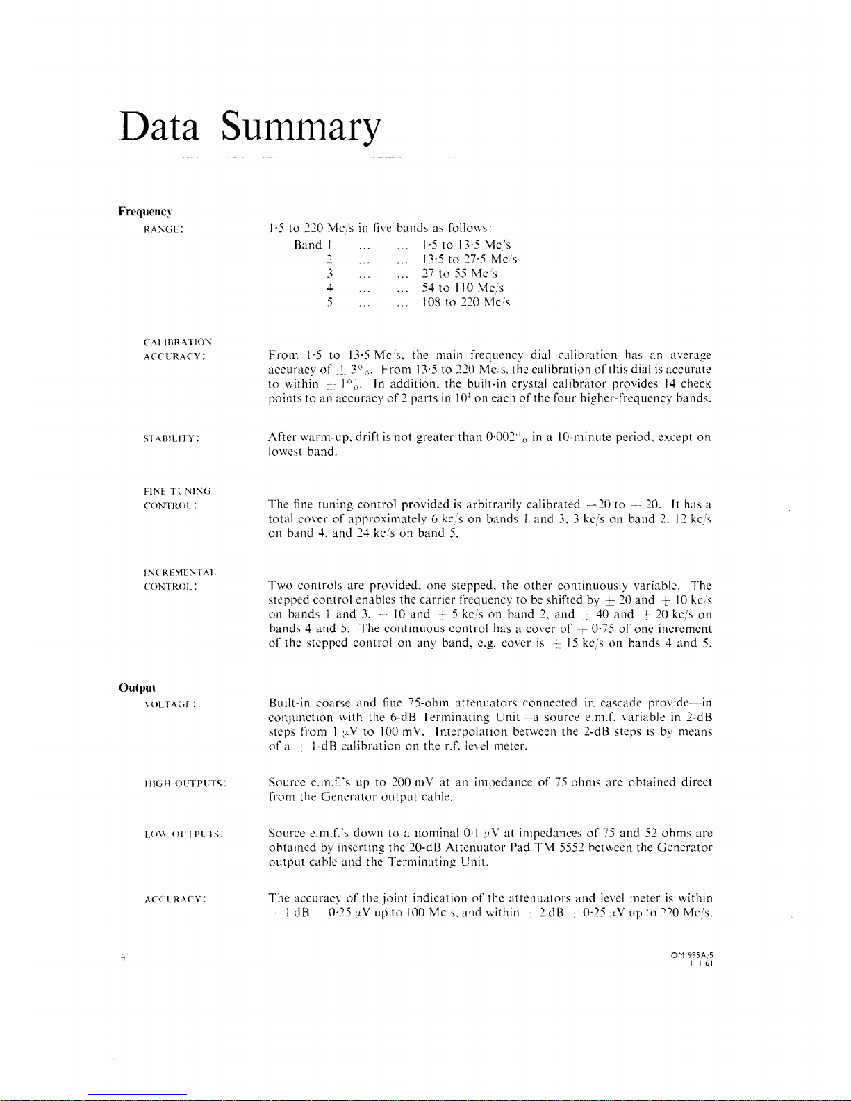
]'5
to
220 MCis in five
bands
as follows:
Band
l
1·5
to
13·5
Mc's
2 13·5 to 27·5
Mc's
3
27
to
55
Mc:s
4
54tollOMcs
5
108 to
220Mc/s
From
1·5
to
13·5
Mc/s,
the main frequency dial
calibration
has
un
average
accuracyof
3°
(l.
From
13·5
to
220 MCis. the
calibration
of
this dia l
is
accuratc
to
within l
o.
In
addition,
the built-in crystal
calibrator
provides
14
check
points
to
an
accuraey
of 2 parts
in J
O~
on
each
of
the
four
higher-frequency bands.
Af
ter \Varm-up. drift is
not
greater
than
0·002" o in a 10-minute period. except
on
lowes! band.
The
fine
tuning
control provided is arbitrarily
calibrated
-20
to
20. It has a
total cO\er
of
approximateJy 6 kc's
on
bands J and
3.
3 kcis
on
band
2,
12
kels
on
band
4.
and
24
kcs
on
band
5.
Two
controls
are provided,
one
stepped, the
other
continuously
variable.
The
stepped controI enables
the
carrier frequency
to
be shifted by 20
and,
10 kc!:,;
on
bands I
and
3,
lO
and
5 kels
on
band
2,
and
--'-
40
and
20 kc/s
on
bands 4
and
5.
The
eominuous
controI has a eover
of,
0·75
of
one
increment
of
the
stepped controi
on
any
band,
e.g. eover
is
15
on
bands 4
and
5.
Built-in coarse
and
line 75-ohm
attenuators
conneeted
in
caseade
provide~in
conjunetion
with the 6-dB
Terminating
Unit--a
source e.m.f.
\ariable
in 2-dB
steps
from]
:J.V
to
100mV.
Interpolation
between
the
2-dB steps
is
by means
of a -'-.
I-dB
calibration
on
the r.f. level meter.
Source
e.m.f:s
up
to
200
mV
at
an
impedance
of
75
ohms
are
obtained
direct
from
the
Generator
output
cable.
SOUl'ce
e.m.f.\
down
to a nominal
0,(
:J.V
at
impedances
of
75
and
52
ohms
are
obtained
by inserting
the
20-dB
Attenuator
Pad
TM
5552 between the
Generator
output
cable
and
the
Terminating
Uni!.
The
accuraey
of
the
joint
indication
of
the
mtenualors
and
leve! meter
is
within
] dB
--:
0·25
:LV
up
to
100
Mes.
and
within 2 dB 0·25
:LV
up
to
220 Mc/s.
OM
995A;5
1 1
"61
-4
DATA
SUivHv1ARY
Modulation
FREQUENCY
MODULATIO:--;
:
SPURJOl!S
LM.
ON
C.W.:
AMPLITUDE
MOD
l;LA TIOl'.' :
A.M.DEPTH
INDICATION
:
SYKCHRONIZING
SIGNAL:
Power Supply:
Dimensions
and
Weight:
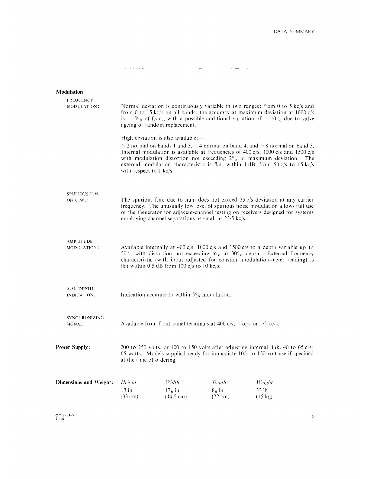
Normal
deviation
is
eontinuously
variable
in
two
ranges:
from O to
5 kels
and
from O to
15
ke, s
on
all
bands;
the
aeeuraey
at
maxim
um
deviation
at
1000
e/s
is
-1-
5°
()
of
f.s.d"
with
a possible
additional
variation
of
==
10° o
due
to
valve
ageing
or
random
replacement.
High
deviation
is
also
available:-
'. 2
normal
on
bands I and
3. >.4
normal
on
band
4.
and
x S
normal
on
band
5.
InternaI
modulation
is
available
at
frequeneies
of
400 e/s, 1000 e/s
and
1500 e/s
with
modulation
distortion
not
exeeeding
2° o
at
maximum
deviation.
The
externaI modulation
eharaeteristie
is
flat.
within 1 dB.
from
50 e/s
to
15
kels
with
respeet
to
I kels.
The
spurious
f.
m.
due
to
hum
does
not
exeeed 25 e/s
deviation
at
any
carrie
r
frequeney.
The
unusually
low
level
of
spurious
noise
modulation
allows
full use
of
the
Generator
for
adjaeent-ehannel
testing
on
receivers
designed
for
systems
employing
ehannel
separations
as
small
as
22·5 kels.
Available
internally
at
400 e/s, 1000 eis
and
1500 e/s
to a deptll
variable
up
to
6
0
50°
()
with
distortion
not
exeeeding
() at 30°
(j
depth.
ExternaI
frequeney
eharaeteristie
(with
input
adjusted
for
constant
modulation-meter
reading)
is
Aat
within O'5
dB
from
100 e,s
to
10
ke,
s.
I
ndieation
aeeurate
to
within
5~
~
modulation.
Available
from
front-panel
terminals
at
400 e/s. 1 ke,'s
or
1·5
keso
200
to
250 volts.
or
100
to
J 50
volts
after
adjusting
internaI
lin k. 40
to
65
e/s;
65
watts.
Models
supplied
ready
for
immediate
100-
to
150-volt use
if
speeiticd
at
the
t ime
of
ordering.
Height
~Vidth
Depth Weight
13
in
17~
in
Stin
33
Ib
(33
cm)
(44,5
cm)
(22
cm)
(15 kg)
OM
995A,5
Hj61
5
Schedule
of
Parts
Supplied
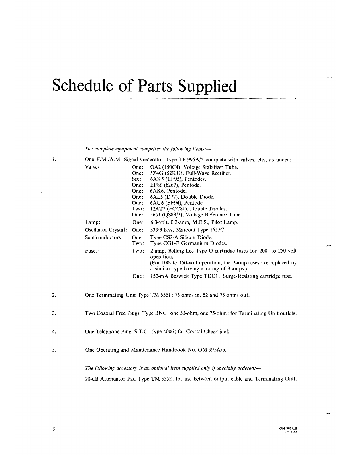
The complete equipment comprises thefollowing items.
I.
One F.M./A.M. Signal Generator Type
TF
995A/5 complete with valves, etc., as
under:~
Valves: One: OA2 (l50C4), Voltage Stabilizer Tube.
One: 5Z4G (52KU), Full-Wave Rectifier.
Six: 6AK5 (EF95), Pentodes.
One: EF86 (6267), Pentode.
One: 6AK6, Pentode.
One: 6AL5 (D71), Double Diode.
One: 6AU6 (EF94), Pentode.
Two:
12AT7
(ECC8I), Double Triodes.
One:
5651
(QS83/3), Voltage Reference Tube.
Lamp:
One:
6'3-volt, 0'3-amp, M.E.S., Pilot Lamp.
Oscillator Crystal: One:
333·3
kels, Marconi Type 1655C.
Semiconductors: One:
Type CS2-A Silicon Diode.
Two:
Type
CGI-E
Germanium Diodes.
Fuses:
Two: 2-amp, Belling-Lee Type
O cartridge fuses for 200- to 250-volt
operation.
(For
100-
to I 50-volt operation, the 2-amp fuses are replaced
by
a similar type having a rating
of
3 amps.)
One: I50-mA Beswick Type
TDCll
Surge-Resisting cartridge fuse.
2.
One Terminating Unit Type TM 5551;
75
ohms in,
52
and
75
ohms out.
3.
Two Coaxial Free Plugs, Type BNC; one 50-ohm, one 75-ohm; for Terminating Unit outlets.
4.
One Telephone Plug, S.T.C. Type 4006; for Crystal Check jack.
5.
One Operating and Maintenance Handbook No.
OM
995A/5.
The following accessory is an optional item supplied only ifspecially
ordered:-
20-dB Attenuator Pad Type TM 5552; for
use
between output cable and Terminating Unit.
OH
995A/5
1*-6/62
6
1
Introduction
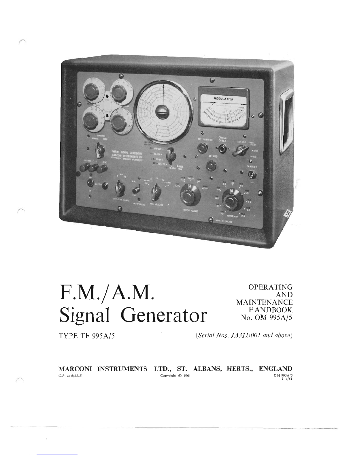
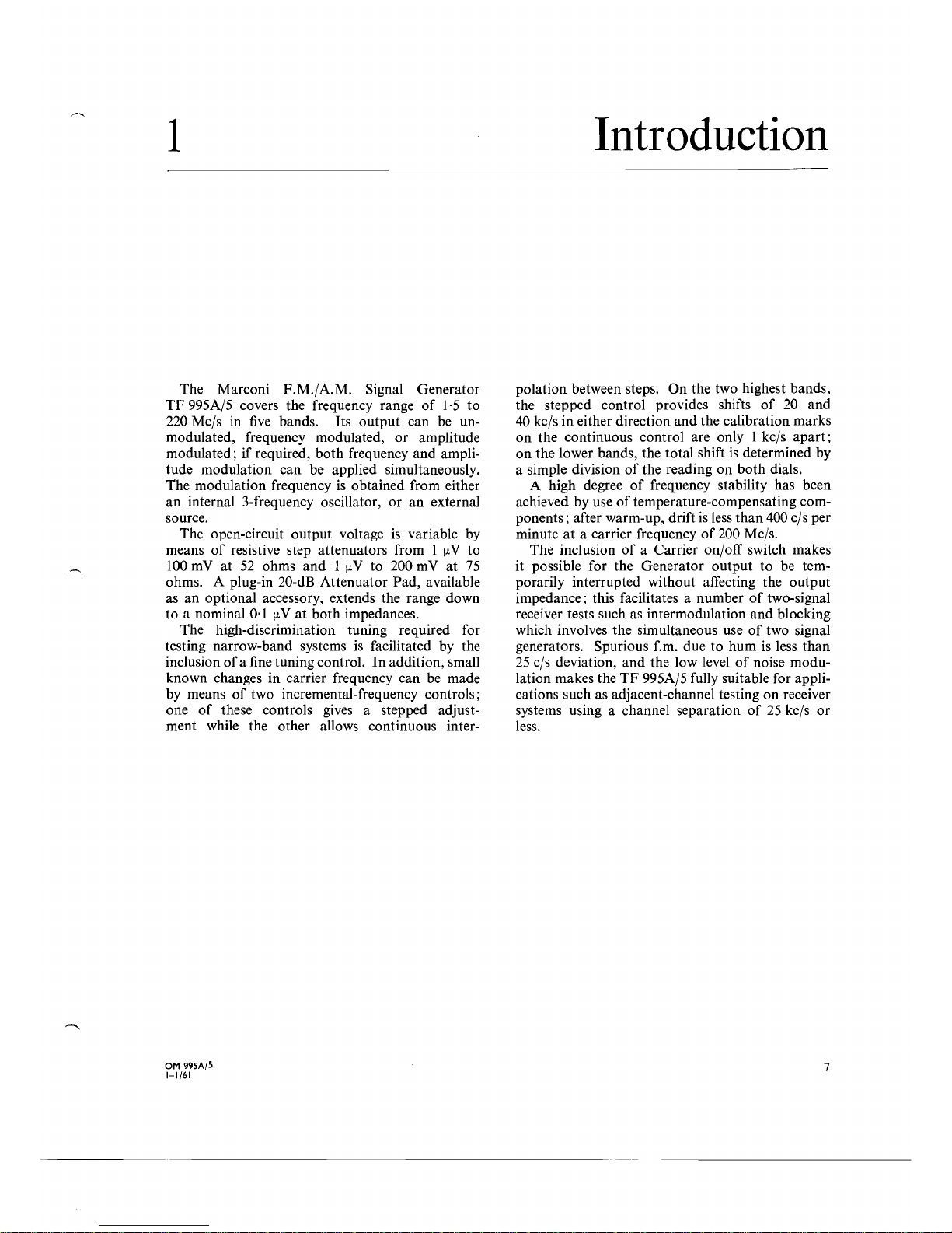
The Marconi F.M./A.M. Signal Generator
TF
995A/5 covers the frequency range
of
1·5
to
220 Mc/s in
five
bands. Its output can be un-
modulated, frequency modulated,
or
amplitude
modulated;
if
required,
both
frequency and amplitude modulation can be applied simultaneously.
The modulation frequency
is
obtained from either
an
internai 3-frequency oscillator,
or
an
externai
source.
The open-circuit output voltage
is
variable by
means
of
resistive step attenuators from 1
Il.
V to
100
mV
at
52
ohms
and 1 Il.V
to 200
mV
at
75
ohms. A plug-in 20-dB Attenuator Pad, available
as
an
optional accessory, extends the range down
to a nominal
0·1
Il.V at
both
impedances.
The high-discrimination tuning required for
testing narrow-band systems
is
facilitated by the
inclusion
of a fine
tuning controI.
In
addition, small
known changes in carrier frequency can be made
by means
of
two incremental-frequency controis;
one
of
these controis gives a stepped adjust-
ment while the other allows continuous inter-
polation between steps. On the two highest bands,
the stepped controi provides shifts
of
20
and
40
kc/s
in
either direction and the calibration marks
on
the continuous controi are only 1 kc/s apart;
on
the lower bands, the total shift
is
determined by
a simple division
of
the reading
on
both
diais.
A high degree
of
frequency stability has been
achieved by use
of
temperature-compensating com-
ponents; after warm-up, drift
is
less
than
400 c/s per
minute
at
a carrier frequency
of
200 Mc/s.
The inclusion
of
a Carrier on/off switch makes
it possible for the Generator output to be temporarily interrupted without affecting the output
impedance; this facilitates a number
of
two-signal
receiver tests such as intermodulation and blocking
which involves the simultaneous use
of
two signal
generators. Spurious f.m. due to hum
is
less than
25
c/s deviation, and the low level
of
noise modu-
lation makes the
TF
995A/5 fully suitable for appli-
cations such as adjacent-channel testing
on
receiver
systems using a channel separation
of
25
kc/s
or
less.
OM 995A/5
7
1-1/61

II
6
5
Il
13
4
===~-14
3
15
2
19
18
17
16
I.
Pilot
Lamp
and
10.
Meter
indicates
carrier
level, f.m.
deviation,
or
a.m.
Mains
Supply
Switch
depth
depending
on
setting
of
Meter
Reads switch
2.
External
Modulation
Input
for
f.m.
or
a.m. and
II.
Crystal
Check
Jack
Sync
Output
from
internai
modulation
oscillator
Plug
in
headphones
here
to
switch
on crystal
check
oscillator
3.
Normal:
deviation
is
as
shown
on
meter
High:
multiply
meter
reading
by
factor
on
Range
switch
12.
Case
Handle
Recess
stowage
for mains supply plug
13.
Modulation
Frequency
Selector
4.
Coarse
Tuning
Controi
Choice
of 3
frequencies
from
internai
oscillator
5.
Incremental
Frequency
Controls
14.
Set
Mod
Controi
Carrier
shift
is
given
by
dial readings multiplied
by
factor
Adjusts f.m.
deviation
or
a.m.
depth
on
Range
switch
15.
Interrupts
Output
without
switching
off filaments
6.
Fine
Tuning
Controi
16.
Output
Attenuators
7.
Range
Selector
Direct
reading
in
source
e.m.f.
at
output
of
Terminating
8.
Main
Tuning
Dial
Unit
when
carrier
is
adjusted
to
Set
R.F.
mark
on
meter
Knurled boss adjusts
cursor
to
standardize
scale against
17.
Modulation
Selector
crystal check
points
18.
Meter
Function
Selector
9.
Set
Carrier Controi
For adjusting
unmodulated
carrier
to
Set
R.F.
mark
on
19.
Deviation
Range
Selector
meter
Read deviation
from
corresponding
scale on
meter
Fig.2.1
Contro/s.
OM 995A/S
1-1 /
61
8
2
2.1
INSTALLATION
Uniess otherwise specified, the Signal
Generator
is
dispatched
wi
th i
ts
valves i n posi tion and
wi
th i
ts
mains input circuit adjusted for immediate use with
a 240-volt, 40- to 65-c/s mains supply. The instrument
can
be adjusted for
operation
from any other
40-
to 65-c/s supply voltage in the ranges 200 to 250
and
100
to
150
volts.
To
check
or
alter the settings
of
the mains transformer tappings, refer to
MAINTENANCE,
Section 5.3.
2.2
SWITCHING
ON
AND
WARMING
UP
Before switching on, be guite sure that the instru-
ment
is
correctly adjusted
to
suit the particular
mains supply to which it
is
to
be
connected. Then
proceed as
fo11ows:-
(J) Connect the mains
lead-stowed
in the left-
hand
case-handle
recess-to
the mains supply
socket.
(2)
Switch
ON
by
means
of
the
SUPPLY
switch; the
red pilot lamp should now glow.
(3)
Bcfore proceeding further,
allowashort
time
- say
f1ve
minutes-to
elapse for the internai
circuits to warm up.
If
a particularJy high
standard
of
freguency stability
is
required, this
time should
be
increased
to
about
60
minutes.
2.3
OUTPUT
CONNECTIONS
The
r.f.
output
from the Signal Generator
is
derived,
at
a source impedance
of
75
ohms, via a
permanently attached coaxial lead f1tted with a
BNC
free socket; the lead is stowed in the right-
hand case-handle recess.
The
TERMINATING
UNIT,
which will normally be
plugged on to the
output
lead, has two outlets, one
of
75
ohms impedance and the other
of
52
ohms.
Two free plugs are supplied for making connection
to the
TERMINATING
UNIT
outlets.
The 20-dB
ATTENUATOR
PAD,
available as
an
optional
accessory,
can
be
inserted between the
Generator
output
socket and the
TERMINATJNG
UNIT
input plug when low outputs are required.
Details
on
the use
of
the
TERMINATING
UNIT
and
ATTENUATOR
PAD
are given in Section 2.6,
R.F.
OUTPUT
ARRANGEMENTS.
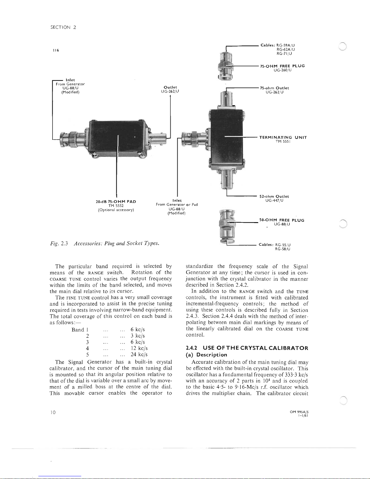
Equivalents to the free plugs supplied,
and
illus-
trated in Fig. 2.3, are as
follows:-
OM
99SA/S
1-
1/61
Operation
75
ohm
50
ohm
Great Britain,
Air
Ministry:
10H/20946 lOH/20935
Films and
Equipment:
UG-260/U
UG-88/U
Transradio
Ltd.:
BN.
1/7
BN. 1/5
Belling and Lee:
L.
1331/FP
United States,
Military
No.:
UG-260/ U
UG-88/U
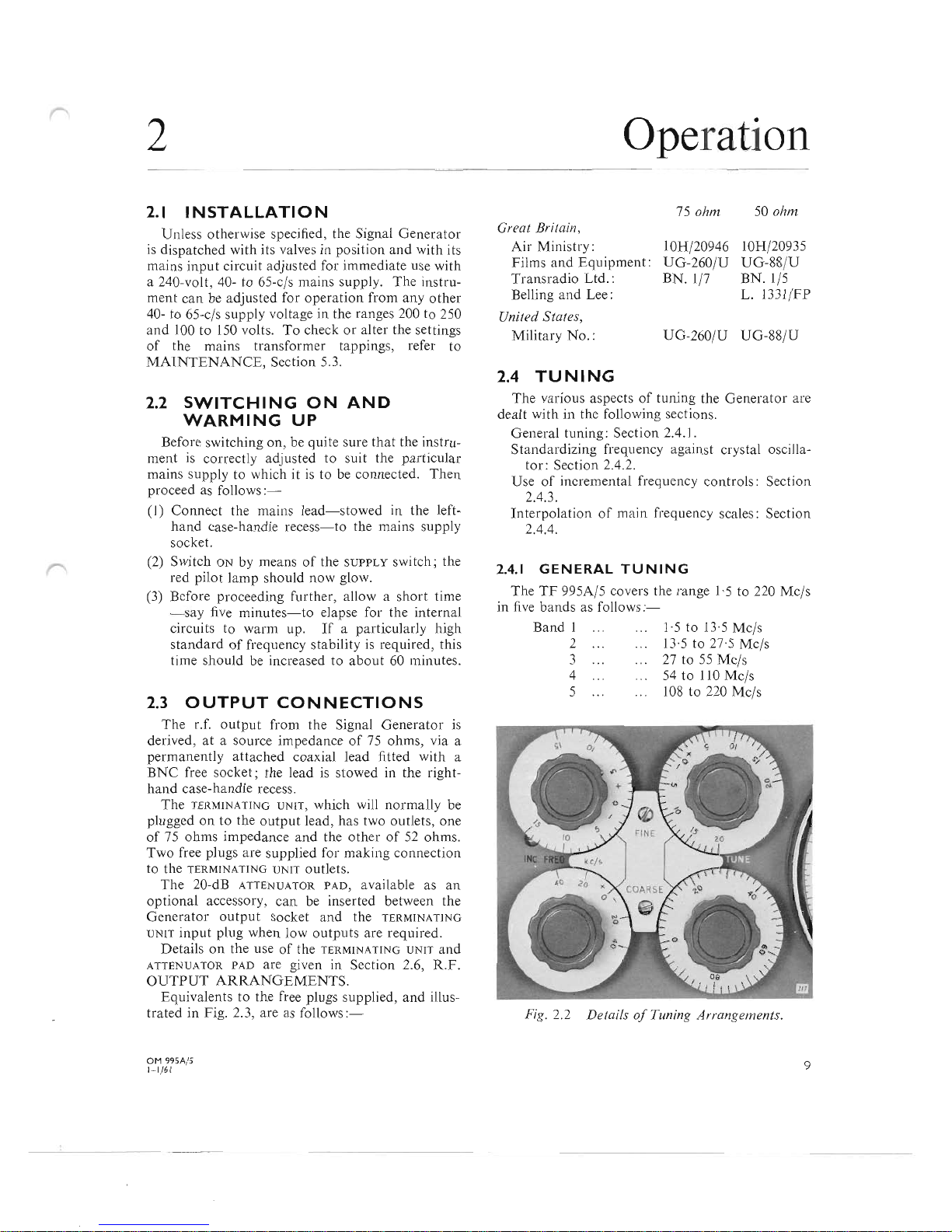
2.4
TUNING
The various aspects
of
tuning the Generator are
dealt with in the following sections.
General tuning : Section 2.4.1.
Standardizing frequency against crystal oscilla-
tor: Section 2.4.2.
Use
of
incremental freguency controis: Section
2.4.3.
Interpolation
of
main freguency scales : Section
2.4.4.
2.4.1
GENERAL
TUNING
The
TF
995A/5 covers the range
1·5
to 220 Mc/s
in
f1ve
bands as
follows:-
Band l
1·5 to
13-5 Mc/s
2
13-5
to 27·5 Mc/s
3
27 to
55 Mc/s
4
54
to
110
Mc/s
5
108
to
220 Mc/s
Fig. 2.2 Details
of
Tuning Arrangements.
9
SECTION 2
_-----
Cables:
RG-59A/U
116
RG-62AjU
RG-11/U
~
r----75-0HM
FREE
PLUG
UG-260jU
Inlet
From
Generator
UG-88jU
(Modined)
Outlet
UG-262
jU
,..------75-ohm
Outlet
UG-262
jU
TERMINATING
UNIT
TM
5551
L--
____
52-ohm
Outlet
Inlet
UG-441
jU
TM
5552
20-dB
75-0HM
PAD
From
Generator
or
Pad
(Option
al
accessory)
UG-88
IU
(Modined)
Fig.
2.3 Accessories: Plug and Socket Types.
The
particular
band
required
is seleeted by
means
of
the
RANGE
switch.
Rotation
of
the
COARSE
TUNE
controI
varies
the
output
frequency
withjn the limits
of
the
band
seleeted,
and
moves
the
main
dial
relative to its cursor.
The
fiNE
TUNE
controi
has
a very small coverage
and
is
incorporated
to
assist
in
the precise
tuning
required
in
tests involving
narrow-band
equipment.
The
total coverage
of
this
controlon
each
band
is
as follows :-
Band
l 6 kels
2
3
ke
ls
3
6
kels
4
12
kels
5
24
ke
ls
The
Signal
Generator
has
a built-in crystal
calibrator, and
the
cursor
of
the
main
tuning
dial
is
mounted
so
that
its
angular
position
relative to
that
of
the dial is variable over a small
are
by
move-
ment
of
a milled boss
at
the centre
of
the
dia\.
This
movable
cursor
enables the
operator
to
'__""","
___
50.0HM
FREE
PLUG
UG
·88!U
L--
____
Cables:
RG·5S
:U
RG ·S8
jU
standardize
the frequency scale
of
the Signal
Generator
at
any
time;
the
cursor
is used
in
con-
junction
with
the
crystal
calibrator
in
the
malmer
described
in
Section 2.4.2.
In
addition
to the
RANGE
switch
and
the
TUNE
controls,
the
instrument
is fitted
with
calibrated
incremental-frequency
controIs
; the
method
of
using these
controls
is described fully
in
Section
2.4.3.
Section
2.4.4 deals
with
the
method
of
inter-
poJating
between
main
dial
marking
s by
means
of
the jinearly
calibrated
dialon
the
COARSE
TUNE
control.
2.4.2
USE
OF
THE
CRYSTAL
CALlBRATOR
(a)
Description
Accurate
calibration
of
the
main
tuning
dial
may
be effected
with
the built-in crystal osciUator. This
oscillator
has a fundamental
frequency
of
333·3 kels
with
an
accuracy
of 2 parts
in 104 and
is
coupled
to the basic 4·5- to 9·16-Mc/s r.f.
oscillator
which
drives the multiplier chain.
The
calibrator
circuit
OM
995A/ S
10
1- 1/
61
is
automatkally brought into
use
when a pair
of
high-resistance headphones are plugged into the
CRYSTAL CHECK jack socket; with the aid
of
the
headphones, the difference frequency between
the basic oscillator and the harmonic multiples
of
the calibrator's
333·
3 kc/s can be monitored aurally.
Because the outputs on the four higher-frequency
bands are all derived directly from the multiplier
chain, their frequencies have an exact integral
relationship to the frequency
of
the basic oscillator.
It
follows, therefore, that setting the COARSE TUNE
controi to bring the basic-oscillator frequency to
that
of
a crystal harmonic will also bring the fre-
quency
of
the outputs from the multiplier chain to
a known relationship with the crystal harmonic,
and allow the frequency dial
to
be standardized
with a high degree
of
accuracy.
Outputs on the lowest-frequency band are not
derived directly from the multiplier chain; their
generation involves a heterodyne action between
the
27-
to 55-Mc/s multiplier and a 30-Mc/s fixed
oscillator which
is
not locked to the basic oscillator.
For
this reason, although use
is
made
of
the crystal
calibrator when setting up for
1,5-
to 13'5-Mc/s
outputs, the accuracy
of
standardization
is
of
a
lower order than
that
obtained
on
the four higher-
frequency bands.
(b) Check-Point Frequencies
The calibrator provides a total
of
56
check pOlnts
between
13·5
and 220 Mc/s; these occur as
follows:-
Band
2,
13·5
to 27·5 Mc/s:
at
all multiples
of
l Mc/s from
14
to
27
Mc/s inclusive.
Band
3,
27
to
55
Mc/s:
at
all multiples
of
2 Mc/s
from
28
to
54
Mc/s inclusive.
Band
4,
54
to
110
Mc/s: at all multiples
of
4 Mc/s
from
56
to
108
Mc/s inclusive.
Band
5,
108
to
220
Mc/s: at all multiples
of
8 Mc/s from
112
to
216
Mc/s
inc1usive.
(c) Standardization Procedure
As shown above, the calibrator allows the fre-
quency scale
to
be
checked at
14
different points
on each
of
the above bands, and the adjustable
cursor can
be
set
to
correspond exactly with any
one
of
these points.
When the Signal Generator
is
to
be
used above
13·5
Mc/s
to
provide
an
output at a single spot
frequency,
or
over a narrow band
of
frequencies,
the cursor should
be
set up at the nearest crystal
check point.
When the Signal Generator
is
to
be
used over a
wide range
of
frequencies, and it
is
inconvenient to
OM 99SA/S
SECTION
2
reset the cursor for each material frequency change,
or, altematively, when using the 1·5· to 13'5-Mc/s
band, the procedure
is
varied to reduce the mean
error to a minimum. The method
of
standardizing
the frequency scale for subsequent general use
is
as
follows:-
(l)
Set the INC. FREQ. controis to zero and the FINE
TUNE
controI to mid-position.
(2)
Set the RANGE switch to 13'5-27 Mc/s.
(3)
Using the headphones plugged into the CRYSTAL
CHECK
jack, tune the main dial to a crystal
check point near the centre
of
the band; e.g.
20
Mc/s.
When using the calibrator, the
MOD. SELECTOR
must
be
set to a position other than INT.
MOD.-
F.M.
or
EXT.
MOD.-F.M.
This ensures that the
variable oscillator
is
not being frequency modulated
-a
condition which prevents precise setting
of
the
COARSE TUNE controi for the lowest-frequency beat
note in the headphones, since it gives rise to a
fluctuating tone.
After using the calibrator, the Signal Generator
can,
of
course, be set up for f.m. without invali-
dating this frequency standardization.
(4)
Adjust the milled boss in the centre
of
the dial
to bring the cursor exactly in line with the
calibration mark corresponding to the crystal
check point.
If
the Signal Generator has been out
of
use for
some time,
it
may be necessary to use a coin in the
slot provided in order
to
rotate the milled boss.
(5)
Check the calibration accuracy at several crystal
check points both above and below the check
point at which the cursor was set in
(4)
above.
(6) Readjust the cursor setting to equalize the errors
over the band; e.g. it might be found that, with
the frequency scale indication correct at
20
Mc/s, the indication was high
at
both
15
and
25
Mc/s-in
such a case, the errors would
be
equalized by making the indication a little low
at
20
Mc/s, and thus not
so
high at
15
and
25
Mc/s.
It
will
be noted that, in the above procedure, the
frequency scale
is
standardized on the 13'5- to
27-Mc/s band. This band
is
specified since its
corresponding scale calibrations occupy the longest
arc on the dial. The dial can therefore
be
read with
a high degree
of
diserimination on this band and
the correct cursor setting most easily determined.
Once the frequency scale has been standardized
on
the
13·5-
to 27-Mc/s band, the cursor
is
correctIy
set to give the minimum mean error on the other
three direct-multiple bands.
It
is
also correctly set
for the
1,5-
to 13'5-Mc/s band.
11
1-1/61
SlCIIUN
2
When
~tandardizcd
in
this way, the
l1lain
tuning
dial indication for frequencies above
13·5
Mes
is
accurate to at least I"
n,
and
will
generally
be
with-
in
0'5",,: for frequencies below 13'5 Mc/s. the
average eITor doc
s not exceed :
JO
'f'
2.4.3
INCREMENTAl
FREQUENCY
CONTROlS
These eontmls are weil suited to perforl1ling
bandwidth
or
sil1lilar measurel1lents since they are
a convenient l1leans
of
producing small. accurately-
known changes in carrie
r frequency. They are not
connccted directly to the
rJ. oscillator either
l1lechanicallyor electrically, but operate
by
varying
the d.c. potential at the grid
of
the reactor valve
so that they are completely free from backlash
of
any kind.
To utilize these controis. proceed as follows
(I)
With the
J;\C,
FREQ. comrols set to their centre-
zem position. tune the Signal Generator to the
required centre-frequency
by
l1leans
of
the
RA'JGE
switch and the
lT;\E
controis.
(2) Rotate the
INC.
FREQ. controis to produce the
required shift
or
the required change in response
depending
on
the l1lethod
of
l11eaSUrel1lenl.
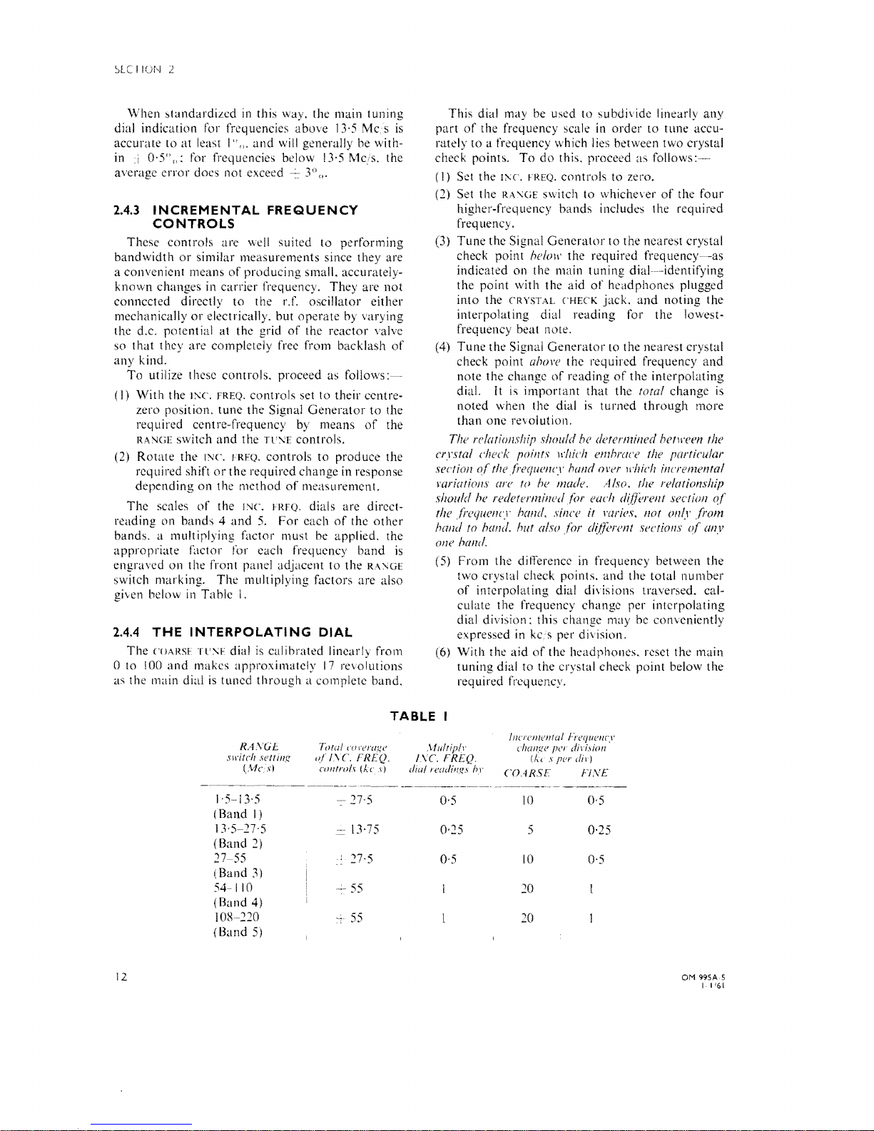
The scales
of
the 1'JC. FRFQ. dials are direct-
reading on bands 4
and
5.
For each
of
the
other
bands. a multiplying factor must
be
applied. the
appropriate factor for each frequency band
is
engraved on the front panel adjacent to the
RA;\GE
switch marking. The multiplying factors are also
given below
in
Table l.
2.4.4
THE
INTERPOLATING
DIAl
The
COARSf
"IT:--;f dial
is
calibrated linearly from
O to
100
and
makes approximately
17
revolutions
as the main dial
is
tuned through a complete band.
This dial may
be
used to subdivide linearly any
part
of
the frequency scale
in
order to tune accu-
rately to a frequency \vhich lies between two crystal
check point5. To
do
this. proceed as
follows:-
(]) Set the
1;\(',
FREQ. controis to zero.
(2) Set the
RA;\GE
switch to whichever
of
the four
higher-frequency bands indudes the required
frequency.
(3) Tune the Signal Generator to the nearest crystal
check point
helOlI' the required
frequency-as
indicated on the
111ain
tuning dial----identifying
the point with the aid
of
headphones plugged
into the
CRYSTAL
CHECK
jack.
and
noting the
interpo]ating dia
I reading for the lowest-
frequency beat note.
(4) Tune the Signal
Generator
to
the neares! crystal
check point
ahol'e the required frequency
and
note the change
of
reading
of
the interpolating
dia!.
lt
is
important that the foral change
is
noted when the dia I
is
turned through more
than one revolution.
The
re/ariollship
s/muld hl'
defermilled
befll'een the
crrsta/
check poil/t.\'
lI'!IiCI!
emhrace the partieular
sectian
of
thefrequel1cy
hand
OI'er lI'hich incrementa/
rariatiolls are
to
he
made. A/so. the re/arionship
sllOlI/d he redetermil/ed
for
each differel/t sectiol/
of
the frequency hall
d,
since
ir
mries.
Ilar
011/.1'
from
hand
to halld, hut a/so
for
dijferent seetiolIs
of
(lilY
olle hand.
(5) From the ditTerence
in
frequency between the
two crystal check points. and the total number
of
interpolating dial di\isions traversed. calculate the frequency change per interpolating
dial division: this change may
be
conveniently
expressed
in
kc.s per division.
(6) With the aid
of
the headphones, reset the main
tuning dial to the crystal check point below the
req u i red freq uency.
RAXGE
slI'irch sert illg
C\cfci.\l
1,5"-13,5
(Band l)
13,5-27,5
(Band
2)
27-55
(Band
3)
54-110
(Band 4)
10/1-210
(Band 5)
TABLE
Towl
('orerage
0/
ISe.
FREQ.
.\fll/lip'"
I.\C
FREQ.
colIIrois
(AC
.1)
dial
readillgs
1'.1'
n·5
0·5
- 13·75
0·25
27·5
0·5
55
,-
55
IlI('I'clI7el1lal "i'cC/ucl/cy
('hallge
per
dil'isio/l
(kc s per
dir)
COARSE
Fl
,VE
10
0·5
5
0·25
10
0'5
20
20
OM
99SAS
1-1'61
12
(7)
Rotate
the COARSE TC:--;E
controI
so
that
the
interpolating
dia! traverses the
correct
number
of
divisions to give the required frequency.
It
is
recommended
that
the
required
frequency
should
always be
approachcd
from
the
low-
frequency side in
order
to
eliminate
all possibility
of
error
due
to
backlash.
The
following
example
illustrates
the
use
of
thc
interpolating
diaI to
obtain
an
output
from
the
instrument
at
an
accurate
frequency
of
74·25
Mcs.
Example:
With
the
lLNE
controI
set
to
the crystal
check point
at
72 Mc/s. the
interpolating
dial read-
was
17.
With
the
TlJ'\E
controi
set
to
the crystal
check
point
of
76
Mc/s
the new
reading
on
the
auxiliary
dia
l was 40.
The
total
number
of
inter-
polating
dial divisions traversed was I
n.
the
dia!
having
rotated
through
51ightly
more
than
one
revolution
for
the
frequency
change
of 4 Mcs.
i.e.
4,000 kcjs. In
thi~
case. a
change
of
1 division
on
the
interpolaling
dial
corresponded.
he/lreen
T2
and
76
Mc/s,
to a nominal
frequency
change
of
4.000
32·5 kc.'s.
In
Therefore,
by
starting
from
the
original
auxiliary
dial
setting
at
72
Mcis
(72.000
kcs)
the
rcquired
frequency
of
74·25 Me!s (74.250
ke
s)
was
obtained
by
rotating
the
auxiliary
dial
through
74,250 72.000 2.250 69 divisions.
32·5 32·5
Since it will be
appreciated
t hat only
typieal
figures
eould
be
quoted
above.
il
folIow:,
that
the
relation5hip between frequency
change
and
change
',E(lION
2
in
inlerpolating
dial setting
should
be
determined
-in
the
manner
outlined
above
~for
the
particular
TF
995A5
in
use.
2.S
SETTING
UP
FOR
C.W.
OR
MODULATED
OUTPUT
The
Signal
Generator
will
gi\c
the
following
types
of
r.f.
outPUI:-
(I)
Continuous
wa\e
(see Seelion 2.5.1
l.
(l)
Amplilude
modulated
(see
Seclion
2.5.2).
\ari-
able
to
50""
depth.
(a)
from
the
internai a.f.
oscillator
at
400.
1.000,
or
1,500
C,S,
(b)
from
an externai sinewa\'e
SOLlrce.
within
the range 100 e/s
lo
lO
kc,'s.
(3)
Frequency
modulated
(see
Section
~.5.3).
vari-
able
10
maximum
frequency
de\ialions
ranging
from
15
kc's to 120
kes,
(a)
from
the internaI a.f.
oscillator
at
400.
1.000.
or
1.500
cs.
(bl
from
an
externai
sinewave source. within
thc
range 50 C,S lo
15
kc
s.
(4)
Simultaneous
frequency
and
amplilude
modu-
lation
(see Sect ion 2,5.4);
the
amplitude
modula-
tion
being
obtained
from the internaI a.f.
oscillator.
and
the frequency
modulation
from
an external
source
as (3) (b), above.
When
setting
up for
amplitude
or
frequcncy
modulation
as described
in
Sections 2.5.2
and
2.5.3,
il
may
be
obsened
that.
with the METER READS key
held
to
either A.M.
or
F.\1. as applics. the
apparent
modulation
as measured on
externa I apparatus
is
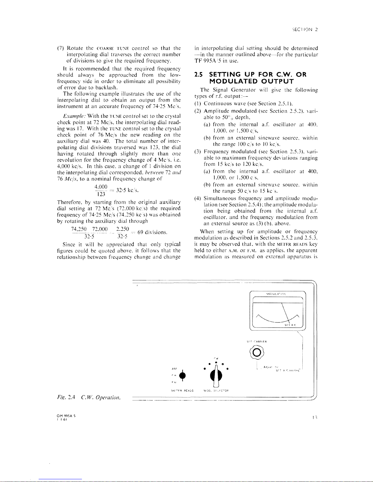
@
Fig.
2.4
C.
W. Operation.
OM 995A S
I i
! 161
SECTlON 2
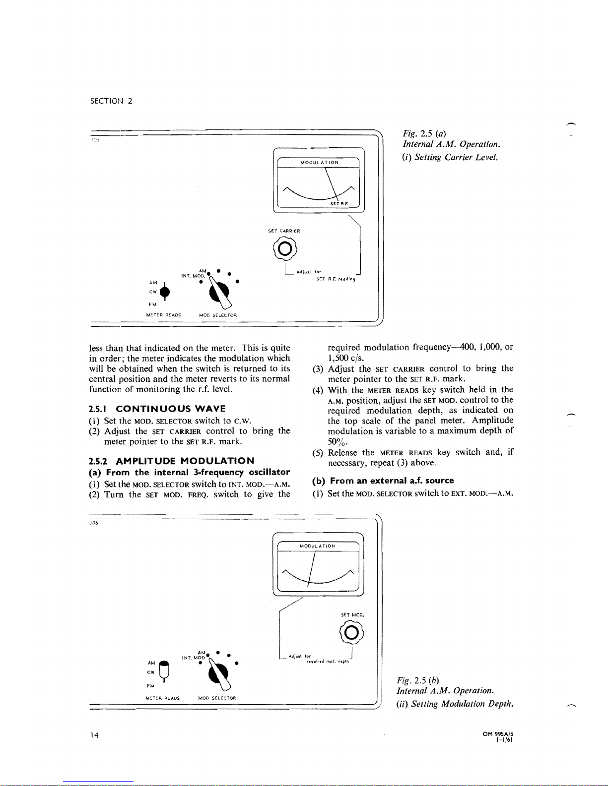
Fig.
2.5
(a)
InternaI
A.M.
Operation.
(i)
Setting Carrier Level.
MOOULATION
SET
R.r,
@
AM
•
LAdjUlt
for
_
INT'MOD
.•
~.
SET
R.F:
reading
AM.
.
~.
cw"
f M
METER READS
less than that indkated on the meter. This is quite
in order; the meter indicates the modulation which
will be obtained when the switch
is
returned to its
central position and the meter reverts to its normal
function
of
monitoring the r.f. level.
2.5.1
CONTINUOUS
WAVE
(I)
Set the MOD. SELECTOR switch to c.w.
(2) Adjust the SET CARRIER controi to bring the
meter pointer to the
SET
R.F.
mark.
2.5.2
AMPLITUDE
MODULATION
(a)
From
the
internai
3-frequency
oscillator
(I)
Set the MOD. SELECTOR switch to INT.
MOD.-A.M.
(2)
Turn the
SET
MOD. FREQ. switch to give the
required modulation frequency-400, 1,000, or
1,500 e/s.
(3)
Adjust the
SET
CARRIER controi to bring the
meter pointer to the
SET
R.F. mark.
(4) With the
METER
READS key switch held in the
A.M. position, adjust the
SET
MOD. controi to the
required modulation depth, as indicated on
the top scale
of
the panel meter. Amplitude
modulation is variable to a maximum depth
of
50%.
(5) Release the
METER
READS key switch and, if
necessary, repeat
(3)
above.
(b)
From
an
external
a.f.
source
(1) Set the MOD. SELECTOR switch to EXT.
MOD.-A.M.
f
06
MODUL A TlON
L
/
SET
MOO.
@
AM •
'--
A'j,,'
for
J
uq",tcd
mod, .tcpth
'''"o
••
~
AM
o
• •
CW
Fig.
2.5
(b)
FM
Internal
A.M.
Operation.
METER READS
MOD, .s,ElECTOA
(ii)
Setting Modulation Depth.
OM 995A/5
14
1-1/61
-------------
SECTION 2
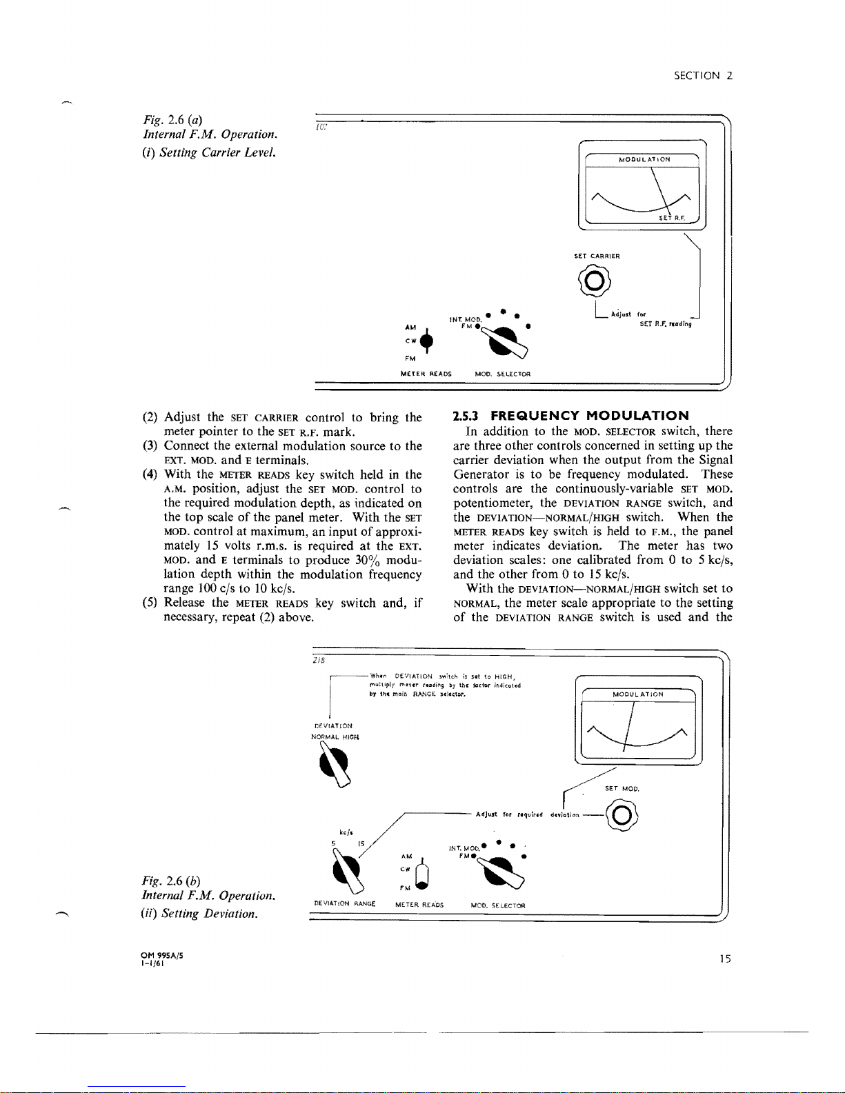
Fig. 2.6
(a)
/C7
Internai F.M. Operation.
U)
Setting Carrier Level.
SET
CA~RIER
@
Ädjust f
O(
IN1:
MOD.·
• •
SET
JU. ,..
dln9
AM+
FM.~
cw
FM
METER
READS
MOD. $E.LEcTOR
~
DEVIATION
.sw:!.::h h
set
to
HiGH~
m"ur
tlaOll'lS
by
in'
lador
jr.dico\~d
the
moin
RANCE
:s.l.ctor~
MODULATION
CE\frATtON
L
Hg. 2.6 (b)
Internai F.M. Operation.
DE
VIAT
lON
RANGE
MOO. SELECTOR
(ii) Setting Deviation.
(2)
Adjust the
SET
CARRIER controI to bring the
meter pointer to the
SET
R.F.
mark.
(3)
Conneet the externaI modulation source to the
EXT. MOD. and E terminals.
(4)
With the
METER
READS key switch held in the
A.M. position, adjust the
SET
MOD. controI to
the required modulation depth, as indicated
on
the top scale
of
the panel meter. With the
SET
MOD. controI at maximum, an input
of
approxi-
mately
15
volts r.m.s.
is
required at the EXT.
MOD.
and E terminals to produce 30% modulation depth within the modulation frequency
range
100
c/s to
10
kc/s.
(5)
Release the
METER
READS key switch and,
if
necessary, repeat
(2)
above.
2/8
2.5.3
FREQUENCY
MODULATION
In addition to the MOD. SELECTOR switch, there
are three other controls concerned in setting up the
carrier deviation when the output from the
Signal
Generator
is
to be frequency modulated. These
controis are the continuously-variable
SET
MOD.
potentiometer, the DEVIA
nON
RANGE switch, and
the
DEVIATION-NORMAL/HIGH
switch. When the
METER READS key switch
is
held to F.M., the panel
meter indicates deviation. The meter has two
deviation scales: one calibrated from
O to 5 kc/s,
and the other from O to
15
kels.
With the
DEVIATION-NORMAL/HIGH
switch set to
NORMAL, the meter scale appropriate to the setting
of
the DEVIA
nON
RANGE switch is used and the
OM
99SA/S
1-1/61
-------_
.....
_-_
....
~
15
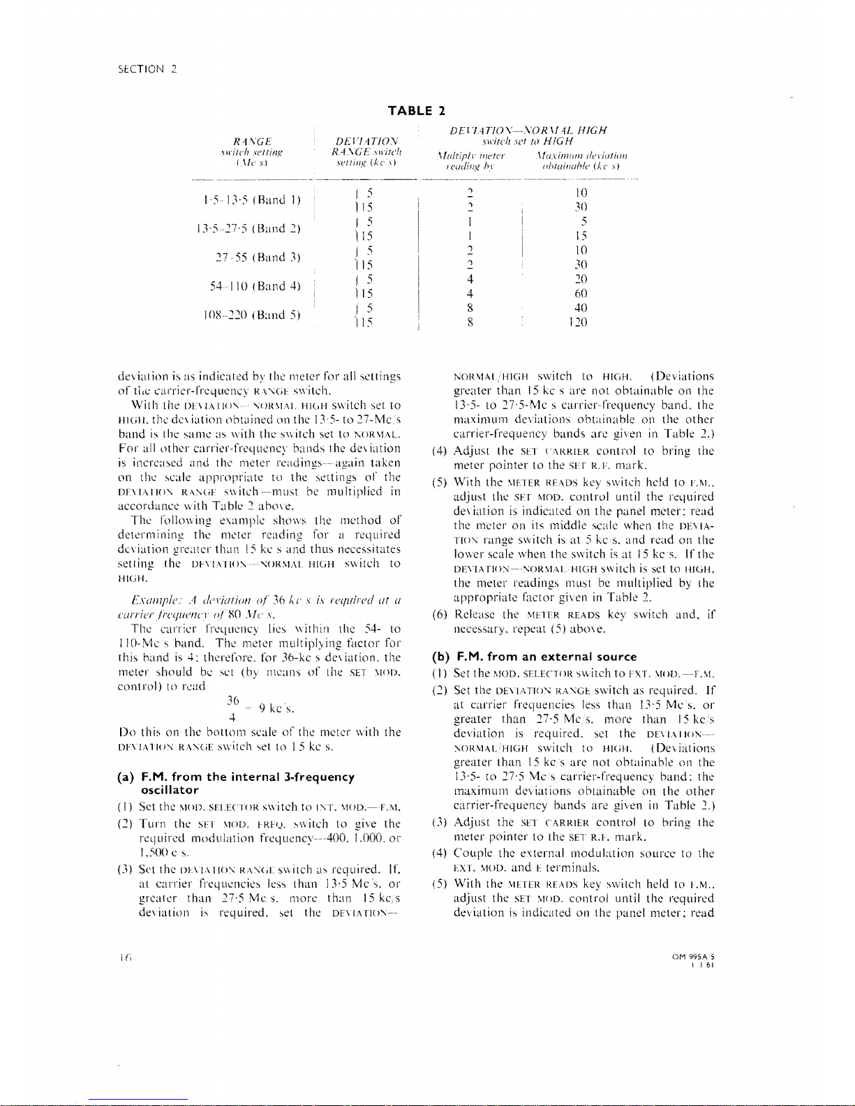
SECTION 2
R4\'GE
,\
wirch
.I'erril1g
(,\1('
sj
TABLE
2
DE
VI.4TfOV
RASGE
",,'irell
sl'rrillg (k
el)
DDI4TfO\'-VOR\f
4L
HIGH
swirch
wr
ro
HIGH
,\fl/lriplr
me/er
\/lIxi/JIIIIII deriario/l
leuding In'
o/Jlainah!c
(kc
s)
.......
_----
1'5-
1:\,5
(Rand
I)
r
5
)
15
I
~'527'5
(Band
2)
r
5
ll5
27-55
(Band
~)
I
5
'115
54-110
(Band
4)
i
5
115
IOR220
(Band
5)
f
5
115
deviation is as indicated by the
meter
ror
a\1
se!tings
or
tLe
carrier-fl'l~ljuency
R\
'\(,J',
5\\'itch.
Wilh
the
Dn
L\IIO'\
'.OR\!Al.
HIGI-I
s\\itch
set
to
111(111,
thc
de\
iation
obtained
on
the I
~'5-
to
27-Mc,;;
band
is
the
same
as with
the
switch set
to
1'.OR\L\L.
For
all \Jther
carrier-frequency
bands
the
de\
iat10n
i5
increased
and
the
meter
readings-again
taken
on
the
,cak
appropriate
to
the settings
of
the
DE\IAIIO'.
R"'.<iE
s\vitch--must
be l1lultiplied III
accordance
with
Table")
ahO\e.
The
1'0110\\
ing
cX<lmple
shows the
I11cthod
of
determining
the
meter for a required
deviation
greater
than
15
ke s
and
thus
necessitates
setting the
D~\I""()'.'-,\;()R\L\L
HIGH
s\\iteh
to
HI(iH.
EXlfl1lplc:
A c!nilll iOIl
oj
36
k
('
s is I'cquired
ilr il
('(I/'l'ier!I'('(/lImCl
o/
RO
JIe
s.
The
e<lrricr frequency lies within the 54- to
110-
Mc s hand.
Thc
metcr l11ultiply ing f;Ktor for
this
band
is
4:
therefore. for 36-kc ~ deviation.
the
meter
should
be set (by means
of
the SET :-'I()().
controI)
to
read
36
4 - 9 kc
s.
Do
this
on
the hottol1l scale
of
the meter with the
DF\ lA110:\
R":\(iE
switch
,et
to l S
kc
s.
(a) F.M. from
the
internai 3-frequency
oscillator
(I)
Set the !'>lO!).
sELECTOR
s\\iteh
LO
1:\1'.
\1UD.-LM.
(2)
Turn
the
sH
\!OD. I Rr(.l.
,,,iteh
to
the
required
modulation
freqllency~~AOO.
1.000.
or
1.500
e~.
(~)
Set the
DI\
JA
110:\
RA,\;(il
s\\ itch
a,
reqllired. If.
at
carrier
frequeneies
ks,
than
13·5
Mcs.
or
greater
than
27·S Mc
s.
more
than
15
ke,s
deviation
is
required. set the
DE\
IATlO:\--
I (i
..........
------
")
10
")
-
~()
5
15
.2
10
2
~O
4
20
4
60
8
40
II
120
NOR:\1ALHIGH
switch to
HIGH.
(Deviations
greater
than
15
kc s are not
obtainable
on the
13,5-
to 27'S-Mc s carrier-freqlleney
band.
the
maximum
deviations
obtainable
on
the
other
carrier-rrequency
bands
are
in
Table
2.)
(4)
Adjust
the
SET
CARRIER
contrnl
to bring the
meter
pointer
to
the
SH
R.F.
mark.
(S)
With
the
'.IETER READS key switch held
to
F.f>l..
adjllst the
SH
MOD.
controi
until
the
required
dc\
iation is indicated
on
the
panel meter:
read
the meter
on
its middle scale when the
DE\
IA-
TIO'\;
range switeh
is
at 5 kcs.
and
read
on
the
lo\\er
scale when the switch
is
at
15
keso
If
the
DE\'I,·\
rIO:\-~~()R\!-\L
HIGH
~\Vitch
is
set to
HIGH,
the meter readings must
be
lllultiplied by the
appropriatc
factor
gi\en
in
Table
2.
(6) Release
the
\IHlR
READS key switch
and.
if
necessury. repeat
(5)
abO\e.
(b)
F.M.
from
an
external
source
(I)
Set
the
MOD.
SELEClOR
switch
to
FXT.
\1()D.~-F.\1.
(2)
Set
the
DE\I,\TIO'.;
RA:\G~,
switch as required.
If
at
carrier
freqllencies less
than
13'5
Mes,
or
greater
than
27·S Mc S.
more
than
15
kc.s
de\'iat ion
is
req uired. set the
DE\!.\
II()]\;~
:\ORMALIIIGH
switch t o
HIGH.
(De\
iat ions
greater
than
15
kes
are
not
obtainable
on
the
13,5-
LO
27'5
\1cs
carrier-frequency
band:
the
maximum
de\' iat ions
obtainable
on the
other
carrier-fi'equency
bands
are
given
in
Table
2.)
(3)
Adjust the SET
CARRIER
controi
to
bring the
meter
pointer
to
the SET
R.I.
mark.
(4)
Couple
the externaI
modulation
source
to the
EXT.
\!OD,
and
E terminals.
(S)
With
the
\IETm
READS key switch held
to
~.M
..
adjust
the
SET
\IOD.
controi
until
the
required
deviation
is
indieated on the panel
meter:
read
OM
99SAS
I
161
thc
meter
on
its middle scnle when thc
DL\IA-
TIO'l
RANGE
switch
is
set
to
5 kc,s.
and
read
on
thc lower scale when the switch is sct
to
15
kc/s.
I f the
DE\'IA
nON-NOR
\1ALHIGH
switch is set
to
HIGH.
the
meter
rcadings must bc multiplicd by
thc
appropriate
E\ctor given in
Table
2.
For
any
scttings
of
the
DE\
IATION
RANGE
and
DEYlATlOl\:-NOR'vlALi HIGH
switches.
and
within
the
modulation
frequcncy range 50 e s
to
IS
kcs.
approximately
25
volts r.m.s.
is
required
between
the
EXT. MOD.
and
E terminals for full
deviation.
With
respect
to
I ke's.
the
frequcncy
characteristic
of
the
modulation
system
is
flat
to
within
..
c
..
I
dB
from
50 c/s
to
15
kC,s.
2.5.4
S I M U L T A N E O U S F R E Q U E N C Y
AND
AMPLITUDE
MODULATION
(I)
Sct up
the
rcquired
depth
of
amplitudc
modu-
lation as
detailed
in Section 2.5.2 (a).
(2) Leaving the MOD. SEI.ECTOR switch at
INT.
:-'10D.
-A.\1..
and
without
altering
the setting
of
the
SET MOD.
controL
set up
the
required
dcviation
in a simiJaI'
manner
to
that
detailed in Section
2.5.3
(bl;
in this case.
adjust
thc
amOllnt
of
deviation by
variation
of
the
alldio
input
from
the
extcrnal
modulation
source.
2.6
R.F.
OUTPUT
ARRANGEw
MENTS
Five factors affect
the
output
Icvel from
the
Signal
Generator
(a)
Thc
SET
CARRIER
contral
whose
setting
dcter-
mines the
input
level
to
the
attcnuator
cascade.
(bl
The'
coarse'
or
OCTPCT
\OI.TAGE
attenuator.
(c)
The'
line'
or
MCLTIPI.
y HY
attenuator.
(d)
The
TERMINATING
l'NIT
which plugs
on
the
end
of
the
output
cable
from
the
fine
attenuator.
(c)
ATTEl\L:ATOR
PAD
Type
TM
5552, which
is
an
optional
accessory designed for insertion be-
tween
the
output
cable
and
TER'yllNATlI\G
LNIT
when especially low
output
levds
are required.
The
SET
('ARRlER
controi
is
adjusted
in
conjunc-
tion with the panel
meter;
with the METER READS
key switch in its central
position.
the panel meter
forms
part
of
a crystal
voltmeter
which
monitors
the
input
to
the
coarse
attenuator.
The
panel
meter
has
three
main
marks
on
its scale; these
marks
are
I
dB,
SET R.F
..
and
I dB. respectively.
Nor-
mally. the SET
CARRIE
R contI'ol ShOllld be
adjusted
to
bring
the
meter
pointer
to
the
SET
R.r.
mark.
Four
20-dB steps give
the
coarse
or
OLTPCT
VOLTAGE
attenuator a total
range
of
80
dB:
each
setting
of
the
attenuator
controi
has
markings
in
OM
995A 5
1
161
Ii
::,ECTION 2
yellow
and
in white. the
markings
being in
decibels relative
to
I
:J.
V;
the
white
markings
are
directly in units
of
voltage.
Ten 2-dB stcps givc
the
fine
or
MUI.TlPI.Y
BY
altenuator a total
range
of
20
dB:
each
setting
of
the
attenllator
controI
has
markings
in
yellow
and
white. the ycllow
markings
being in
terms
of
deci-
bels relative to
l:"
V.
and
the
white markings,
multiplying factors for
the
white voltage
markings
on
the
cmuse
attenuator.
Both
attenuators
h,n
e a
characteristic
i l11pedance
of
75
ohms
and
..
looking
into • the
coaxial socket
at
the
end
of
the
output
cable. the
instrument
appears
as a generator
\vith a
source
impedance
of
75
ohms
at
all
attenllator
The
TERMINATJNG
LNIT
is. essentially. a 6-dB
attenuator
pad: . looking
into'
ilS
input
socket,
with
ilS
output
sockets lInterminated. the
TERMI-
NATI1\:G C:-;IT
prescnb
an
impedance
of
75
ohms.
while
the
two
outlets
present impedances
of
52
and
75
ohms
respectively.
The
ATTEI\:CATOR
PAD
has a
characteristic
impe-
dance
of
75
ohms
and
provides
an
optional,
additional.
20-dB
attelluation
of
thc
output
signal.
[t
should
be
noted
particularly
that
the r.f.
out-
put
contro!s
on
the Signal
Generator
are
calibratcd
in terms
of
source
c.mJ.
or
open-circuit
output
voltage.
The
significance
of
quoting
the
output
of
a signal
generator
in
this
way will be
apparent
when
il
is
rel11el11bered
that
one
of
the
primal')' functions
of
a signal
generator
is
to
simulate
a rcceived signal
as it would
come
fram
an
aeda!.
To
take
a simple
case-that
in which a
75-ohm
receiver
is
fed from a 75-ohm
dipole-the
e.m.f.
induced in the aerial
is
shared
between ils
inherent
75-ohm
radiation
resistance
and
the
matched
75-ohm
rccei\l;~r
input.
Clearly. when
the
samc
receiver is fed from a signal
generator.
the
corre-
sponding
signal
strength
is given by
the
source
e.m.f.
of
the
generator.
and
not
by the
on-
load
p.d.
at
the
receiver terminals.
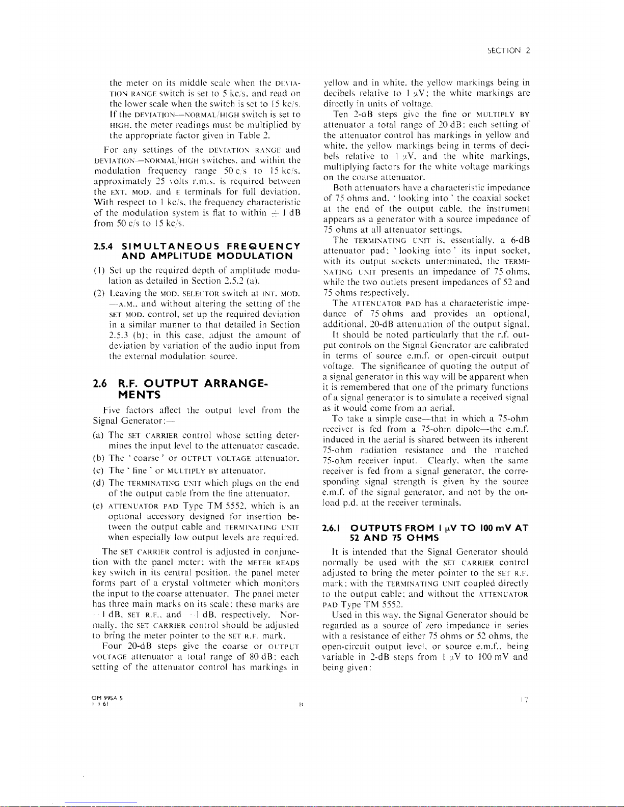
2.6.1
OUTPUTS
FROM I ",V
TO
100
mV
AT
52
AND
75
OHMS
Il
is
intended
that
the Signal
Generator
should
normally be used with the
SET
('ARRlER
controi
adjusted
to
bring the meter
pointer
to
the
SET R.F.
mark:
with the
TER\lINATI'lG
lNIT
coupled
directly
to
the
output
cable:
and
without
the
ATTF:-':CATOR
PAD
Type
TM
5552.
Used in this way.
the
Signal
Generator
should
be
regarded
as a source
of
zero
impedancc
in series
'vith a
re,istance
of
either
75
ohms
or
52
ohms,
the
open-circllit
output
level.
or
source
e.m.r.. being
variable in 2-d B stcps from I
:J,V
to
100 m
Vand
being given:
17
• •
• •
SECTIOt~
2
~2o'"
52S1
40dS
lOdS
IOOjJV
3-1
II-------;;~
,.~.:".,
....
.~.
.~
•• O ••
T
_____
20
-=
7S.o
MUI..TIPLY SY
/0/
Fig.
2.7 Outputs
via
Terminating Uni!.
(a) directly in terms
of
decibels relative to I fLV, by
the sum
of
the yellow settings
of
the OUTPUT
VOLTAGE
and MULTIPLY
BY
attenuators;
(b)
dire:ctly
in
voltage, by the product
of
the white
settings
of
the
OUTPUT
VOLTAGE and MULTIPLY
BY
attenuators.
The
+l-dB and
-l-dB
marks on the panel meter
allow interpolation between the 2-dB steps
of
the
MULTIPLY
BY
attenuator. Setting the meter pointer
to eithf:r the
+l-dB or
-l-dB
mark increases
or
decreases the input
to
the attenuator cascade by
l decibel. Thus, using the
SET
CARRIER controi and
panel meter in conjunction with the
OUTPUT VOLT-
AGE
and MULTIPLY
BY
attenuators, the output level
from the Signal Generator can be varied in l-dB
steps over the range
Oto +
100
dB relative to l fLV.
It
should
be
noted that the white voltage indica-
tion given
by
the attenuator controls
is
not directly
applicable when the meter
is
set to other than the
SET
R.F. mark; with the meter at l dB, the source
e.m.f.
at
the TERMINATING UNIT outlets is 0·89
of
the indicated voltage; with the meter
at
+l dB, the
source e.m.f.
is
1·12
of
the indicated voltage.
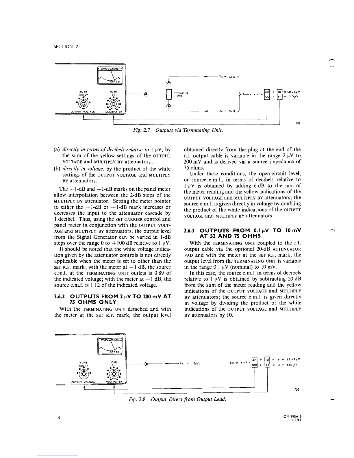
2.6.2
OUTPUTS
FROM 2
\lV
TO
200
mV AT
75
OHMS
ONLY
With the TERMINATING UNIT detached and with
the meter at the
SET R.F. mark, the output level
4048
10dB
3-1
IOOpV
....
.
~.
.({®
•• O •
•
obtained directly from the plug at the end
of
the
r.f. output cable is variable in the range 2
fL
V to
200 m
Vand
is derived via a source impedance
of
75
ohms.
Under these conditions, the open-circuit level,
or source e.m.f., in terms
of
decibels relative to
l
fL
V
is
obtained
by
adding 6
dB
to the sum
of
the meter reading and the yellow indications
of
the
OUTPUT VOLTAGE and MULTIPLY BY attenuators; the
source e.m.f.
is
given directly in volta
ge
by
doubling
the product
of
the white indications
of
the OUTPUT
VOLTAGE
and MULTIPLY
BY
attenuators.
2.6.3
OUTPUTS
FROM
O.l
....
V
TO
10
mV
AT
52
AND
75
OHMS
With the TERMINATING UNIT coupled to the r.f.
output cable via the optional 20-dB
ATTENUATOR
PAD
and with the meter
at
the SET
R.F.
mark, the
output level from the
TERMINATING UNIT
is
variable
in the range
0·1
fLV (nominal) to
10
mY.
In
this case, the source e.m.f. in terms
of
decibels
relative to l
fL
V
is
obtained
by
subtracting
20
dB
from the sum
of
the meter reading and the yellow
indications
of
the
OUTPUT
VOLTAGE and MULTIPLY
BY
attenuators; the source e.m.f. is given directly
in voltage by dividing the product
of
the white
indications
of
the OUTPUT VOLTAGE and MULTIPLY
BY
attenuators by 10.
+ 10 + 6 = S6
dSpV
x
3-1
X 2 =
.20
pV
Ffg.
2.8 Output Direct from Output Lead.
OM 99SA/S
1-1/61
18
M\)LTIPLY
SV
102
 Loading...