

Marconi Instruments TF 2700 Instructions Manual

OPERATING INSTRUCTIONS
EB 2700
for
Universal Bridge
TF 2700
Copyright @ 1962
MARCONI INSTRUMENTS LIMITED
STo ALBANS HERTFORDSHIRE ENGLAND
C. P. lk EB 2700
3/66/K 19 - 3/66
CONTENTS
Section Page
l GENERALINFORMATION ... ... ... 3
1.1 Features o.. ... ... ... ...3
l.l DataSummary ... ... ... ... 4
1.3 Optional Accessories ... ... ... ... 6
l OPERATION o.. ... ... ... ... 7
l.l GeneraI... ... ... ... ... 7
l.l.l Balancing the Bridge ... ... ...7
l.l. l Reading the Result ... . .. . . . . . . 8
l.l BatteryCheck... ... ... ... 0..9
l.3 Connections ... o.. ... ... ...9
Fig. l.3 Controls and Operating Faci1ities . . . . . . lO
l.4 Capacitance Measurements ... ... .'. Il
l.4.1 -using the Interna11 kc/sSource ... ... Il
l.4.l -usinganExterna1A.F. Source ... o.. 13
l. 4.3 E 1ectro1ytic C apacitors and use of Po1arizing Bias 13
l.4.4 CapacitancetoTrueEarth o.. ... ...14
l.5 Inductance Measurements ... ... ... 15
l.5.1 -using theInterna11 kc/s Source ... ... 15
l.5.l -using anExterna1A.F. Source ... ... 16
l. 5. 3 IncrementaI Inductance and use of Polarizing Bias 16
l.6 Resistance Measurements ... ... o.. lO
l.6.1 -usingtheInternallkc/sSource ... ... II
l. 6. l -using an External A. F. Source . . . o . . II
l.6.3 -using the InternaI B atte ry ... ... ... II
l.6.4 -usinganExterna1D.C. Source o.. ... l3
l.7 Connection of Externa1 A. C. Source o . . . .. l5
l.8 LossBalance-QorD... ... ... ...l7
3 CIRCUIT SUMMARY ... ... ... ... l8
3.1 Bridge Circuits ... ... ... ... l8
3. l Bridge Energizing Sources . .. . .. . . . 19
3.3 Detector ... ... ... ... ... 19
4 MAINTENANCE NOTES. . . . . . . . . . . . 31
4.1 Replacement o£the Battery ... o.. ...31
4. l Replacement of Circuit Componente . .. . .. 31
4. l. 1 Access to Interior . o. . . . . . . . . . 31
4. l. l Adjustment o£ Detector Sensitivity . . . o . . 3l
4.l.3 Oscillator Frequency ... ... ... 3l
4.l.4 RangeResistorRI3... ... ... ... 3l
CIRCUIT DIAGRAM . . . . . . inside back cover
2
I GENERAL INFORMA TION
1.1 FEATURES
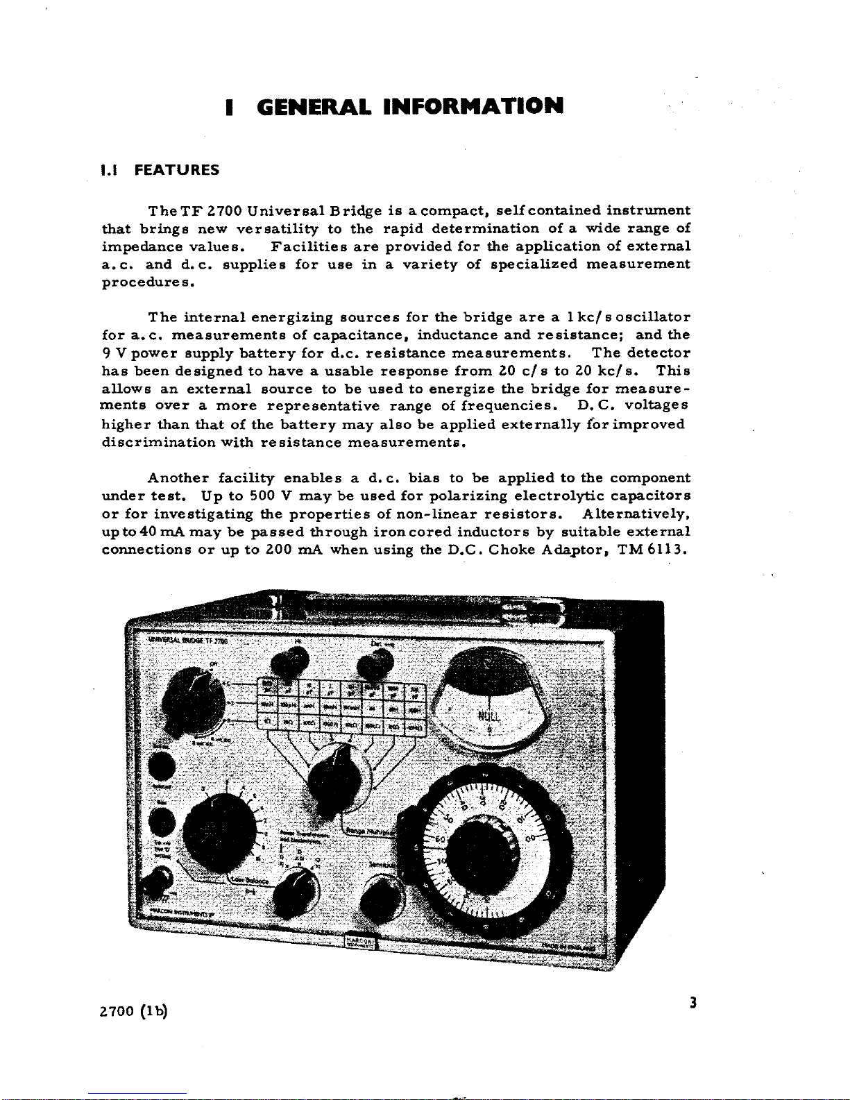
The TF 2700 Universal Bridge is a compact, self contained instrmnent
that brings new versatility to the rapid determination of a wide range of
impedance values. Facilities are provided far the application of external
a.c. and d.c. supplies far use in a variety of specialized measurement
procedures.
The internaI energizing sources far the bridge are a 1 kc/ s oscillator
far a. c. measurements of capacitance, inductance and resistance; and the
9 V power supply battery far d.c. resistance measurements. The detector
has been designed to have a usable response from 20 c/s to 20 kc/s. This
allows an external source to be used to energize the bridge far measure-
menta aver a more representative range of frequencies. D. C. voltages
higher than that of the battery may alBo be applied externally {or improved
discrimination with re sistance measurement&.
Another facility enables a d. c. bias to be applied to the component
under test. Up to 500 V may be used far polarizing electrolytic capacitors
or far investigating the properties of non-linear resistors. Alternatively,
upto 40 mA may be passed through iron cored inductors by suitable external
connections or up to 200 mA when using the D.C. Choke Adaptor, TM 6113.
2700 (1 b) 3
~ '-
1.2 DATA SUMMARY
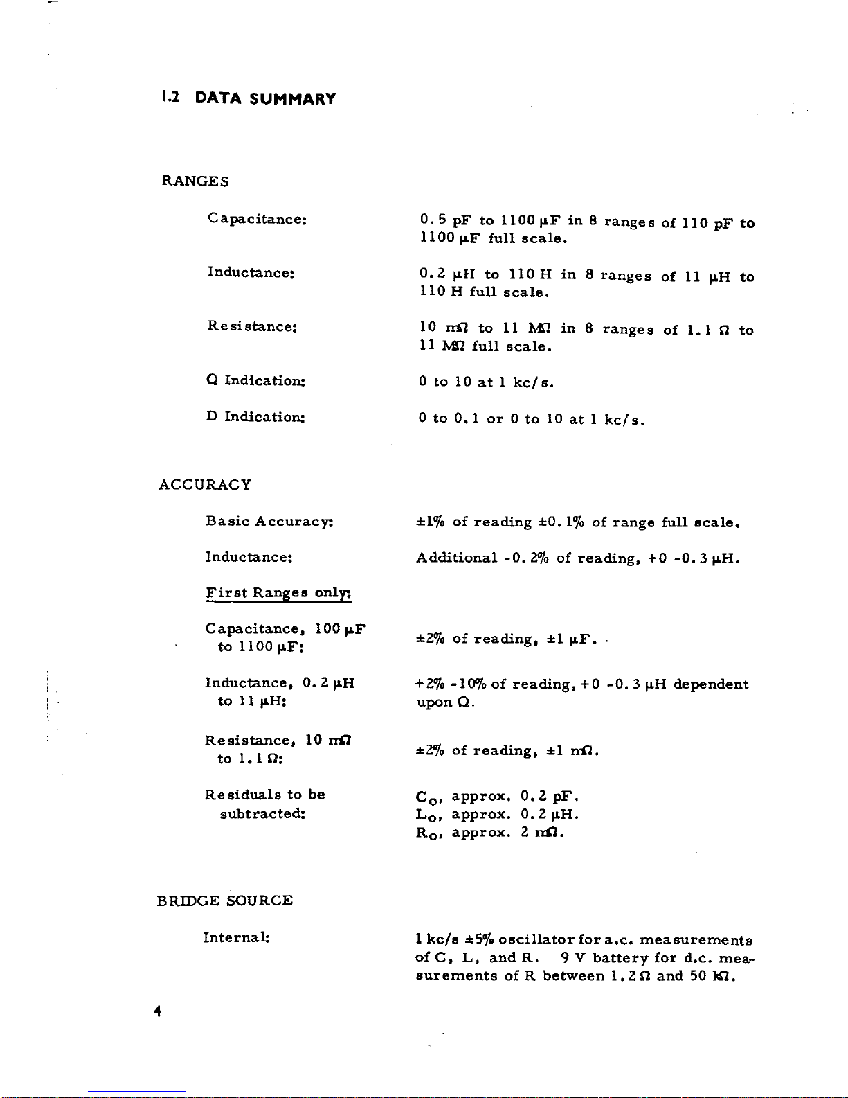
RANGES
C apacitance: O. 5 pF to 1100 I1F in 8 range s of 110 pF to
1100 I1F full scale.
Inductance: O. 2 I1H to 110 H in 8 range s of Il I1H to
110 H full scale.
Resistance: lO ni1 to Il M1 in 8 ranges of 1.1 a to
Il MrZ full scale.
Q lndication: O to lO at l kc/s.
D Indication: O to 0.1 or O to lO at l kc/s.
ACCURACY
Basic Accuracy: :1:1% of reading :1:0. 1"/0 of range full scale.
Inductance: Additional -0.2"/0 of reading. +0 -0.3 I1H.
First Ranges only:
Capacitance. 100 I1F
201 f d.
:1:1 Fto 1100 I1F: :I: IO o rea lng. jJ...
Inductance. 0.2jJ.H +2"/0 -10"/0 of reading. +0 -O. 3jJ.H dependent
to lljJ.H: upon Q.
Resistance. lO ~
201
f di :1:1 -..n
l :I: IO o rea ng. LLA'.
to l. a:
Residuals to be COI approx. O.l pF.
subtracted: Lo. approx. 0.2 jJ.H.
Ro. approx. 2~.
BRIDGE SOURCE
InternaI: l kc/s :1:50;0 oscillator far a.c. measurements
of C. L, and R. 9 V battery for d.c. me a-
surements of R between 1.2 a and 50 ~.
4
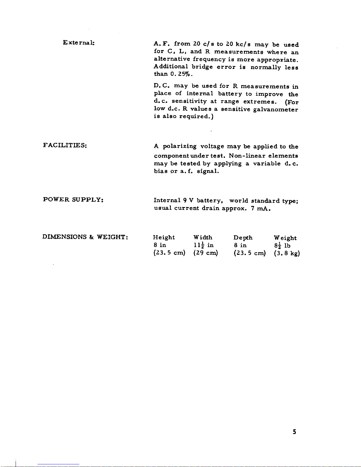
E xte rnal: A. F. tram 20 cl s to 20 kcl s may be used
far C. L. and R measurements where an
alternative frequency is more approp~iate.
Additional bridge errar is normally lesa
than O. 25% .
D.C. may be used far R measurements in
piace of internaI battery to improve the
d. c. sensitivity at range extremes. (For
low d.c. R values a sensitive galvanometer
is alBo required.)
FACILITIES: A polarizing voltage may be applied to the
component under test. N on-linear elements
may be tested by applying a variable d. c.
bias or a. f. signal.
POWER SUPPLY: InternaI 9 V battery. world standard type;
usual current drain approx. 7 mA.
DIMENSIONS &. WEIGHT: Height Width Depth Weight
8 in llj in 8 in 8j lb
(23.5 cm) (29 cm) (23.5 cm) (3.8 kg)
5
I.] OPTIONAL ACCESSORIES
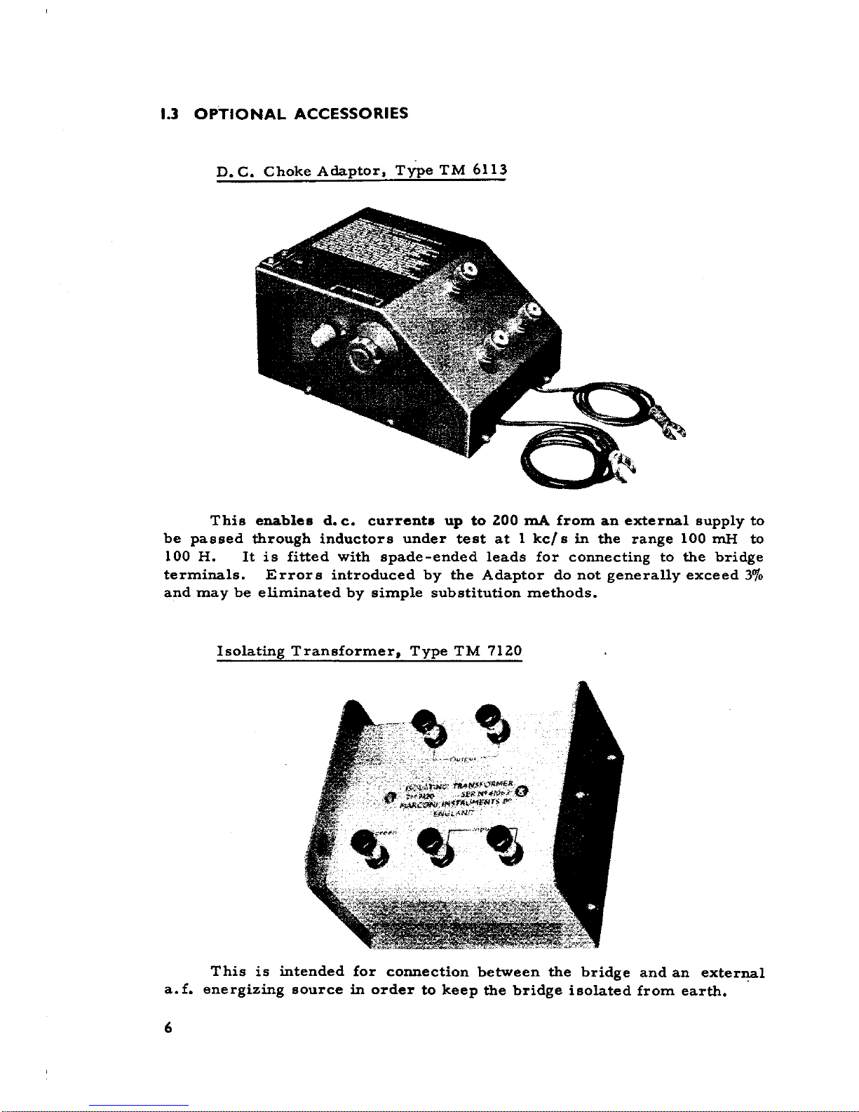
D. C. Choke Adaptor. TiPe TM 6113
This enables d. c. currenta up to ZOO mA from an external supp1y to
be passed through inductors under test at 1 kcl s in the range 100 mH to
100 H. It is fitted with spade-ended leads far connecting to the bridge
termina1s. Errors introduced by the Adaptor do not genera11y exceed 3%
and may be eliminated by simple substitution methods.
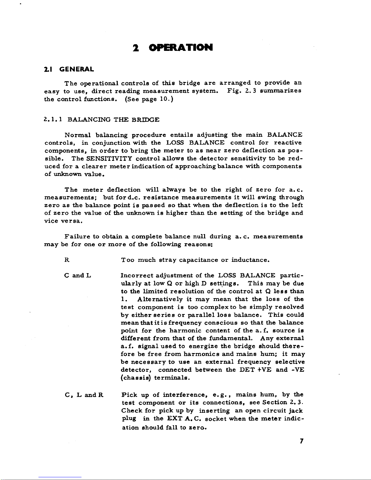
Isolating Transformer, Type TM 71Z0
This is intended far connection between the bridge and an externa1
a.f. energizing source in arder to keep the bridge isolated from earth.
6
2 OPERA nON
2.1 GENERAL
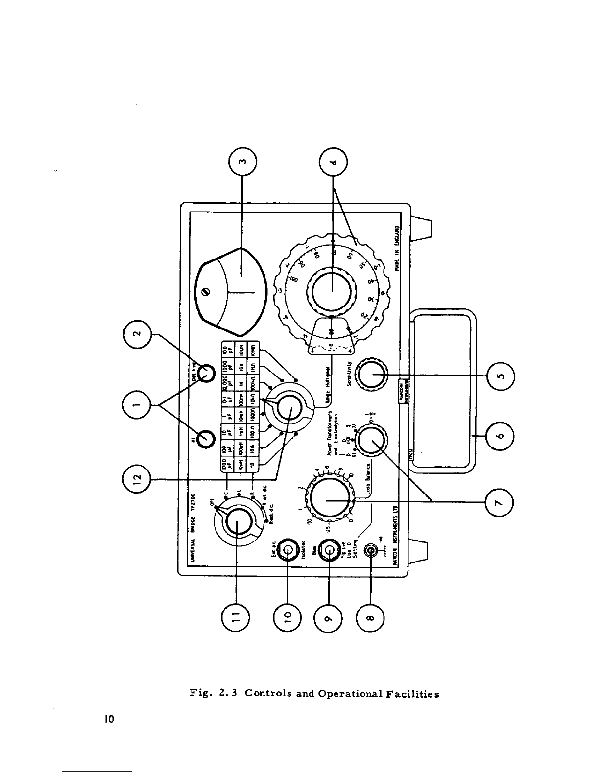
The operational controls of this bridge are arranged to provide an
easy to use, direct reading measurement system. Fig. 2.3 summarizes
the control functions. (See page lO.)
l.l.l BALANCING THE BRIDGE
N ormaI balancing procedure entails adjusting the main BALANCE
controls, in conjunction with the LOSS BALANCE control for reactive
components, in arder to bring the meter to as near zero de£lection as possible. The SENSITIVITY control allows the detector sensitivity to be red-
uced for a clearer meter indication of approaching balance with components
of unknown value.
The meter de£lection will always be to the right of zero for a. c.
measurements; but ford.c. resistance measurements it will swing through
zero as the balance point is passed so that when the de£lection is to the left
of zero the value of the unknown is higher than the setting of the bridge and
vice versa.
Failure to obtain a complete balance null during a. c. measurements
may be for one or more of the foliowing reasons:
R Too much stray capacitance or inductance.
C and L Incorrect adjustment of the LOSS BALANCE partic-
ularlyat low Q or high D sett_ings. This may be due
to the limited resolution of the contrai at Q lese than
l. Alternatively it may mean that the loss of the
test component is too complex to be simply resolved
by either series or paralielloss balance. This could
mean that it is frequency conscious so that the balance
point for the harmonic content of the a. f. source is
different tram that of the fundamental. Any external
a. f. signal used to energize the bridge should therefore be free tram harmonics and mains hum; it may
be necessary to use an external frequency selective
detector, connected between the DET +VE and -VE
(chassis) terminals.
C, L and R Pick up of interference, e. g., mains hum, by the
test component or its connections, see Section l.3.
Check for pick up by inserting an open circuit jack
plug in the EXT A. C. socket when the meter indication should fali to zerG.
7
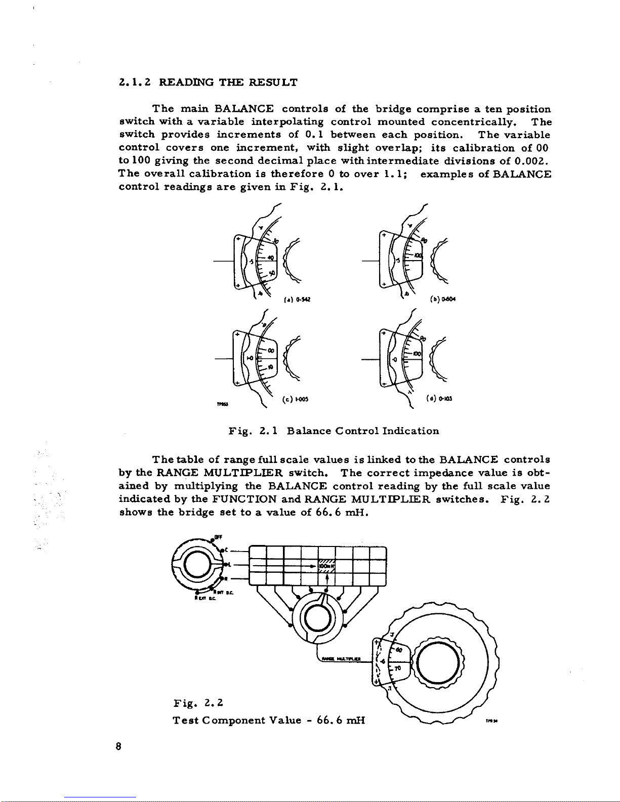
2..1.2. READING THE RESULT
The main BALANCE controls of the bridge comprise a ten position
switch with a variable interpoIating contraI mounted concentrically. The
switch provides increments of O. l between each position. The variable
contraI covers one incremento with slight overIap; its calibration of 00
to 100 giving the second decimaI piace withintermediate divisions of 0.002..
The overall calibration is therefore O to aver 1.1; examples of BALANCE
contraI readings are given in Fig. 2.. l.
( (
c.}o.s.. (o) 00604
QJ( (
(c) ,- (o) 0-.0.
Fig. 2.. l BaIance ContraI Indication
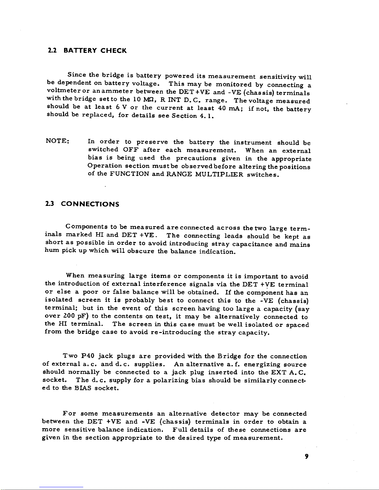
The table of range full scale values is linked to the BALANCE controls
by the RANGE MULTIPLIER switch. The correct impedance value is obtained by multiplying the BALANCE contraI reading by the fun scale value
indicated by the FUNCTION and RANGE MULTIPLIER switches. Fig. 2.2
shows the bridge set to a value of 66.6 mH.
...
~
""K
Fig. 2.2
Test Component Value - 66.6 mH
8
2.2 BATTERY CHECK
Since the bridge is battery powered its measurement sensitivity will
be dependent on battery voltage. This may be monitored by connecting a
voltmeteror anammeter between the DET+VE and -VE (chassis) terminals
with the bridge set to the lO M.'"2, R INT D. C. range. The voltage measured
should be at least 6 V or the current at least 40 mA; if not, the battery
should be replaced, far details see Section 4. l.
NOTE: In arder to preserve the battery the instrument should be
switched OFF after each measurement. When an external
bias is being used the precautions given in the appropriate
Operation section mustbe observed before altering the positions
of the FUNCTION and RANGE MULTIPLIER switches.
2.3 CONNECTIONS
Components to be measured are connected across the two large term-
inals marked HI and DET + VE. The connecting leads should be kept as
short as possible in arder to avoid introducing stray capacitance and mains
hum pick up which will obscure the balance indication.
When measuring large items or componente it is important to avoid
the introduction of external interference signals via the DET +YE terminaI
or else a poor or false balance will be obtained. li the component has an
isolated screen it is probably best to connect this to the -VE (chassis)
terminaI; but in the event of this screen having too large a capacity (say
aver 200 pF) to the contents on test, it may be alternatively connected to
the HI terminaI. The screen in this case must be well isolated or spaced
from the bridge case to avoid re-introducing the stray capacity.
Two P40 jack plugs are provided with the Bridge far the connection
of external a. c. and d. c. supplies. An alternative a. f. energizing source
should normally be connected to a jack plug inserted into the EXT A. C.
socket. The d. c. supply far a polarizing bias should be similarly c onne cted to the BIAS socket.
For some measurements an alternative detector may be connected
between the DET +VE and -VE (chassis) terminals in arder to obtain a
more sensitive balance indication. Full details of these connections are
given in the section appropriate to the desired type of measurement.
9
~
i
~
i
Fig. Z.3 Controls and Operational Facilities
IO
 Loading...