


8720A-4
Technical
Manual
THERMAL CAMERA
P4428
© Marconi Applied Technologies Limited
This report, which is released on the
understanding that the Company’s
proprietary rights therein are recognised
and that it is solely for the information of
the recipient, must not be copied either as
a whole or in part, or disclosed to any
third party or used as the basis for the
manufacture or sale of apparatus, without
prior written permission from the Company.

CONTENTS
FRONT FOLD
Section 1 General Descriptions Page
Picture of Complete P4428 1
Brief Specification 2 - 4
Operating and Technical Descriptions 5 - 13
Internal Assembly Details 14 - 18
Batteries 19 - 23
Camera Disassembly and Tube replacement 24 - 25
Modification Record 26 - 27
Section 2 Fault Finding and Setup
Primary Fault Check Procedures 28 - 32
Camera Electrical Set -Up 33 - 35
REAR FOLD
Section 3 Diagrams
Block Diagram 1
Circuit Diagrams and Layouts :
1) Scan and Monitor Board (Old & New) 2 - 6
2) Video Processing Board (Old & New) 7 - 10
3) Voltage Regulator Board (Old & New) 11 - 14
Parts Lists
Scan and Monitor Board (Old & New) 15 - 21
Video Processing Board (Old & New) 22 - 28
Voltage Stabiliser Board (Old & New) 29 - 31
Voltage Stabiliser Unit (Old & New) 32
Chassis 33
Yoke Assembly 34
Front Plate Assembly 35
Case 36
Battery Cartridges 37
Battery Substitution Unit 38
Accessories 39
Section 4
Detailed Fault Checklists 40 - 60
Waveforms 61 - 71
- 1 -
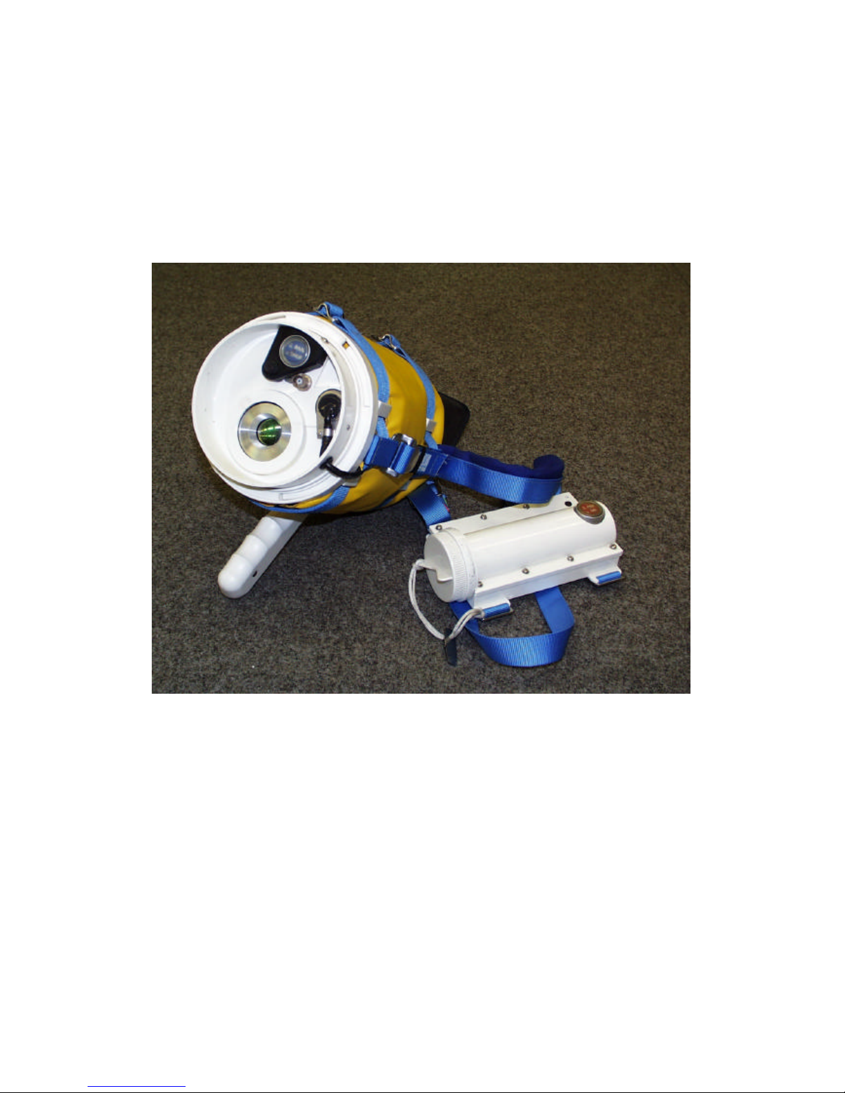
P4428 Pyroelectric Vidicon Camera
Complete with Voltage Stabiliser Unit
Specification
- 2 -
SPECIFICATION
1. Camera
The camera has been designed to operate in the hostile conditions
encountered in a fire-fighting environment.
Weight 3.0Kg (camera including muff and harness)
Material Case - Polycarbonate
Harness - Nylon
Muff PVC/Nylon flame retardant - felt liner
Visor Neoprene
Immersion The camera will withstand driving spray and total
immersion in water.
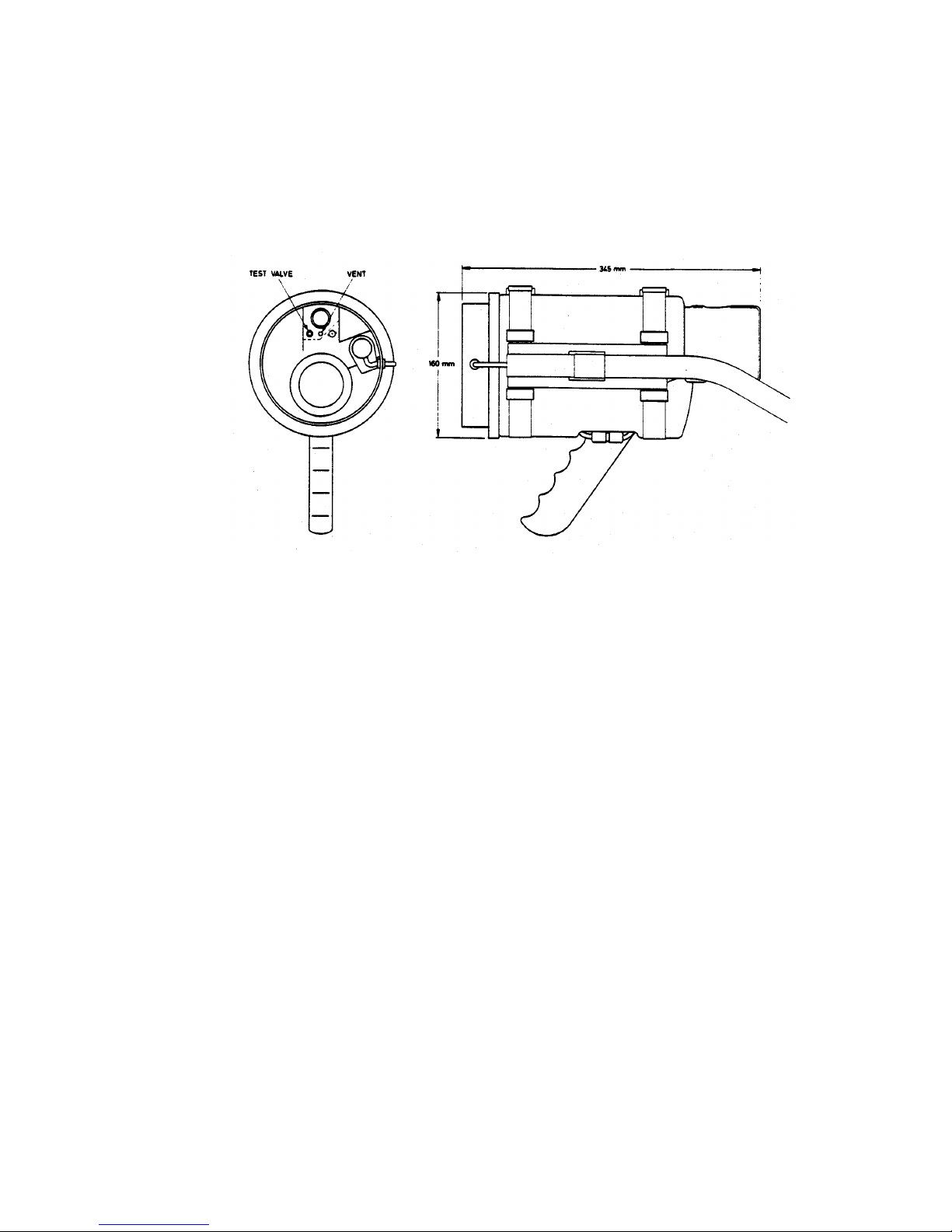
Case Sealing A test valve is provided so that sealing tests may
be executed using a vacuum pump.
A vent is also included which releases at an
internal excess pressure of 7 p.s.i.
Electrical
Power 3.7W Nominal
Voltage range 8.7V D.C. input
Battery life 10 size AA alkaline disposable cells - typically 2
hours.
10 size AA Nickel Cadmium rechargeable cells -
typically 1 hour.
(Note: rechargeable cells may need to be fully
cycled a few times to achieve maximum charge
capacity.)
Video The external video signal is nominally 1 Volt 625
lines 50Hz (CCIR compatible) or 525 lines 60 Hz
75Ω termination set at manufacture.

Specification
- 3 -
Temperature Resolution
200 lines per picture height for a temperature difference of 2EC (Chopped) -
1EC (Panned).
Lens
The lens has a hard anti -reflection coating and may be cleaned as necessary
with an appropriate soft cloth.
Focal length 18mm, f/0.8
Angle of View 57E
Spectral Response 8 to 14µm
P8092 pyroelectric vidicon PEVICON manufactured by Marconi Applied
Technologies Limited.
Electromagnetic Compatibility CE
The camera and VSU of cameras serial number above 6000 comply with the
requirements of EU directive 89/336 EEC.
Specification
- 4 -
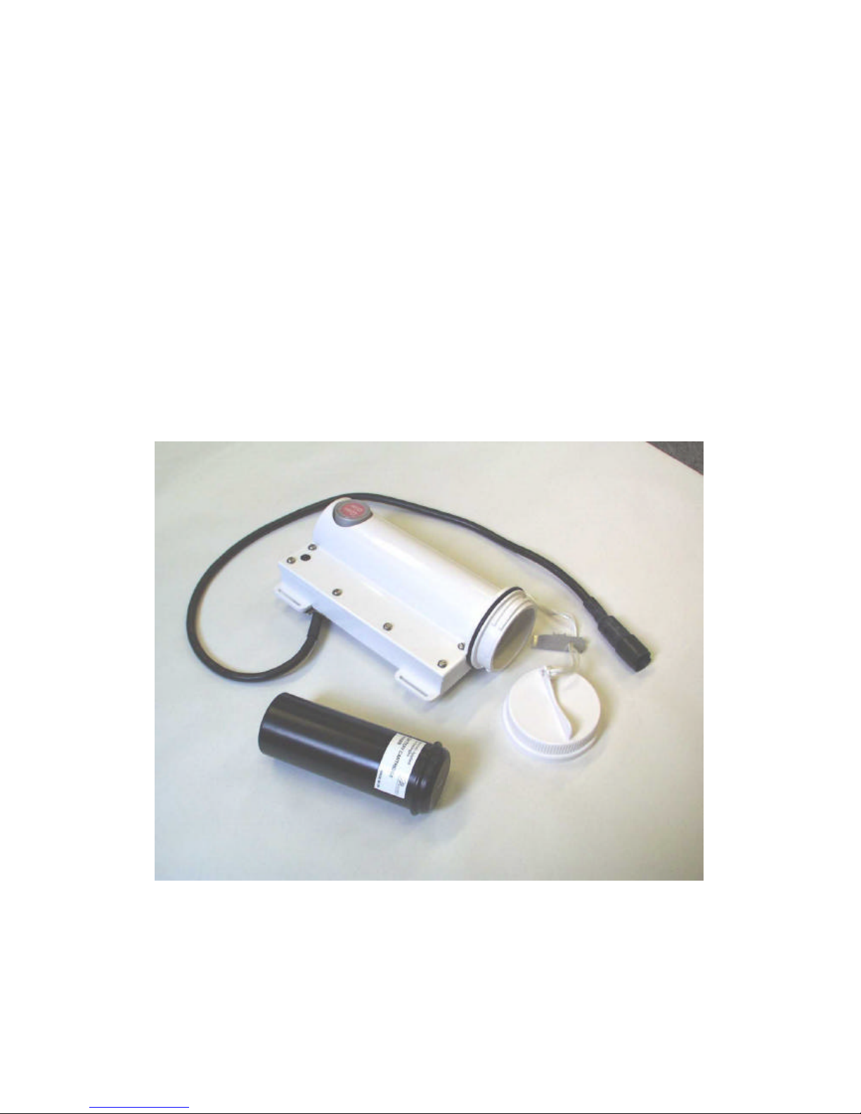
2. Voltage Stabiliser
Mechanical
Weight 0.5Kg (less batteries)
Material Polycarbonate
Electrical
Input 9.5 to 15 volts
Output 8.7V @ 400mA D.C.
P4428K Voltage Stabiliser

Operating and Technical Descriptions
- 5 -
P4428 GENERAL DESCRIPTION
The P4428 hand -held thermal imaging camera uses the P8092 pyroelectric
vidicon, and provides a thermal television picture in the 8 to 14 micron
radiation band. It is enclosed in a sealed injection moulded polycarbonate
case and is intended for use in fire-fighting applications. The camera is a self
contained unit with a wide-angle germanium lens, giving a viewing angle of 57
degrees, with an integral viewfinder/monitor. The camera is fully automatic
with operation selection of 'Panned' or 'Chopped' mode of operation. Power is
provided by a reloadable battery cartridge which fits into the voltage stabiliser
unit attached to the camera harness. A video output socket is provided for
remote surveillance.
Where difference exist between the versions of camera those for the surface
mount board set (SMT) are given in square brackets [................].
1. ELECTRICAL SPECIFICATION
1.1. Power Requirements
The equipment requires a 9.3 to 15 volt supply at approximately 0.4
amps. A battery cartridge is provided which uses 10 standard 'AA' size
1.5 volt disposable alkaline cells.∗ The output from this pack is 15 volts
nominal and is regulated to 8.7V and current limited to 700mA by the
voltage stabiliser unit. At least 1.5 hours operation is possible on each
set of batteries. For use with external power supplies an adaptor is
available.
Alternatively 10 rechargeable AA cells (type NCC-50) may be used
with a reduced operating time of approximately 1 hour, depending on
cell capacity.
∗
See also Appendix 1.
1.2. Video Output
Composite video is supplied to an internal viewfinder/monitor. A BNC
video output socket is provided for an external monito r. This requires a
75Ω termination. Circular blanking is added to obscure edge effects of
the over-scanned target.
1.3. Performance
In the panned mode the temperature resolution at the centre of the field
of view is less than 0.5EC differential scene temperature at a spatial
resolution of 100 TV lines and better than 0.2EC at 20 TV lines,
assuming unity emissivity. (See also P8092 data sheet).

Operating and Technical Descriptions
- 6 -
2. MECHANICAL SPECIFICATION
2.1. Dimensions
Camera: 27cm x 17cm dia. (excluding pistol grip and visor)
Voltage Stabiliser Unit: 18cm x 6.5cm x ll.5cm
2.2. Weight
Camera: (including harness, muff, visor and pistol grip) 3.0kg
Voltage Stabiliser Unit: (less batteries) 0.5kg
2.3. The camera case comprises a two part polycarbonate moulding
retained by a breech type locking ring.
The voltage stabiliser unit is a polycarbonate moulding.
3. OPERATING MODES
The signal is proportional to the rate of change of the temperature of
the pyroelectric target and decays within 10 seconds of exposure. To
obtain a continuous signal from a stationary object a shutter is used to
obscure the target at field rate. Alternatively the image - or camera may be moved or panned.
3.1. Shutter
A rotating shutter is incorporated into the front of the camera. It is
synchronous in rate and phase with the camera scanning beam. The
images obtained are alternately inverted in polarity. They are
synchronously re-inverted and balanced in the video channel to give
continuous positive images. Shading correction circuits aid balance
between the signals and minimise flicker.
4. LINE FLYBACK GAS PEDESTAL
The ion pedestal within the tube is enhanced by increasing the beam
current during line flyback, i.e. by pulsing Gl positively. By this means a
larger signal is obtained from the tube. An automatic circuit detects and
regulates the ion pedestal.
5. OPERATING PROCEDURE
Plug the battery cartridge into the voltage stabiliser ensure the
connection between the stabiliser and camera is made, then switch on.
A satisfactory operating voltage is confirmed by observing that the
LEDs in the viewing window illuminate. A circular image will now be
obtained after a target discharge period and the camera chopped or
panned operating mode may be selected as required.

Operating and Technical Descriptions
- 7 -
6. COMPLETE SET UP FOR NEW TUBE
6.l. Replacing Tube
See Appendix 2.
6.2. Gl and Pedestal Control Adjustments
These controls are adjusted using the values of I G4 (BEAM) and I G4
(BEAM + PEDESTAL) pre-determined for each tube during factory test
to obtain a specific value of pedestal current. Using the jack lead and a
micro-ammeter, plug the jack into the Ig4 socket (Scan board). Turn
the pedestal amplitude control (Scan board RV110), fully clockwise
[anticlockwise SMT boards] for minimum Ig4; adjust the G1 control
(Scan board RV111), for recommended I G4 (BEAM) value and then
increase the reading to the recommended I G4 (BEAM + PEDESTAL)
value using the pedestal amplitude control.
Typical Values: I G4 (BEAM) = 4µA
I Gg4 (BEAM + PEDESTAL) = 11µA
Alternatively if relevant figures are not available for the tube, firstly
adjust IG4 current for 4µA as instructed in the previous paragraph.
Monitor the head amplifier output voltage on an oscilloscope and adjust
the pedestal control for a forward line scan pedestal of 175mV.
NB The I G4 (BEAM + PEDESTAL) value can be noted for future
reference.
6 3. Picture Acquisition
An image will normally be obtained with the camera controls
undisturbed from the previous tube. Set the camera to 'pan' mode.
Turn the circular blanking control slightly anticlockwise to display the
entire target image. Adjust the line and field shading pre-sets for
minimum shading either by inspecting the picture or preferably by
displaying the relevant field/line video waveforms on an oscilloscope.
Adjust for minimum shading using the parabola and tilt correction
waveforms. Switch to 'chop' and cover the lens. The black level control
may now be adjusted for a signal level of 1.5V on the oscilloscope.
This provides optimum range for the output level clamp. Shading may
sometimes be further improved by re-orientating the tube for minimum
symmetrical shading. If this is necessary the picture acquisition section
will have to be repeated.

Operating and Technical Descriptions
- 8 -
7. OPERATING FACILITIES AND ADJUSTMENTS
7.1. Electrode Supplies
Pre-set controls are located on the scan board.
i) G2 Fixed voltage 175 volts
ii) G3 Pre-set for 80 volts (RV109)
iii) G4 Fixed voltage 135 volts
iv) G1 Variable from 0 to -60 volts (RV111)
v) Target (CPS) Pre-set to 0 volts
7.2. 8.7 Volt Supply
This basic supply is pre-set in the voltage stabiliser unit (VR400 [VR1]).
7.3. Magnetic Focus
The control is located on the scan board (RV116).
NB The magnetic focus control should be used to adjust the tube
electrical focus in preference to varying G3.
7.4. Line Linearity
A saturable reactor is used to control the line linearity and width. It is
located on the scan board (L100). [SMT version requires turns to be
adjusted]
7.5. Scan Adjustments
The following controls are provided:
horizontal shift RV101; vertical amplitude RV112; vertical shift RV113.
7.6. Video Adjustments
Set the alignment controls (RV102, RV103 scan board) for even target
illumination and adjust the shading and black level controls (video
board) as covered in the picture acquisition section 6.3.
7.7. Circular Blanking
To increase the signal out of the tube it is usual to overscan the target.
This also prevents charging of the unscanned portion of the TGS
crystal. The edges of the resultant circular picture have bright
highlights. A circular blanking generator is provided whose output is
used to gate the video waveform. By adjusting the 'size' control the
unwanted video can be masked, (RV206, video board). The shape of
the circle is adjusted by a pre-set control on video board (RV207). The
shift controls may be used to centre the target image.
NB Correct circular blanking is essential for automatic video balance
and iris function.

Operating and Technical Descriptions
- 9 -
7.8. Flicker Suppressor
The flicker suppressor is a digital field store, used to eliminate flicker
between alternate fields in 'chop' mode. Adjustments are provided for
clock frequency (RV209), RAM input-output data phase (RV210) [not
required on SMT version], alternate-line interlace (RV212) and store
vertical position (RV211). No adjustment of these should be necessary
during setting-up. The balance control RV208 may be used to minimise
flicker in the 'chop' mode.
7.9. Output Video Level Clamp
Because the video signal is proportional to rate of change of
temperature and decays within a few seconds, unwanted changes in
black level can occur if the camera is moved after the signal from
objects in the field of view has decayed. In order to maintain a suitable
black level, an automatic circuit detects the coldest signal in the scene
and maintains its level 300mV above blanking level, in order that
details in cold objects can be seen.
8. CIRCUIT DESCRIPTION
8.1. The Synchronising Generator (Video Board)
The sync generator uses a RCA integrated circuit type CD22402,
which is locked to its own 500kHz crystal oscillator. Conversion from
625 lines 50Hz to 525 lines 60Hz is possible by opening the solder link
between pin 18 and 19 of the integrated circuit.
8.2. Video Head Amplifier
The head amplifier is located on the video board and is a high gain, low
noise amplifier with a nominal bandwidth of 5MHz (6dB). The cascade
input stage utilises a J309 FET which has a low input capacitance and
a high Yfs. The LM733 [NE592] amplifier compensates for the falling
input frequency response by incorporating a capacitor which bypasses
its feedback loop. The output is then passed to the main video
amplifier.
8.3. Video (ion Pedestal Stabilisation)
The video signal is clamped by Q210 [TR3] and then taken via P200/18
to the scan board where the unwanted positive pedestal portion of the
waveform is removed. The remaining negative pedestal is compared
with the reference voltage on RV110 (the pedestal drive control) and
the resultant output defines the voltage to which the G1 grid is switched
during the line flyback period. Hence the ion pedestal is maintained
against changes in the tube characteristics.

Operating and Technical Descriptions
- 10 -
8.4. Video Processing
Two stages of amplification are used with a combined gain of
approximately 25. The first stage utilises an LM733 [NE592] video
amplifier which has a gain of 5 and also acts as a phase splitter giving
outputs of both positive and negative phase. The video phases are
further amplified (x 5) and then recombined in a balanced video
selection, each phase being switched synchronously with a signal
derived from the shutter blade. Circular blanking is then added to the
video waveform before being passed to the flicker suppressor. Balance
between the two phases is achieved by comparing the signals in the
video averaging comparator, V204 [IC3], whose output acts on the
negative phase. A clamp pulse is produced from the line blanking
waveform using V106, delayed and timed by V202 [IC4], and used to
sample the video black level. The resulting signal is compared with the
required black level, set by RV204 (and RV200 in 'pan' [automatically
in SMT version]), in the comparator V204 and the feedback loop
completed by causing the comparator output to control the dc level in
the main amplifier V201. Shading correction signals are taken from the
circle generator and added to the black level circuit.
The video signal level varies between the pan and chopped modes of
operation. To correct this the shutter switch also modifies the channel
gain and black level by switching transistor Q204 [TR6] and resistors
R227, R228 and RV200 [R34, R35].
8.5. Circular Blanking Generator (Video Board)
The circle is produced using the principle of intersecting parabolas.
Line and field blanking waveforms are separately double integrated,
the first stage producing ramp waveforms and the second parabolas.
A crossing detector (V209) [IC12] then produces the circle which
operates on both positive (Q205)[TR8] and negative (Q206) [TR9]
video signals.
The shape of the circle is controlled by the field parabola amplitude,
RV207, and the size by applying a dc shift to the line parabola, RV206.
The ramp and parabolic waveforms are used for shading correction
and are added to the video signal via the black level circuit.
8.6. Flicker Suppressor (Video Board)
Flicker is removed by delaying one field of video information and
adding it to the next; thus the flicker, which inverts every field, is
cancelled and the signal, which is of the same polarity on all fields, is
doubled. In order to achieve the delay, the signal is digitised, written
into RAM, and read out on the following field. The data is then
converted to analogue form and added to the then present signal which
comes directly from the video input.
Meanwhile the present signal is digitised and written into the memory
location which has just been read to provide the delayed data. The
address then moves to the next location. A short delay (V211) is
needed in the direct path to balance propagation delays encountered in
reading the store.

Operating and Technical Descriptions
- 11 -
The store is arranged as 128 x 256 bytes of 6 bits each. This
corresponds to an array of 128 picture elements in each of 256 of the
288 lines in each field. This array is placed centrally on the screen by
delaying in both line and field directions. The field delay monostable
(1/2 V215)[IC14] is triggered by the trailing edge of field blanking,
generating a 'high' at its Q output which resets the line counter V218
[IC17]. The reset pulse disappears when Q returns to its low state after
a timing period of about 16 lines, and when the next line blanking edge
sets the line delay monostable (1/2 V215) [IC14], V218 [IC17] is
clocked and advances one count. The cycle repeats for 256 lines,
when the 9th bit of the line counter goes high, clearing the line delay
monostable and preventing further clock pulses. The line counter
remains in this State until the next field blanking edge, which resets the
line counter and enables the time delay monostable.
The pixel counter V216, V217 [IC15,16] is similar in operation. The
trailing edge of line blanking starts the line delay monostable whose Q
output clears the pixel counters. This clears the carry outputs and
enables the clock. Counting starts on the first clock pulse after the line
delay timer takes the clear inputs high, and progresses until the 127th
count, when the carry outputs of the pixel counter are both high. This
stops the clock via D218 and (1/4 V214) [D14 & IC13]and the counters
wait in this state until cleared by the next line blanking edge.
The 13 least significant addresses are used to address the RAMS
V221 -V224 [IC18]. The two most significant addresses are decoded in
(1/2 V219) to select one of the four RAMs at a time [simply addressed
SMT]. The other (1/2 V219) [IC 19 logic] is used as a divider to
generate alternate write and output enables from successive clock
cycles, after shaping by (1/4 V214) [IC13]. The write enable is also
used to enable the outputs of the A to D converter, (whose data
conversion is clocked from the master clock) so that data is available
for the RAM write cycle. On the previous clock cycle, the RAM outputs
are enabled to transfer data to the output latch V225 [IC20]where it is
held and converted to analogue form. This is then added to the direct
signal, which is delayed by 250ns to balance the RAM reading time
and propagation delays, in the summing amplifier V212 [TR20, TR21].
Storage effects on the circular blanking edge are removed by Q214
[TR16]and syncs are added by Q215 and Q216 [TR18, TR19]. Video
is distributed to the internal monitor and external video socket.
8.7. Output Video Level Clamp (Video Board)
This circuit detects the most negative level appearing in picture period
(Q217, gated by D212) [TR17, D8], compares this level in V213 [IC10]
with a fixed reference set by R307 and R308 [R68,70], and applies an
error signal to V212 [TR20, TR21] via R293 [R65], maintaining the
most negative video excursion at a level suitable for observation.

Operating and Technical Descriptions
- 12 -
8.8. Motor Control (Scan Board)
The shutter motor blade completes one revolution for one frame of
video. The dc motor is locked in phase with the scanning beam by
comparing field drive (divided by two) with a pulse from a light sensor
and creating a feedback loop using a phase locked loop circuit.
When the operating mode is switched from chopped to panned the
phase locked loop is immobilised and the circuit seeks the point at
which the shutter blade obscures part of the sensor such that the
sensor output when smoothed is held at half its peak value, producing
zero voltage across the motor, thus holding the shutter in the fully open
position.
8.9. Scans, HT and Auxiliary Supplies
Field Scan
A field ramp is generated by an operational integrator controlled by
field drive. This is converted to a current ramp by sensing the voltage
across a resistor (R151) in series with the field coil. Field shift is
obtained by providing a dc offset across the field coil, a virtual earth
being established at pin 9 of connector P103.
Line Scan
A 10µs pulse is produced from the line blanking waveform. This is us ed
to switch a standard television choke-coupled line output stage. Since
the charge produced by the pedestal pulse has to be dispersed
uniformly with respect to the scanning beam, the line flyback has to be
linearised. The half sine wave voltage is truncated by coupling, using a
secondary winding, to the supply via a diode. The current waveform is
hence a linear sawtooth during flyback.
The shift control varies the dc bias through the scan coil.
A saturable reactor is connected in series with the line coil to improve
linearity.
HT Supplies
All HT voltages are derived from an overwind on the line scan
transformer.
8.10. Power Control
The main 8.7V camera supply is stabilised remotely in the voltage
stabiliser unit by amplifier V400 [V1] operating on the series transistor
Q402 [V1, Q3]. A foldback current limit circuit senses excess currents
in R406 [R22] to protect against surge and fault conditions. The battery
voltage level indicator senses the voltage across the series regulator
and varying numbers of illuminated LEDs show the battery condition.
Excess voltage is prevented from reaching the camera under fault
conditions by the protection circuit Q407 [Q2]. Battery life is extended
by a circuit V401 [V2] which detects a minimum voltage, greater than
the saturation voltage, across Q403 [Q3] and maintains this voltage by
reducing the reference voltage appearing on V400 pin 2 [V1]. Thus the
supply rail is maintained in regulation as it collapses.

Operating and Technical Descriptions
- 13 -
8.11. Magnetic Focus
A current regulator, V105, Q113, is used to supply the focus current,
the value of which is set by control RV116.
8.12. Target Discharge
Under adverse overload conditions it is possible that the tube target
may become positively charged and the tube cease to function. To
alleviate this condition a discharge sequence operates every time the
equipment is switched on. G4, and hence G3 (via D120), is held at 9V
for 5 seconds and then charges to its normal operating value with a
time constant of 270ms.
8.13. G4 Monitoring
A jack socket (P108) is wired in series with the G4 supply so that the
electrode current may be monitored when setting up the tube.
8.14. Internal Monitor
A miniature CRT is used to provide a self-contained monitor viewed
through a magnifying lens. The monitor has its own field scan circuit
while the line scan and EHT transformer circuits share drive waveforms
with the tube. A moulded Cockcroft-Walton multiplier produces 4KV
from the EHT transformer output waveform.
A secondary winding of the EHT transformer also provides low voltage
supplies for monitor field scan, line shift, alignments and battery
indicator.
The video output of the equipment is displayed on the monitor by
modulation of the control grid G1. RV113 is the gain (contrast) control
and RV107 the dc level (brightness) control. The focus is set by
RV105.
8.15. Automatic Iris Control
The circuit is designed to close the lens iris when continual overloads
appear on the video signal.
Video peaks are sensed and compared with an average video level
taken from the alternate field balancing circuit. When the differential
signal exceeds a threshold, pre -set by RV118, the aperture is reduced
by the motor driven iris until the overload is removed.
For large overloads a rapid shutdown mechanism operates on a
second threshold via Q117 and Q118 and the iris shuts down to a fully
closed position. Limit switches operate at the extremes of the iris
movement position.
8.16. Desiccator
A desiccator with an integral indicator is fitted to the back plate lying
over the video board. This is normally blue and turns pink when
moisture is present.

Internal Assembly Details
- 14 -
Viewing Lens
Scan Board
Elapsed Time
Indicator
Iris Motor
P4428 Internal View (A)

Internal Assembly Details
- 15 -
Head Amp Video Board
Shutter Blade
Shutter
Sensor
P4428 Internal View (B)

Internal Assembly Details
- 16 -
Viewing Lens
Monitor
Shutter
Sensor Iris Motor
Shutter
Blade
P4428 Internal View (C)

Internal Assembly Details
- 17 -
Pevicon Tube Base
Tube
TubeClamp
Yoke Adjustment
Yoke Fixing
Screws
Yoke
Neoprene
Gasket
Video to
Scan Board
Connector
P4428 Internal View (D)

Internal Assembly Details
- 18 -
Shutter Blade
Retaining
Screws (4)
Iris Motor
Shutter
Motor
Shutter
Sensor
Germanium Lens Iris Limit Switches Iris Drive Belt
P4428 Internal View (E)

Batteries
- 19 -
10. BATTERIES
There are two battery cartridges for the P4428, the P4428B (white or
red label) which is intended for disposable primary cells and the
P4428R (black label) which is supplied with rechargeable cells.
10.1 Using Primary batteries
Only Alkaline Manganese chemistry AA cells will give the specification
operational time. The other common types, Zinc Chloride and Zinc
Carbon will last less than 10 minutes and may cause the camera to fail
to start on a 'new' set of batteries.
Changing the Batteries
1) Unscrew battery compartment cap on the end of the voltage
stabiliser unit.
2) Tilt the voltage stabiliser unit to allow the battery cartridge to
slide out.
3) Remove the screw from the top of the battery cartridge to
release the cover from th e battery carrier.
4) Remove the old batteries and replace with a fresh set. Change
all the batteries together and do not mix cell types in one
cartridge. It is essential that the batteries are put into the carrier
the correct way round, refer to the diagram for correct positions.
5) Replace the outer cover and tighten the retaining screw.
6) Insert the battery cartridge into the voltage stabiliser unit and
replace the cap.
LR6 is the IEC designation for AA size batteries using Alkaline
Manganese che mistry. Manufacturers designation for this battery type
vary, e.g. Duracell MN1500, Ever Ready Energizer, Varta 4006. It
should be noted that the statement "Equivalent to ........" on a battery
may only mean that it is the same size, not that it gives equivalent
performance.
Power checkers incorporated in some LR6 batteries are not accurate
gauges of expected battery life as they measure the off load cell
voltage. With poor cells they may show 75% or more whilst the
batteries are incapable of supplying the camera’s power requirements.
The open circuit voltage of the cartridge is between 14 and 16V
depending on charge state. It is fused at 1A.

Batteries
- 20 -
10.2 Using Rechargeable Batteries
The rechargeable battery cartridge P4428R contains 10 NiCd ‘AA’
cells of 600mAh capacity. The cartridge should be recharged using the
cartridge container type P4428CA and charger unit type P4428UA.
The charger is a 50mA constant current charge requiring 14 to 16
hours for a full charge of an empty set of cells. The open circuit
voltage of the cartridge is approximately 12V regardless of charge
state. It is fused at 1A.
The use of rechargeable cells will give inaccurate battery life indication,
as half scale to the camera end point will be only a few minutes. As
such it is not recommended for operational use.
10.3 Illustrations
Cover
Release
Screw
Polarity
Indicator
1A Fuse
Spring (-ve) Connection

Batteries
- 21 -

Batteries
- 22 -
10.4 Additional Instructions for Replacing the Battery Fuse
1) Follow instructions on changing the batteries up to and including
step 3.
2) Remove the two batteries covering the fuse slot identified by the
‘fuse’ label.
3) Using the battery cartridge wrench provided (attac hed to the cap
lanyard) unscrew the central contact on the bottom of the battery
pack.
4) Remove the contact and fuse support rod, be sure to retain the
black separating ring.
5) Remove the fuse through the slot in the centre of the battery.
6) Replace the fuse with a ceramic 20mm 1A fuse.
7) Replace the contact, separating ring and fuse support rod and
tighten.
8) Replace the two batteries removed at step 2.
9) Follow steps 5 and 6 as for changing batteries.

Batteries
- 23 -

Camera Disassembly
- 24 -
11. CAMERA DISASSEMBLY
Camera Case Removal
1) Remove the harness and the main part of the insulation muff.
2) Disconnect the voltage stabiliser unit by unplugging the in-line
connector situated by the pistol grip.
3) Hold the camera with the lens uppermost, depress the front
plate and rotate the breech ring clockwise to unlock the case.
4) Remove the camera from its rear case.
5) To replace, reverse the above procedure. Whenever possible a
new sealing ring should be fitted.
To Remove Front Plate, Lens Assembly and Tube
1) Remove case as above.
2) Remove internal R.F.Screen by desoldering front earth tag and
removing two screws on rear of chassis.
3) With camera standing on its front, remove the four front retaining
screws taking care not to damage the shutter blade.
4) Unplug P101 and carefully lift the camera chassis away from the
front.
5) Remove the chassis front plate and lens assembly complete by
removing the four retaining screws (see diagram page 18).
6) Loosen the tube clamp, remove the tube retaining ring on the
front of the yoke and carefully withdraw the tube from the yoke
whilst holding the tube base. Note the tube orientation for
replacement (see diagram page 17).
7) Replace using the reverse of the above procedure taking care to
install the sealing gasket between the lens and the case front.
The dessicant container should be replaced with a new or
reconditioned part.

Camera Disassembly
- 25 -
R.F. Screen Earth Tag
(Shown unsoldered) Breech Ring
Locating
Notch
Case Front
Locating Screws
Internal R.F.Screen
P4428 Case Removal Diagram
(Shown without muff and harness)

Modification Record
- 26 -
12 Modification Record
Mod 1 Video Processing to ESA 56493AA
Mod 2 Video Processing to ESA 56493BA (November 1984)
Mod 3 Video Processing to ESA 56493BA
Fitted with P4428/3 scan and P4428/3 video boards.
Electrically identical to Mod 2. (August 1985)
Mod 4 Modification to sample video for iris on
alternate fields only. (February 1987)
Scan Board to ESA 56492AA
C171 changed from 0.1F to 0.22F
R180 changed from 12k to 6k8
Video Processing to ESA 56493BA
Diode D218 (IN916) added as below.
Mod 5 Video Processing to ESA 56493CA
Scan Board to ESA 54692A (October 1987)
Mod 6 Video Processing to ESA 56493CA
Scan Board to ESA 54692AA
Fitted with P4428/5 Scan
Fitted with P4428/7 Video
P4428K Cable restraint modified to
ESA 350123AA issue 7 (August 1990)
Mod 7 Corrections to P4428/7 Video solder mask. (October 1990)

Modification Record
- 27 -
Mod 8 Monitor tube change from 40CB4M to 40JB4.
Resistor changes to suit new monitor: R111 – Wire Link
R112 – 15MΩ
R113 – 10MΩ
R144 – 5M6Ω
In some later cases the heater requires a resistor in parallel
(P104 pin 3 to pin 6) to obtain the correct split between
Pevicon and CRT. This should be added / adjusted for 5.8 to
6.0 V across the Pevicon heater. (December 1990)
Mod 9 Modifications for CE marking (EMC compliance). Cameras
are numbered from 6000 onwards.
New VSU PCB and mechanical design (applied to all
cameras)
VSU to camera cable changed.
Front Plate and Lens wiring changed.
Chassis changed (applied to all cameras)
Change to RF screen
Note that the spare parts for these cameras are different and
not compatible with previous MOD levels. Always quote the
serial number when ordering spares.
(January 1997 for EC customers)
Mod 10 New Scan PCB (DAS 547526 AA)
New Video PCB (DAS 547584 AA)
Boards redesigned due to component obsolescence issues
and now using surface mount parts. These are fully
compatible with the older board types and will be supplied as
spare parts.
Minor setup differences:
Battery indication no longer adjusted (setup 28)
Pan signal level automatically adjusted (setup 15)
No data phase adjustment (setup 20)
Some pot directions changed, see text.
Select on test resistor for CRT heaters now on PCB (R200)
(March 2000)
Mod 11 New boards as Mod 10 to EMC build standard. (June 2000)

Fault Check Procedures
- 28 -
SECTION 2 FAULT FINDING AND SETUP
1 PRIMARY FAULT CHECK PROCEDURE
The following checklists should aid fault finding on the P4428 camera
to enable simple faults to be remedied and if necessary complete
boards changed. After a board or tube change the camera must be
electrically set up following the procedures detailed on pages 34 and
35.
For working on the camera the following basic skills are assumed : -
1) The ability to use and interpret the results from an
oscilloscope.
2) Some familiarity with a correctly working P4428 camera.
3) Knowledge of basic camera operation and terminology.
The following facilities are assumed :-
1) A Video Monitor capable of reproducing 625 line 50Hz
pictures (525 line 60Hz for USA) with 75Ω video input.
2) A Dual Trace oscilloscope with X10 probes and a
multimeter (AVO or similar).
3) A 1A 12V dc current limited supply with a means of
measuring supply current.
The following checklists are designed so as to locate the possible area
in which the fault lies based upon the easily observed or measured
fault conditions. For more detailed examination of faults these
checklists refer to “flow diagrams” and waveforms located in the rear
fold section of this manual. Page numbers to which these refer will be
given in the lists.
When working through the checklists the following points should be
noted :-
1) Keep a note of each waveform checked and the reason, if any,
why if failed to correspond to the given waveform.
2) The checklists are designed to locate single faults, multiple
problems may require working through the checklists several
times.
3) A suitable thermal scene for testing purposes is an anglepoise
bench lamp, with a low voltage bulb (25-40W), pointed away
from the camera, so that the heated metal shade and arm of the
lamp provide a heat image against the general (cool)
background. Small point sources of heat should not be used
(soldering irons, naked flames etc) since if a fault in the iris
circuit exists permanent damage to the tube may result.

Fault Check Procedures
- 29 -
4) If the faults exhibited by the camera do not fit into those listed in
the checklists or if advice is required before major board change
work is undertaken, please contact the factory or agent, stating
the serial number and fault symptoms. Marconi Applied
Technologies will be pleased to advise and assist. Note the
factory should be consulted with respect to cameras still under
warranty before any work is undertaken.
Initial Conditions
1) Fit new batteries, switch on camera.
2) Select ‘chop’ mode of operation and point camera at a suitable
thermal scene.
Checklist 1
1) Is there a picture? Yes. Go to Checklist 2.
2) Is there any battery voltage indication? Yes. Go to Checklist 5.
Switch off camera. Remove battery cartridge and check fuse.
3) Is fuse blown? Yes. Go to checklist 4.
Check condition and orientation of batteries.
Replace complete battery cartridge with known working unit.
4) Is there any change to camera condition? Yes. Restart
checklist if any faults remain.
Switch off camera.
Replace complete voltage stabiliser unit if possible, if not
available go the checklist 6.
Checklist 2
1) Is there any battery voltage indication? Yes. Go to checklist 3.
Remove camera from case and connect to external power
supply. (See case removal and external supply connection
page 32).
2) Start battery indicator checklist. See page 48 rear fold.

Fault Check Procedures
- 30 -
Checklist 3
Remove camera from case, connect to external PSU (refer to page 32).
At this point there should be a picture with circular blanking on the internal
monitor. If not start checklist 5.
Use the following instruction sets to determine the type of picture :-
1) The picture is :a) Almost white but still responds to some images.
i) Switch to Pan mode.
Is there any change? Yes. Start alternate field
balance checklist page 54 rear fold.
Start iris control checklist page 48 rear fold.
Replace lens assembly if mechanical failure of
lens.
b) Out of focus.
Plug in external monitor (refer to page 32).
i) Is the picture in focus on the external monitor?
Yes. Start monitor checklist page 49 rear fold.
Start focus regulator list page 46 rear fold.
c) Bars or lines moving or stationary across picture.
Start motor checklist page 47 rear fold.
Start video checklist page 51 rear fold.
d) Intermittent.
Check image on external monitor, is it stable?
Yes. Start monitor checklist page 49 rear fold.
Start video checklist page 51 rear fold.
e) Unstable.
Start head amplifier checklist page 56 rear fold.
f) Flickering.
Start flicker suppressor checklist page 53 rear fold.
Start motor checklist page 47 rear fold.

Fault Check Procedures
- 31 -
Checklist 4
Unplug voltage stabiliser from camera, connect external supply (refer page
32). Check current consumption. If greater than 0.1A start voltage stabiliser
checklist page 59 rear fold. Plug voltage stabiliser into camera.
Check current consumption of camera. If greater than 0.5A refer to Factory.
Checklist 5
Plug in external monitor.
1) Is there a picture on the external monitor?
Yes. Start monitor video checklist page 50 rear fold.
2) Is there a raster on the internal monitor?
Yes. Start Checklist 7.
Remove case and connect external supply (refer page and page
Start and work through all scan checklists page 41 to page 46
rear fold, than all video checklists page 51 to page 58 rear fold
then tube base checklist page 60 rear fold.
Checklist 6
With external supply connected start voltage stabiliser checklist page 59 rear
fold.
Checklist 7
Remove case and connect external supply.
Is there a blanking circle on internal monitor?
Yes. Start video checklist page 51 rear fold.
Start circular blanking checklist page 55 rear fold.
Start black level checklist page 58 rear fold.

Fault Check Procedures
- 32 -
Removing Camera Case (See also Diagram Page 25)
1) Remove the harness and the main part of the insulation muff.
2) Disconnect the voltage stabiliser unit by unplugging the in-line
connector situated by the pistol grip.
3) Hold the camera with the lens uppermost, depress the front
plate and rotate the breech ring clockwise to unlock the case.
4) Remove the camera from its rear case.
5) To replace, reverse the above procedure, whenever possible a
new sealing ring should be fitted.
Connecting External Power Supply
1) Switch off the camera.
2) Remove battery cartridge from the voltage stabiliser unit.
3) Plug in battery substitution unit P4428D.
4) Connect the red lead to +12V and the black lead to 0V of a
current limited 1A d.c. supply.
Connecting External Monitor
1) Using a suitable lead with BNC connectors plug the monitor into
the video socket located on the front plate of the camera.
2) Ensure the monitor is terminated in 75 ohms.

Electrical Setup
- 33 -
14. P4428 CAMERA ELECTRICAL SETUP PROCEDURE
Items in square brackets are the differences for the new SMT boards
1. Before switching on turn G1 pot RV111 anti-clockwise
[clockwise] and pedestal pot RV110 clockwise [anticlockwise].
Select pan mode. Turn flicker suppressor off by setting RV212
fully anticlockwise.
2. Switch camera on and note current consumption, if greater than
500mA after the target discharge period suspect a fault.
3. Set line flyback to 10µs, measure on Q100 tag [TP103] adjust
RV100.
4. Set trailing edge of blanking to lead flyback by 3½µs, measure
on Q211 gate [TP111] adjust RV117.
5. Check G2 ≈ 170V (Measure on D103)
Check G4 ≈ 130V (Measure on socket P108)
Check G3 ≈ 80V (TP105) Adjust using RV109
Check heater voltage on P 104 pins 3 to 6 [ or across 8.7V and
R200] and change R200 if required to achieve 5.9 -6.0V across
the Pevicon heater.
6. Open circular blanking (RV206).
7. Set beam current to 4µA using RV111 (G1). Measure using a
3.5mm jack socket on the scan board and 50µA meter.
8. Set pedestal by setti ng head amp output to 175mV measured at
R219/R220 [TP6] on the video board adjust RV110 on Scan
board.
9. Centralise circular image with alignments and horizontal shift
controls RV102, RV103 and RV101. Set vertical amplitude of
image with RV112 and horizontal amplitude with L100
[Horizontal adjustment requires change to number of turns on
coil] to obtain a circular target of 38 to 42µs width.
10. Focus G2 aperture spot in centre of picture using RV116.
11. Recheck the setting of G3 and items 7 to 10 above as these are
interactive.

Electrical Setup
- 34 -
12. Reduce circular blanking sizeRV206 and adjust circle shape
RV207 (monitor raster set to 3:4 ratio). The circle should be
34.7µs wide and 15.8ms or 13.4ms high (625/525 TV systems
respectively)
13. Check video at L201 [TP5] and adjust the shading controls to
achieve as flat a signal as possible, in both line and field rates
(RV202, RV205 field and RV203,RV201 line).
14. Switch to chop mode and set video signal to 1.3V measuring at
L201 [TP5] on the video board adjusting RV204.
15. Switch to Pan mode and set video signal to 1.3V measuring at
L201 [TP5] on the video board adjusting RV200. [No longer
required].
16. Turn on flicker suppressor with RV212.
17. Set period of clock pulse to 43µs measured on pin 11 of V214
[pin 3 of IC13] adjusting RV209.
18. Adjust RV212 to minimise vertical patterning.
19. Open circle (RV206) until top and bottom of stored area is
visible. Centralise stored area (RV211). In the case of a 525
line camera only the top stored area will be visible, so RV211
maybe set fully clockwise. Reset circle.
20. Switch camera to chop mode and adjust RV210 to the centre of
the range where there is no picture noise. [Switch camera to
chop, no adjustment required]
21. Adjust RV208 to give minimum flicker.
22. Switch to pan mode. Check "park" position of shutter blade.
Switch to chop, check output of sensor is approximately 3V
measured at R173 [or TP113].
23. Check sensor output is locked to field rate and swings below 2V
and above 6V measured at R173 [or TP113]. Select R170 for
an error pulse of 0 to 2ms on V108.5 [TP112].
24. Switch to pan. Check operation of iris and adjust sensitivity
using RV118.
25. Adjust internal monitor scans and shifts (RV119, L101 RV108
and RV104), for a circular and central image.

Electrical Setup
- 35 -
26. Adjust brightness and contrast of internal monitor (RV107 and
RV106).
27. Check and adjust optical focus by moving yoke assembly.
Check yoke rotation.
28. Check LED battery indicators. Adjust RV115 for offset and R114
for range [no adjustment]. Rail drop out point should be below
9.2V.
29. Check overall quality of picture and mechanical assembly.
 Loading...