

Marconi Applied Technologies
User’s Manual

Marconi Applied Technologies
Firefighters’ Solid State
Through Smoke
Vision System
User’s Manual and Warranty Terms
# 2001 Marconi Applied Technologies Limited DAS547191AA, Issue 4
ENGLISH
FRENCH
GERMAN
SPANISH
SAFETY NOTES
and CHARGER/BATTERY PACKS
Please read before use
This product is an aid to fire and
rescue operations in smoke and
darkness. It is not intended as a
replacement for standard firefighting
techniques. Users must ensure that all
established procedures are followed.
This equipm ent is not certified as
intrinsically safe and therefore must
not be operated in flammable or
explosive atmospheres.
Neglecting the above may result
in injury or death.
An auto iris adjusts sensitivity allowing
very hot scenes to be viewed. This
circuitry also protects the camera from
damage.
To avoid damage:
"
The camera should be switched on
before entering a fire situation and
remain on until after exit.
"
When switched off, the camera
should not be directed towards
very hot objects, e.g. the sun. We
recommend that it is stored in the
supplied case.
WARNINGS indicate a hazard. Failure
to appreciate the hazard could result
in personal injury or death. Do not
proceed until the hazard is
understood.
CAUTIONS indicate a hazard. Failure
to appreciate the hazard could result
in severe damage to the unit. Do not
proceed until the hazard is
understood.
Notes provide useful information.
WARNINGS
Electrical hazards
Do not remove the cover of the
charger; there are no user serviceable
parts within the charger or the
rechargeable pack.
The charger conforms with IEC Safety
Class 1. To maintain this protection the
AC supply lead must only be
connected to the mains supply via a
socket with a grounded contact.
Charger misuse
The charger must only be used for
charging Argus rechargeable packs; do
not insert any other item into the
charger. The charger must not be used

to charge primary cells; the charger will
not accept the Argus primary cell pack.
Do not use a damaged charger. Do not
attempt to charge damaged packs.
Disposal
The Ni-MH cells contained within the
pack must be disposed of in
accordance with local regulations. Do
not incinerate. Do not attempt to
charge damaged packs.
Environmental
The charger conforms to sealing
specification IP20. The charger must
not be subjected to water spray, rain
or immersion.
CAUTION
Do not obscure or impede the operation
of the fan at the rear of the charger.
The Rechargeable Battery System is
despatched from Marconi Applied
Technologies in a safe condition. Any
unauthorised modifications may
compromise safety and invalidate the
warranty.
Marconi Applied Technologies’
products are designed to be safe when
used in accordance with the
instructions provided. Marconi
Applied Technologies does not accept
responsibility for damage or injury
resulting from failure to follow the
instructions provided.
All matters arising which relate to the
safety of products should be reported
immediately, in writing, giving full
details to The Product Safety Officer at
Marconi Applied Technologies.

Introduction
The Argus 2 solid state thermal imager
is brought to you by Marconi Applied
Technologies, the world leader in
through smoke vision systems.
Marconi Applied Technologies, with
over 15 years experience in firefighters’
thermal imaging, continues to
produce high quality, affordable
systems designed exclusively for the
fire and rescue services.
Argus 2 uses a new high resolution
solid state detector to provide superb
quality images under the most
arduous conditions while retaining the
class-leading ergonomics of the
previous Argus system.
Through the proper use of this Argus 2
system, the user will be able to see
through dense smoke and darkness.
By detecting and displaying the
relative temperatures of objects within
the scene, it assists the firefighter to
locate the seat and spread of the fire
and to move swiftly in search and
rescue of casualties. The ability to see
in zero visibility conditions significantly
improves firefighter safety and
mobility.
Argus 2 is designed to withstand the
high temperatures, knocks and driving
spray often encountered in the fire
fighting environment.
This manual contains information
covering operation of the system and
operating techniques, user
maintenance and care of the product,
complete with a full technical
specification.
1

Charger and
Battery Packs
These products have been designed
exclusively for use with the Argus
(P4438), Argus Plus (P4438P) and
Argus 2 (P4455R) cameras.
The Argus charger is designed to fast
charge Argus rechargeable packs
within 100 minutes, with fully
automatic operation.
The Argus rechargeable pack is
designed to power an Argus camera
for over 2 hours from a full charge.
Inside each pack is the ‘in-pack
intelligence’; a small circuit, which
continuously monitors the charge
state of the pack and provides an
output to the ‘battery status bar’ in
the Argus Camera. This battery status
bar provides a continuous real-time
indication of the remaining charge,
allowing the firefighter to avoid
unpredicted power loss. A built-in
discharge option is included to
recalibrate the rechargeable pack
when required.
This charger is compatible with all
Argus rechargeable battery packs,
Ni-Cd (DAS533206BA/CA) and Ni-MH
(DAS533206DA).
2

Contents
Page
1 Camera ....................... 4
1.1 GETTING STARTED ..................4
1.2 BATTERIES .....................6
1.3 DISPLAY GRAPHICS ..................8
1.4 OPERATING NOTES ..................9
1.5 CLEANING and MAINTENANCE ............ 12
1.6 SPECIFICATION .................. 16
1.7
TEMPERATURE MEASUREMENT (Optional, designated as /TP) . . 18
2 Charger and Batteries ................. 20
2.1 GETTING STARTED: Connecting Power to the Charger .... 20
2.2 OPERATION of the CHARGER ............. 21
2.3 ADDITIONAL OPERATING NOTES ............ 23
2.4 PROBLEM SOLVING ................. 27
2.5 SPECIFICATIONS .................. 28
3 Warranty Terms ................... 30
3.1 EXPRESS WARRANTY ................ 30
3.2 EXCLUSIVE REMEDY ................ 31
3.3 EXCLUSION OF CONSEQUENTIAL DAMAGES ....... 31
3

1 Camera
1.1 GETTING STARTED
1.1.1 In the case with this manual
you will find the camera, a
neckstrap and two battery
packs (cases may also contain
rechargeable batteries which
are optional). The battery pack
is inserted into the handle of
the camera.
1.1.2 Check that the battery packs
contain LR6 type batteries (if
using rechargeable batteries,
check they are fully charged
before use).
Open battery door and insert
the battery pack as shown. It
will only fit in the correct
orientation. Close the door.
4
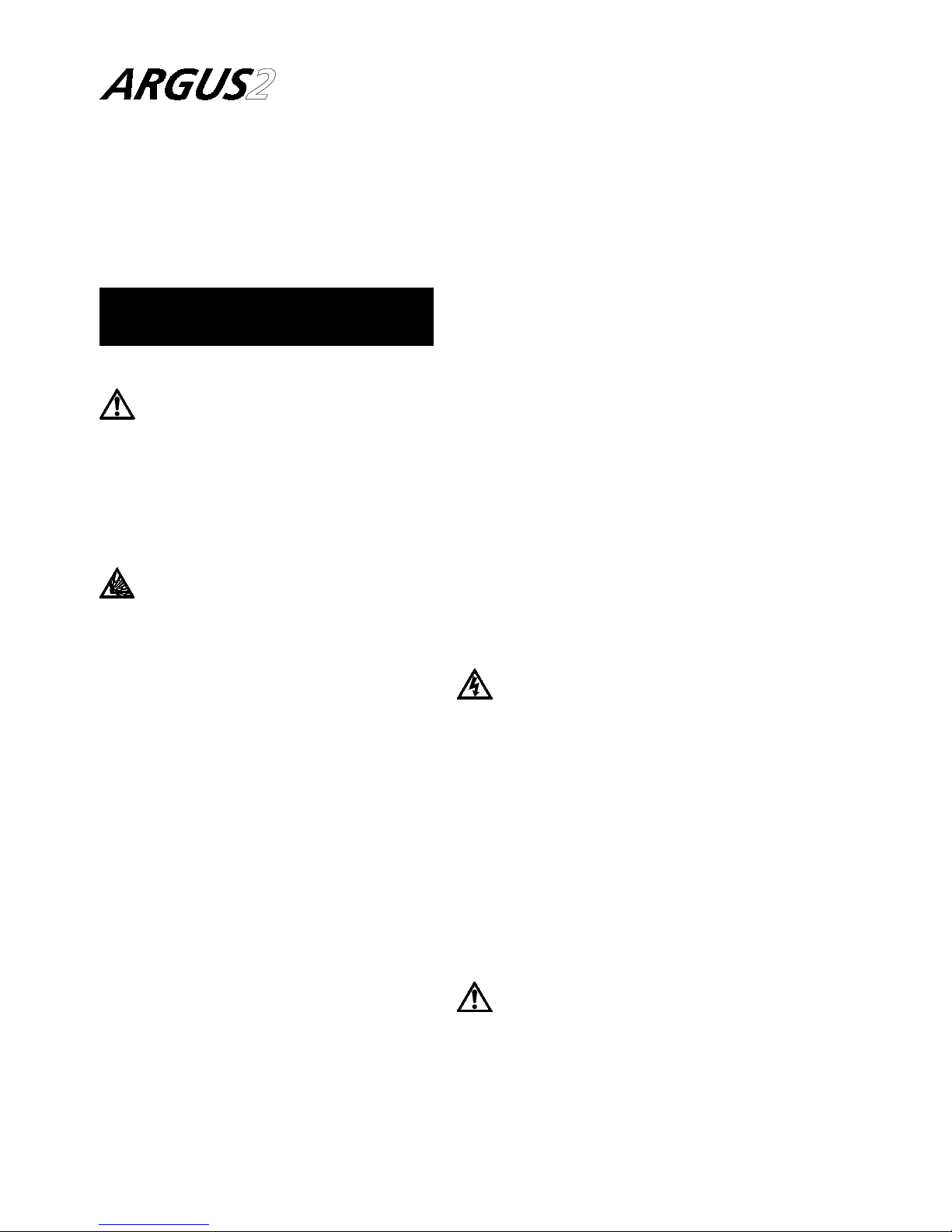
1.1.3 Turn on the unit using the
switch on the rear. This will
latch in and illuminate a red
light in the centre.
1.1.4 From two seconds after switch
on the camera will display the
Argus 2 start up screen while
the system performs a self-test
routine.
1.1.5 After 20 to 40 seconds
(depending on ambient
temperature) the thermal
image, with battery status
display in lower left hand
corner, will appear.
5
1.2 BATTERIES
1.2.1 Recommended Batteries
&
AA Size The most widely
available battery.
&
Type LR6 This is essential to
achieve the specified
battery life. LR6
indicates an alkaline
manganese battery
which can supply the
power requirements
of the Argus 2. Labels
such as ‘long life’ or
‘super power’ are
manufacturers’ titles
and do not necessarily
imply LR6.
&
Change all 8 All batteries in a set
must be changed
simultaneously.
$
Disposal Batteries should be
disposed of in line
with their
manufacturers’
instructions.
Note: Rechargeable packs and
charger unit are availab le as an option
to primary cell operation.
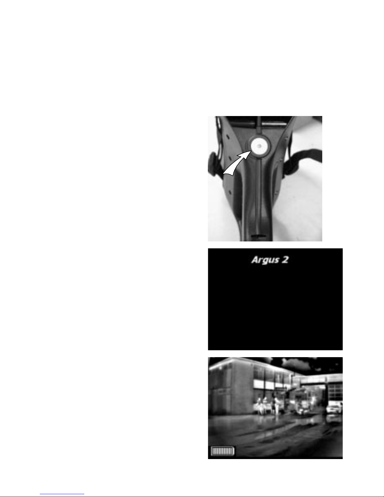
1.2.2 Battery Changing
1.2.2.1 Open the cartridge by
pressing down on the contact end
while holding the outer. The inner will
slip out of the sleeve.
1.2.2.2 Remove the old batteries and
dispose of them safely.
1.2.2.3 Insert new batteries in the
orientation shown on the inner carrier.
1.2.2.4 In order to verify the pack is
ready for use it may be tried in the
camera. A fully charged battery will
show the status display as full (see
below).
6

1.2.3 Battery Indicator
1.2.3.1 The battery pack will power
the camera for typically two hours. It is
recommended that before each BA
team enters the fire the battery pack is
fitted with new batteries (or a fully
charged rechargeable battery).
Note: The operating life of LR6
batteries varies greatly between
manufacturers and is temperature
dependent. Marconi Applied
Technologies recommend the use of
rechargeable systems at ambient
temperatures of 5 8C or less.
1.2.3.2 With a new set of batteries,
the battery bar will be at its full status
with 15 bars showing. With high
quality batteries it may remain at this
height for some minutes. The number
of bars will then progressively decrease
as the batteries are consumed. When
the battery is low, the whole battery
display will flash slowly to alert the
operator. The time remaining will
depend on the type of batteries being
used but will typically be 10 minutes.
EMPTY FULL
15 BARS
7

1.3 DISPLAY GRAPHICS
The Argus 2 camera is equipped with
an advanced microprocessor based
control and user warning system. In
addition to controlling the automatic
operation of the camera to ensure the
best possible picture at all times, the
control system provides graphics on
the display to alert the user to certain
conditions as follows:
1.3.1 Battery Status
The battery status indicator is always
visible at the lower left side of the
display, except during the start up/self
test routine. See section 1.2.3.2 for
details.
1.3.2 Over-temperature Warning
As the circuitry within the camera
approaches its maximum designed
operating temperature, a warning
symbol in the shape of a thermometer
will appear to the right of the battery
status indicator. The camera will
continue to operate at this
temperature but the user may see
some degradation of the image
quality. If the user ignores this warning
and continues to operate the camera
in very high temperatures, the
temperature warning graphic will
flash.
When the temperature warning is
flashing, the camera is very close to
its absolute operating limit and the
image will start to degrade
considerably. The user must remove
the unit from the high ambient
temperature at this time; failure to
comply may result in permanent
damage to the unit.
1.3.3 General System Failure
Warning
As part of the operation of the system,
the microprocessor monitors certain
functions and displays an
internationally recognised warning
symbol if it detects a fault. The
warning, which takes the form of an
exclamation mark within a triangle,
will appear to the right of the battery
status indicator (and to the right of the
temperature warning if this is active).
The warning will appear if any of the
following faults are detected.
8

1.3.3.1 High humidity within the
sealed case assembly. This will occur if
the plastics or the case seal are
damaged and allowing moisture into
the camera.
1.3.3.2 Failure of the lens iris assembly
This warning symbol may appear
briefly during normal operation, but
the camera must be returned to an
authorised service centre or the factory
if the warning symbol remains on.
Failure to act upon this level of
warning may result in serious
damage to the system and may
invalidate the warranty.
1.4 OPERATING NOTES
1.4.1 Interpreting The Image -
Relative Temperatures
The image displayed is simply a black
and white picture of the infra red
energy entering the lens. The camera
displays relative temperature
differences between individual objects
and their surroun dings irrespective of
overall ambient temperature.
The camera is set up to display objects
at various shades between black for
cooler items to white for hotter
bodies, i.e. in a room at 20 8C a cold
drink would appear black whilst a hot
radiator would appear white. In a
room at 250 8C, however, it is possible
that the same hot radiator may appear
darker than for example, burning
materials.
9

1.4.2 Identification of Fire and
Hotspots
The camera will represent zones of
very high temperature as white zones
within the picture. Very small fires or
smouldering material will cause the
automatic iris to close down slightly
but the image of surrounding objects
will remain clearly visible.
1.4.3 Hidden Fires
It is possible that fires may be burning
or smouldering behind doors, in
ducting or indeed in wall or floor
cavities. In such circumstances the
operator should look for areas which
appear whiter when compared to the
surroundings. For example, a fire
behind a door will cause the door to
appear more white against the
background. Similarly, a white area on
an otherwise dark wall could indicate
the area of fire behind the masonry.
1.4.4 Search for Persons and Objects
The camera is not restricted to locating
fires. In many cases the firefighter will
be using the camera in a search for
casualties, to seek out dangerous
items such as fuel tanks or gas
cylinders and also as an aid to
navigation through unknown
premises.
1.4.5 Image Clarity
The sharpness and clarity of the image
provided is related to the temperature
of the scene and objects in view. A
cold room provid es little infra red
energy and less detail is detected than
in a warm environment where objects
give off significant energy. In general
the warmer the scene, the more
thermal contrast and hence greater
detail in the picture.
1.4.6 Heat Layers in Closed Spaces
In a major fire, a layer of hot gases
may build up in the upper region of
the closed space. Attempting to use
the camera in this hot layer will cause
10

the image to become featureless. By
bringing the camera down beneath
this layer the unit is able to provide the
firefighter with a clearer picture of the
scene ahead.
1.4.7 Windows and Polished
Surfaces
Glass is not transparent to long
wavelength infrared energy and it is
not possible for the operator to use
the camera to look through a window.
A white window would indicate that
the window itself is relatively warm
and may be being heated by a fire
behind it. Just as we see reflections in
glass under normal circumstances, it is
possible that the camera can detect
infrared reflections in glass, mirrors
and polished or painted surfaces. Care
must be taken to ensure that the
image seen is not simply a reflection.
Experience will give the operator
added confidence.
1.4.8 Control of Water Streams/jets
When viewed through the ARGUS
camera, water streams from hose reels
will appear black against the
background scene. The control and
aim of water flow can be monitored
by viewing the flow and its effect on
the fire through the camera. It may be
necessary, if employing a water wall,
to drop the wall momentarily to view
the effects of the extinguishing
stream.
1.4.9 Smoke Types
The ARGUS will provide vision through
all types of smoke and steam.
1.4.10 Lens Cleaning During
Operation
The came ra lens, like the BA visor, may
become obscured during use. The lens
may be cleaned with a glove or cloth if
necessary.
11

1.5 CLEANING and MAINTENANCE
1.5.1 Cleaning
After use and prior to stowing, the
camera should be cleaned. This is best
carried out using a cloth soaked with
warm soapy water.
Solvents should not be used. If in
doubt please contact your supplier.
1.5.2 Simple Fault Finding
If you are experiencing problems with
your ARGUS camera then please
follow the fault-finding flow diagram.
1.5.3 User Maintenance and
Replaceable Parts
No routine maintenance is required for
the camera. If it is not in regular use it
should be switched on for a period of
ten minutes every month to check
correct operation.
Due to the environment in which
the camera is used certain parts can
be replaced by the user. These and
the codes by which they should be
ordered are as shown on the
diagram below. THERE ARE NO
OTHER USER SERVICEABLE PARTS.
1.5.4
1.5.5
1.5.6
1.5.7
1.5.8
12

INSERT BATTERY PACK
SWITCH ON
IS SWITCH
ILLUMINATED?
HAS
STARTUP
SCREEN
APPEARED?
IS A PICTURE
PRESENT AFTER
30 SECONDS?
IS THERE
A CLEAR THERMAL
PICTURE?
RESUME NORMAL
OPERATION
WIPE CLEAN
IS
LENS
COVERED
WITH SOOT,
CONDENSATION
OR OTHER
CONTAMINANTS?
REPLACE COMPLETE SET
OF BATTERIES WITH
LR6 TYPE
TRY A NEW
BATTERY PACK
HAVE
BATTERIES
ALREADY BEEN
REPLACED?
HAVE YOU TRIED
ANOTHER BATTERY
PACK?
RETURN CAMERA TO THE
SERVICE CENTRE
YES
YES
YES
YES
YES
YES
YES
NO
NO
NO
NO NO
NO
NO
FAULT-FINDING FLOW DIAGRAM
13

Reference numbers refer to the
sections below on how to fit these
parts.
If any damage beyond these parts
occurs please return the camera to
Marconi Applied Technologies or an
authorised repair centre. Any attempt
at repair by unauthorised personnel
may cause serious damage and will
invalidate the warranty.
1.5.4 Sidestraps (DAS532948AA)
These are retained by two screws on
each side. Once these screws are
undone the straps may be lifted off.
The replacement pair contains all new
parts required. The old strap and
screws can be discarded. Replacement
is the reverse of removal.
1.5.5 Heat Insulating Muff
(DAS532951BA)
This is supplied as one piece including
insulation and BNC cover. Also
included in the kit is the secondary lens
seal.
First remove the sidestraps as per
1.5.4. The muff can be spread at the
rear and pulled forward and upward
off the main camera.
If required the secondary lens seal can
now be replaced. This simply pulls off
the camera. To replace, align the tabs
with the slots in the main casing and
press home, moving progressively
round the lens.
Replacement of the heat insulating
muff is simply the reverse of removal.
Note: Cameras fitted with
temperature measurement require a
different outer cover with holes for the
sensors (DAS548088AA).
1.5.6 Neckstrap (DAS532982AA)
This is removed simply by undoing the
karabiner attaching it to the camera. If
any part of the neckstrap is damaged
it should be replaced as a complete
assembly.
14

1.5.7 Visor (DPP532448AA)
This flexible part clips tightly over a
flange at the rear of the camera. It is
removed by pulling backward the
material near the flange. The visor will
detach from the camera. To fit the new
part place the cutout on the visor over
the flange at the top of the camera,
pull it over one top corner. Now pull
the visor over firstly the second top
corner and then the two lower
corners.
1.5.8 Battery Pack (DAS532398AA)
Spare primary cell packs are available.
15

1.6 SPECIFICATION
Dimensions .......... 30x29x12cm(WxHxD)nominal
Weight ............ 2.2kgnominal (excluding batteries)
Power supply ......... 8primary batteries type LR6 or NiMH
rechargeable pack
Power consumption ........... 4.5Wnomi nal (dependent
on ambient temperature)
Battery status indicator ................Onscreen
Battery life ................. 120minutes typical
continuous operation
Field of view .............. Bi-ocular, 508 horizontal
Visor ....................Adapted to masks
Optics ..............Germanium lens f/1.0 for infrared,
8to14mm, automatic aperture
Carrying mode ....... Inreadiness by neckstrap. In use by grip or
adjustable sidestrap
Operation .............Onebutton with indicator light
Depth of field ................Onetothirty metr es
Visual performance ...... Visibility is not impaired by smoke, water
vapour, water spray or darkness but is
obstructed by stone, glass, snow, ice and
most plastics. An image builds up when
surfaces have a temperature difference of
greater than 0.1 8C.
16

Objects with increasing
temperature ............Themore an object is heated the
brighter its image, i.e. a man near
a fire appears darker than the fire.
High temperature tolerance ..... Thecamera is designed to have a
temperature tolerance greater
than that of the firefighter, e.g.
80 8C maximum one hour
150 8C maximum 15 minutes
See also section 1.3.2.
Low operating temperature ...... Normal batteries minimum 5 8C
Rechargeable batteries 710 8C
Storage temperature ............... 710 to +50 8C
Sealing .............Dust and water proof to EN 60529,
class IP67
EMC.................. Asdirective 89/336/EEC
Mechanical stability ........ Tested against shock and vibration
Video output ........ Connector for BNC plug (sealed by rubber
cap). Connection cable 75 O coaxial for
recorder or monitor. The unit will support
up to 100 metres of video cable.
Storage .............
Carrying case for camera, neckstrap,
spare battery pack and user manual
Service ........Periodic service is not required. High temperature
insulation, visor and sidestrap exchangeable by
user. Repairs must only be made by the
manufacturer or authorised local service centre.
17

1.7
TEMPERATURE MEASUREMENT
(Optional, designated as /TP)
The addition of two sensors to the
Argus 2 camera allows the operator to
view the average scene temperature
(within a defined area) and the
ambient air temperature. The
temperatures are displayed as an
overlay on the camera video at the
bottom right hand side of the picture.
This system is intended to give the
operator the ability to detect possible
hazards such as hot gas bottles or
tanks and a warning of high air
temperatures.
1.7.1 Spot Temperatur e
&
.
Measurement is by means of a
pyrometer mounted inside the camera
case and viewing the scene through an
aperture in the outer cover. The sensor
is protected from heat and moisture as
are the other camera electronics. The
sensor displays the average scene
temperature within the sample
window, which appears as a digital
readout at the bottom of the display.
The camera can be configured to give
a reading in degrees C or degrees F,
specified at time of ordering.
SPOT SENSOR AMBIENT SENSOR
"
"
SAMPLE
WINDOW
SPOT
TEMP
AMBIENT
TEMP
"
18

Scene temperatures between 0 8C
(32 8F) and 500 8C (932 8F) can be
displayed. If the temperature lies
outside this range a 4 or 5 symbol
appears before the reading indicating
that it is outside the possible range.
Note that if the object in the scene
does not fully fill the sample window
then a false reading may be obtained.
Care should be taken not to cover up
the sensor window (with a hand for
example) when using this system.
1.7.2 Ambient Temperature
&
The ambient temperature sensor plugs
into the RS 232 computer test point
on the front of the camera and the
ambient temperature is displayed on
the video as for the scene temperature
above. The range for ambient
temperature measurement is 0 8C
(32 8F) to 150 8C (302 8 F). If ambient
temperature measurement is not
required the sensor can be unplugged
and the readout display will
automatically be removed from the
video.
Specification
Range . . spot/scene temperature
0 8C to 500 8C
(32 8F to 932 8F)
Ambient .... 08C to 150 8C
(32 8F to 302 8F)
Accuracy:
spot (see note) . +2 8Cor+ 2%
(whichever is the greater)
ambient ....+2 8Cor+ 5%
(whichever is the greater)
Power consumption . . negligible
This option has no
significant effect on
the battery life of
the camera.
Note the sensor assumes that the
object in the scene has an emissivity of
0.95. The readings may be inaccurate
when viewing shiny metal or glass
objects.
19

2 Charger and Batteries
2.1 GETTING STARTED:
Connecting Power to the
Charger
The charger is powered from the AC
mains supply. When powered with no
pack inserted, the STATUS indicator
will show green. The charger may be
left powered continuously.
2.1.1 To Power from an AC Supply
Connect the AC supply lead to the AC
mains input socket on the rear panel
of the charger (see below).
Connect the AC supply lead to a mains
supply of the voltage specified on the
rear panel.
CAUTION
Charger type DAS546180AA is for
operation on 100/120 V, 60 Hz mains
supplies.
Charger type DAS546180BA is for
operation on 200/240 V, 50 Hz mains
supplies.
AC INPUT
"
20

2.2 OPERATION of the CHARGER
2.2.1 Indicator Description
STATUS
GREEN ............. ready for use
RED............packisoutside normal
operating temperature range
DISCHARGING YELLOW ..... anyremaining charge in the pack
is removed to allow optimum recharge
CHARGING YELLOW ...........pack under charge;
progress indicated by bargraph
CHARGED GREEN ...... pack has completed fast charge
and entered trickle charge mode
The bargraph indicator to the left of the pack entry slot shows the charge state
of the pack.
Note: Packs should only be inserted
into the charger when the STATUS
indicator is green and all other
indicators are unlit. This may be up to
30 seconds after the removal of the
previous pack.
STATUS INDICATOR
DISCHARGING
INDICATOR CHARGING INDICATOR
CHARGED INDICATOR
CHARGE BARGRAPH
PACK SLOT
DISCHARGE BUTTON
"
"
"
"
"
"
"
21

2.2.2 Operation (Normal)
Connect power to the charger as
described in section 2.1.1. Wait for the
STATUS indicator to show green. Insert
a pack into the front panel slot,
contact end first. The CHARGING
indicator will illuminate showing the
charger has entered the fast-charge
mode. The charge bargraph will
indicate the amount of charge
present.
When the fast-charge mode is
completed the CHARGING indicator
will extinguish and the CHARGED
indicator will illuminate, showing the
trickle charge mode has started. This
mode will top up the battery to full
capacity.
The charge bargraph will indicate
100% when the pack is fully charged.
A pack may be removed from the
charger at any time. The available
charge will be proportional to that
indicated on the charge bargraph.
It is recommended that the packs are
left in the charger for 2 hours after the
CHARGED light has illuminated, to
allow them to achieve full charge
capacity. A pack may safely be left in
the powered charger indefinitely.
CAUTION Do not leave a pack
in the charger with no power applied
for long periods; this may deeply
discharge the pack and cause loss of
cell capacity.
2.2.3 Operation (Discharge before
Charge)
(For pack electronics re-calibration)
Connect power to the charger as
described in section 2.1.1. Wait for the
STATUS indicator to show green.
Depress the DISCHARGE button before
inserting the pack. The DISCHARGING
indicator will illuminate showing the
charger has entered the discharge
mode. Release the DISCHARGE
button. The charge bargraph will show
the amount of charge present.
When the pack has been discharged
the charger will switch automatically
to fast charge mode. Operation will
then be as described in section 2.2.2
above.
22

2.3 ADDITIONAL OPERATING
NOTES
2.3.1 Conditioning New Packs or
Packs from Storage
New packs and packs which have been
unused for several weeks may be in a
state of deep discharge. In this state
upon charging, the CHARGED
indicator will illuminate before the
bargraph shows 90%. The pack will
need conditioning as follows:
1) Remove the pack from the
charger. When the CHARGED indicator
extinguishes, re-insert the pack into
the charger. The charger will enter the
fast-charge mode.
2) If the CHARGED indicator
illuminates with less than 90%
indicated on the charge bargraph,
leave the pack in the charger for at
least two hours then remove the pack
from the charger. When the CHARGED
indicator extinguishes, re-insert the
pack into the charger. The pack should
now fast charge to 100% as normal.
Note: In extreme cases it may be
necessary to repeat the conditioning.
2.3.2 Shelf Life
The pack self-discharge consumes up
to 2% of full charge per day. Packs
stored off-charge will still run a camera
for 1 hour after two weeks storage.
The charger’s mai ntenance mode
ensures that packs remain fully charged.
It is recommended that packs are stored
on charge, or routinely charged-up.
The shelf life of charged packs is
maximised by storage between
10 and 25 8C.
2.3.3 Memory Effects
The charger is designed to counteract
‘memory’ effects in the pack by using
a pulse charging system to condition
the pack while charging. There is no
need for a regular dischargebefore-charge routine. The discharge
before charge function is intended for
occasional use to recalibrate the inpack intelligence (see section 2.3.5).
23

2.3.4 Temperature Range for
Charging
If the temperature is below 10 8C, the
charger will automatically reduce the
rate of charge to avoid cell damage;
the STATUS indicator will show red,
the CHARGING indicator will
illuminate and charging will continue
at the lower rate. Normal fast charging
will automatically resume when the
pack temperature exceeds 10 8C.
When using the discharge before
charge mode below 10 8C, the fast
charging mode is not entered until the
pack temperature exceeds 10 8C.
The charger has a safety cut-out,
which will operate if the pack
temperature rises above 45 8C. In this
case the charger will not charge and
the STATUS indicator will show red. No
indicators or functions operate in this
state. The pack should be removed
and the charger power supply
momentarily disconnected to reset it.
2.3.5 Re-calibrating the ‘In-pack
Intelligence’
In normal use the ‘in-pack intelligence’
automatically re-calibrates the full
capacity of the pack whenever it
receives a full discharge.
If the battery pack is often used for
short periods and never fully
discharged the accuracy of the battery
status display in the camera will
reduce.
If it is suspected that there is any
inaccuracy in the bargraph display, recalibrate the pack by using the
discharge before charge function as
described in section 2.2.3.
It is recommended that this procedure
is carried out on each pack at least
once per month, to re-calibrate the
pack electronics.
Note: A reduced charge capacity may
have arisen as a consequence of
ageing or damage within the pack.
24

2.3.6 Normal Indications
Other indications may appear briefly as the charger changes between these
states.
6
= INDICATOR OFF
*
STATUS
6
DISCHARGING
6
CHARGING
6
CHARGED
*
STATUS
*
DISCHARGING
6
CHARGING
6
CHARGED
*
STATUS
6
DISCHARGING
*
CHARGING
6
CHARGED
*
STATUS
6
DISCHARGING
6
CHARGING
*
CHARGED
The charger is ready to accept a battery pack.
The charger is discharging the pack.
The charger is charging the pack.
The charger has completed the fast charge and
entered trickle charge mode.
25

2.3.7 Other Indications
*
STATUS
6
DISCHARGING
6
CHARGING
6
CHARGED
*
STATUS
6
DISCHARGING
6
CHARGING
6
CHARGED
*
STATUS
*
DISCHARGING
6
CHARGING
6
CHARGED
*
STATUS
6
DISCHARGING
*
CHARGING
6
CHARGED
*
STATUS
6
DISCHARGING
6
CHARGING
*
CHARGED
(No battery pack inserted)
The charger is outside the normal charging
temperature range.
(Battery pack present)
The charger/pack is too hot. Remove pack and
disconnect power until the charger/pack has
cooled down. The bargraph reading is not
accurate in this state.
The charger is discharging the pack and it is cold.
The charger is charging the pack slowly because it
is cold.
(Full bargraph) The charger has charged the pack
and it is cold.
(Empty bargraph) The charger has discharged the
pack but it is too cold to charge. Normal charging
resumes when the temperature is within limits.
26

2.4 PROBLEM SOLVING
Problem Cause Action
No indicators lit No power Check connections and fuses. If
the problem persists return the
charger to the supplier
Only green
STATUS light
when pack
inserted
Pack not
connected
Remove and reinsert the pack.
If the problem persists return
the pack to the supplier
CHARGED state
reached without
full battery
indication
Pack was in deep
discharge state
Condition the pack as
described in section 2.3.1. If
unsuccessful, recalibrate the
pack as described in section
2.3.5
Peak charge
indication
appears
inaccurate
In-pack
Intelligence
requires
recalibration
Recalibrate the pack as
described in section 2.3.5
27

2.5 SPECIFICATIONS
2.5.1 Charger (DAS546180AA or BA)
Description ........Fastcharger for one ARGUS
Rechargeable Pack.
Power requirements:
DAS546180AA ......100to120VAC,60Hz,40Wmax
DAS546180BA ......200to240Vac,50Hz,40Wmax
Width .........180mmnominal
Height (including feet) ....60mmnominal
Depth ..........170mmnominal
Net weight ........1.5kgnominal
Temperature (operating) ....0to+408C
Environmental sealing ....IP20
Electromagnetic compatibility . . EMC Directive 89/336/EEC
Safety ..........LowVoltage Directive 73/23/EEC,
BSEN60335 Part 1 and Part 2-29
For operation from a DC supply, the use of an appropriate DC to AC adaptor is
recommended. Contact Marconi Applied Technologies for details if required.
28

2.5.2 PACK (DAS533206DA)
Description: ........Arechargeable Ni-MH pack for use
only with the Argus or Argus 2
Camera. The pack contains charge
management circuitry to indicate
charge status to the camera, and
has recoverable short-circuit
protection.
Capacity .........8Ni-MH cells, IEC nominal capacity
1600 mAh
Length .........129mmnominal
Width .........36mmnominal
Height .........38mmnominal
Net weight ........250gnominal
Temperature:
storage ........710 to +40 8C
operating ........710 to +40 8C
710 to +65 8C (can be tolerated
for short periods)
Environmental sealing ....IP55
29

3 Warranty Terms
3.1 EXPRESS WARRANTY
Marconi Applied Technologies
("Marconi") warrants that this product
is free from mechanical defects or
faulty workmanship for two (2) years
from the date of shipment, with the
exception that the warranty period for
the battery charger is one (1) year and
for the rechargeable battery pack is six
(6) months from that date , provided it
is maintained and used in accordance
with Marconi’s instructions and/or
recommendations. This warranty does
not apply to expendable or
consumable parts whose normal life
expectancy is less than one (1) year.
Replacement parts and repairs are
warranted for ninety (90) days from
the date of shipment.
Marconi shall be released from all
obligations under this warranty in the
event repairs or modifications are
made by persons other than its own or
authorized service personnel or if the
warranty claim results from misuse of
the product. No agent, employee or
representative of Marconi may bind
Marconi to any affirmation,
representation or modification of this
warranty concerning the goods sold
under this contract.
THIS WARRANTY IS IN LIEU OF ALL
OTHER WARRANTIES, EXPRESS,
IMPLIED OR STATUTORY, AND IS
STRICTLY LIMITED TO THE TERMS
HEREOF. MARCONI SPECIFICALLY
DISCLAIMS ANY WARRANTY OF
MERCHANTABILITY OR OF FITNESS
FOR A PARTICULAR PURPOSE.
30

3.2 EXCLUSIVE REMEDY
It is expressly agreed that the
Purchaser’s sole and exclusive remedy
for breach of the above warranty, for
any tortious conduct of Marconi, or
for any other cause of action, shall be
the repair and/or replacement, at
Marconi’s option, of any equipment or
parts thereof, that after examination
by Marconi are proven to be defective.
Replacement equipment and/or parts
will be provided at no cost to the
purchaser, F.O.B. Marconi’s plant.
Failure of Marconi to successfully
repair any non-conforming product
shall not cause the remedy established
hereby to fail of its essential purpose.
3.3 EXCLUSION OF
CONSEQUENTIAL DAMAGES
EXCLUSION OF CONSEQUENTIAL
DAMAGES – PURCHASER
SPECIFICALLY UNDERSTANDS AND
AGREES THAT UNDER NO
CIRCUMSTANCES WILL MARCONI
BE LIABLE TO PURCHASER FOR
ECONOMIC, SPECIAL, INCIDENTAL
OR CONSEQUENTIAL DAMAGES
OR LOSSES OF ANY KIND
WHATSOEVER INCLUDING, BUT
NOT LIMITED TO, LOSS OF
ANTICIPATED PROFITS AND ANY
OTHER LOSS CAUSED BY REASON
OF THE NON-OPERATION OF THE
GOODS. THIS EXCLUSION IS
APPLICABLE TO CLAIMS FOR
BREACH OF WARRANTY, TORTIOUS
CONDUCT OR ANY OTHER CAUSE
OF ACTION AGAINST MARCONI.
31

In the event of a warranty failure, please return your camera to your local Argus
sales centre:
USA
The argusdirect team
Marconi Applied Technologies
4 Westchester Plaza
Elmsford
NY 10523-1482
Tel (Toll Free): 1 888 587 0103
Fax: (914) 592 5148
E-Mail: argus.direct@marconi.com
France
Philippe Silvestre
Marconi Applied Technologies
16 Burospace
91572 Bievres
Cedex
Tel: 01 60 19 55 80
Fax: 01 60 19 55 29
E-Mail: mtech.fr@marconi.com
Web site: www.argusdirect.com
Canada
David Soward
Marconi Applied Technologies
7956 Torbram Road
Suite No. 208
Brampton
Ontario L6T 5A2
Tel: (905)789 3840
Fax: (905)789 3847
E-Mail: david_soward@eevinc.com
UK & Rest of the World
Andre Goodson / The argusdirect team
Marconi Applied Technologies
106 Waterhouse Lane
Chelmsford
Essex CM1 2QU
England
Tel: +44 01245 453501
Fax: +44 01245 453703
E-Mail: andre.goodson@marconi.com
Printed in England
32
 Loading...