


Marconi TF 2603 Operator Manual
mallconl
tnstruments
NI§"
MILL
IVOLTMETER
lnstruction
Manual
Instruction
H
52603-304P
2nd
Edition
Manual
RF Electronic
TF
code Nos.
2603
Millivoltmeter
,rUOr_3311
ocr.
79
(am.
:)
@
977
MARCONI INSTRUMENTS
ST. ALBANS HERTFORDSHIRE
prinr
code
D_to/79,
LIMITED
ENGLAND
Mr
2.0c
Pr
e1
Page
im.
I

CONTENTS
PRELIMINARIES
H
52603-304P
Title
Cont ent s
Notes
CHAPTERS
I
page
and cautions
General
information
2 Operation
3 Technical description
4 Maintenance
(not
5
assigned)
6 Replaceable parts
7 Circuit
diagram
Note
Each
date
mnterial
indicated
the change.
Any
included on
Prelim.
Page 2
. ..
page
bears the date of
of the latest
of technical
by triangles
changes subsequent
inserted sheets coded
amendment
importance
positioned
trIhen a chapter
to the latest amendment state
the original
(en.
I
,
introduced
thus
issue or the code
2
Am.
)
etc.
by
).
the
(
latest amendment
to show the extent of
is reissued the trrangles
Cl, C2 etc.
number and
New or
amended
do not appear.
of the manual
is
are
Sep. 77

H
52603-304P
ELECTRICAL
SAFETY
This equipment is
designed
Measuring
cautions
ment
Defects
damage
inoperative
Removal
have
and tested
Apparatusr,
must
in a safe
and
abnormal stresses
trrrhenever
caused
and
of
covers
Removal
been
of
taken in the
be observed
condition.
it is like1y
by severe
secured
be
the covers is 1ike1y
shall be disconnected
maintenance
maintenance
skilled person
Note
has
been disconnected
ment,
mains
the
capacitors
filter
mains
and repair
or repair under
who is
that capacitors
connected
capacitors,
plug.
NOTES
PRECAUTIONS
protected
according
and
has
by the user to ensure
that
conditions of
against any
design
of the equipment
from the
during
which the equipment
voltage
aware of
inside
from
the supply.
to
high
if fitted,
AND CAUTIONS
in
accordance
to IEC
been supplied
Publication
protection
transport
unintended
to
expose Live
supply
before carrying
is inevitabl-e
the hazard
invol-ved.
the equipment
Before
voltage
short
together
with IEC
348,
in a safe
safe
has
been
or storage,
to shield
may stil"L
carrying
points
Safety
tSafety
Ctass l. It
Requirements
condition.
operation
impaired,
and to
for example
the equipment
operation.
part.s
although
parts.
such
out any adjustment,
sha11
it
shall only
opened.
be
be carried out
be charged
out any work
should
the L
discharged;
be
(live)
and N
has beeo
for Electronic
The following
retain
as a
shal1
reasonabl-e precautions
The equipment
replacement or
pre-
the equip-
resul-t
be made
of
If any adjustment,
by a
when the
equipment
inside the equip-
to discharge
(neutral)
pins
of
Mains plug
The mains plug
earth
lead
or
Fuse.:s
contact. The protective
without
ou.tside
Note that
protective
the equipment
supply 1ead.
possible
be
orientation
instrument
To
filter
used
be
Make
are
used for replacement.
holders
RADIO FREOUENCY INTERFERENCE
>
This
of
r.f.
for
of the
could remain at supply
provide
where fitted,
in
the live 1ead. The fuse
sure that
sha11
be avoided.
equiprnent
interference.
shall
the supply fuse
If
equipment is
the
the fuse to
plug
in its socket. In
protection
an external
only fuses with the required
conforns with
only be inserted
action
conductor.
is likely
is
become
shall not
Any interruption
make
to
connected
connected
connectäd
potential
against
breakdovrn
supply fuse
should have a continuous
The use of mended
the
requiremeots
in a
socket outlet
be negated by the
of the
provided
protective
the equipment dangerous.
in
series with
to the
to
supply
the neutraL side depending
these circumstances
even
after
the fuse has ruptured.
of the supply
(e.g.
fitted
brown
the
via a two-pin
certain
1ead, its connectors, and
in the
rating not
rated current
fuses and
the short-circuiting of fuse
and of
of EEC Directive 761889 as co
with a
use
of an
conductor
(live)
plug,
parts
connecting
exceeding
the specified
protective
extension
of the
wire
it
upon the
of the
pl,ug)
limits
inside
will
should
6 A.
type
Feb.
79
(em.
2)
Prel
Page
im.
314

Chapter I
H
52603-304P
GENERAL
Para.
I Introduction
Performance data
4
I 3 Accessories
Fig.
I RI' Electronic l"li1livo1tmeter TF
I.NTRODUCTION
l. The
ing the
deflections from
2. Meter
when
changes,
using the
a sine wave)
giving
detection
single
diode
2603
TF
frequency range
a highly
is
I
mV to
sensitive,
kHz to
50
3
V, enable voltages down to 300
readings are very close to true r.m.s. values up to 30 mV,
100:l multiplier;
and approaches a
on the higher ranges. The
an
effective range
peak-to-peak
of
0 to 7l dB with respect to 3.162
of the input signal by the
probes.
INFORIVIATION
CONTENTS
2603
general purpose
1500
MHz;
above this value the response
reading
eight
(calibrated
rnillivoltmeter,
ranges,
giving
uV
in r.m.s. value of
to be measured.
meter is also calibrated in
V. Fu1l wave
probe
minimizes
errors
associated
Page
I
cover-
full-scale
or 3 V
gradually
decibels
with
3. The voltmeter roay be operated
from mains or battery supplies.
versions of the voltmeter are available, differing only in the
accessories
supplied.
'lt.r 1
It\
'llt
r\
t
Two
range of
Sep.77
Fig. 1
RF ELectronic
Milliuoltmeter TF
2603
Chap.
Page
I
I
H
52603-304E
PERT'ORMANCE
4.
voltage
DATA
range I
5. Frequency
6.
Accuracy
@mfroC
7.
Frequency
(I,rlhen
coaxial
TYL 7948
nated
firted
T Connector
and termi- 200
with
Notes...
(l)
The instrument
to 50 MHz, and the error over this
range
28oC)
ro
response
wirtr
50 fz)
will usually be operated
r.m.s.
mv
full-scale
put,
300
50 kHz to
S mV range z
200
I,trith respect
50 kHz
50
500 MIIz ro
900
8
V
l0
mV
and
I mV
range :
kEz to 50 MHz.
Mllz to 200
Wlz to
MHz
deflection in B
V r.m.s.
d.c.
1500
higher
200
to
500
900
to 1500
fu1l-sca1e
Probe
MHz.
deflection,
will withstand
ranges :
!52
of full-scale.
!5%
of futl-sca1e.
200
to
kHz
MHz :
MHz
MHz
range is shown
k[z.
.
+0,
10.4
:
z
MHz :
in
the
-0.4
dB.
11.0
!2.0
t3.0
frequency range
ranges.
!32
of full-scale.
dB.
dB
dB.
dB.
against
to
3 v r.m.s.
Maximum
up to
2O0
Accuracy.
in-
kEz
(2)
I,rlhen using the instrument at other frequencies,
error must be added to the appropriate
overall accuracy.
(3)
Meter scales
B.
Input
9.
Chapter
quency response
2, Fig. 3 shows
impedance
10. Probe
7a
s
/kop/
/eis/ttn3s
t. Power req.uirements
I
6
e/arf
limits.
the
Accuracy
in
detail the
3.162, and 0 to
0 to
Cal ibrated in the r.m. s.
Special
scale
Decibel scale
Range switch in
The dB scale is
Input
Input
Chapter
variation
Uses t\^/o crystal
capacitance
resistance
2,
of input resistance
circuit which
typical spread
I
for
0
Fig. 4 shows in
minimizes
mV range.
I I
ro
l0
dB steps.
not
applicable
:
:
diodes in a full
figure to obrain the
I0
virtually
value of a sine
dB, 0
less than
I
and
greater
I
MHz and
errors
non-sinusoidal waveforms.
ensures
minimum effect. Response
r'm'
that ambient temperature
with inputs
s'
of 30 mV or less'
Frequency response
of the
probe
fre-
linear.
\^/ave.
dB at full-scale.
pF
125
r.m.s.
I
mV range.
I
at
kCI at
MHz
to the
2.5
V r.m.s.
than
I
V
detail the typical
with frequency.
wave detecting
when measuring
A built-in
heater
variations
very close to
is
have
true
Chap.
Page
supply
AC
tilee
hse(s*om
Poqrer
eonsumptiorr
n
/er?trrya.//2?ditn
I
2
ed2
45 Hz to 500 Hz : i90
(a1so
500 Hz to
1000 Hz at
5.4 VA.
€
V
to
265
tlOZ
V or
on
V
95
230
V).
Sep. 78
to
132
(Am.
V
I
)
H
52603-304P
Battery
12.
Dimensions
ACCESSORIES
13.
tr^IiLh
(ll)
are optional.
(l)
version
Mains
and
lead
rVe*Anta42fr4
(2)
Earth prod,
fidAnJsePr'/te
(3)
Earthing
(4)
(5)
Ftatqa
Earth
fta(uo
Printed
6 sb?abrctc/f
J
spring clip
/
supply
weight
52603-304P,
I^rith
n
crr
TM
version
7936
sleeve
,?.lrrflDc
f
wiring plug
20vro32v
Height
204
mm
(8
in)
irems
MI
MI
prod
MI
Aprobe
MI code :
flexible
MI
sockets
(l)
52603-305X
code
code z 44314-602L.
which clips on
code :
at the higher frequencies.
code z 23421-03IK.
floating;
to
: 43129-071D,
33631-901J. Provides
22328-013N.
earth connection'
printed
on
I^Iidth
292
(lll
(7)
items
142
67
mm
in)
are
supplied and
(l)
ro
A
to the
A1lows rhe use
Connects r{ith
boards.
(heater
nA
EA
(heater
on),
off).
Depth
280
mm
(
I
I
in)
irems
(ll)
are all
spring loaded
probe
body.
earthing
test
l{eight
9.8 kg
(22
(8)ro
supplied.
earthing
of the
of a
point
Lb)
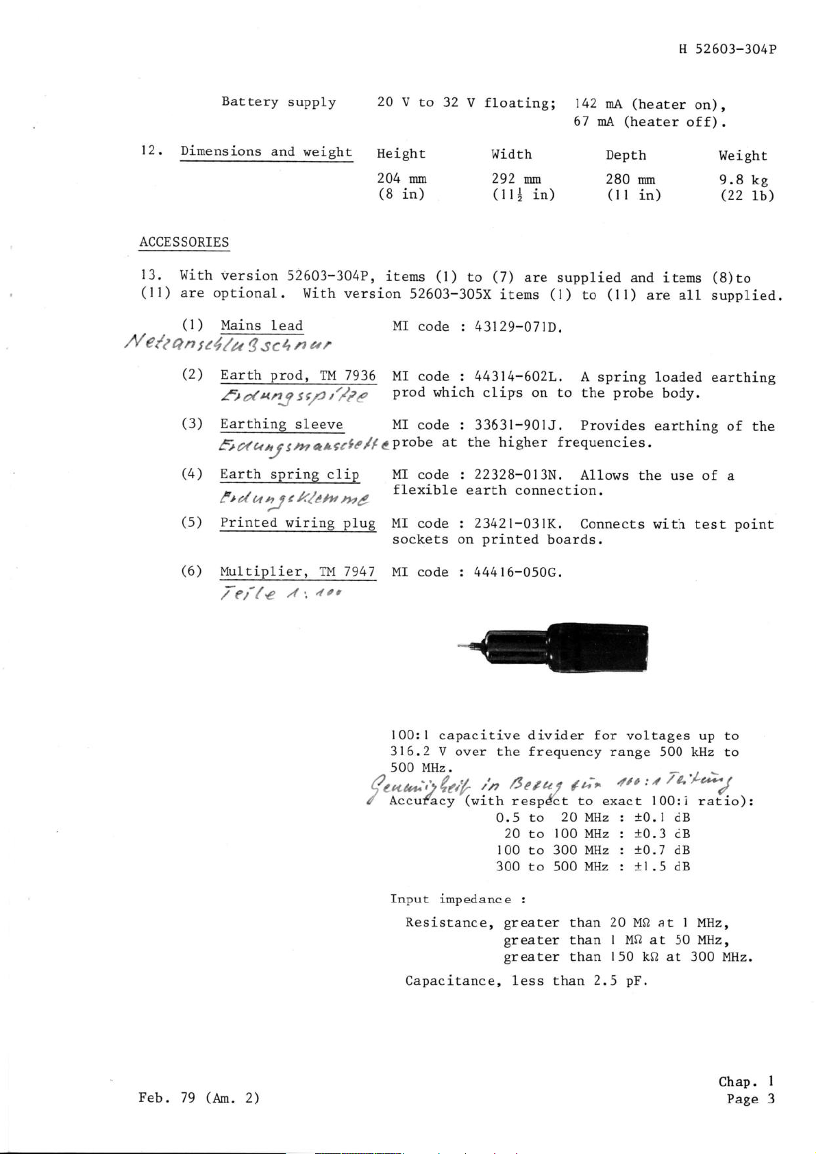
(6)
Multiplier,
'7ei/c
/ f
TM
7947 MI
iot
code : 44416-050c.
100:l
316.2
500 MHz.
4r"i,1/g4
Accufacy
/
capacitive divider for voltages
V over the frequency
,'n
(with
0.5
100
300 to 500 MHz : !1.5 dB
Input
impedance :
Resistance,
Capacitance, less than
/3er4/
(it'
range
4to:/t
500 kHz to
7a'/-&S
respdct to exact 100:i
to
20
100 MHz :
to
300 MHz :
to
greater
greater
greater
20
than
than
than
l{Ilz :
20
I
150
2.5
10.1
t0.3
10.7
M0 at I
M0 at
kf2 at 300 MHz.
pF.
dB
dB
dB
50
up to
ratio):
MHz,
MHz,
Feb.
79
(am.
2)
Chap.
Page
I
3

H
52603-304P
(7)
Accessory
TM 7960
(8)
Coaxial T connector,
Tt't 7
948
case,
Ivlaximum
316.2
Above
input
V up to 100
100
MHz
where f is in MHz.
V d.c. plus
MI code :
MI code :
V
4167 3-015N.
431 67-0072.
:
MHz.
maximum r.m.s.
to6
3 x
f2
a.c. peak
must
voltage
not
exceed
=
1000
v.
(
9)
Adapter
TYt 7949
N terminated,
VSI^IR not
greater
terminated in
in
side
entry.
50
than
0
1.2:
I at 1500 MHz
and voltmeter
when
probe plugged
Accuracy and Frequency response specification
given
Performance
in
Data applies
to voltage
across 50 Q load.
MI code z
A1lows voltage
in 50
Maximum
VSWR
when
maximum
maximum 1.2:1,
431 68-01
fi type
porler
mounted
l. l: l,
N
I
S.
measurement across load
p1ug.
input,
0.25 W.
on voltmeter
50 kHz
500 kHz
to
500
to 900
probe:-
MHz,
MHz.
mounted
Chap.
Page
I
4
Feb.
79
(en.
Z1

H 52603-304P
(10)Adapter N
(l
I
nated,
50
)
TM
fi Load
untermi-
7950
TYt 7967
MI
code : 43168-010V.
0
type N adapter with specification
50
terminated
adapter
but
MI code z 44411-015N.
without
50
as
CI 1oad.
Load
VSLIR
mounted in
greater than
not
type
plug.
N
1.05:1, d.c.
Lo
I
500
MHz.
Feb. 79
(am.
Zi
Chap.
Page
I
5/6

H
52603-304P
Para.
I
Controls and connectors
3 Preparation for use
3
Meter loeation
4 AC
8 Battery
l0
I I Switching
I I
14
l8
21 Operating
21
23 Probe
24 Range
26
28
35
pol4rer
Mechanical
trIarm-up
Balance
Screening
supply
supply
zero
on
period
procedure
Voltage limitations
input impedance
selection
Range switching
Accessory
Use of accessories
selection
49 dB measurements
Applications
5l
Chapter
OPERAT
CONTENTS
2
I
ON
Table
I
Frequency range of accessories
Fig.
I
Controls and connectors
2
Controls and
connectors on
on
front
rear
3 Voltmeter frequency response limits
Probe
4
Insertion
5
CONTROLS AND
l. The
are as follows:-
(l)
Red
and multiplier
input
resistance
loss curve
CONNECTORS
controls and connectors on the front
SUPPLY switch. For
screening is
visible
switching
when
panel
panel
.. 6
on/off
switched
panel
on.
...
of the voltmeter
a.c. or battery supply.
the
(Fig.
Page
8
Page
2
3
9
I
0
l)
Sep. 77
Chap.
Page
2
I

(1)
,t,-_
l3r0Irmu13
l,L,lJ,,l,,lol"
--
\\\)-Ll//
\\X]I\\/,/
\v// \\\-//
(t
\
.\_a
\\\/
A
,/
""*".\l
rrrri"rr"\\
-J-J-/
H
52603-304P
rv
r
y
(2)
to be measured.
(3)
probe
(4)
dB,
2.
The
are as
(5)
being
(6)
Q)
(8)
selected
(9)
190
(10)
the mains
(ll)
supply or
Ftg"
RANGE
BALANCE
warmed up.
switch.
METER.
the
voltage
controls
follows:-
Nolt
MArNS/BATTERy
used.
BATTERY
MAINS
BLANKTNG plate.
6clto,
/
supply
position.
Ll,tcl.5ir4,
AC FUSE.
V
265
to
Ne/z
MAINS
*"\
I
DC FUSE.
Y,
-
lüe'$rulth.
supply
lead-
ct,,
i
rectified
L
Controls
For
selecting
control.
For
For indicating
detected
and
connectors
supply
range
switch.
by the
terminals.
switch.
For
Value
100
determined
mA for
)Tectet
p1ug.
160
mA.
a.c.
supply 1ine.
and conneetors
on
front
the appropriate
adjusting
on
a scale
probe.
on
the rear
Set to
securing
95 V to
For
connecring
Connecred by mains/barrery
meter
position
Selects
rhe mains
by a.c.
t32
V.
to
calibrated in
panel
appropriate
a.c.
supply
supply volrage
rhe a.c. supply
panel
range for
zero
of the
voltage range.
with
zero input
r.m.s.
voltmeter
to
range
:
switch
the voltage
and
values
and
(Fig.
supplies
switch in the
rnA
50
by
Eo barrery
for
means
of
2)
Chap.
Page
2
l?eb.
79
(An.
2)

§)
ffi[[il
H
52603-304P
7a
(12)
.-i;1;/:',r,,r'
(13)
voltage
.taq
i"
5
PREPARATION
t.b'r,
rrr'q
Fta.
t/*op/
PROBE c1ip. For retaining the voltmeter
PROBE.' For connecting
under test.
t,t,
X
,1
FOR
.l:
USE
z
-',lnrtlLa'ci.üi
("r,.itq
Controls
and
direcE or via the accessories,"{o the
Meter location
3. The sensitivity
panel
bottom
that
AC
4.
socket
cut-out. As the meter has
of the
the meter
powe.r
The mains lead is
which
cut-out, it should
has not moved.
supply
connects
of
with
the
meter
is affected by its
been calibrated
be verified, on
a free cable fitted at one
the
instrument.
that the conductors are connecEed as
Earth
Neutral
Live
eonneetors
/l'/'".'.t'';^l)t)L/t/'t'.'
follows:-
Green/Yellow
-
Blue
-
Brown
-
on reffi
panel
probe
tt;c');u;'zL)
when not in use.
location in the front
when
unpacking the instrument,
tr^Ihen fitting
positioned at the
end with a
a
supply
cable
mounted
plug
ensure
5.
Ensure
that
the front
rhe MAINS/netrnny switch
6.
Set
supply voltage
F6b. 79
the
(Am.
MAINS
to be
2)
supply
used and secure
panel
SUPPLY switch
to the MAINS
range switch
position.
the correct
to
BLANKING
the
is
in the
off
position for
plate.
position
the
and set
a.c.
Chap.
Page
2
3

H
52603-304P
7.
Check
Battery
8.
Ensure
supply
the AC FUSE rating
that
that
the MAINS/BATTERY
9. Connecr the
ensuring
that correct
is earthed.
Mechanical
10.
Adjust
(l)
towards ful1-scale
(2)
adjustment
zero
the mechanical zero
Turn the adjustment
Once
the
screhT
50 mA
100
the
front
panel
switch to the
barrery supply
polarity
screw to
deflection and approach
pointer
that it is free
so
exactly
is
is
for I
mA for
SUPPLY
BATTERY
(20
v to 32 V) ro
compatible
V
ro
90
V
95
to
switch
position.
with the a.c. supply voltage:-
265 Y,
132 V.
in the off
is
rhe
is observed and that
follows:-
as
move the
on the
from
pointer
the zero
mark, slightly turn
the meter suspension.
BATTERY
position
rerminals,
and set
neither side of the supply
up the scale,
mark from
this side.
back the
SIIITCHING ON
I^larm-up period
ll. If
warm up
Maximum accuracy will be achieved after approximately
12.
I,trith
via the
should
13.
The
probe
the
sufficiently
the
is free
probe
for most measurements
connected to a large thermal mass
coaxial T connector), the times stated in the
be amended to
thermostat
controlling the
lator box. The voltmeter should
which
to
Balance
14.
the
meter will
para.
may raise its internal
the thermostat
prematurely
After the correct
meter
pointer
and adjust the
not adjust to
48.
(connected
l5
minutes and 45 minutes.
by wires
probe
not
be operated
temperature. To do so
switching off the
r^/arm-up period
zero
on the
has elapsed, read the mean
BALANCE
I
mV range refer to
or clips), the instrument will
minutes after switching
4
heater is mounted inside the oscil-
on top of any equipment etc.
probe
control to zero
on.
l5 minutes.
(e.g.
may introduce errors due
heater.
to a slotted line,
previous paragraph
position
and
If
Chap.
meter.
the
para. 20
of
the
4,
15.
The BALANCE
control requires no adjustment when volEages above 30 mV are
to be measur.ed.
16.
For measurements at frequencies
just
from ext.ernal
Chap.
Page
to earth
17.
The BALANCE
2
4 Sep"
probe
the
tip. Above this frequency the tip must be screened
interference in order
control
injects a
below approximately
that
small d.c. voltage into the
the meter can be
20
MHz it is sufficient
adjusted
to zero.
probe
circuit
77

H
52603'304P
to
balance out the diodes
in
the associated
normal
proceed
(l)
See the RANGE
(2)
Ensure
(3)
Adjust the BALANCE control for a reading between 0.3 and 0.4 mV.
(4)
Check that the
(3
sma1l scale
(5)
After confirming that the noise level
(para.
Screening
l4).
input
as follows:-
that there is no input to the
lB. The voltmeter
tivity,
untuned receiver and care
divisions).
has characteristics
pn potential
circuits.
switch to the
peak-to-peak pointer
high intensity fields.
19. If
Ehe
nate
it is not
voltmeter tests, ensure that the
pick-up
any
possible
errors.
to switch off the source
and any thermal
To check that the noise voltage level
position.
I mV
probe.
movement
is
similar
should be taken
probe
to a wide band, medium sensi-
is screened sufficiently to elimi-
volEages
does not exceed 0.06 mV
normal,
which develop
reset
the
not to operate the set near
of
any such field
is
zero
during
20.
To check if any
(l)
Switch off
(2)
Set
the voltmeter
(3)
Switch
meter reading.
(4)
Reduce
OPERATING PROCEDURE
Vol
tage l imitation-s
21.
Maximum r.m.s.
on
300 V d.c. This
limitation on
22.
Voltages
Tt{ 7
947 .
Probe
input
the
in
impedance
on
the
pick-up
any field
zero
field
error exists,
generating
(para.
generating
proceed
device.
14).
device and note any increase in
this reading to a minimum by
input should not
restriction is
probe
excess of
diodes.
8 V may
exceed 8 V, but this
governed
be measured using the
screening.
by the
as follows:-
may
be superimposed
peak
inverse voltage
lOp: I
Multiplier
23. The probe presents
2.5 pF
Fig.
Sep. 77
and
a shunt resistance which
4 shows typical resistance
to the source under
varies with frequency and
variation with frequency and
test a capacitance of less
voltage.
voltage.
than
Chap.
Page
2
5
H
52603-304P
Range
24.
level.
25.
meter
Range
26.
after
used to
27.
selection
Set the RANGE swirch to
If the level
llhen
I^Ihen
rnaking a measurement on the
pointer.
switching
measurement is
a
using
switch to the new
(l)
Hold
(".g.
(2)
Hold the
(3)
Switch
procedure
This
voltmeter on a higher
the
the
I
mV) and
is not knoum
position:-
RANGE
switch
the range inrnediately
switch in this
the required range
to
allows time for switch SA3F
to be
capacitors. An alternative
turn
RANGE switch
the
the new
to
the
but
nearest
select
I mV range
made
in a
on one of the
range, the following
position
position
less
position.
satisfactory
fu1l scale
3 V range.
the
between
above it
for at leasE
(e.g.
I
mV)
above
read
lower ranges
(e.g.
the expected voltage
the
the
l0
position
mean
inunediately
procedure
required
3 mV).
seconds.
range
of the
should be
to discharge the input circuit
method is to very slowly
tl
ti|
l
I
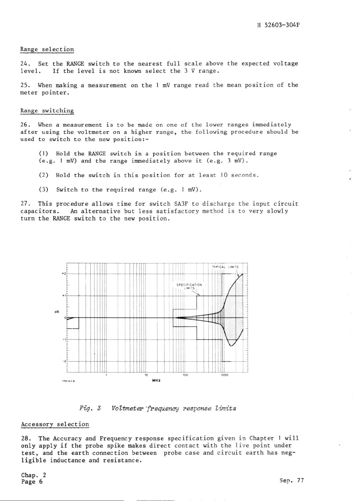
Fig.
Accessory selection
28. The Accuracy and Frequency
only apply
tes!,
and the earth connection between
if the
ligible inductance and resist,ance.
3
probe
Voltnetu'fneqteneA resporcse
response specification
spike makes dir.ect contact
||t i 1
SPECIFICATION
, LIMITS I
rl]jr-]ii
||it
probe
case
TYPICAL LIMITS
ti
Lünite
given
with the
and
circuit
in Chapter
live point
earth has neg-
I
will
under
Chap.
Page
2
6
Sep.77