

Marco T5, PB5, T10, PB10 User Manual
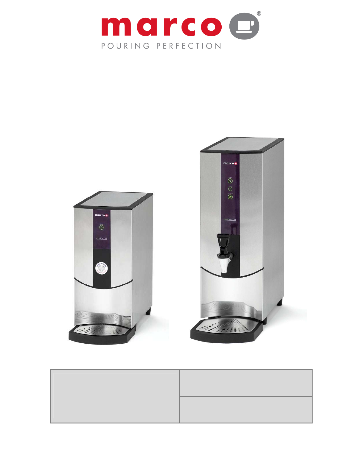
Ecoboiler
SERVICE MANUAL
Marco Beverage Systems Ltd.
63d Heather Road,
Ireland Tel: (01) 295 2674
Ireland Fax: (01) 295 3715
Sandyford Industrial Estate,
Dublin 18,
Republic of Ireland
UK Tel: (0207) 274 4577
UK Fax: (0207) 978 8141

CONTENTS:
1. INTRODUCTION 3
2. SAFETY INSTRUCTIONS 4
3. BASIC INSTRUCTIONS 5
3.1. Installation Details 5
3.2. Operation 5
3.3. Temperature Calibration 6
3.4. Time/Volume Dispense Calibration 7
3.5. Troubleshooting 7
3.6. Maintenance 8
3.7. Cleaning 8
3.8. Limescale 8
3.9. Cautions and Safety Tips 8
4. TECHNICAL DATA 9
4.1. General Description 9
4.2. External Arrangement 9
4.3. Access to internal components 10
4.4. Internal Arrangement 12
4.5. PCBs 12
4.5.1. PCB Layout 12
4.5.2. PCB Ecoboiler Control – 1600345 13
4.5.3. PCB Ecoboiler Display 5L – 1600348 14
4.5.4. PCB Ecoboiler Display 10L – 1600349 14
4.6. Troubleshooting – Diagnostic guide 15
4.7. Tank Components 16
4.8. Descaling procedure 17
4.9. Wiring Diagram 1000660 Ecoboiler T5 18
4.10. Wiring Diagram 1000661 Ecoboiler T10 19
4.11. Wiring Diagram 1000665 Ecoboiler PB5 20
4.12. Wiring Diagram 1000666 Ecoboiler PB10 21
4.13. Spare Parts List 22
PAGE
Service Manual 1000660 T5 1000661 T10 1000665 PB5 1000666 PB10 Ecoboiler 231109.doc Page 2 of 22

1. INTRODUCTION:
The information provided in this manual is intended to assist in the installation and maintenance of
the Marco Ecoboiler Water boiler. Please read the instructions carefully to prevent accidents and
ensure an efficient installation.
This manual is not a substitute for any safety instructions or technical data affixed to the machine or
its packaging. All information in this manual is current at the time of publication and is subject to
change without notice.
Only technicians or service providers authorised by Marco should carry out installation and
maintenance of these machines.
Marco accepts no responsibility for any damage or injury caused by incorrect or unreasonable
installation and operation.
Service Manual 1000660 T5 1000661 T10 1000665 PB5 1000666 PB10 Ecoboiler 231109.doc Page 3 of 22

2. SAFETY INSTRUCTIONS:
•
Read all instructions.
•
To protect against electric shock do not immerse mains cord in water or other liquid.
•
To prevent chafing of the cable, do not let the mains cord hang over the edge of a table or
counter ; or touch hot surfaces.
•
Do not operate any appliance with a damaged cord, plugs, or after the appliance malfunctions
or has been damaged in any manner.
•
Switch off at the mains (unplug or disconnect from outlet) and turn off the water supply when
not in use and before cleaning. Allow to cool before removing components.
•
The use of spares and accessories not recommended by Marco may cause damage and/or
injuries.
•
Do not use outdoors. Do not place on or near a hot gas or electric burner.
•
Do not use the appliance for anything other than its intended use.
•
Save these instructions.
Service Manual 1000660 T5 1000661 T10 1000665 PB5 1000666 PB10 Ecoboiler 231109.doc Page 4 of 22

3. BASIC INSTRUCTIONS:
3.1. INSTA L L ATION D E T AILS:
Elect rical ins t allation :
• ECO Boiler PB5, PB10, T5, T10 (2.8kW) - A moulded 13A plug is factory fitted. A suitable 13A
outlet is all that is required.
Plum b i ng inst a l l ation p r o cedure:
Note:
Marco recommend that this machine be positioned on a counter with a drainage facility.
Marco cannot be held responsible for any flood damages.
• Mains water pressure required (limits): 5-50psi (35-345kPa)
• Fit a stop Valve on a cold water line and attach a 3/4" BSP male fitting,
(e.g. 3/4" x 1/2" 311 or washing machine type stop valve).
• Connect straight tailpiece of the inlet hose to the stop valve fitting. Make sure that the preattached sealing washer is fitted.
• Turn on the water to flush any impurities, dust etc from the inlet hose and water pipe. Allow
several gallons through.
• Connect right-angled tailpiece of the hose to the inlet valve of the boiler (again 3/4" BSP).
Make sure the sealing washer is fitted here also.
• Turn on water and check for leaks.
3.2. OPERAT ION:
• Check that all installation procedures have been carried out.
• Ensure water valve is on.
• Plug boiler into 13A socket and press power button on the front of the machine marked
‘Power’. Refer to Figure 1.
NOTE: On a 5L machine the ‘Power’ button light also acts as the “Ready/Status” indicator.
• The “power on” light will glow green and the machine will fill to a safe level, above the
elements, before heating.
• The “Ready/Status” light will cycle two red flashes while the machine is filling to the safe level.
• After this amount of water has heated to about 96ºC the boiler will draw more water in until the
temperature drops by 1 or 2 degrees. The boiler will then heat again. This heat fill cycle
continues until the boiler is full.
• On a 5L machine, whilst the machine is above the safe level and filling, the “Ready/Status”
light will glow orange.
• On a 10L machine, whilst the machine is above the safe level and filling, the “Ready/Status”
light will remain blank.
• The “Ready/Status” light will glow green when the machine is both full and up to normal
operating temperature.
• The boiler is now ready for use.
Service Manual 1000660 T5 1000661 T10 1000665 PB5 1000666 PB10 Ecoboiler 231109.doc Page 5 of 22
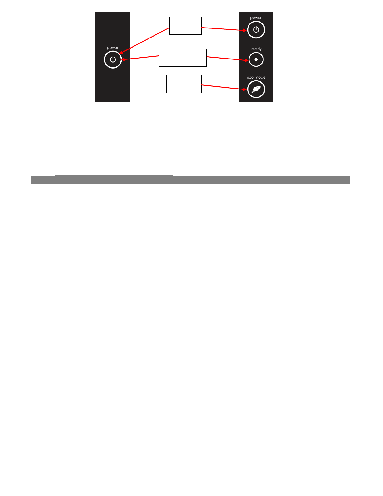
Power
Button
Indicator
Button
Ready/Status
Ecomode
5L Display
10L Display
Figure 1: Machine User Interface
NOTE:
Because the boiler is electronically controlled no priming is necessary.
The element cannot switch on until a safe level of water is reached.
3.3. TEMPE R ATURE CAL I BRATION
The Ecoboiler control PCB (1600345) has the ability to have the desired set-point temperature at
whatever setting is required. During manufacture of the PCB it is set to the default temperature of
around 80
o
C. During assembly the PCB is then calibrated to give a set point between 95oC-96.5oC.
If the temperature setting needs to be modified on-site please follow the steps below:
1. To Enter Calibration mode:
a. Turn the machine off at the mains power supply.
b. Then, whilst depressing the tactile switch on the PCB, turn the mains power back on.
c. All available LED’s on the front panel will now blink continuously.
d. The machine is now in Calibration mode.
2. In Calibration Mode the machine will heat continuously until the tactile switch on the PCB is
pressed for a second time (NB: The tactile switch should be pressed for at least 1 second)
3. Using a thermometer to measure the temperature at the thermistor pocket, the machine should
be allowed to reach the desired set-temperature. (NB: It may be necessary to let the unit cool
down if the desired set point is lower than the units current temperature)
4. At this point the tactile switch on the PCB should be pressed for at least 1 second.
5. Following a correct calibration procedure the tank temperature should be maintained within
o
C of the desired set-point temperature.
3
In the event of an incorrect calibration process the steps below should be followed:
6. If the tactile switch is pressed too early and the temperature is set lower than desired, the
tester should simply repeat steps 8-11.
7. If the tactile switch is pressed too late and the set temperature is too high, the tester will need
to wait for the temperature in the tank to cool, or add cool water, and then repeat steps 8-11.
Service Manual 1000660 T5 1000661 T10 1000665 PB5 1000666 PB10 Ecoboiler 231109.doc Page 6 of 22

switch machine off
3.4. TIME / V OLUME DI S P ENSE CAL I B R ATION
1. Open the front - bottom panel.
2. Make sure that the machine is powered, filled and heated (ready lamp green).
3. Press calibration tactile button on the PCB for a second until status lamp starts blinking red-green.
4. Set new dispense time by pressing dispense button to obtain the required output volume of water.
Button may be pressed several times – all times / volumes will be added together.
5. To confirm and save new value press calibration button on the PCB for a second until the status
lamp stops blinking.
6. Setting dispense time / volume to zero (omit step 4) will make the machine work as “push & hold”
(water dispensed as long as the button is pressed).
3.5. TROUB L ESHOOTING
The Ready/Status light signals various errors or problems.
A cycle of red flashes indicates an error. The number of flashes in a cycle corresponds to the
symptom in the table below:
Status/Diagnostic light guide:
No of
flashes
Symptom Action required
2
Water level below elements. Normal
when machine first fills.
Check water pressure , if this is OK then call
service agent.
3 Temperature sensor failure (o/c) Call service agent
4 Water not heating Call service agent
5 Temperature sensor failure (s/c) Call service agent
Check water pressure. If OK –
6 Machine not filling
and on again. If problem reoccurs - call service
agent.
Note: Some of the err o r sequen c e s will b e displ ayed i f there i s low w ater
press ur e. Plea s e check that ther e is wate r pressur e and tha t the wate r stopvalve is open b e fore ca lling you r service agent.
For a more det a iled des cription o f error indicato r s and co r r ective a c tions s e e
secti o n 4.7 o f this man u al.
Service Manual 1000660 T5 1000661 T10 1000665 PB5 1000666 PB10 Ecoboiler 231109.doc Page 7 of 22
 Loading...