

Marchand Electronics XM9L-KK, XM9L-3KK, XM16L-3KK, XM16L-KK, XM9L-3WAY Assembly Manual
Marchand Electronics Inc.
XM9L-KK, XM9L-3KK, XM16L-KK, XM16L-3KK, XM9L-3WAY
High Performance Electronic Crossover.
Assembly of DeLuxe Cabinet
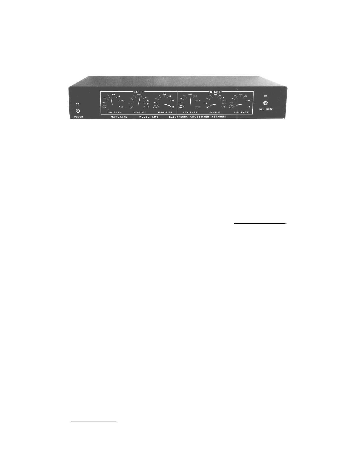
The high performance crossover kits have a cabinet, front
panel controls, rear panel connectors and power cord.
The kits also include a PS10-K power supply. The 2 way
units also have two crossover boards. The 3 way units
have 4 crossover boards.
The assembly of the four different models is very similar.
The differences between the four models will be
indicated in the text where appropriate.
Install the fuse holder in the panel. The white washer is
installed on the outward side. Gently tighten the nut. Too
much force will crack the housing.
Install the line cord using the strain relief. Place the strain
relief 9" from the end of the line cord and squeeze tightly
with pliers. Insert the cord and strain relief into the hole in
the rear panel until it snaps in.
The assembly of the rear panel is now complete. Put it
aside until later.
Assembly of Rear Panel
The rear panel holds the RCA connectors and the power
cord and the fuse holder.
Install the 6 ( 8 for 3-way) RCA connectors in the holes
input, high pass, low pass. The 3-way unit also has two
connectors in the holes marked mid. The left channel has
the connectors with the BLACK insulators. The right
channel gets the RED insulators. Each connector has two
insulators, one with a shoulder and the other is flat. Make
sure the shoulder is inserted in the hole of the panel.
Install the flat insulator on the other side of the panel.
Install the solder lug and the nut. Tighten the nut well.
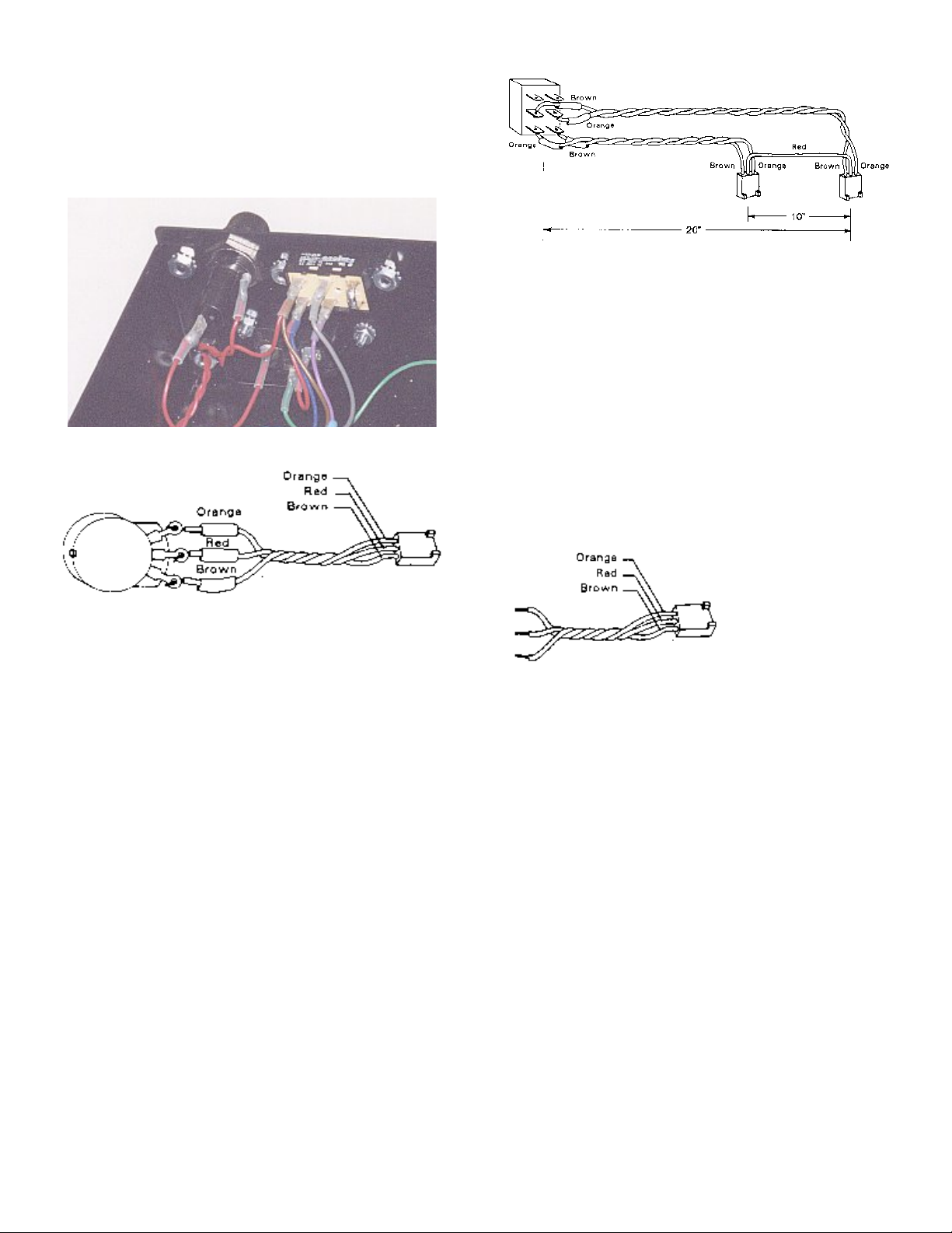
Attach wires to the RCA connectors. Prepare 4 (6 for 3way) pairs of wire by taking a 10" length of red and brown
wire and twisting together. Slip a 3/4" length of heat shrink
tubing over the end of each wire at one side of the pair.
Strip 1/4" of insulation off each wire. Solder the brown wire
onto the solder lug of the connector. Solder the red wire
into the center pin of the connector. Slip the heat shrink
tubing over the solder joints. Shrink the tubing with a heat
gun. If no heat gun is available use the heat of a soldering
iron.
Repeat this for all RCA connectors.
The two way units come with detachable line cord and a
power voltage selector switch. The 3-way units have an
attached line cord.
Please use the appropriate instructions below.
Attached line cord
Removable line cord
Install the voltage selector switch using the 6/32 hardware.
Install the power entry module using the 6/32 hardware.
Install the fuse holder. The assembly of the rear panel is
now complete. Put it aside until later.
Assembly of Shell
First assemble the PS10-K power supply and the XM9 or
XM16 crossover boards according to the instructions
provided. Note: (1) Do NOT install the board mounted
RCA connectors that are normally provided with the
crossover kits. They are not used in the high performance
crossover. (2) Replace the LF353 op amps with the better
op amps. On the XM9 boards the OPA2134 is inserted in
positions IC1, IC2, IC3 and IC4. On the XM16 the
OPA2134 is inserted in positions IC1, IC2, IC3, IC4, IC5
and IC6. Please make sure that the IC's are installed
correctly.
Place the shell on a flat surface with the bottom down.
Notice the pattern of four holes near one side of the
bottom of the shell. Place the shell so that this pattern is
on the left hand side. The front of the cabinet is now
towards you.
Install the PS10 power supply with 4 standoffs in the 4
holes on the left of the cabinet, as described above. The
two position terminal block of the PS10 faces towards the
rear of the cabinet.
The crossover boards will now be installed temporarily.
Notice the 4 rectangular patterns of 10 holes in bottom of
the shell Each pattern hold a crossover board. The
© 2000 Marchand Electronics Inc. PO Box 473, Webster, NY, 14580 www.marchandelec.com (716) 872 0980 FAX: (716) 872 1960
1
crossover boards are placed with P6 and P7 facing the
rear of the cabinet. Use 4 standoffs to install each board.
Use the second hole from the rear of the shell for the
standoffs. The XM9 then also uses the fourth hole and the
XM16 uses the fifth hole from the rear. For the 2-way units
mount the two crossovers in the two center positions in
the shell.
Figure 1 Power entry with voltage selector switch.
5 black buttonhead screws or flathead screws.
Figure 3: Sum-mode switch cable
Putting it all together
Prepare 2 (4 for 3-way unit) cables as shown in Figure 4.
The two way unit uses one cable 8" long and another 11"
long. The 3-way unit has two additional cables 6" long and
15" long.
Insert all the orange wires from each of the power cables
into the terminal block on the PS10 marked +.
Cut a piece of red wire 3" long and strip 1/4" of insulation
from each end.
Gather the red wires from the power cables and one end
of the 3" red wire and insert them into the terminal block
on the PS10 marked GND.
Figure 2: Potentiometer Cable
Assembly of Front Panel
Install the 6 (4) 10K potentiometers in the positions
labeled level and damping. Tighten the nuts well. One
DPDT switch mounts in the position marked power and
the other DPDT switch mounts in the position marked
sum. There is a hole left for the indicator LED. Do not
install this LED yet at this time.
Install wires to potentiometers. Prepare 3 8" lengths of
red, orange and brown wire. Strip 1/4" of insulation from
each end. Solder one end of each wire to a potentiometer,
as shown in Figure 2. Note the color orientation. Use 3/4"
of heat shrink tubing over each potentiometer terminal.
Shrink with heat gun. Solder a metal terminal to the free
end of each wire. Insert the terminals into the 3 -pin
female Molex connector. Be sure to insert the proper
colors into the proper connector positions.(Note: all of the
3-pin female connectors in this kit use the same color
orientation).
Twist the wires to form a 3-wire cable.
Repeat above step for all potentiometers.
Install wires to the sum mode switch as shown in . Be
careful to use the right color wires as shown. Use heat
shrink tubing as indicated. Some kits come with a DPST
rocker switch instead of the toggle switch. The rocker
switch does not have the two unused terminals that are
shown in .
The front panel will be attached to the main chassis using
Figure 4: Power cable
Cut a piece of brown wire 3" long and strip 1/4" of
insulation from each end.
Gather the brown wires from the power cables and one
end of the 3" brown wire and insert them into the terminal
block on the PS10 marked --.
Double check: RED is GND, ORANGE is + and BROWN
is -.
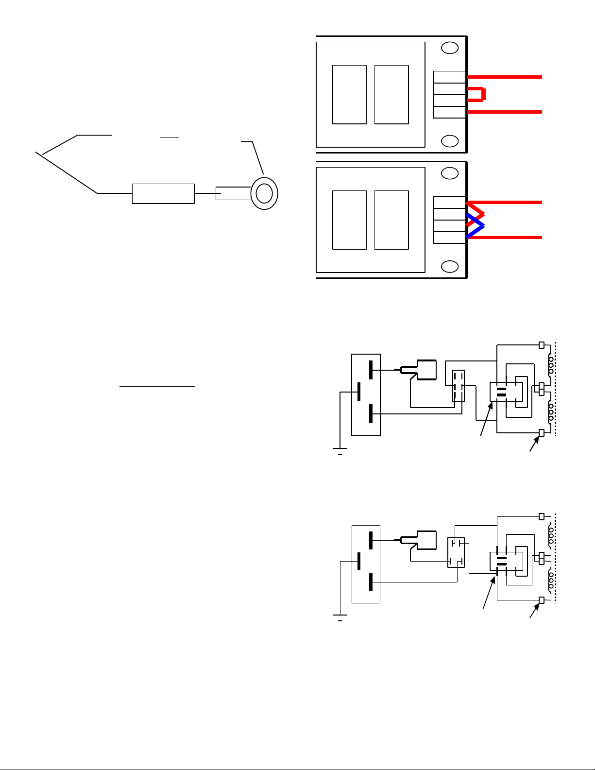
Identify which end of the LED is the cathode (negative)
lead. The LED has a flat on its side next to this lead. Trim
both leads to about 1/4".
Cut both leads of the 10K resistor to 1/4" long.
Solder one of leads of the resistor to the cathode of the
LED.
Using 1" of heat shrink tubing, connect the free end of the
3" brown wire (from the negative terminal of the power
supply) to the free lead of the resistor. slide the tubing
over the resistor, against the LED, to cover the
connections on both ends of the resistor.
Using 1/2" of heat shrink tubing, solder the red wire from
the ground terminal of the power supply to the remaining
lead of the LED (anode).
The PS10 power supply of the crossover should be
grounded to the cabinet through a power resistor.
Solder one lead of the power resistor to the solder lug.
Solder a 3” length of wire to the other end of the 2.4K
© 2000 Marchand Electronics Inc. PO Box 473, Webster, NY, 14580 www.marchandelec.com (716) 872 0980 FAX: (716) 872 1960
2
power resistor.
Solder lug
Resistor
Wire to PS10 output
ground
220VAC
110VAC
PS10
PS10
Front Panel
DPDT switch
Rear Panel
Fuse Holder
Rear Panel
Power entry
Rear Panel
Voltage selector
GREEN/
YELLOW
N
L
PS10 transformer
terminal block
WHITE
BLACK
WHITE
BLACK
BLACK
BLACK
BROWN
RED
RED
Wire to
case
Front Panel
DPST rocker switch
Rear Panel
Fuse Holder
Rear Panel
Power entry
Rear Panel
Voltage selector
GREEN/
YELLOW
N
L
PS10 transformer
terminal block
WHITE
BLACK
WHITE
BLACK
BLACK
BLACK
BROW N
RED
RED
Wire to
case
WHITE
Install the shrink tubing over the resistor and part of the
solder lug.
Attach the solder lug to the cabinet using a 6-32 screw
and nut. Use one of the available holes near the PS10.
Insert the free end of the wire in the center terminal of
the three position terminal block of the PS10 output. This
is the neutral DC output.
Figure 5
Install the LED into the front panel. First insert the black
grommet through the hole in the front panel from the
outside. Then insert the LED into the grommet from the
inside. The grommet snaps around the base of the LED
and holds it in place.
Check that all the pieces of heat shrink tubing are properly
positioned over the connections they are supposed to
protect and shrink with a heat gun.
Now the AC power wiring will be hooked up to the power
supply.
Figure 6
Attached line cord
Separate the power cord wires back to about 1/4" from
the strain relief and cut one of the wires about 2" from the
strain relief. Slip 1/2" of heat shrink tubing over the short
wire and solder it to the center connector of the fuse
holder. Cut 1/2" of heat shrink tubing and slip it over the
remaining power cord wire. Solder the wire to the center
connector of the power switch.
Cut an 8" piece of red high voltage (thick insulation)
hookup wire, strip 1/4" at each end and solder to the
bottom terminal of the power switch. Use 1/2" of heat
shrink tubing over this connection as well.
Secure the free end of the wire in the leftmost terminal of
the 4-position terminal block (AC input) on the PS10
power supply board.
Cut a 2" piece of brown high voltage hookup wire and
secure the free end of the wire in the rightmost terminal of
the 4-position terminal block (AC input) on the PS10
power supply board.
Use jumpers on the 4-position terminal block of the PS10
power supply to select line voltage, as shown in Figure 6.
Figure 7. Power entry with voltage selector switch on rear
panel and toggle switch on front panel.
Figure 8. Power entry with voltage selector switch on rear
panel and rocker switch on front panel.
© 2000 Marchand Electronics Inc. PO Box 473, Webster, NY, 14580 www.marchandelec.com (716) 872 0980 FAX: (716) 872 1960
3

Connect the 2 (4) power cables from the power supply to
Removable line cord
Refer to Figure 1 and Figure 7 or Figure 8 when
installing the power supply wiring for the removable line
cord. If your kit has a DPDT toggle switch then use
Figure 7. If your kit has a DPST rocker switch the use
Figure 8.
Two rocker switches are included in the kit that has
rocker switches. The illuminated switch with the colored
lens is used for the power and the one without the lens is
used for the sum switch. Note that the rocker switch has
two pairs of contacts; one pair is closer together than the
other. Use the pair that is cose together for the wires that
go to the transformer.
Use high voltage (thick insulation) #22 hookup wire to
make the connections between the power entry
connector, the power switch on the front panel and the
power selector switch on the rear panel and the fuse
holder. Install heat shrink tubing over all junctions. Use
wire colors as shown in .
Make sure to securely install the grounding wire between
the ground terminal on the power entry connector and
the chassis. Solder a 3” piece of green/yellow hookup
wire to one of the solder lugs provided. Solder the free
end of the wire to the ground terminal and secure the
solder lug to the chassis with one of the 6/32 screws
holding the rear panel.
Set the voltage selector switch to the proper voltage
before proceeding.
Attached AND Removable line cord
Install a 1A fuse in the fuse holder.
We will now test the power supply. Plug the cord in and
turn on the power switch. The two LED indicators on the
power supply and the front panel LED indicator should all
light.
UNPLUG the power cord before proceeding.
Now the RCA connectors are to be connected to the
circuit boards. Note that the circuit boards have groups of
3 holes marked P6,P7,P8 on the XM9 and P5,P6,P7 on
the XM16. The twisted pairs from the RCA connectors
connect to these locations according to the tables below.
There are four tables (1..4), one for each configuration of
the crossover network. Be sure to solder the red wire to
the small hole in the center of the group, and the brown
ground wire to one of the 3 larger holes in the group. The
boards will have to be removed in order to do the
soldering. On the 3-way units there also is a set of two
jumper wires between the boards. Make the jumper
connection by running a red wire between the center holes
of the locations indicated and a brown wire between the
grounds at the locations indicated. For example, for the
XM16L-3KK there is a jumper wire between P5 of the left
board and P7 of the left center board, etc.
There are several trimmer potentiometers on the
crossover boards. They should all be set to the center
position.
© 2000 Marchand Electronics Inc. PO Box 473, Webster, NY, 14580 www.marchandelec.com (716) 872 0980 FAX: (716) 872 1960
the crossover boards. On the XM9 the cables are plugged
into connectors marked P2. On the XM16 the power
cables are plugged into the connectors marked P1.
The sum-mode cable is hooked to two 3-pin molex
connectors according to the table 5.
The level and damping controls are hooked up
according to table 6.
There are several jumpers on each board. These
jumpers serve to enable the off board level and damping
controls. Near each connector that was used in table 6
there is a 3 position male connector, labeled 1J2 or 3J4 or
5J6. A jumper block should be placed on each of these
connectors. If a cable was connected to the P connector,
then the jumper should be placed over the RIGHT two
pins. If no cable was connected the jumper should be
placed over the LEFT two pins.
Make sure all the jumpers have been installed.
Install the control knobs onto the level and damping
controls. The knobs should be installed so that the arrow
indicator on the knob is at the 12 o'clock position when the
control is centered. The position of the knob when it is
turned fully clockwise is thus left-right mirrored from when
it is turned fully counterclockwise. When installed in this
symmetric fashion, the calibration on the front panel will be
correct.
3-Channel Unit
The 3-channel unit use 3 crossover boards and one LD28
summer board. There is no sum switch. The LD28 board
is installed to the left of the 3 crossover boards, as seen
from the front of the unit. The power supply cable to the
LD28 is the same as for a crossover board. The output
marked OUT4+ of the LD28 Should be connected to the
connector marked “sum” on the rear panel. The 3 inputs
marked IN1, IN2 and IN3 should be connected to the low
pass outputs of the crossover boards. Use black/red
twisted wire pairs for these connections; the red wire being
the signal and the black wire the ground. Note that the
low-pass outputs of the crossover boards now have two
connections each: to the output connectors and to the
summer board.
Frequency Modules
Install the frequency modules for the proper frequencies.
For the two way units all frequency modules have the
same value. On the 3 way units, install the frequency
modules with the LOWER frequency into the Left and
Right-center boards, and the frequency modules with the
HIGHER frequency into the Left-Center and Right boards.
The Top Cover of the unit can be installed now or at a
later time. Fasten the top with 4 6/32 x 1/4" screws. In
case it is difficult to insert the screws, loosen the screws
that hold on the front and rear panels and try again. Now
fasten all screws well.
The assembly is now completed.
4
 Loading...