

Marchand Electronics XM9 User And Assembly Manual

Marchand Electronics Inc.
Electronic Crossover Circuit Board
Model XM9
(c) 1990....2015 Marchand Electronics Incorporated
Users Manual
Assembly Manual
Marchand Electronics Inc. Rochester NY
Last updated 5 March 2015
www.marchandelec.com

XM9 ELECTRONIC CROSSOVER NETWORK
Steep 24 dB/octave slope Crossover frequency 20 - 5000 Hz.
Outputs are always in phase Small 3.2" x 4.2" circuit board
Level controls on board Optional off board level controls
Subwoofer summing option On board RCA in/out connectors
No turn on/off transients Fourth order constant voltage design
Low noise circuit design Double sided cicuit board
The XM9 electronic crossover network module is a fourth order
constant voltage crossover design. The module provides both lowpass and high-pass outputs. The slope of both outputs is 24
dB/octave. Because of the fourth order design the high-pass and
low-pass outputs of the crossover are always in phase with each
other. The crossover network is implemented as a fourth order
state variable filter. This filter provides both the high-pass and lowpass function simultaneously, guaranteeing a near perfect match
of the high pass and low-pass responses.
One crossover network is needed for each channel of a biamplified system. A tri-amplified system needs two networks per
channel, one to separate the high frequencies from the mid-low
frequencies and another one to separate the low and mid
frequencies. A quad system needs 3, and so on. The filter can also
be used to drive a subwoofer, where the subwoofer is shared by
the two channels of the stereo system.
The crossover frequency of the XM9 electronic crossover can
easily be changed by changing the value of four resistors. These
four resistors are mounted on an 8 pin DIP header plug for ease of
change.
Individual level controls for the high and low pass outputs are
provided with on board potentiometers. A damping control
potentiometer on the circuit board allows for adjustment of the
frequency response at the crossover frequency. A boost or cut of
INSTALLATION AND USE.
up to 6 dB at the crossover frequency compensates for a dip or
bump in the response at the crossover frequency found in some
systems.
A time delay relay at the outputs of the XM9 eliminates the
transients that can happen when the unit is turned on or off. Off
board controls for the damping and the levels can also be used
with the XM9.
The XM9 electronic crossover is built on a 3.2" X 4.2" printed
circuit board of high quality glass-epoxy material. One side of the
double sided circuit board acts as a ground plane for the circuit.
This contibutes to the very high signal quality of the XM9. A silk
screen on the component side makes assembly very easy. The kit
uses only high grade components: 1% metal film resistors, 1%
matched polypropylene film capacitors for the filter capacitors,
three dual FET input and one bipolar operational amplifier.
Connectors for input, output and power make for easy assembly.
The XM9 is available as a bare board, with only the PC board and
the assembly manual; as a kit, with all needed components,
including a set of cable connectors; or completely assembled. The
frequency module consists of an 8 pin DIP header and 4 1% Metal
film resistors. The optional level/damping control potentiometer
and cable assembly can be used for mounting the level control on
a cabinet front panel. One of these XM9-PT is required for each
low-pass, high-pass and damping control.
The typical application for the XM9 electronic cross-over filter is to
separate the high and low frequency bands in a multy-way audio
system. Figure 1 shows the application in a two-way amplifier
setup. The signal from the pre-amp is connected to the input of
the crossover. The high pass output from the cross-over is
connected to the input of the power amplfier driving the high
frequency loudspeaker (tweeter), while the low pass output is
connected to the amplifier driving the low frequency speaker
(woofer).
SPECIFICATIONS:
Frequency response: DC to 100 KHz, +/- 0.2 dB
Crossover frequency: 20 Hz - 5 KHz
Insertion gain: 6dB with level controls at maximum.
Filterslope: 24 dB/Octave
Harmonic distortion at 1KHz: less than 0.001%
Signal to Noise ratio: better than 110dB
Input impedance: 25 KOhm
Output load capability: 2 KOhm min.
Output impedance: 50 Ohm typ
Maximum input voltage 10 V peak-peak (4 V RMS)
Power supply requirement: dual regulated +15V and -15V @50 mA, typ
2

The controls and jumpers on the circuit board have the following function:
LEVEL CONTROLS:
There are two level control potentiometers on the circuit board,
one for the low pass output and one for the high pass output. They
DAMPING CONTROL:
The damping control sets the frequency respose of the unit at the
crossover point. The range of the damping control is from -8 dB to
+6 dB, at the crossover point. This adjustment is usefull for
matching the frequency response of the high and low
loudspeakers at the crossover point. In the center position the
frequency response is totally flat, meaning that the sum of the
-------------------------------------------------| Table 1. |
| Connector pin assignments. |
| Connector Pin # Signal description |
|==================================================|
| - P1 | 1 | Low pass level control, signel |
| P1 | 2 | Low pass level control, wiper |
| P1 | 3 | Low pass level control, ground |
| - P2 | 1 | -15 Volt power, 15 mA, typ. |
| P2 | 2 | Power ground |
| P2 | 3 | +15 Volt power, 15 mA, typ. |
| - P3 | 1 | Damping control, ground |
| P3 | 2 | Damping control, wiper |
| P3 | 3 | Damping control, signal |
| - P4 | 1 | High pass level control, signel |
| P4 | 2 | High pass level control, wiper |
| P4 | 3 | High pass level control, ground |
| - P5 | 1 | Subwoofer output |
| P5 | 2 | Ground |
| P5 | 3 | Subwoofer input |
| - P6 | | Signal input, RCA jack |
| - P7 | | High pass output, RCA jack |
| - P8 | | Low pass output, RCA jack |
--------------------------------------------------
each have a range of off to +6dB. At the center position the
crossover network has unity gain (0 dB).
output voltage of the high pass and low pass channel is constant
for all audio frequencies.
FREQUENCY CONTROL AND FREQUENCY MODULE:
The crossover fequency of the XM9 can be set by installing the
apropriate frequency module. When using a subwoofer, with
standard full range loudspeakers, the crossover frequency will
normally be set at about 70-150 Hz. When using the crossover
network in a typical biamping setup the crossover frequency is
often set at 500-2000 Hz. These frequencies depend on the
loudpeakers used.
3
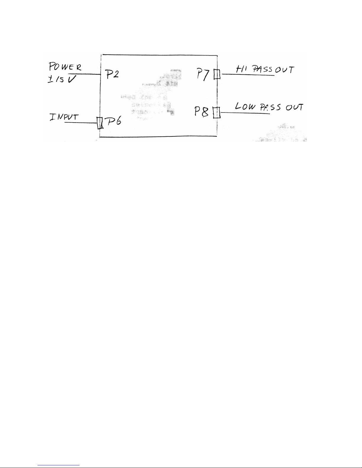
Fig 1. XM9 hookup.
Off board volume controls can be used to the high anw low pass
outputs and damping control of the XM9. Best results are
achieved when using 10 K potentiometers with linear taper. The
potentiometers should be connected with the wiper at pin 2 (center
pin) and the outside leads to pins 1 and 3 of the connector. See
table 1. The jumpers should be moved according to table 2. The
low pass control is connected to P1, the high pass control to P4
and the damping control to P3.
4
-------------------------------------------------| Table 2. |
| Jumpers for external controls |
| On Off Selected control |
|==================================================|
| J1 | J2 | Low pass level control, External |
| J2 | J1 | Low pass level control, On board |
| J3 | J4 | Damping control, External |
| J4 | J3 | Damping control, On board |
| J5 | J6 | High pass level control, External |
| J6 | J5 | High pass level control, On board |
--------------------------------------------------
Fig 10 shows some typical arrangements for 2-way, 3-way and 4way installations. For driving long lines a line driver buffer amplifier
may be needed. The XM9 outputs can drive shielded cable lines
of up to about fifty feet. The XM9 is implemented with a fourth
order state variable filter,(see schematic diagram). The filter is
implemented with the Bi-Fet op-amp's IC1 and IC2. The virtue of
Fig 3. Example of subwoofer application.
this type of filter is that it provides simultaneous high-pass and
low-pass functions at the two ends of the chain of four integrators.
This means that only 4 precision capacitors are needed in order to
implement both fourth order functions. Both high-pass and lowpass functions will be perfectly matched, because they are derived
from the same network.
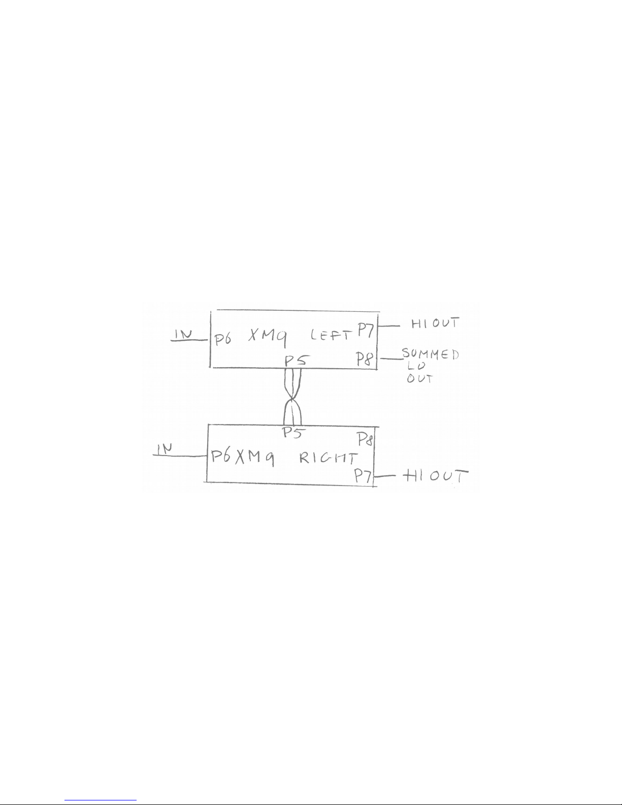
Two XM9 crossovers can be hooked up for driving a common
subwoofer. In this case the low pass outputs of the two
crossovers are summed together. Connector P5 is used for this
purpose. The two crossovers are connected together with a cable
-------------------------------------------------| Table 3. |
| Cable for common subwoofer |
| P5 board A P5 board B |
|==================================================|
| pin 1 connected to pin 3 |
| pin 2 connected to pin 2 |
| pin 3 connected to pin 1 |
--------------------------------------------------
COMMON SUBWOOFER
from P5 on one crossover to P5 on the other. Table 3 showd the
wiring of the cable. Use a cable of not more than 30". Unshielded
wire can be used. The summed output can be taken from the low
pass output of either crossover board.
POWER SUPPLY
5
 Loading...