

Page 1

User’s Guide
Electronic Crossover Network
XM66 Variable Frequency
XM9 24 dB/octave
XM16 48 dB/octave
XM44 24/48 dB/octave
XM26 24 dB/octave Tube
XM46 24 dB/octave Passive Line Level
XM126 24 dB/octave Tube
Marchand Electronics Inc.
Rochester, NY
(585) 423 0462
www.marchandelec.com
Page 2
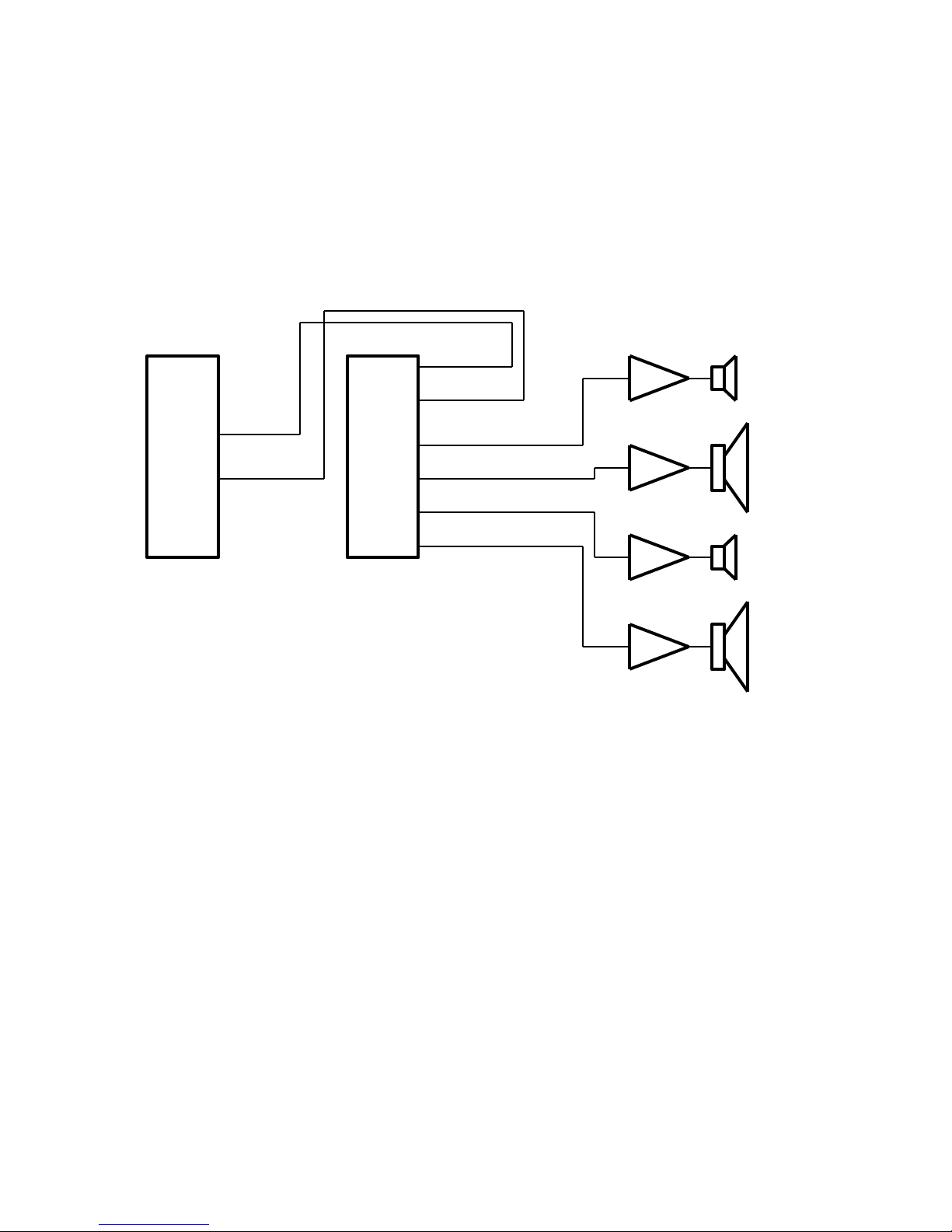
The electronic crossover is used to drive individual loudspeakers for separate portions of the
audio frequency spectrum. A two way crossover is used for bass and high frequency speakers. A
three way crossover is used when driving bass, midrange and high frequency speaker. The signal
from the preamp is passed to the electronic crossover network. The outputs of the crossover
network are then connected to the power amplifiers for the individual loudspeakers as in Figure 1 .
A typical configuration like this might have the crossover frequency set at 300 to 1000 Hz,
depending on the type of loudspeakers used. When used with subwoofers as low frequency
speakers, the typical crossover frequency is around 100 Hz. The range is 50 to 150 Hz for most
subwoofers. When the crossover frequency is below 100 Hz there usually is no stereo information
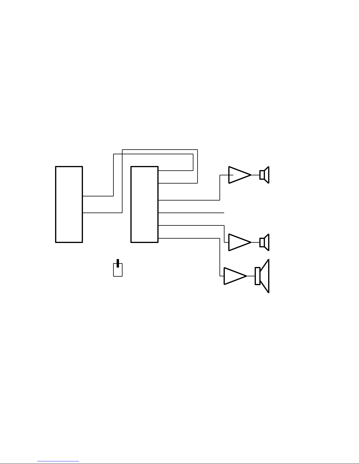
present from the sound of the subwoofer, and a common subwoofer can be used. Figure 3 shows
how to use the crossovers with a common subwoofer. The sum switch on the crossover front
panel causes the outputs of both low pass channel to be summed together. Both outputs will have
the same summed signal on them, and either one can thus be used to drive he common
subwoofer. The advantage of a common subwoofer is more than just cost. Because there is only
one subwoofer present, often a larger unit can be chosen, with an extended bass range.
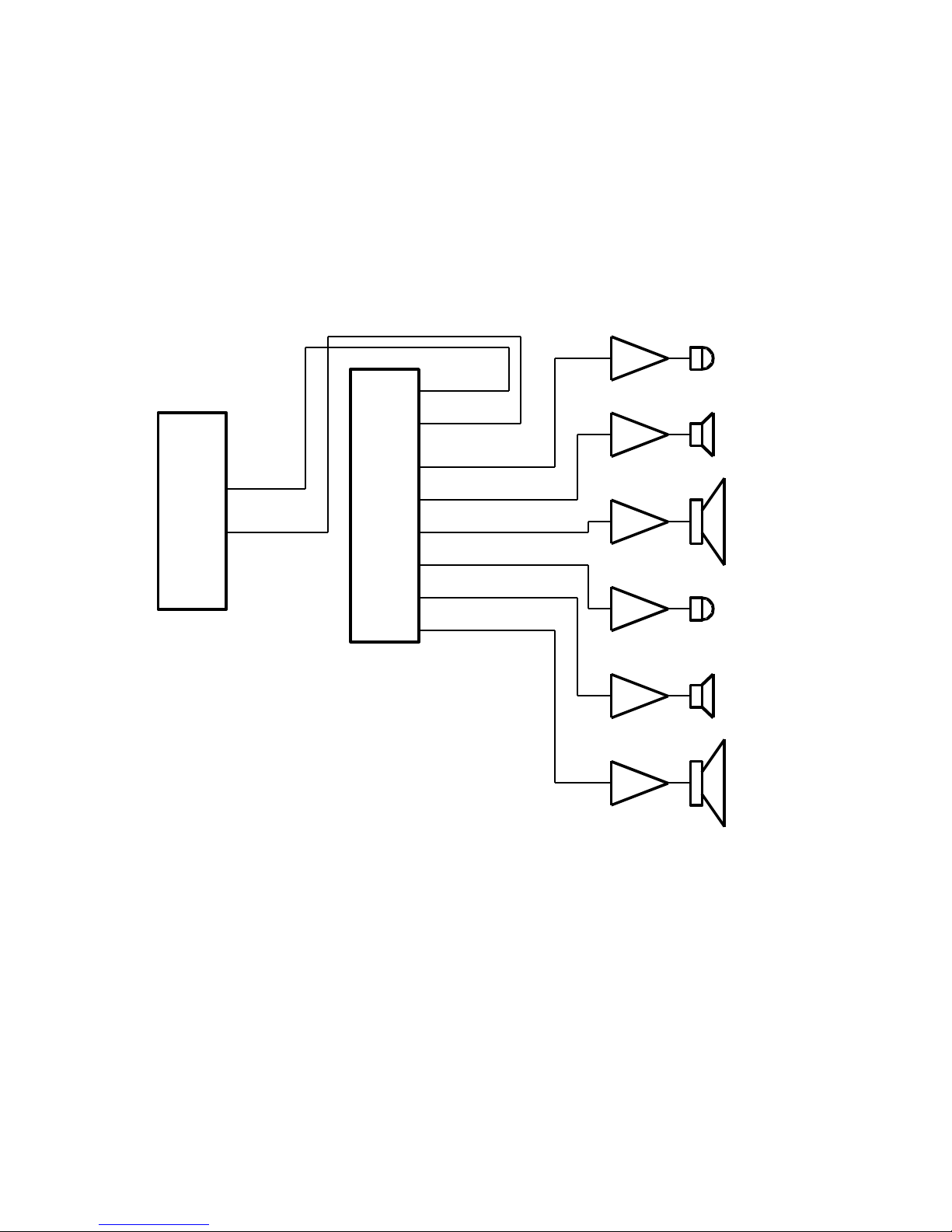
It is also possible to drive more than two speakers per channel. Figure 2 shows a three way
system with woofers, midranges and tweeters.
Choosing the crossover frequency and slope
At frequencies below the crossover frequency the signal will go to the low pass outputs. At
frequencies above the crossover frequency the signal will go to the high pass outputs. There is a
region around the crossover point where the signal will come out of both the high pass output and
the low pass output. For he crossover networks with a slope of 24 dB/octave (XM6, XM9 and
XM26) the width of this region is about 1/2 octave. For the XM16, with a slope of 48 dB/octave,
the width of this region is halved to 1/4 octave.
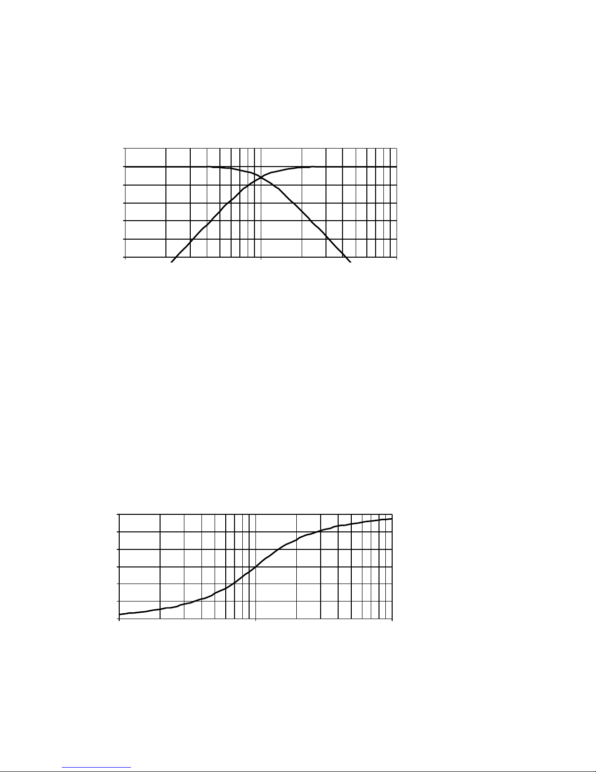
Figure 4 shows the frequency response of the 24 dB/octave crossover networks (XM6, XM9 and
XM26). The figure is drawn for a crossover frequency of 100 Hz. For other crossover frequencies
© 2017 Marchand Electronics Inc. www.marchandelec.com.
2
Amp
Amp
Left
High
Left
Low
C
r
o
s
s
o
v
e
r
Left High Out
Right Low Out
Right High Out
Right
High
Right
Low
Left Low Out
P
r
e
a
m
p
Right In
Left In
Left Out
Right Out
Amp
Amp
Figure 1
Two-way system has separate amplifiers for high and low range speakers
Page 3
the same figure applies, with the frequency scale scaled. Note that both the high pass response
and the low pass response are down exactly 6 dB at the crossover point of 100 Hz. This means
that at this frequency the amplitude is exactly half. Adding the high pass and low pass together
sum to unity. As a matter of fact the sum of the high pass and the low pass response is unity for
all frequencies. This is why the filter is called a “constant voltage network. It is also called a
Linkwitz-Riley network, after the two writers who first introduced this concept in the audio world.
The frequency response of the phase of the 24 dB/octave network is shown in Figure 5. The
frequency response of the phase is the same for the high pass and the low pass outputs. Note
that at the crossover point the phase shift is exactly 180 degrees.
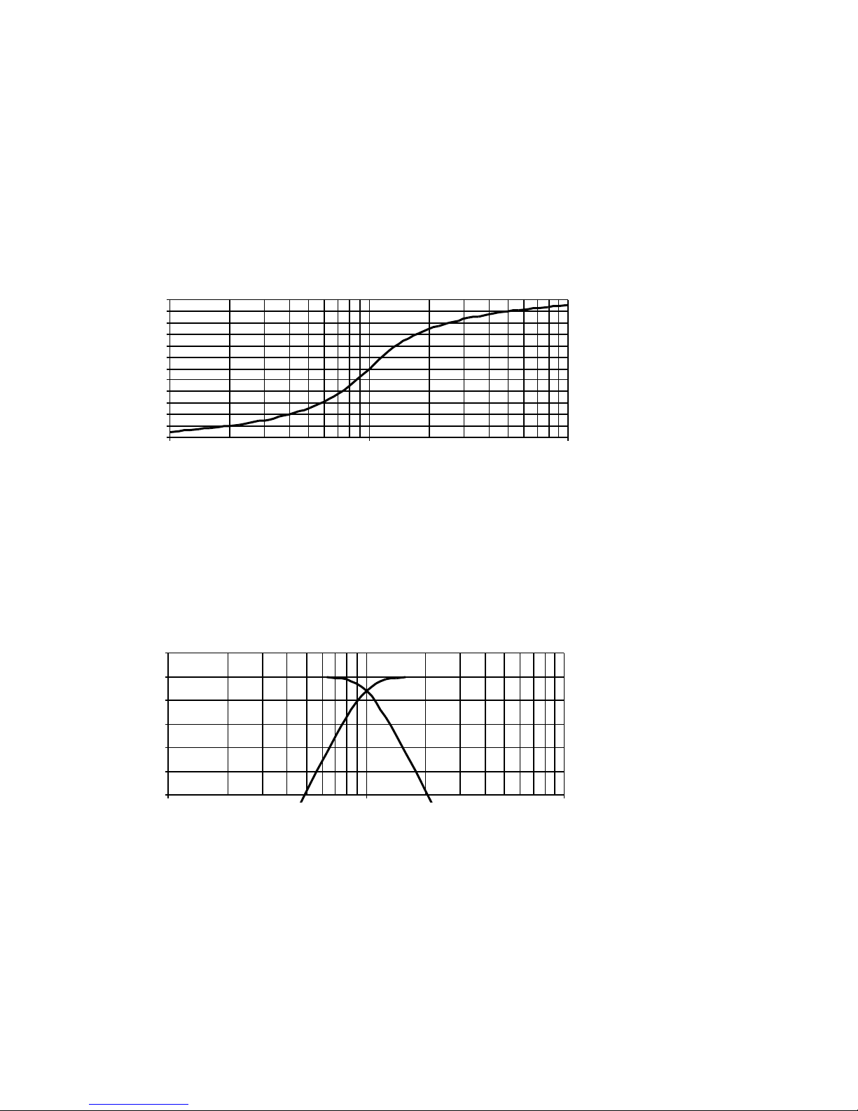
Figure 9 shows the frequency response of the XM16 crossover network. This network has a slope
of 48 dB/octave. Figure 8 shows the phase response of the XM16 crossover network. Note that
the phase shift of the XM16 is twice that of the other networks. The XM16 does not have a
damping control.
The choice of the crossover point is a difficult one, and often some trial and error is needed for
achieving best results. With the 24 dB/octave crossover networks a good rule of thumb is to set
the crossover point at least one half to one octave away from the cutoff frequency of the speaker.
Thus a satellite with a cutoff frequency of 50 Hz at the low and that is used with a subwoofer
requires a crossover frequency of 75 to 100 Hz. The subwoofer should then also have a range
extending half to one octave above the crossover frequency. In this case, if 100 Hz was chosen,
the subwoofer should have a range of at least 200 Hz.
© 2017 Marchand Electronics Inc. www.marchandelec.com.
3
Amp
Amp
Left
Mid
Left
Woofer
C
r
o
s
s
o
v
e
r
Left Mid Out
Right Mid Out
Right High Out
Right
Tweeter
Right
Woofer
Left Low Out
P
r
e
a
m
p
Right In
Left In
Left Out
Right Out
Amp
Amp
Amp
Right
Mid
Left
Tweeter
Right Low Out
Left High Out
Amp
Figure 2
Three-way system has separate amplifiers for tweeters, midrange and woofers
Page 4
A 48 dB/octave crossover should be chosen if this choice is not practical. This crossover with the
steep slopes can be used with a crossover frequency 1/4 octave away from the loudspeaker
cutoff point.
Changing the crossover frequency
Frequency modules
The XM6 crossover network has a control on the front panel to change the crossover frequency.
The frequency is shown on a four digit LED numeric display on the front panel of the unit. The
range is 20 Hz to 4500 Hz, and the frequency can be changed in steps of about 5%. A total of
160 frequencies are thus available. This nice feature comes with a cost. The XM9, XM16 and
XM26 use frequency modules to change the crossover frequency. These low cost modules are
plugged into a connector in the unit. The power has to be shut off and the top cover of the unit
removed. The module for the XM9 has 4 resistors on it. The module for the XM16 has 8 resistors
and the module for the XM26 has 4 resistors and four capacitors. The XM9 requires two modules
and the XM16 and XM16 require four modules for each crossover frequency chosen. These
modules are available for most frequencies. The manuals for the individual units have formulas in
them to compute the value of the resistors and capacitors. When ordering replacement modules
only the desired frequencies need be specified.
In order to replace the frequency modules the top cover of the unit needs to be removed. Undo
the two screws on each side of the unit and lift the cover. Make sure the power to the unit is
turned off. Proceed as follows:
XM9 Each circuit board has one frequency module. The same module sets both the high pass
and the low pass crossover point. It is inserted in a socket. The frequency module has four
resistors on it. Replace each module with the new module.
© 2017 Marchand Electronics Inc. www.marchandelec.com.
4
Amp
Left
Satellite
C
r
o
s
s
o
v
e
r
Left High Out
Right Low Out
Right High Out
Right
Satellite
Common
Subwoofer
Left Low Out
P
r
e
a
m
p
Right In
Left In
Left Out
Right Out
Amp
Amp
Sum Switch up
Figure 3
Two-way system with common subwoofer. The two low pass channels are summed when the
sum mode is selected.
Page 5
XM16 Each circuit board has two frequency modules on it, one for the low pass and one for the
high pass crossover point. The two points are usually set at the same frequency. Each module
has eight resistors on it. Replace each module with the new module.
XM26 Each circuit board has two frequency modules on it, one for the low pass and one for the
high pass crossover point. The two points are usually set at the same frequency. Each module is
a small circuit board with 10 gold plated contact fingers. Modules have precision capacitors and
resistors on them. The module on the left of each circuit board is the low-pass module; the other
one is the high pass module. Make sure to insert the modules so that the components on it face
away from the tubes. The tubes get hot and might melt the capacitors.
After replacing the module put the cover back on and install the four screws.
Level controls
The level controls on the front of the cabinet are used to set the volume of each loudspeaker.
There are several ways to adjust these controls. A good way to do this is to start out by setting all
controls in the center (12 o’clock) position. Listen to some music and adjust the controls for proper
volume from each speaker.
If a frequency generator is available, hook the generator up to the input of the crossover. Sweep
the frequency from way below the crossover point to way above the crossover point. When the
frequency crosses the crossover point the sound should shift from on speaker to the other, but the
volume should remain the same.
A third way is to use a pink noise generator and a spectrum analyzer with a good microphone.
Adjust the level controls for a flat response across the crossover point.
© 2017 Marchand Electronics Inc. www.marchandelec.com.
5
-50
-40
-30
-20
-10
0
10
10 100 1000
dB
Hz
Low pass
High pass
Frequency response of
the amplitude of the fourth
order crossover netw ork.
The slopes are 24
dB/octave. The amplitude
of low pass and high
pass add up to unity
(0 dB).
Figure 4
0
60
120
180
240
300
360
10 100 1000
Frequency response of
the phase for the fourth
order netw ork. The
phase for both high
pass and low pass are
the same.
Figure 5
Page 6
Sometimes the methods that use instruments result in settings that are not quite pleasing. If that is
the case try to adjust the controls until the sound is best. After all, it is the final sound that is
important.
The damping control
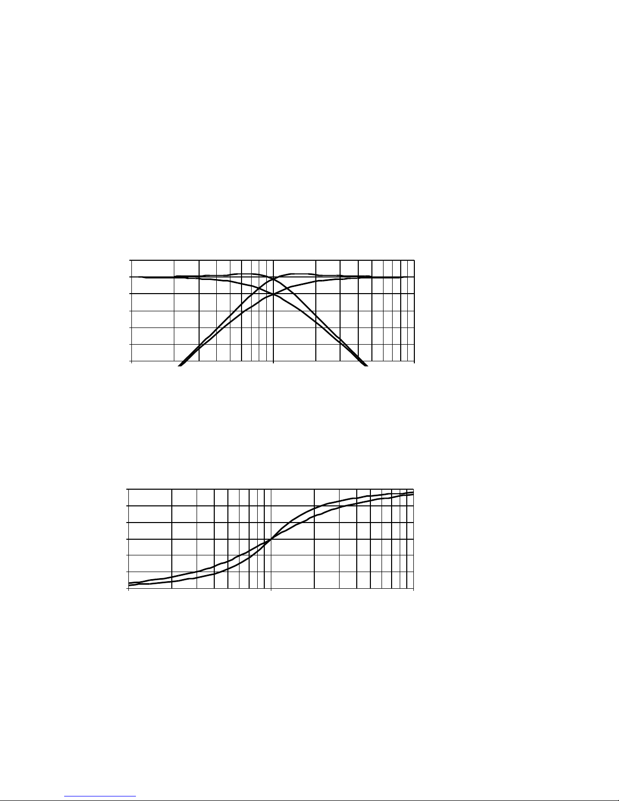
The damping control allows adjusting the frequency response at the crossover point. Figure 6
show the effect of the damping control. The figure shows the frequency response for the
maximum and minimum settings. This control is only available on the XM6 and the XM9. The
XM16 and the XM26 do not have a damping control. The damping control adjusts both high pass
and low pass simultaneously. This control is useful for fine-tuning the room frequency response.
Sometimes it happens that at the crossover point there is a small peak or dip in the frequency
response. This is caused by the fact that at this frequency the sound is produces by both high and
low speakers simultaneously. It is often very hard to hear this dip, but it can easily be seen if a
frequency spectrum analyzer is used.
© 2017 Marchand Electronics Inc. www.marchandelec.com.
6
-50
-40
-30
-20
-10
0
10
10 100 1000
+5 dB
-4 d B
The frequency
response of the
amplitude for tw o
settings of the damping
control.
Figure 6
0
60
120
180
240
300
360
10 100 1000
+5 dB
-4 d B
Frequency response of
the phase for tw o
values of the damping
conrol. The phase for
high pass and low pass
are the same
Figure 7
Page 7
© 2017 Marchand Electronics Inc. www.marchandelec.com.
7
Figure 8
-50
-40
-30
-20
-10
0
10
10 100 1000
The frequency
response of the
amplitude for the XM16
eighth order crossover
network.
Figure 9
0
60
120
180
240
300
360
420
480
540
600
660
720
10 100 1000
Frequency response of
the phase f or the XM16
eighth order crossover
network. The phase for
high pass and low pass
are the same
Page 8
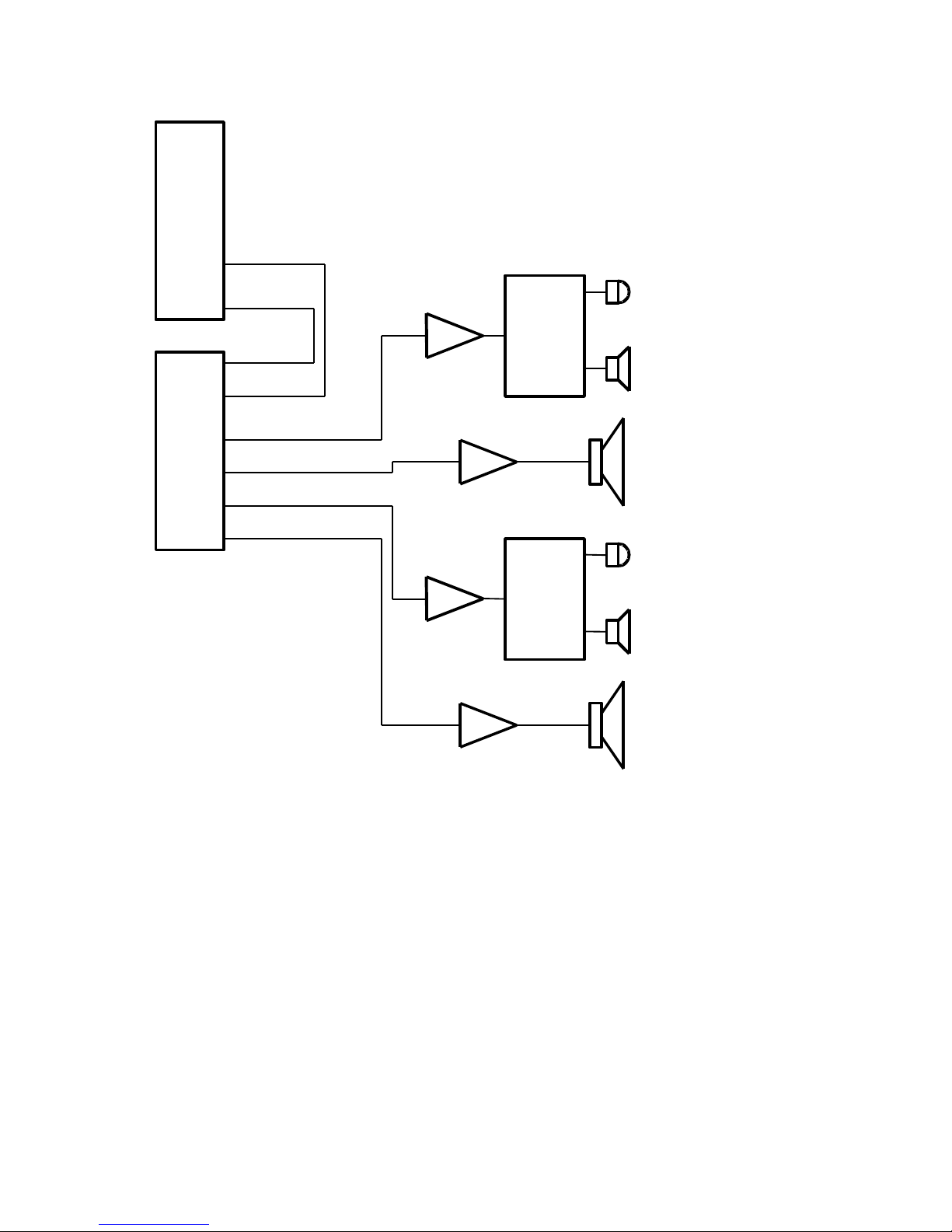
Hybrid system with passive crossover on the highs and active crossover on the lows
© 2017 Marchand Electronics Inc. www.marchandelec.com.
8
Amp
Left
Woofer
C
r
o
s
s
o
v
e
r
Left High Out
Right Low Out
Right High Out
Left Low Out
P
r
e
a
m
p
Right In
Left In
Left Out
Right Out
Left
Mid
Amp
Left
Tweeter
Passive
Crossover
Amp
Right
Woofer
Right
Mid
Amp
Right
Tweeter
Passive
Crossover
Page 9
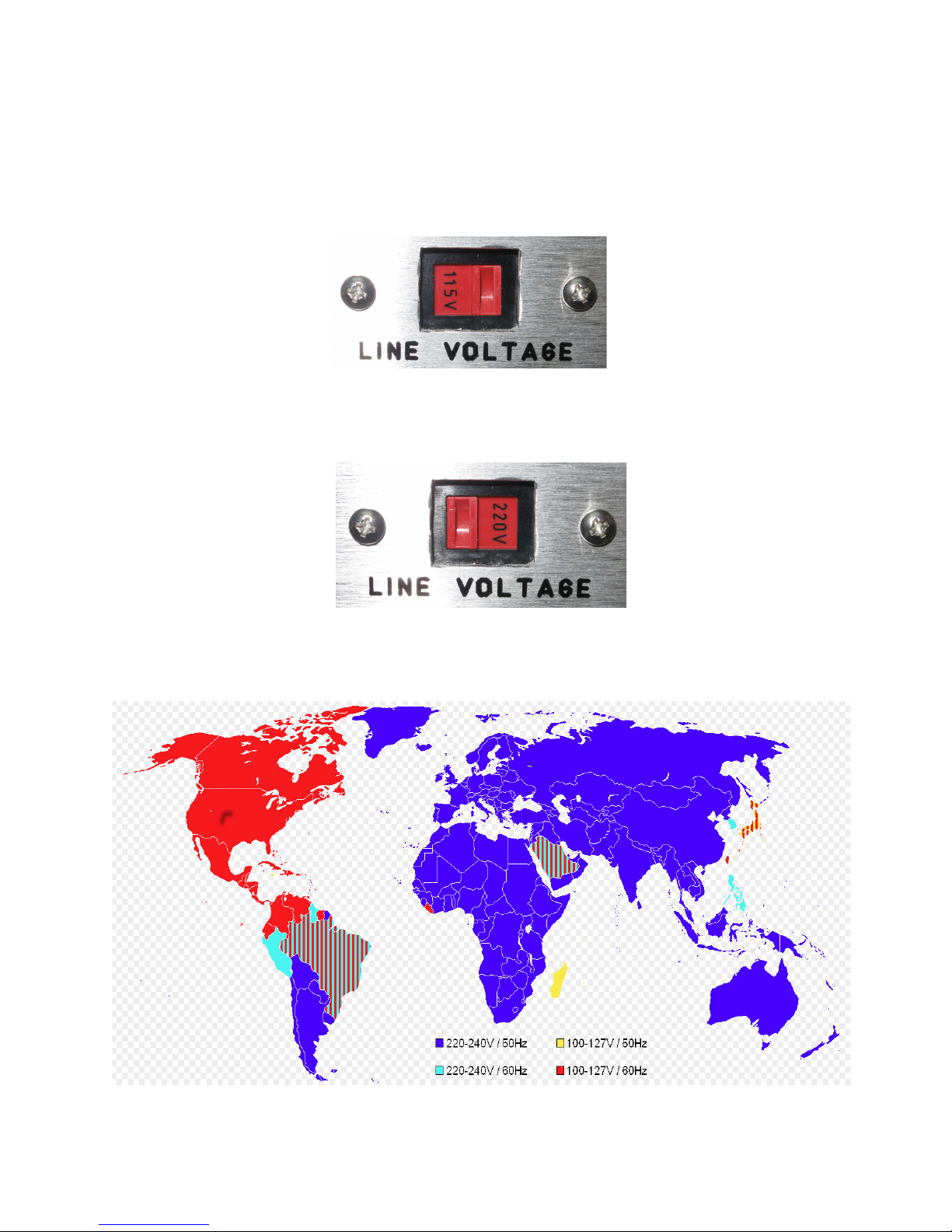
Voltage selector switch
Before switching on the power make sure the power selector switch on the rear is set to the
proper voltage. This is important. The wrong setting may damage the equipment. The crossovers
are compatible with both 50Hz and 60Hz.
Use the 115V setting where the power line voltage is 100V to 127VAC.
This is typical in USA, Canada, Central America and Japan
Use the 220V setting where the power line voltage is 220V to 240VAC.
This is typical in Europe, Africa and most of Asia.
From (c)https://en.wikipedia.org/wiki/File:WorldMap_Voltage%26Frequency.png
© 2017 Marchand Electronics Inc. www.marchandelec.com.
9
 Loading...