

Page 1
Marchand Electronics Inc.
PO Box 473, Webster, NY 14580
Tel:(585) 872-0980 Fax:(585) 872-1960
[email protected] http://www.marchandelec.com
(c)2002 Marchand Electronics Inc.
MB401 300 Watt MOSFET Power Amplifier
500W into 4 Ohm
300W into 8 Ohm
©2001 Marchand Electronics Inc. PO Box 473 Webster NY 14580 (585)872 0980 www.marchandelec.com
1
Page 2
Features
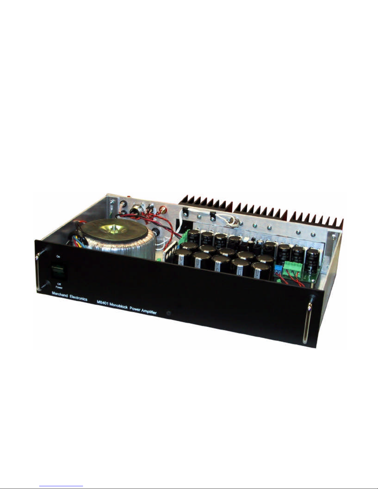
The MB401 is a mono MOSFET power amplifier for high quality audio reproduction. The construction is all heavyduty. The amplifier is housed in an aluminum chassis. Heatsinks on the rear of the unit provide the cooling. Inside
is a toroidal power transformer and power supply with large storage capacitors. The amplifier is designed for use
with a 4 or 8 Ohm load, but it is stable with any output load.
.
XLR Balanced inputs Balanced inputs for high noise immunity
RCA Standard line level inputs
Selector switch Switch between balanced and standard inputs
Binding Posts Connection for the loudspeakers
Fuse Protects the amplifier in case of overload
Thermal cutout Protects the amplifier in case it gets too hot
Power entry connector Standard line cord for 120V AC 1-phase operation.
Specifications.
Frequency response: 20Hz - 20KHz +/- 1 dB
Harmonic Distortion @ 1KHz, 10W 0.02% or better
Sensitivity 1.28VRMS
Voltage gain 32dB(40X)
Input impedance (RCA) 500 KOhm
Short circuit output current 20 A peak, 15A Continuous
Output load 8 or 4 Ohm, stable with any load
Max power output 500W into 4 Ohm, 300W into 8 Ohm
Power requirement 120VAC, 6A fuse; 240 VAC available
Construction All metal cabinet, black with white legend
Dimensions: 17” x3.5” x 11” (WxHxD)
Weight: 22 lbs
MB401 Power Amplifier
Left
Inputs
In Out
Full Range
In in in in in in out
PR41 Preamplifier
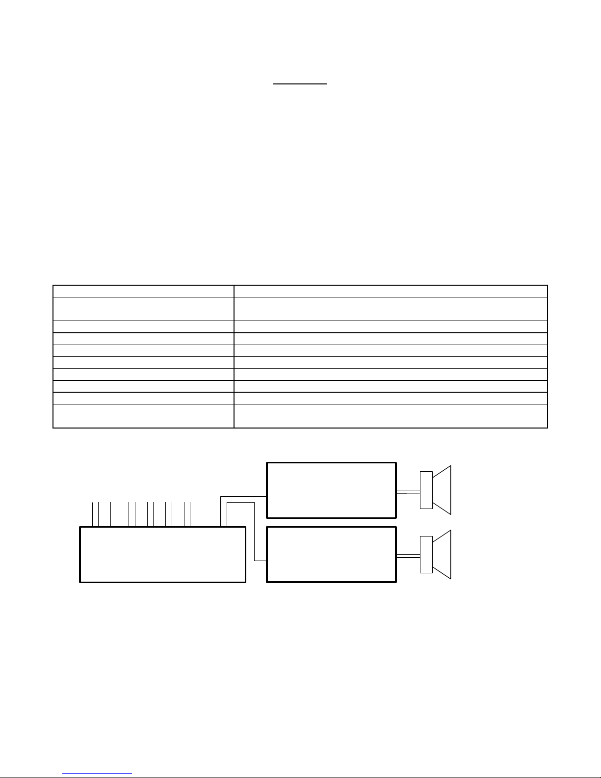
Figure 1 Typical Sound System
©2001 Marchand Electronics Inc. PO Box 473 Webster NY 14580 (585)872 0980 www.marchandelec.com
MB401 Power Amplifier
In Out
Right
2
Page 3
Inputs
MB401 Power Amplifier
In Out
Left
High
In in in in in in out
PR41 Preamplifier
in out hi out lo
Electronic Crossover
XM6, XM9, XM16 or XM26
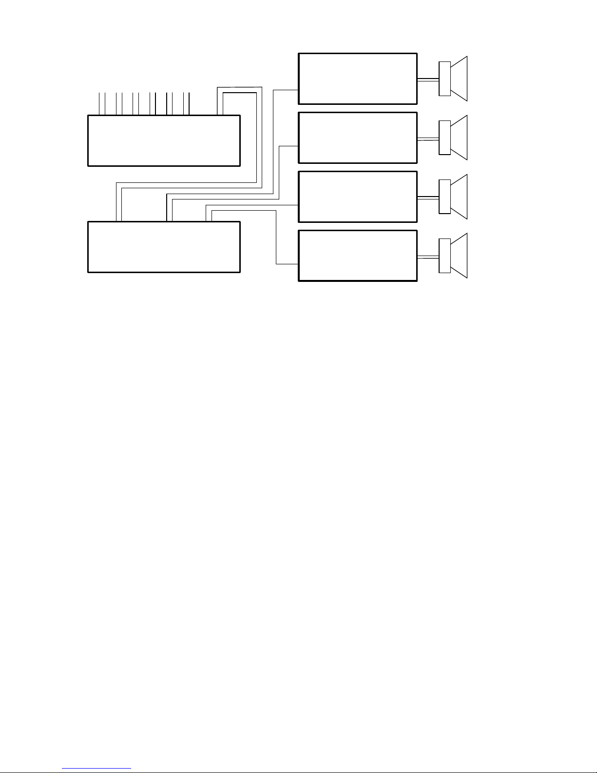
Figure 2 Sound System with 2-way Electronic Crossover Network
MB401 Power Amplifier
In Out
MB401 Power Amplifier
In Out
MB401 Power Amplifier
In Out
Right
Left
Low
Right
©2001 Marchand Electronics Inc. PO Box 473 Webster NY 14580 (585)872 0980 www.marchandelec.com
3
Page 4
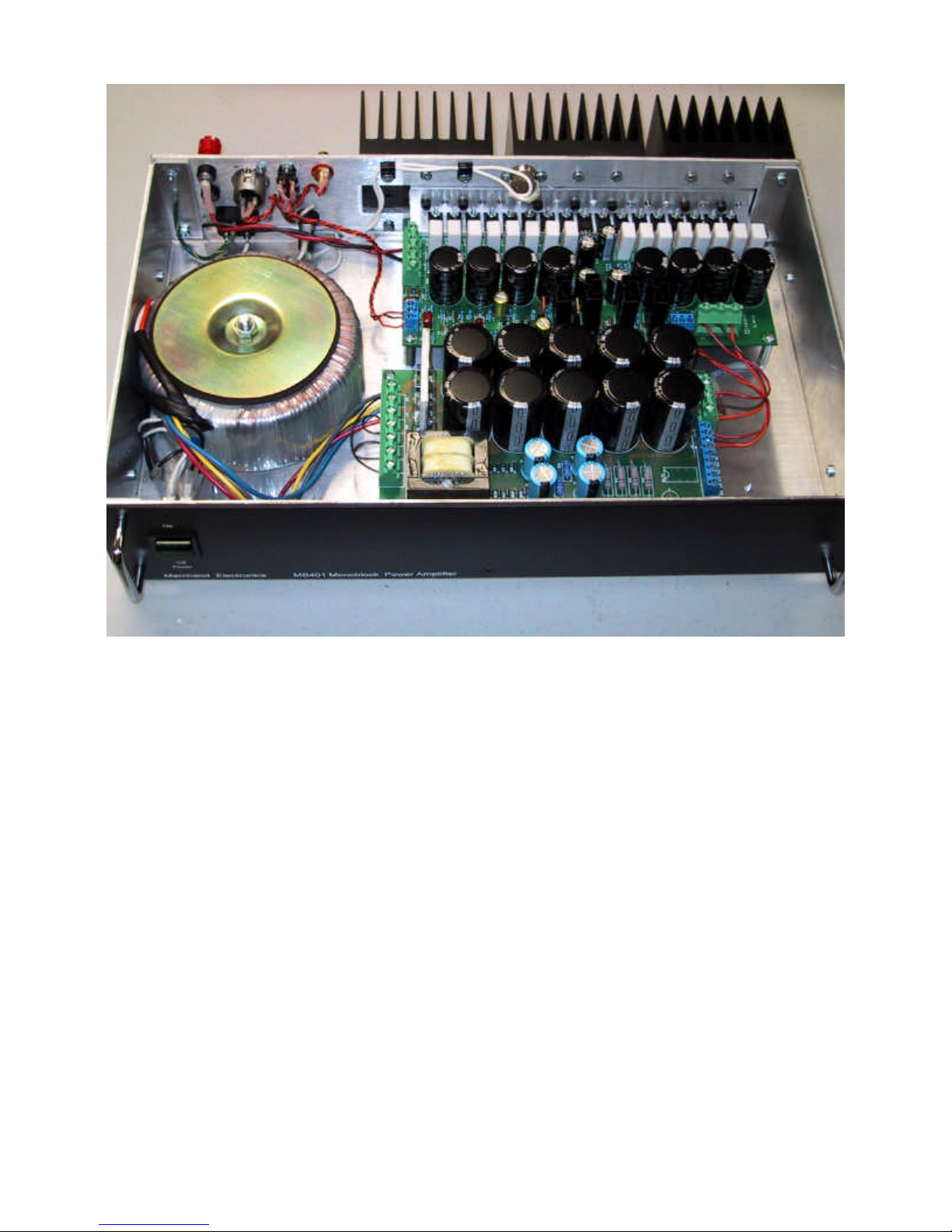
Figure 3: Inside view. Note the placement of the MB401 power amplifier board (mounted on heatsink on the rear
of the unit) and the PS112 power supply board; (mounted onto the bottom of the chassis) . The toroidal power
transformer is mounted near the left of the unit on the baseplate.
©2001 Marchand Electronics Inc. PO Box 473 Webster NY 14580 (585)872 0980 www.marchandelec.com
4
Page 5
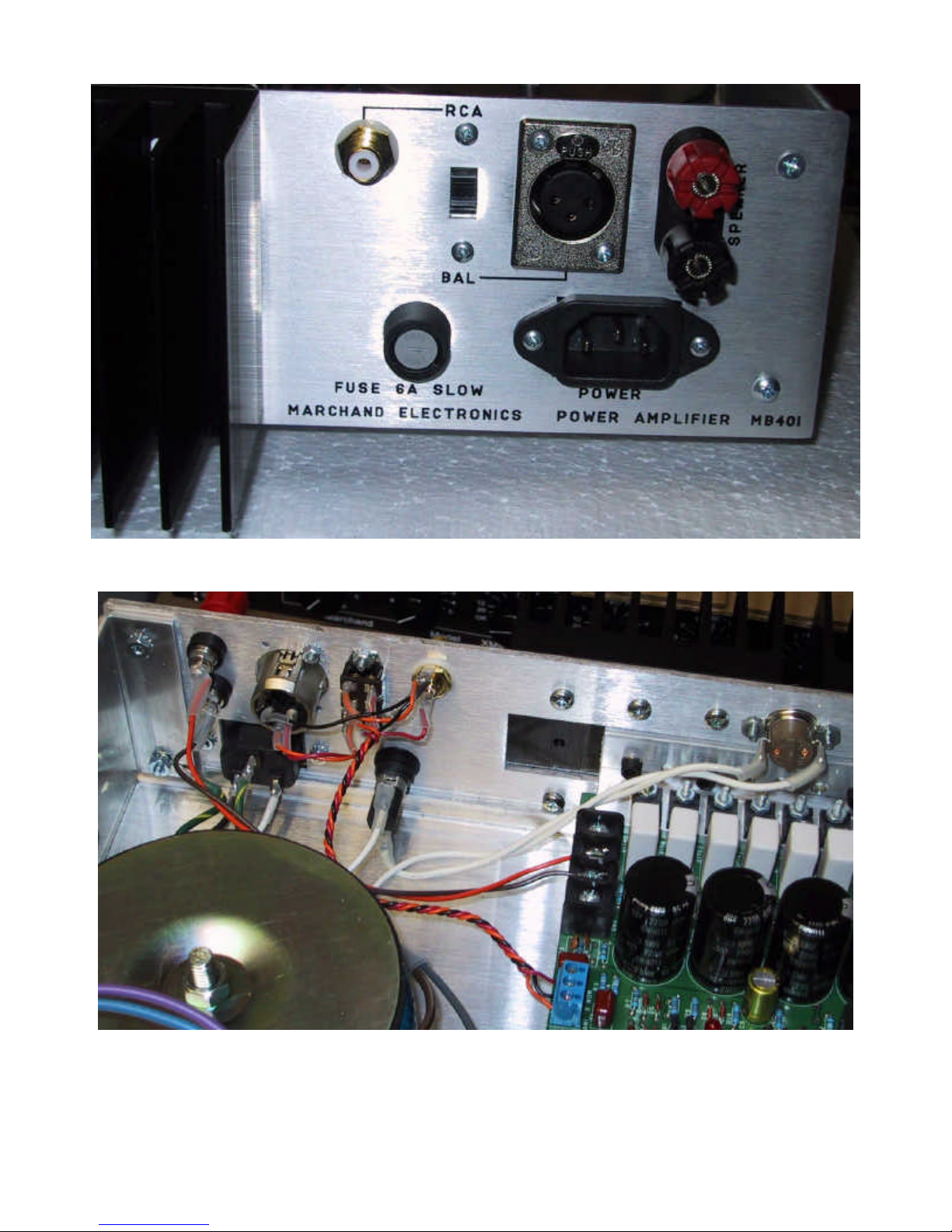
Figure 4 Rear view of the amplifier.
Figure 5 Inside view of the rear panel
©2001 Marchand Electronics Inc. PO Box 473 Webster NY 14580 (585)872 0980 www.marchandelec.com
5
Page 6

Assembly Instructions for the MB401 Kit.
Parts list.
Qu. Description
1 MB401 board assembly
1 PS112 board assembly
1 chassis base
4 rubber feet
4 #6 x ½” selftap
1 front panel
1 front panel spacer
1 rear panel
3 heatsink
2 1.0” standoff
5 0.5” standoff
1 500VA xformer + hardware
1 RCA connector
1 XLR connector
1 fuse holder
1 fuse, 6A slowblow
1 power entry connector
1 speaker terminal connector
1 DPST power on/off switch
1 DPDT slide switch
1 thermal cutout
2 handles
4 6/32 x 5/8” sockethead
1 resistor 2.4KOhm, 2W
2 #6 solder lug
2’ heatshrink 1/8”
1’ heatshrink 1/4”
7 8/32 x 1/2” socket head
16 8/32 x 1/2” panhead
23 #8 split lockwasher
7 6/32 x 3/8” flathead
5 6/32 x 1/2” flathead
1 6/32 x 1/2” black flathead
1 6/32 x 1/2” oval head
7 6/32 x 1/4” panhead
6 #6 kepsnut
5 #6 split lockwasher
6 4/40 x 1/2” panhead
2 4/40 x 1/2” flathead
8 #4 kepsnut
2‘ 22 ga wire brown
2‘ 22 ga wire red
2‘ 22 ga wire orange
2‘ 18 ga wire brown
2‘ 18 ga wire red
2‘ 18 ga wire orange
1/2‘ 22 ga wire green/yellow UL
3‘ 22 ga black UL
3‘ 22 ga white UL
1 heatsink compound
1 line cord
1 Hex L-Key 3/32"
1 Hex L-Key 7/64"
1 Hex L-Key 9/64"
Assembly instructions.
Before assembling the MB401 amplifier complete the
assembly of the MB401 power amplifier board and the
PS111 power supply board.
Rear panel: Remove the rear panel from the cabinet
before starting this assembly. Mount the following
parts to the rear panel:
1 DPDT switch
using 4/40 x 1/2" panhead + kepsnut.
1 XLR connectors
using 4/40 x 1/2" panhead + kepsnut.
1 RCA connectors, .
1 Pair of binding posts
1 Fuse holder
1 Power entry module.
using 4/40 x 1/2" panhead + kepsnut.
1 Thermal cutout
using 4/40 x 1/4" flathead + kepsnut
Now mount the rear panel to the chassis using 5 6/32
x 1/2" flathead screws and kepsnuts. Note that the
chassis bottom has a large hole in the bottom. This
hole is used to mount the transformer. This hole
should be on the left side of the chassis, as seen from
the front.
Now mount the 3 heatsinks to the rear of the chassis.
Make sure all previous steps have been completed
because some screws can not be reached after the
heatsinks have been monted. Use 16 8/32 x 1/2"
screws for this. Do use split lockwashers on all 14
screws.
Front panel: Mount the front panel and front panel
spacer to the chassis using the 4 6/32 x 5/8"
©2001 Marchand Electronics Inc. PO Box 473 Webster NY 14580 (585)872 0980 www.marchandelec.com
6
Page 7
sockethead screws and the handles. Use lockwashers
Rubber washers
Use two of these.
with these screws. Install the fifth screw in the bottom
of the panel. Use a 6/32 black flathead with kepsnut
for this.
Feet: Install the 4 rubber feet in the bottom of the
cabinet using the #6 selftap screws.
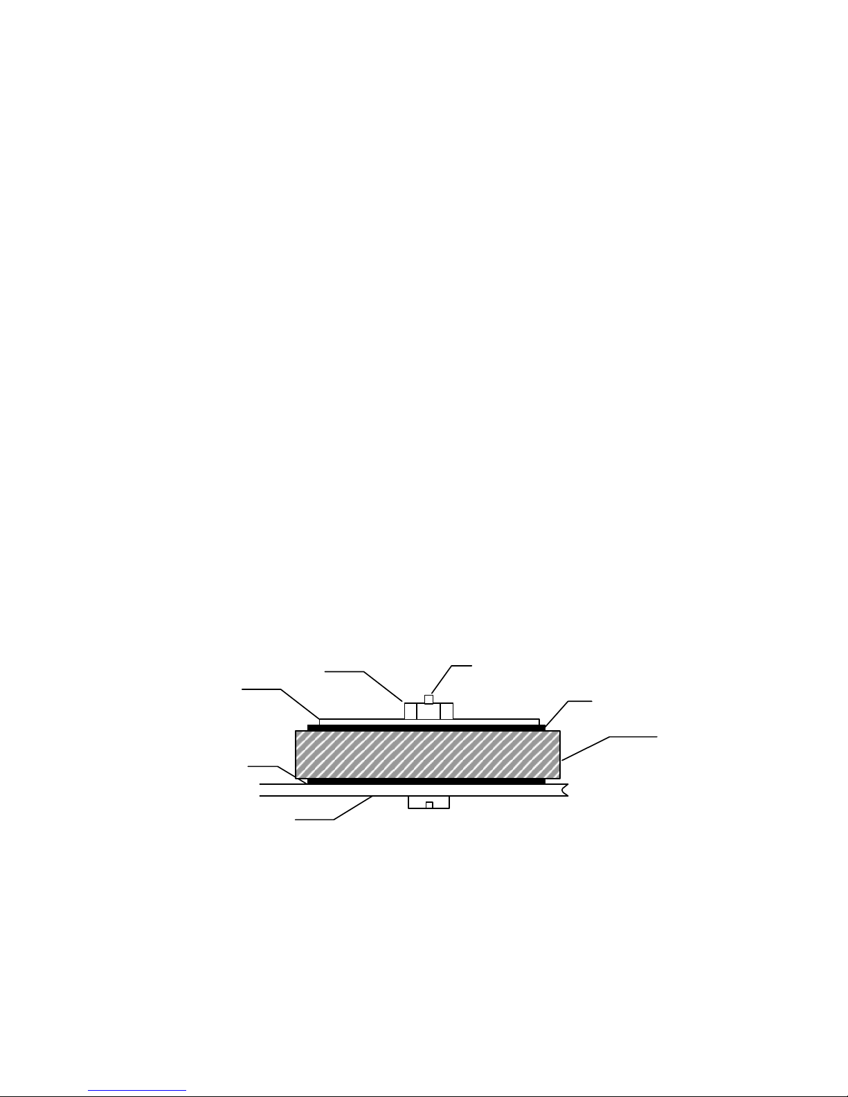
Transformer: Install the transformer. See figure
below.
Chassis grounding. Solder the 2400Ohm, 2W
resistor to a solder lug. Solder a length of black wire
to the other end of the resistor. Install solder lug
under one of the hex standoffs of the MB401 board.
Connect the wire the GROUND connection (terminal
marked G of the three position terminal block) of the
MB401 board. This will connect the chassis of the
amplifier to the DC ground of the power supply.
!!!! Assembly is now complete. !!!!
PS112 Power supply: Install the power supply next
to the power transformer using 5 hex 1/2" standoffs,
as shown in fig x. Use 6/32 x 3/8 flatheads on the
bottom and 6/32 x 1/4" panheads on top.
MB401 power amplifier board: Install the board onto
the heatsink with the 7 8/32 bolts with hex head. Use a
lock washer with each bolt. Access to the mounting
bolts is difficult. Use a long hex-wrench for this.
IMPORTANT: Use heat sink compound to cover the
rear of the MB401 mounting bracket completely
before installing. Locate the board as far to the right
(away from the xformer) as possible. Use the two 1"
hex standoffs to secure the board to the bottom plate.
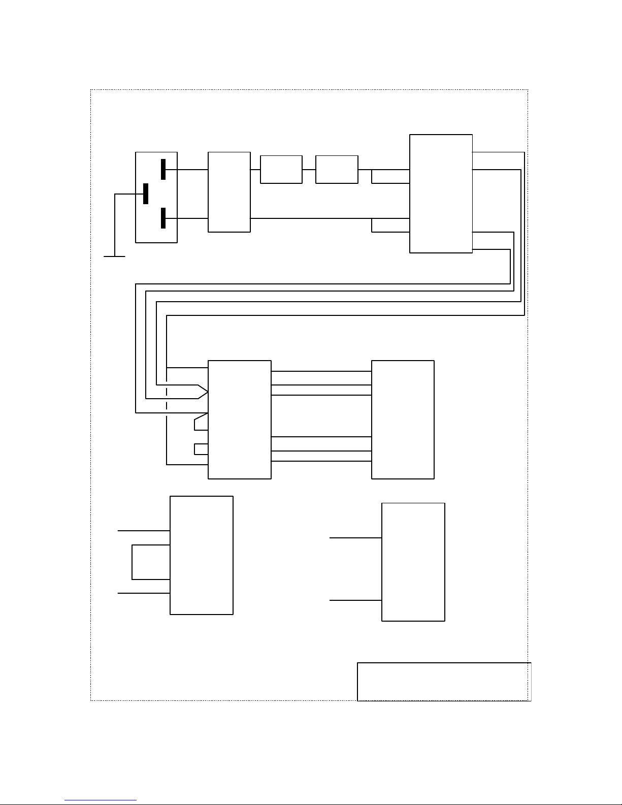
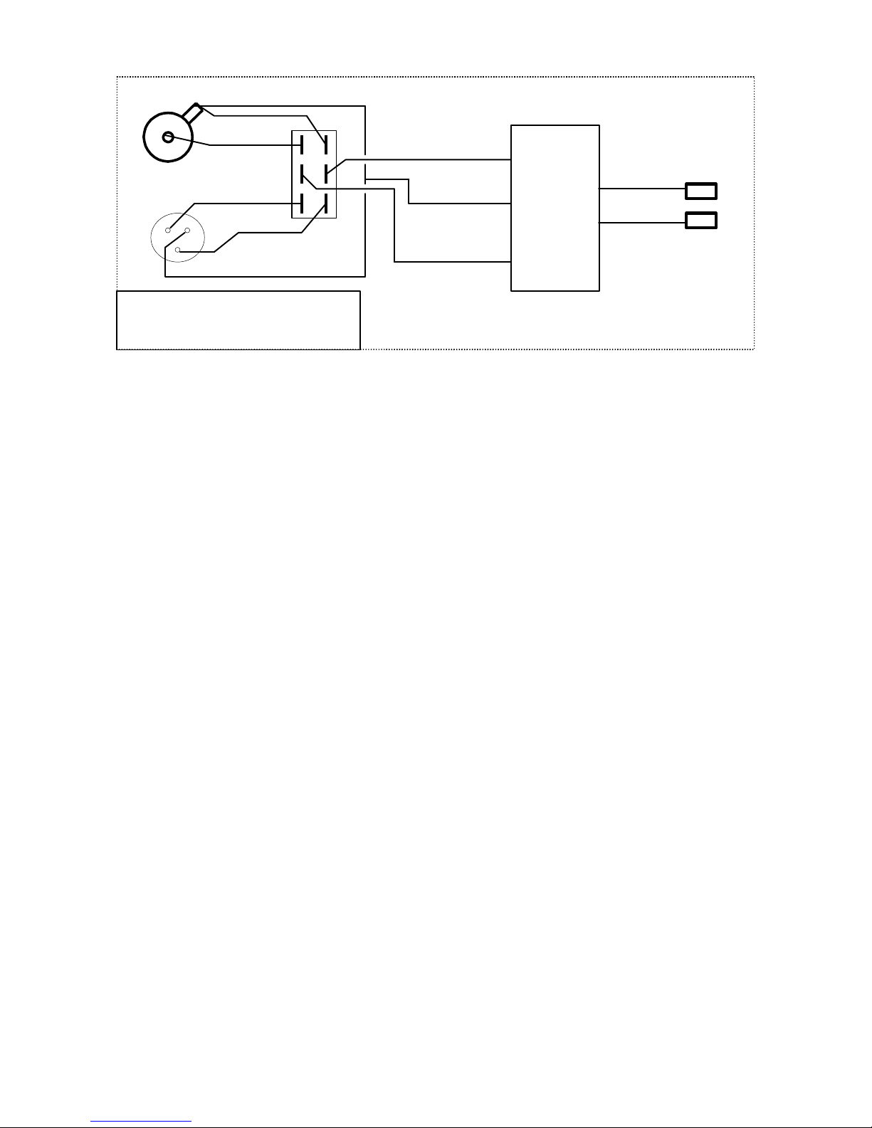
Wiring: Wire up the rear panel according to the circuit
diagram.
Wiring note: Use the #22 wire with the thick insulation
for the AC wiring to and from the power transformer.
Use the #18 wire for the wire to the loudspeaker
terminals and between the PS111 and the MB401
board. Use #22 wire for all other interconnect.
Initial power up.
The first time power is applied observe any unusual
events, like smoke, etc. Turn the power off
immediately if this happens and check for correct
construction. It is best to power up initially using a
variable power transformer (variac) and observe
operation at about half line voltage.
The bias current of the amplifier board now needs to
be adjusted. Connect a DMM between testpoints TP1
and TP2. With no signal on the input and no
loudspeaker connected use R33 to set the bias of the
MB401 main amplifier board to 50mV.
The heatsinks will become warm during normal
operation. When the amplifier is powered up but no
power is delivered the heatsink should become just
slightly warm to the touch. If they become hot in this
mode check the bias current of the MB401 amplifier
module.
With full AC voltage applied the V+ reading should be
approx. 80V (referred to ground), the V- reading -80V,
the V++ reading +92V and the V-- -92V.
Metal Plate
Chassis bottom
Figure 6 : Mounting of power transformer
©2001 Marchand Electronics Inc. PO Box 473 Webster NY 14580 (585)872 0980 www.marchandelec.com
Nut
Bolt
Rubber washer
Transformer
7
Page 8
Red (18)
red
yellow
blue
gray
black
white
Rear Panel
Red
Yellow
Blue
Gray
white
black
orange
brown
black
white
orange
brown
black
black
Red(22)
Power entry
Front
panel
Power
switch
Rear panel
Wire to
Case
Green/
yellow
L
DPDT
switch
Circuit
breaker
w.
light
N
Thermal
cutout
Toroidal
Power
Transformer
*** primary connections
shown for 120V line
AC
CT
V++
GND
V--
AC
PS112
TA
TB
TC
TD
V+
GND
V-
Brown(22)
Orange(22)
Brown(18)
Orange(18)
V++
GND
V--
MB401
V+
GND
V-
Toroidal
Power
Transformer
***connect primary like this for
240V line
©2001 Marchand Electronics Inc. PO Box 473 Webster NY 14580 (585)872 0980 www.marchandelec.com
Toroidal
Power
Transformer
***use black wires with xformer with
single primary
MB401 Power Amplifier
Power wiring
(c)2002 Marchand Electronics Inc.
8
Page 9
inv
GND
non
out
GND
RED
BLK
brown
RCA
G
red
RCA
red
XLR
orange
12
3
brown
MB301 Power Amplifier
Signal Wiring
(c)2000 Marchand Electronics Inc.
IN
2
3
XLR
1
Figure 7 : Rear panel wiring for signal and speaker.
Orange(22)
Brown(22)
Red(22)
MB301
Speaker
Red(18)
Brown(18)
Binding
Posts
Use heavy 18
gauge wire for the
speaker wires only
©2001 Marchand Electronics Inc. PO Box 473 Webster NY 14580 (585)872 0980 www.marchandelec.com
9
Page 10

Assembly instructions for the MB401 main amplifier board.
Parts List
ID Value Description
Resistors
R1 1.00M 1%, 1/4W, Metal Film
R2 1.00M 1%, 1/4W, Metal Film
R3 24.9K 1%, 1/4W, Metal Film
R4 24.9K 1%, 1/4W, Metal Film
R5 1.00M 1%, 1/4W, Metal Film
R6 1.00M 1%, 1/4W, Metal Film
R7 1.00M 1%, 1/4W, Metal Film
R8 10.0K 1%, 1/4W, Metal Film
R9 10.0K 1%, 1/4W, Metal Film
R10 100 Ohm Trimmer Potentiometer
R11 not used
R12 100 K 1%, 1/4W, Metal Film
R13 2.00K 1%, 1/4W, Metal Film
R14 2.00K 1%, 1/4W, Metal Film
R15 2.00K 1%, 1/4W, Metal Film
R16 499 Ohm 1%, 1/4W, Metal Film
R17 499 Ohm 1%, 1/4W, Metal Film
R18 499 Ohm 1%, 1/4W, Metal Film
R19 100 Ohm 1%, 1/4W, Metal Film
R20 499 Ohm 1%, 1/4W, Metal Film
R21 100 Ohm 1%, 1/4W, Metal Film
R22 100 Ohm 1%, 1/4W, Metal Film
R23 Jumper
R24 Jumper
R25 not used
R26 100K 1%, 1/4W, Metal Film
R27 not used
R28 100K 1% ,1/4W, Metal Film
R29 not used
R30* 49.9 Ohm 1%, 1/4W, Metal Film
R31*1 Ohm 5W Wirewound
R32*2.00K 1%, 1/4W, Metal Film
R33 10 K Trimmer Potentiometer
R34* 49.9 Ohm 1%, 1/4W, Metal Film
R35*1 Ohm 5W Wirewound
R36*2.00K 1%, 1/4W, Metal Film
R37 not used
*8 places
Capacitors
C1 1.0uF Stacked Film
C2 1.0uF Stacked Film
C3 1pF Ceramic NPO
C4 1pF Ceramic NPO
C5 47uf, 100v Aluminum Electrolytic
C6 47uf, 100v Aluminum Electrolytic
C7 1000 pF Ceramic Disk
C8 4.7uf, 250v Aluminum Electrolytic
C9 4.7uf, 250v Aluminum Electrolytic
C10* 2200uf, 80v Aluminum Electrolytic,SF
C11 6800uf, 6.3v Aluminum Electrolytic
C12 6800uf, 6.3v Aluminum Electrolytic
C13 6800uf, 6.3v Aluminum Electrolytic
C14 0.22uf Stacked Film
C15 6800uf, 6.3v Aluminum Electrolytic
C16* 2200uf, 80v Aluminum Electrolytic,SF
* 4 places
SF Snap Fit
Diodes
D1 1N4735 6.2 Volt Zener Diode
D2 1N4148 Signal Diode
D3 1N4148 Signal Diode
D4 1N4148 Signal Diode
D5 1N4148 Signal Diode
D6 1N4735 6.2 Volt Zener Diode
D7 LED
D8 1N4148 Signal Diode
D9 1N4148 Signal Diode
D10 not used
D11 Jumper
D12 not used
D13 Jumper
D14 1N4735 6.2 Volt Zener Diode
D15 1N4735 6.2 Volt Zener Diode
D16 HER106 1 Amp. Diode
D17 HER106 1 Amp. Diode
Transistors
Q1* ZVNL120A N-Channel SS MOSFET
Q2* ZVNL120A N-Channel SS MOSFET
Q3 ZVNL120A N-Channel SS MOSFET
Q4 ZVP2120A P-Channel SS MOSFET
Q5 ZVP2120A P-Channel SS MOSFET
Q6 ZVNL120A N-Channel SS MOSFET
Q7 ZVNL120A N-Channel SS MOSFET
Q8 MTP2P50E P-Channel MOSFET
Q9 MTP2P50E P-Channel MOSFET
Q10 IRF710 N-Channel MOSFET
Q11 IRF710 N-Channel MOSFET
Q12 not used
Q13 not used
Q14 2N2222 NPN transistor
Q15 2N2907 PNP transistor
Q16 IRFI640 N-Channel Power MOSFET
Q17** IRFI640 N-Channel Power MOSFET
©2001 Marchand Electronics Inc. PO Box 473 Webster NY 14580 (585)872 0980 www.marchandelec.com
10
Page 11

Q18** IRFI9640 P-Channel Power MOSFET
*Q1,Q2 come as a matched pair
**Q17 & Q18 8 places each matchesd sets
Q9,Q11,Q12,Q13 need heatsink
1 2N2222 NPN transistor
1 2N2907 PNP transistor
* Matched sets of power transistors
Mechanical
The MB401 main board kit contains the
following parts:
Qu. Value Description
Resistors
16 49.9 Ohm 1%, 1/4W, Metal Film
3 100 Ohm 1%, 1/4W, Metal Film
4 499 Ohm 1%, 1/4W, Metal Film
19 2.00K 1%, 1/4W, Metal Film
2 10.0K 1%, 1/4W, Metal Film
2 24.9K 1%, 1/4W, Metal Film
3 100K 1%, 1/4W, Metal Film
5 1.00M 1% ,1/4W, Metal Film
1 100 Ohm Trim Pot, 10 turn
1 10 KOhm Trim Pot, 10 turn
16 1.0 Ohm 5W Wirewound
Capacitors
2 1.0uF Stacked Film
2 1pF NPO Ceramic
1 1000 pF Ceramic Disk
1 0.22uf. Stacked Film
2 4.7uf, 250v Aluminum Electrolytic, R
2 47uf, 100v Aluminum Electrolytic, R
4 6800uf, 6.3v Aluminum Electrolytic, R
8 2200uf, 80v Aluminum Electrolytic, SF
R: radial
SF: snapfit
Diodes
4 1N4735 6.2 Volt Zener Diode
6 1N4148 Signal Diode
2 HER106 High Efficiency Diode
1 LED
Transistors
Quantity Description
2 3 Pos. Terminal block Blue
1 3 Pos. Terminal block Black
1 4 Pos. Terminal block Black
17 4/40x3/4” Machine Screw
17 4/40 Nut
17 #4 flat washer
34 #4 split lockwasher
1 Heat Sink Bracket
2 TO220 heatsink, TALL
1 Bag Heat Sink Compound
1 MB401 circuit board
2 testpoint
Assembly Instructions
Most parts are installed in the usual way. Insert the
part at the location on the circuit board as indicated by
the silk screen identification and solder on the solder
side of the board. Start with installing smaller parts
and install large parts last. This makes installation
easiest. The circuit board has plated through holes, so
parts need only be soldered on the solder side of the
board.
Resistors: The 1% metal film resistors are identified
with colored bands in the usual way. The 1% Metal
film resistors have the following markings:
49.9 Ohm Yellow-White-White-Gold--Brown
100 Ohm Brown- Black -Black-Black--Brown
499 Ohm Yellow-White -White -Black--Brown
2.00 K Red -Black-Black-Brown--Brown
10.0 K Brown-Black-Black- Red --Brown
24.9 K Red-Yellow -White-Red--Brown
100 K Brown-Black-Black-Orange--Brown
1.00 M Brown-Black-Black-Yellow--Brown
The multiturn trimmer resistors should be installed so
that the screw is at the location indicated by the white
square.
1 pair ZVNL120A N-Channel SS MOSFET
3 ZVNL120A N-Channel SS MOSFET
2 ZVP2120A P-Channel SS MOSFET
2 IRF710 N-Channel MOSFET
2 MTP2P50E P-Channel MOSFET
9* IRFI640 N-Channel Power MOSFET
8* IRFI9640 P-Channel Power MOSFET
©2001 Marchand Electronics Inc. PO Box 473 Webster NY 14580 (585)872 0980 www.marchandelec.com 11
Jumpers: Install wire jumper is location J1 and any
other locations as shown in the parts list, using bare
hookup wire. Make sure the bare wire of the jumpers
does not touch the surface of the circuit board.
Capacitors: The Electrolytic capacitors are all radial
type. Be sure to observe polarity markings when
installing. The stacked film capacitors are brown and
have marking 224 for .22 uF and 105 for the 1 uF part.
Page 12
Note: The orientation of caps C11 and C12 is not
Circuit board
4/40 x 1/2”
shown on the circuit board. They should be oriented
the same way as C10 and C16.
Diodes: Diodes are installed in the usual way. Make
sure to observe polarity: the band indicated on the
circuit board must coincide with the band on the
device. The band indicates the cathode.
Transistors: Transistors Q1…Q9, Q14, Q15 are the
small black parts with the three leads. Note that the
black part has a big flat side and a round side. Note
that Q1 and Q2 come as a matched pair in a separate
bag. Make sure to use these in the locations Q1 and
Q2. Install the transistors according to the marking on
the circuit board.
Power transistors Q9 and Q11 are mounted with a
heat sink. Q8 and Q10 need no heatsink.
Power transistors Q16 through Q18 are installed onto
the heat-sink bracket.
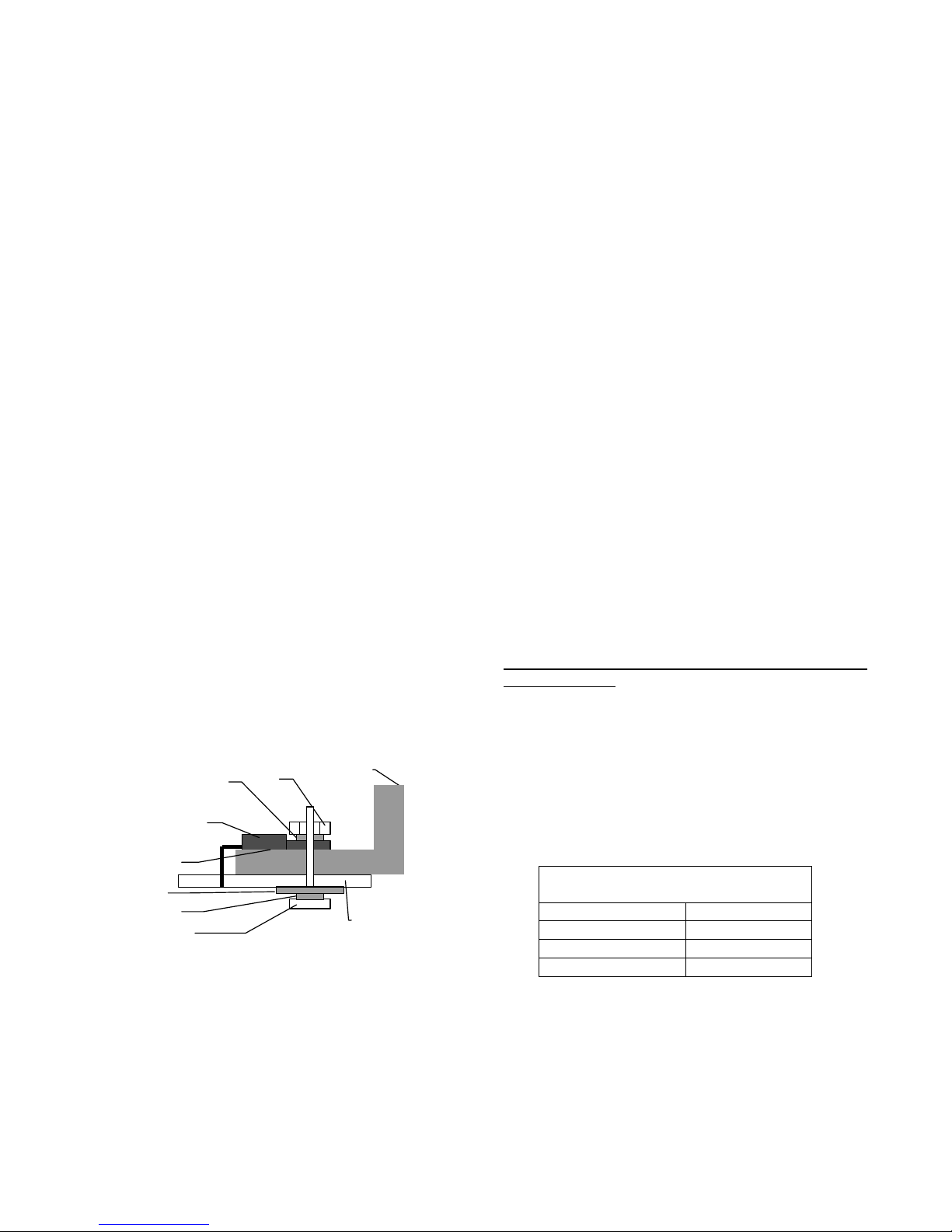
Apply a thin uniform layer of the white silicone
compound on the bottom of each transistor. Install the
transistors with the 4/40 screws, two split lockwashers,
flat washer and nut. See Figure 8. Orient the screws
so that the head of the screw is on the solder side and
the nut is on the component side. Solder the three
transistor pins only after all the mounting screws have
been tightened.
Header: Install the two 1-pin headers at locations TP1
and TP2. These are the testpoint that are used when
adjusting bias.
Terminal Blocks: Install the two small 3-pin and large
3-pin and 4-pin terminal blocks at the edge of the
circuit board.
The bias current of the amplifier must be adjusted by
setting the potentiometer R22. First turn the
potentiometer fully counterclockwise. This will set the
bias current to zero. Hook the MB401 to a bipolar
power supply. The supply voltage should be between
+/- 30V and +/- 60 V. For doing this step it is best to
use a 30V supply. This lower voltage will reduce
chance of damage to the parts if there is an error in
the installation of the parts. It is best to mount the
MB401 onto a large heatsink during testing.
Connect a DVM or suitable voltmeter between the
testpoint TP1 and TP2. If the DMM indicates a voltage
of more than a few mV turn the power off
immediately and check all parts placements. A very
safe way to do this step is to use a variac to increase
the power supply voltage slowly from zero to about
30V, while observing the DMM. Now slowly adjust R33
clockwise until a reading of 15 mV is shown on the
DMM. Precise adjustment is difficult. But a value
between 10 mV and 20 mV is acceptable. Note that
the unit will start heating up a little. The adjustment
should be made when cold. When the amplifier is hot,
the bias current will change a little. This is normal.
Offset adjustment.
The offset voltage of the amplifier must be adjusted by
setting the potentiometer R10. With no signal applied
to the inputs, adjust R10 for minimum DC voltage at
the outputs. A residual output voltage of a few mV is
normal.
The assembly and adjustment of MB401 circuit board
is now complete.
Power supply.
Heat sink bracket
Nut
Heatsink compound
Flat washer
Split lockwasher
Split lockwasher
TO220
MOSFET
Figure 8 Mounting of power transistors.
Assembly is now complete. Take a few minutes to
check all components and orientations. Also make
sure there are no solder bridges.
Bias current adjustment (Class AB) .
©2001 Marchand Electronics Inc. PO Box 473 Webster NY 14580 (585)872 0980 www.marchandelec.com 12
The power supply used is the PS112. It has two
separate sets of outputs, one for the preamp part of
the amplifier board and one set for the output stage.
The preamp voltage is about 20V higher than the
voltage for the output stage.
Output voltages of the PS112
(with 55V transformer)
V+ +80V
V- -80V
V++ +100V
V- - -100V
Page 13
R11
R4
R5
C4
Q11
R30 A,B,C,D,E,F,G,H
C10A,B,C,D
Q16
R17
R10
C11
Q14
C6
C5
R14 D8
C13
C15
R32 A,B,C,D,E,F,G,H
D9
D5
D3
R12
in+
in-
gnd
V++
V--
R15
Q4 Q5
R20
R21
R18
R19
Q8 Q9
R33
C14
on
heatsink
Q6
Q7
R16
C7
D14
D15
D17
R22
D16
R26
Q15
R28
C12
R25
R29
R37
R36 A,B,C,D,E,F,G,H
R34 A,B,C,D,E,F,G,H
R27
Q17A,B,C,D,E,F,G,H
R31 A,B,C,D,E,F,G,H
R35 A,B,C,D,E,F,G,H
Q18 A,B,C,D,E,F,G,H
Q3
R13
R7
D4
D1
D7
Q10
R8
R9
Q1 Q2
D2
D6
V+
out
gnd
V-
C16 A,B,C,D
C3
C2
R3
C1
R1R2
R6
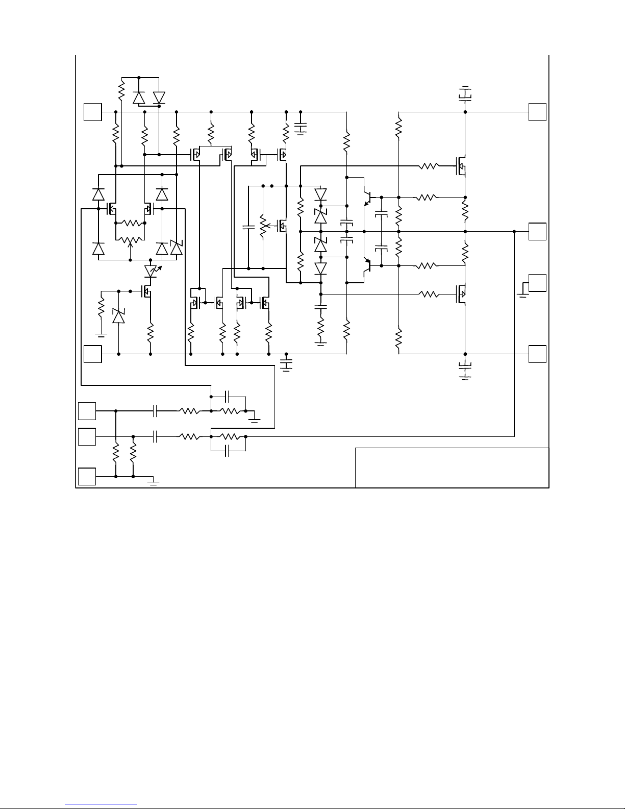
MB401 MOSFET Power Amplifier
(c)2002 Marchand Electronics Inc.
©2001 Marchand Electronics Inc. PO Box 473 Webster NY 14580 (585)872 0980 www.marchandelec.com 13
 Loading...