

Marcegaglia Buildtech Realpont system 75, Tel Dal T5/Uniform system, Realpont system 105 Instruction Manual
Instruction manual
Prefabricated frames

SUPPLY
MATERIAL ZC
REMARKS The weight refers to nominal
Various modes of
supply are available:
• sale
• sale with buyback agreement
• rent
• rent with redemption
All these modes of supply can be
combined with the following services:
• assembly
• disassembly
• service at the building site
hot dip galvanized steel
ZZ
Sendzimir galvanized steel
ZE
electro-galvanized steel
VR
painted steel
TR
tropicalized steel
LG
wood
AL
aluminium
gage values
* Production
on request

Index
REALPONT SYSTEM DESCRIPTION
Prefabricated frames: Realpont system 75
Prefabricated frames: Realpont system 105
Realpont system components
TEL DAL T5/UNIFORM SYSTEM DESCRIPTION
Prefabricated frames: Tel Dal T5/Uniform system
Tel Dal system T5 components
Uniform system components
TUBE-COUPLER SYSTEM DESCRIPTION
Tube-coupler system components 26
04
05
06
14
15
20
INSTRUCTIONS FOR USE
Pre-erection
Erection
Use
Dismantling
Transport
ANCHORAGES
General characteristics
Tie anchorage
Ring anchorage
Screw-down anchorage
Bracing anchorage
Truss beam in tube-coupler anchorage
Anchorage with reinforced rod for reinforced concrete
Anchorage with steel structural plates
ERECTION SEQUENCE
Connection elements
Realpont system erection sequence
30
31
33
34
34
36
37
39
41
41
43
45
46
48
49
CERTIFICATIONS
Certifications
64
Instruction manual • Prefabricated frames
1

Instruction manual • Prefabricated frames
2

Description
Realpont system
Prefabricated frames: Realpont system 75
Prefabricated frames: Realpont system 105
Realpont system components
04
05
06
Instruction manual • Prefabricated frames
3

Prefabricated frames:
Realpont system 75
System with 75 cm frames with bushings
750 mm deep/wide frame • Painted or hot dipped galvanizing protection
Erection of 2500 mm and 3000 mm mixed bay structures • Bushing fittings
SUPPLY
Sales, rent.
UPRIGHTS MATERIAL
- Steel grade S235JR
- Steel tubes: 48.3 mm outside diameter, 2.9 mm S235JRH nominal gage
PROTECTION
- Hot dip galvanized: guaranteed min. coating thickness 55 micron (mean
value);
- Painting performed by immersion with resistance tested to ASTM D
2247-87 moist-room test;
- Col or: red
CHARACTERISTICS
- Bushing fittings;
- Modular bushing fittings to obtain 1.8 m, 2.5 m and 3,0 m mixed bays;
- Safe erection;
- Licensed for uniform building loads of 300 daN/m2 (cl IV, EN12811)
TUBE CHARACTERISTICS ACCORDING TO EN10219
Outside diameter (mm)
Thickness (mm)
2
Section (cm
Moment of inertia (cm
Section modulus (cm
Radius of gyration (cm)
Nominal weight (kg/m)
Ultimate stress (N/mm
Elongation at rupture (%)
Thickness tolerance: ≤ 5%
Tolerance on the mass ± 5% on parts of at least 10 Ton
Other tolerances: as per ISO 65 recommendations
)
4
)
3
)
2
)
48,30 40,00 38,00 38,00 26,90
2,9 2 4 2,5 2
4,14 2,38 4,27 2,78 1,56
10,7 4,32 6,26 4,41 1,22
4,43 2,16 3,29 2,32 0,907
1,61 1,34 1,21 1,25 0,88
3,27 1,87 3,38 2,18 1,24
≥ 360 ≥ 360 ≥ 360 ≥ 360 ≥ 360
≥ 24 ≥ 24 ≥ 24 ≥ 24 ≥ 24
STANDARD DIMENSIONS
Width Span Module
750 mm 1800 mm
2500 mm
3000 mm
2000 mm
Fix height
Manufacturing Standards
- Aut. Min. n.15/0009997/14.03.01.03 del 01/06/2005
- Est. 15/VI/3800/14.03.01.02 del 03/08/2006
- Decreto legislativo 9 Aprile 2008 n. 81
- D.M. 02/09/68
- D.M. 23/03/90 n. 115
- Circolari 44/90 e 156 AA.GG./STC.
- Disciplinare UNICMI sul marchio SQ
Instruction manual • Prefabricated frames
4
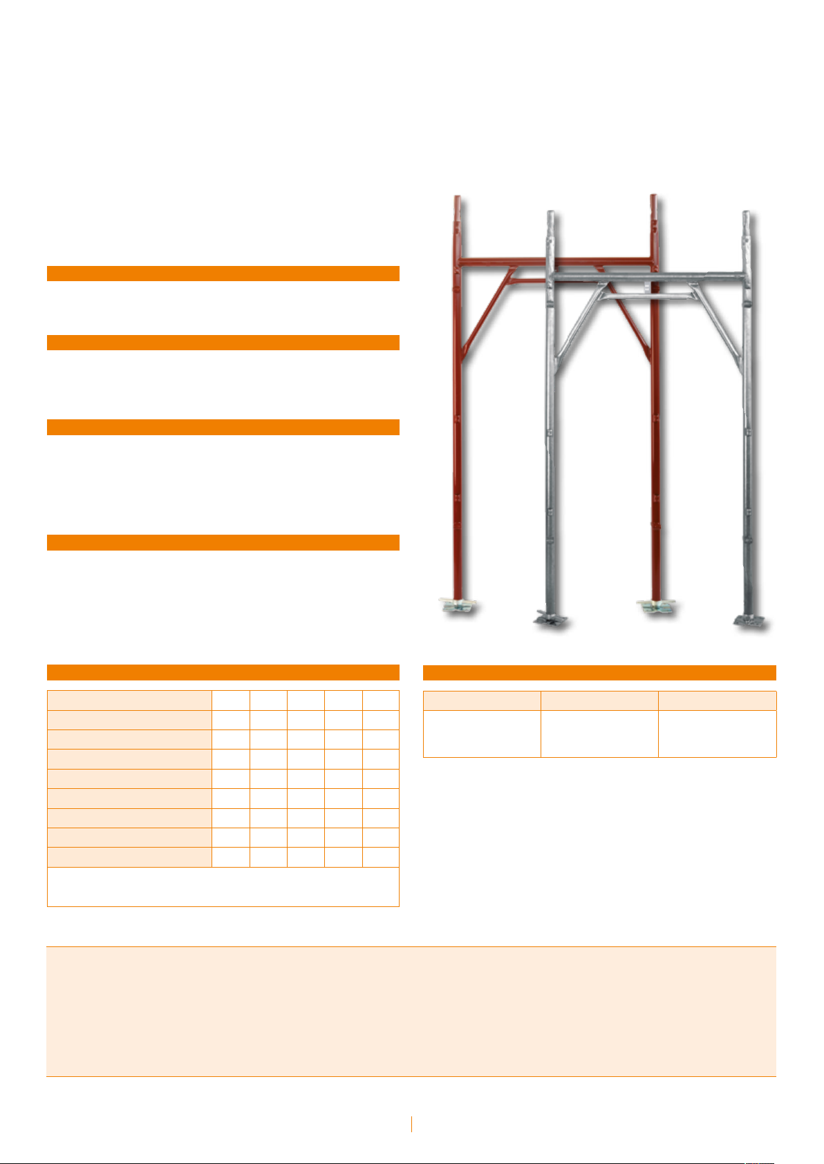
Prefabricated frames:
Realpont system 105
System with 105 cm frames with bushings
Installation of 1050 mm deep working bays • Protection or hot dipped
galvanizing protection • Erection of 2500 mm and 3000 mm mixed bay
structures • Bushing fittings.
SUPPLY
Sales, rent.
UPRIGHTS MATERIAL
- Steel grade S235JR
- Steel tubes: 48.3 mm outside diameter, 2.9 mm S235JRH nominal gage
PROTECTION
- Hot dip galvanized: guaranteed min. coating thickness 55 micron (mean
value);
- Painting performed by immersion with resistance tested to ASTM D
2247-87 moist-room test;
- Col or: red
CHARACTERISTICS
- Bushing fittings;
- Modular bushing fittings to obtain 1.8 m, 2.5 m and 3,0 m mixed bays;
- Safe erection;
- Licensed for uniform building loads of 300 daN/m2 (cl IV, EN12811)
TUBE CHARACTERISTICS ACCORDING TO EN10219
Outside diameter (mm)
Thickness (mm)
2
Section (cm
Moment of inertia (cm
Section modulus (cm
Radius of gyration (cm)
Nominal weight (kg/m)
Ultimate stress (N/mm
Elongation at rupture (%)
Thickness tolerance: ≤ 5%
Tolerance on the mass ± 5% on parts of at least 10 Ton
Other tolerances: as per ISO 65 recommendations
)
4
)
3
)
2
)
48,30 40,00 38,00 38,00 26,90
2,9 2 4 2,5 2
4,14 2,38 4,27 2,78 1,56
10,7 4,32 6,26 4,41 1,22
4,43 2,16 3,29 2,32 0,907
1,61 1,34 1,21 1,25 0,88
3,27 1,87 3,38 2,18 1,24
≥ 360 ≥ 360 ≥ 360 ≥ 360 ≥ 360
≥ 24 ≥ 24 ≥ 24 ≥ 24 ≥ 24
STANDARD DIMENSIONS
Width Span Module
1050 mm 1800 mm
2500 mm
3000 mm
2000 mm
Fix height
Manufacturing Standards
- Aut. Min. Realpont 15/0006649/14.03.01.01 del 12/04/2005
- Est. 15/VI/3799/14.03.01.01 del 03/08/2006
- EU 92 15/0009998/14.03.01.03 del 01/06/2005
- Decreto legislativo 9 Aprile 2008 n. 81
- D.M. 02/09/68
- D.M. 23/03/90 n. 115
- Circolari 44/90 e 156 AA.GG./STC.
- Disciplinare UNICMI sul marchio SQ
- n. 15/VI/3974/14.03.01.02 del 3 agosto 2006
- n. 15/VI/7369/14.03.01.02 del 5 maggio 2008
Instruction manual • Prefabricated frames
5
Realpont system - Components
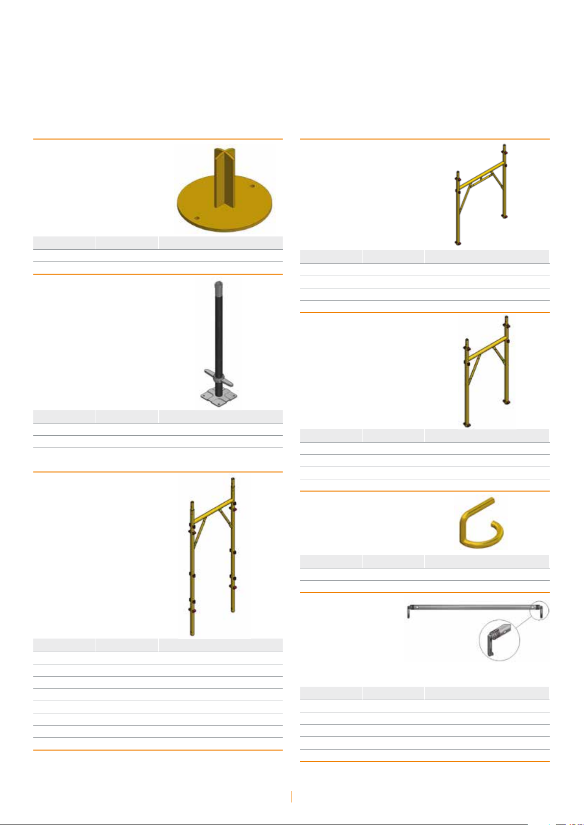
Base plate
mm
48 TR IT/EN 3030100006 0,92
material
cod daN
Adjustable base jack
mm
355 ZE IT/EN 3040800902 2,49
700 ZE IT/EN 3060300141 3,30
1000 ZE IT/EN 3040501012 4,69
material
cod daN
Realpont frame
Realpont half-frame
mm
1050x1300 VR IT 3040105980 15,04
1050x1300 ZC IT 3040105981 15,08
1050x1300 ZC EN 3040105991 15,99
material
cod daN
Realpont compensation-frame
mm
750x1300 VR IT 3040106130 13,17
750x1300 ZC IT 3040106131 13,90
750x1300 ZC EN 3040105961 14,50
material
cod daN
mm
750x2000 VR IT 3040106100 18,14
750x2000 ZC IT 3040106101 19,24
750x2000 ZC EN 3040106071 19,31
1050x2000 VR IT 3040106000 20,10
1050x2000 VR EN 3040107000 20,32
1050x2000 ZC IT 3040106001 21,13
1050x2000 ZC EN 3040107001 21,13
material
cod daN
Spigot pin
mm
100 TR IT/EN 3040701006 0,12
material
cod daN
Guardrail with forged
connection devices
mm
1800 VR IT 3040201010 2,76
1800 ZZ IT/EN 3040201015 2,88
2500 ZZ IT/EN 3040201175 5,80
3000 ZZ EN 3040201705 6,69
material
cod daN
Instruction manual • Prefabricated frames
6

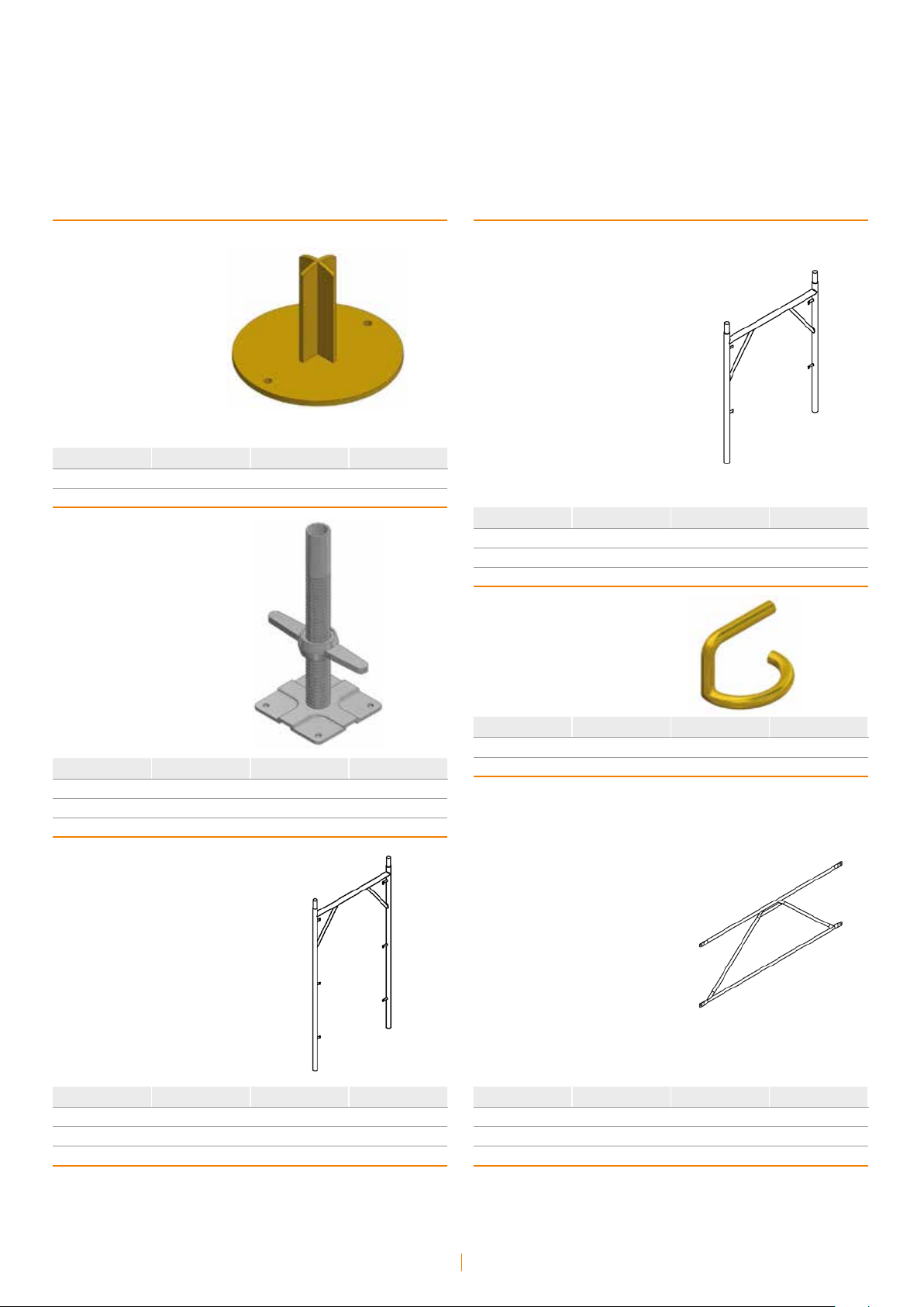
Horizontal-diagonal
brace
Horizontal-diagonal brace
for pedestrian walk-thru frame
with forged connection device
mm
748x1800 VR IT 3040206160 2,86
748x1800 ZZ IT 3040206165 3,33
748x2500 ZZ IT 3040206175 5,94
748x3000 ZZ EN 3040201725 6,87
1048x1800 VR IT/EN 3040206010 3,12
1048x1800 ZZ IT/EN 3040206015 3,26
1048x2500 ZZ IT/EN 3040201195 6,23
1048x3000 ZZ EN 3040201715 7,05
material
cod daN
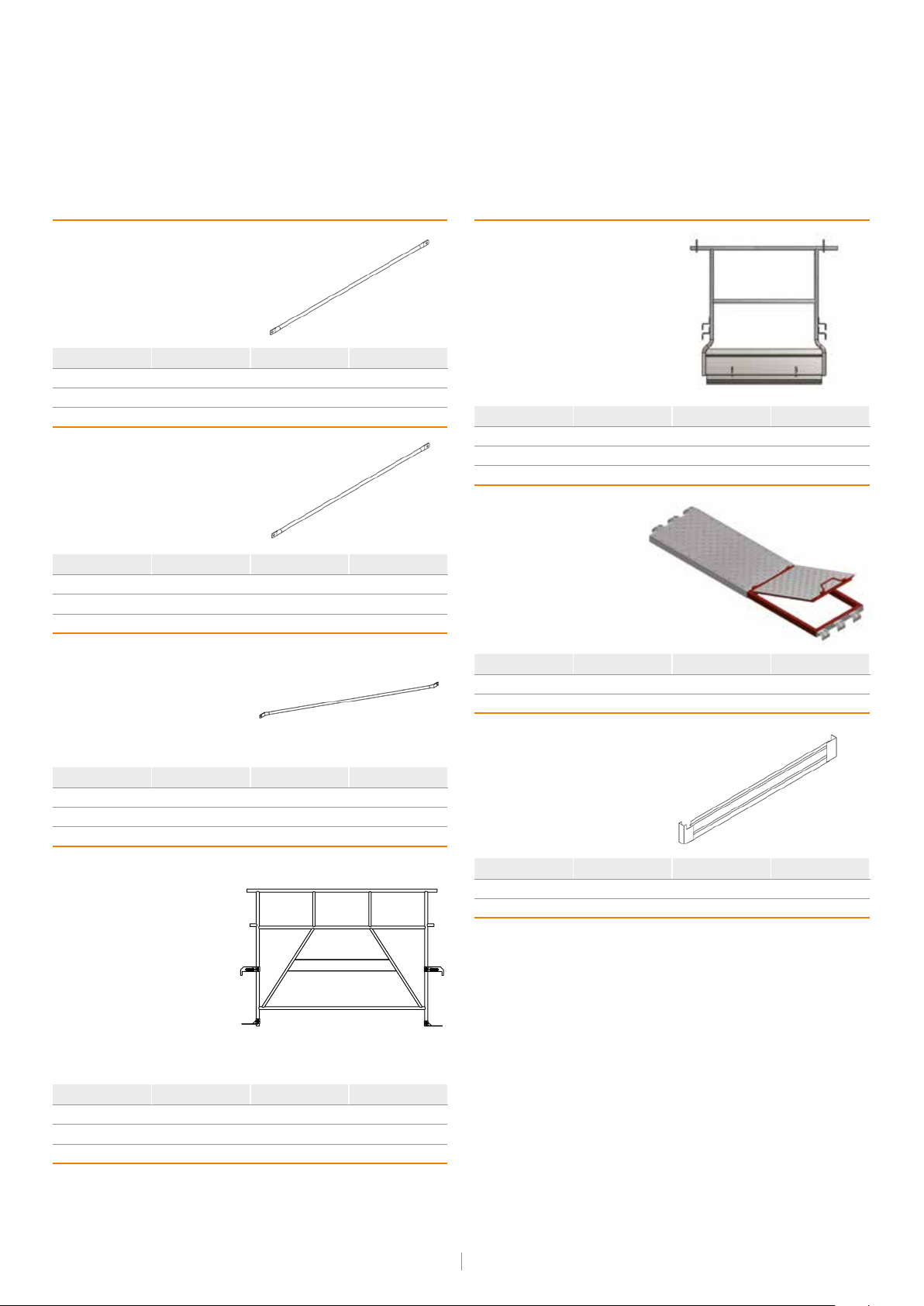
Horizontal-diagonal brace
for tapered ends
with forged
connection devices
mm
348x1800 ZZ IT 3040202065 2,93
348x2500 ZZ IT 3040201165 5,85
648x1800 ZZ 3040201266 3,03
648x2500 ZZ IT 3040201155 5,88
material
cod daN
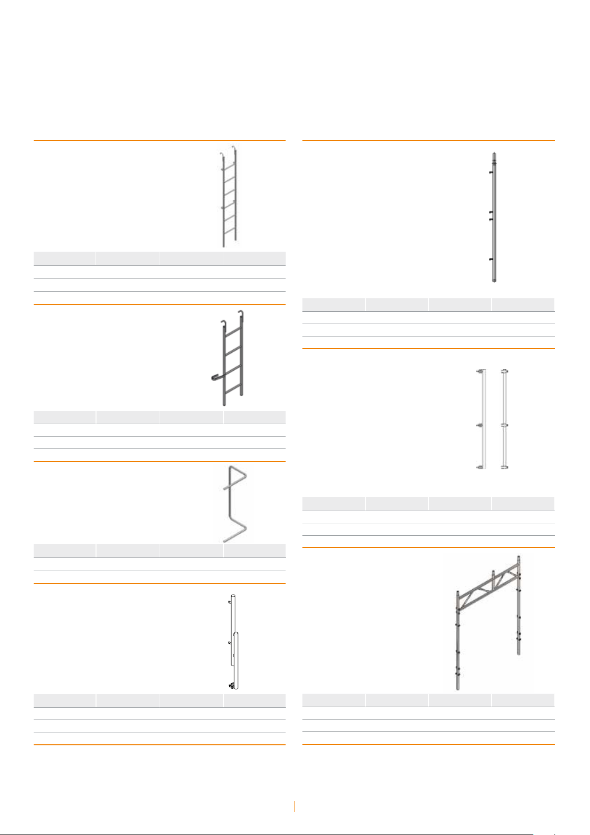
mm
1798x3000 ZZ EN 3040201745 7,68
material
cod daN
Vertical-diagonal brace
mm
1800 VR IT 3040201000 3,25
material
cod daN
Vertical-diagonal
brace with forged
connection devices
mm
1800 ZZ IT 3040201005 3,40
2500 ZZ IT 3040201185 6,40
2500 ZZ EN 3040201195 6,23
3000 ZZ EN 3040201715 7,05
material
cod daN
Double fencing
structure
mm
1800 VR IT 3040201900 9,10
1800 ZC IT 3040201901 10,09
1800 ZC EN 3040201791 8,85
2500 ZZ IT 3040201911 15,08
2500 ZC EN 3040201801 15,42
3000 ZC EN 3040201851 18,80
Instruction manual • Prefabricated frames
7
material
cod daN
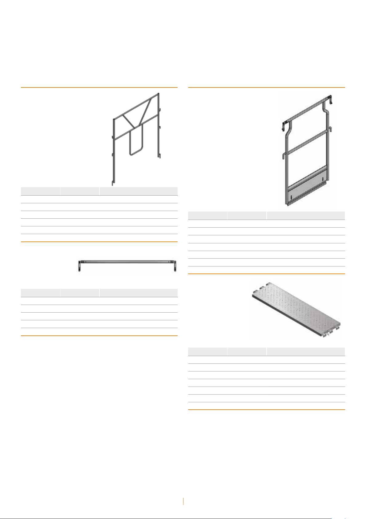
Steel denitive
guardrail frame
Side fencing structure
with toeboard
mm
750 ZC EN 3040201691 14,08
1050 ZC EN 3040201681 15,10
1800 ZC EN 3040201661 16,98
2500 ZC EN 3040201671 18,74
3000 ZC EN 3040201751 21,96
material
cod daN
Transom
mm
750 VR IT 3040206180 1,16
750 ZZ IT 3040206185 1,66
1050 VR IT 3040206060 1,94
1050 ZZ IT 3040206065 2,02
material
cod daN
mm
750 VR IT 3040206040 8,25
750 ZC EN 3040206141 8,67
750 ZC IT 3040206041 9,37
1050 VR IT 3040206100 10,75
1050 ZC EN 3040206131 10,82
1050 ZC IT 3040206101 11,23
material
cod daN
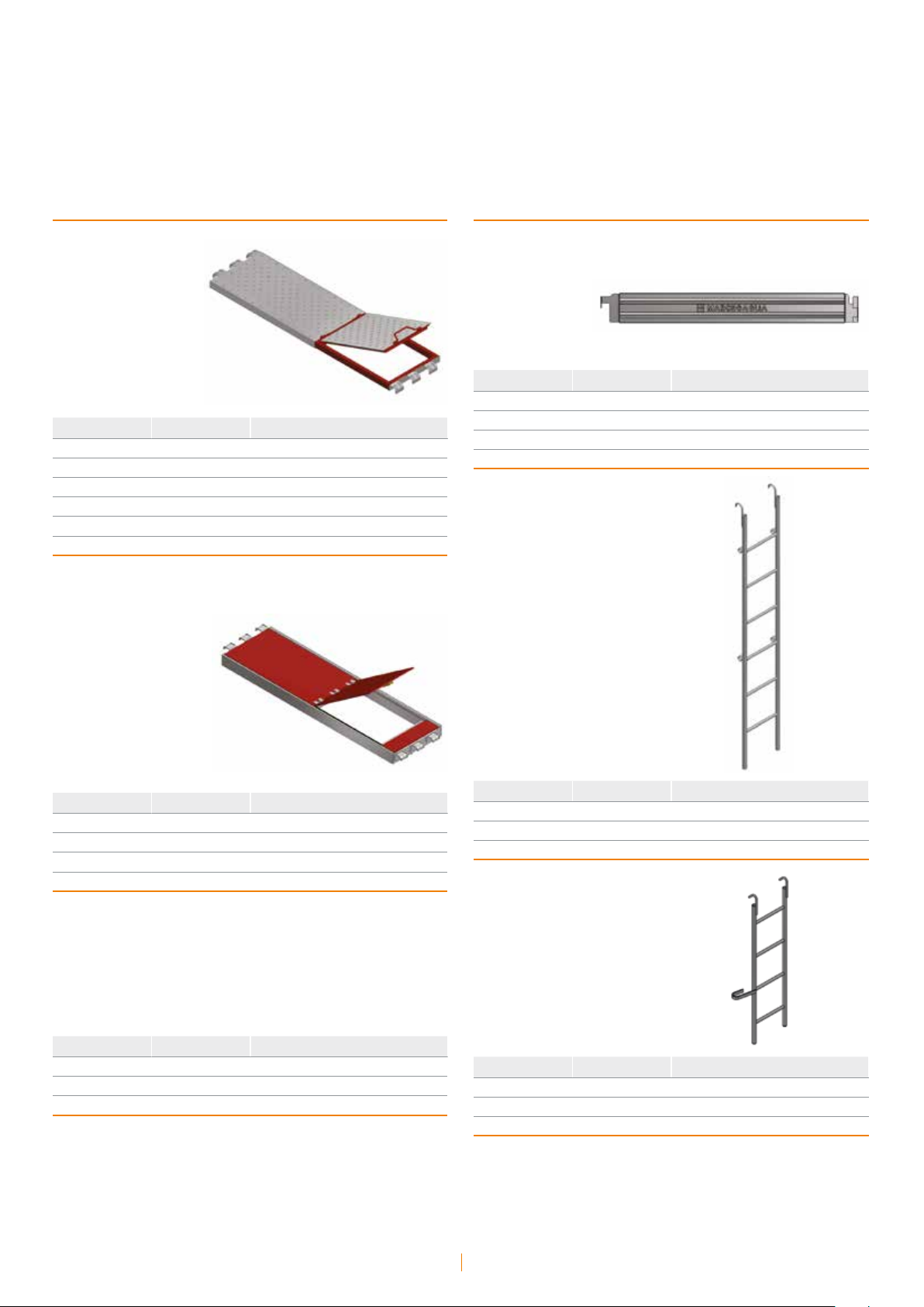
Securdeck scaffold
steel plank
mm
1800x330x50 ZZ IT/EN 3070102041 10,80
2500x330x50 ZZ IT/EN 3070102051 14,38
3000x330x50 ZZ IT/EN 3070102161 16,75
3000x330x75 ZZ IT/EN 3070102071 19,90
1800x490x50 ZZ IT/EN 3070102011 15,16
2500x490x50 ZZ IT/EN 3070102021 21,30
material
cod daN
Instruction manual • Prefabricated frames
8
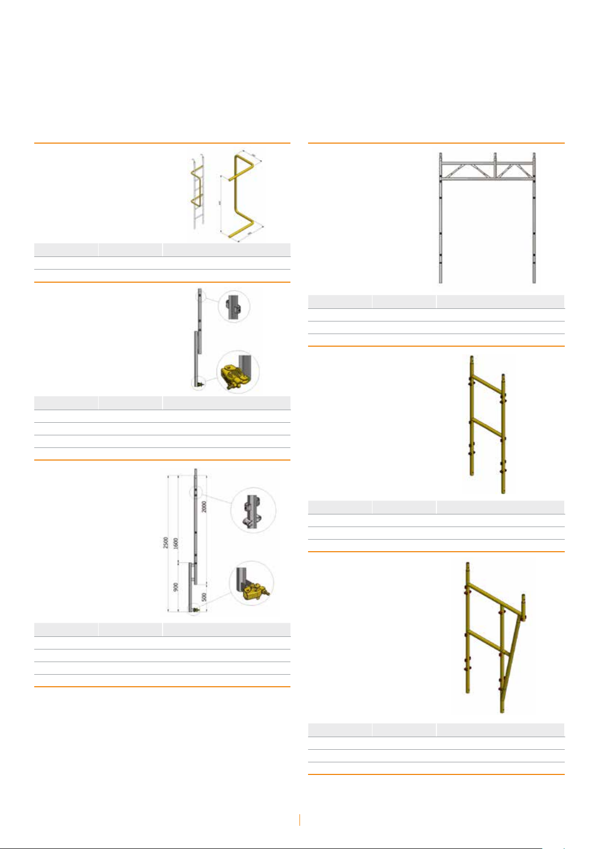
Steel plank
with trapdoor
Toeboard
mm
1800x490x50 PZ 3070100011 28,68
1800x490x50 ZZ 3070100031 28,68
2500x490x50 ZZ 3070800031 38,41
1800x660x60 ZZ 3150200191 35,04
2500x660x60 ZZ 3150200201 45,38
material
cod daN
Aluminium-plywood plank
with frontal opening trapdoor
mm
1800x660 AL 3070101149 20,63
2500x660 AL 3070101139 26,35
3000x660 AL 3070101521 31,53
material
cod daN
mm
1800 ZC 3070200001 5,02
2500 ZC 3070200051 7,35
3000 ZC 3070200071 7,321
material
cod daN
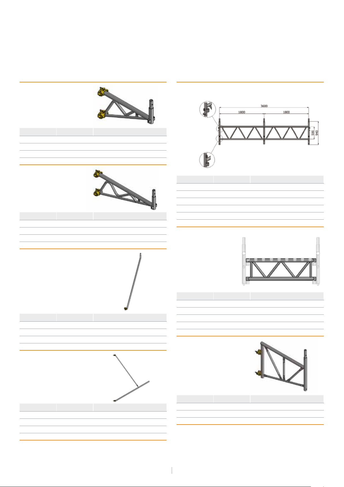
Ladder
mm
2000 VR 3070300130 6,05
2000 ZC 3070300131 7,35
material
cod daN
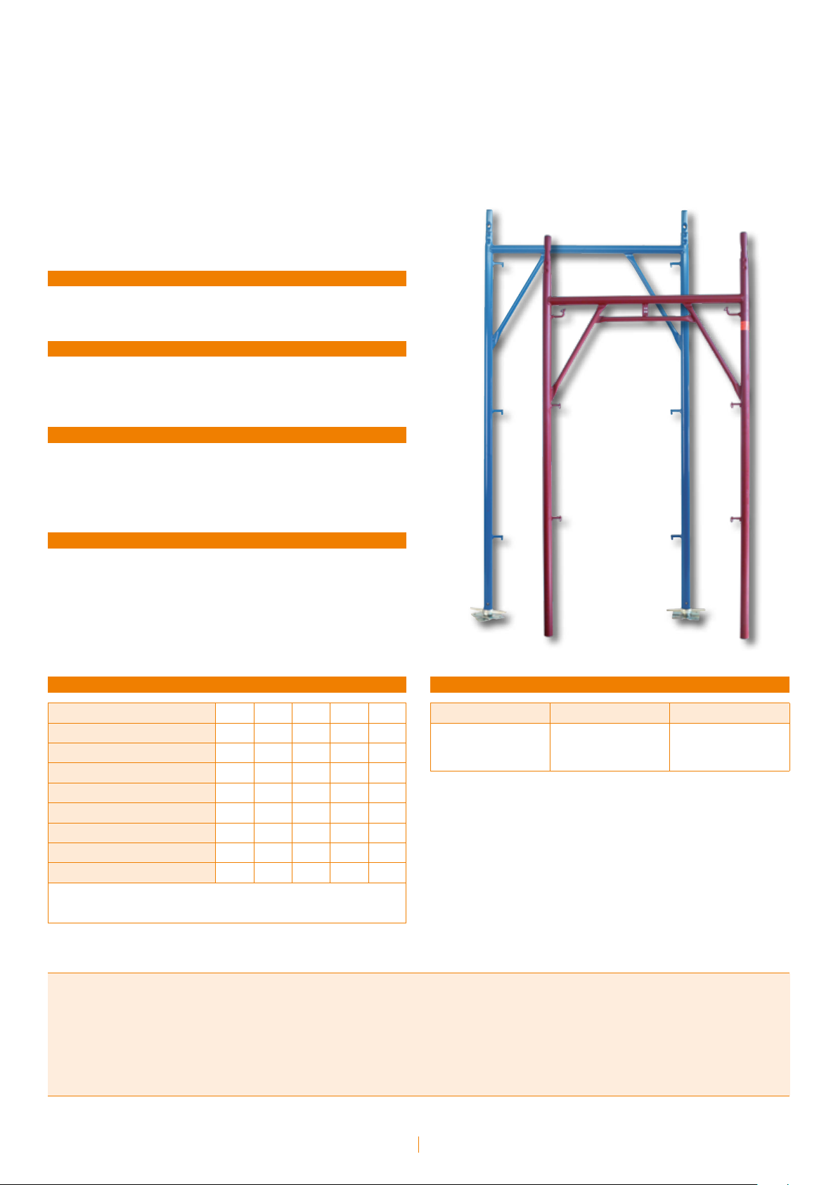
Compensation frame ladder
Aluminium-plywood plank
with frontal opening trapdoor and ladder
mm
2500x660 AL IT/EN 3070101129 32,38
3000x660 AL EN 3070101069 38,06
material
cod daN
mm
1330 VR 3070300160 6,05
1330 ZC 3070300161 7,35
Instruction manual • Prefabricated frames
9
material
cod daN
Ladder handrail
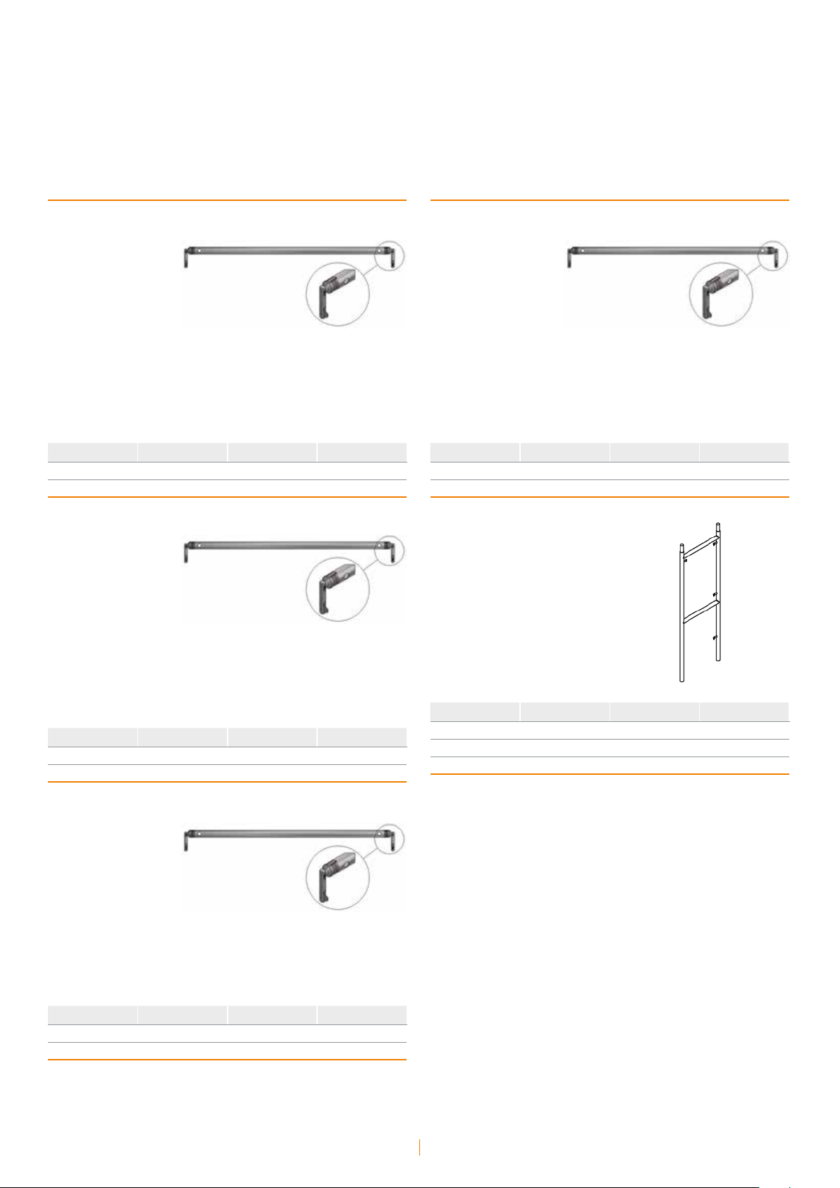
Walk-thru frame
mm
- ZC 3070300141 2,78
material
cod daN
Simple reinforced terminal
mm
- VR IT 3040404080 7,15
- ZC IT 3040404081 7,84
- ZC EN 3040303021 7,84
material
cod daN
Top guardrail upright
mm
1796x2516 ZC IT 3040104081 33,68
1796x2400 ZC EN 3040104051 34,14
material
cod daN
Lower support
mm
- VR IT 3040101030 18,21
- ZC IT 3040101031 19,66
material
cod daN
mm
2000 VR IT 3040404090 11,82
2000 ZC IT 3040404091 12,36
2000 ZC EN 3040404111 12,36
material
cod daN
Upper support
mm
650x1050 VR IT 3040106020 25,93
650x1050 ZC IT 3040106021 27,10
Instruction manual • Prefabricated frames
10
material
cod daN
Bracket
for Realpont system 75
Bridging ledger
mm
750 ZC IT 3040306031 6,54
750 VR IT 3040306030 6,82
750 ZC EN 3040307501 7,01
material
cod daN
Bracket
for Realpont system 1050
mm
1050 VR IT 3040306000 8,50
1050 ZC IT 3040306001 7,98
1050 ZC EN 3040307201 8,58
material
cod daN
Bracket brace
mm
750 ZC IT/EN 3040306041 8,30
1050 VR IT/EN 3040305010 8,44
1050 ZC IT/EN 3040305011 8,73
material
cod daN
Street protection fan
mm
3600 VR IT 3040604020 41,84
3600 ZC IT/EN 3040604021 43,50
5000 ZC IT/EN 3040601031 52,82
5400 VR IT 3040604040 60,66
5400 ZC IT/EN 3040604041 63,06
material
cod daN
Bridging ledger junction
mm
748 ZC EN 3040603021 10,78
748 ZC IT 3040606011 5,63
1048 VR IT/EN 3040605010 8,47
1048 ZC IT 3040605011 8,95
material
cod daN
Bracket
for loading
platform
mm
- VR IT 3040301050 9,19
- ZC IT 3040301051 9,65
- ZC EN 3040800401 18,60
material
cod daN
mm
1048 VR IT 3040306900 13,01
1048 ZC IT/EN 3040306901 13,46
Instruction manual • Prefabricated frames
11
material
cod daN

Instruction manual • Prefabricated frames
12

Description
Tel Dal T5/Uniform system
Prefabricated frames: Tel Dal T5/Uniform system
Tel Dal system T5 - Components
Uniform System - Components
14
15
20
Instruction manual • Prefabricated frames
13
Prefabricated frames:
Tel Dal T5/Uniform system
System with 105 cm frames with pawl
1050 mm deep/wide frame • Painted protection by immersion • Erection
of 1800 mm mixed bay structures • Pawl fittings
SUPPLY
Sales, rent.
UPRIGHTS MATERIAL
- Steel grade S235JR
- Steel tubes: 48.3 mm outside diameter, 2.9 mm nominal gage
PROTECTION
- Painting performed by immersion with resistance tested to ASTM D
2247-87 moist-room test;
- Color: blue for Tel Dal T5, red for Uniform
CHARACTERISTICS
- Pawl fittings;
- Span: 1,8 m;
- Safe erection;
- Licensed for uniform building loads of 300 daN/m
2
(cl. IV, EN 10811)
TUBE CHARACTERISTICS ACCORDING TO EN10219
Outside diameter (mm)
Thickness (mm)
2
Section (cm
Moment of inertia (cm
Section modulus (cm
Radius of gyration (cm)
Nominal weight (kg/m)
Ultimate stress (N/mm
Elongation at rupture (%)
Thickness tolerance: ≤ 5%
Tolerance on the mass ± 5% on parts of at least 10 Ton
Other tolerances: as per ISO 65 recommendations
)
4
)
3
)
2
)
48,30 40,00 38,00 38,00 26,90
2,9 2 4 2,5 2
4,14 2,38 4,27 2,78 1,56
10,7 4,32 6,26 4,41 1,22
4,43 2,16 3,29 2,32 0,907
1,61 1,34 1,21 1,25 0,88
3,27 1,87 3,38 2,18 1,24
≥ 360 ≥ 360 ≥ 360 ≥ 360 ≥ 360
≥ 24 ≥ 24 ≥ 24 ≥ 24 ≥ 24
DIMENSIONS
Width Span Module
1050 mm 1800 mm 2000 mm
Fix height
Manufacturing Standards
- Aut. Min. n.19647/PR-7/B-9 del 10/03/1978
- Aut. Min. n.23455/OM-4 del 04/02/1998
- Decreto legislativo 9 Aprile 2008 n. 81
- D.M. 02/09/68
- D.M. 23/03/90 n. 115
- Circolari 44/90 e 156 AA.GG./STC.
Instruction manual • Prefabricated frames
14
Tel Dal system T5 - Components
Base plate
mm material cod. daN
48 TR 3030100006 0,92
Adjustable base jack
Half-frame Tel Dal T5
mm material cod. daN
1330x1050 VR 3040104010 14,26
1330x1050 ZC 3040104011 14,30
Spigot pin
mm material cod. daN
330 ZE 3040501062 2,42
1000 ZE 3040501012 4,69
Frame Tel Dal T5
mm material cod. daN
2000x1050 VR 3040104000 18,83
2000x1050 ZC 3040104001 19,00
mm material cod. daN
10 TR 3040701006 0,12
Double guardrail P22
mm material cod. daN
- VR 3040204030 7,42
- ZC 3040204031 8,00
Instruction manual • Prefabricated frames
15
Ledger P11
mm material cod. daN
- VR 3040204020 2,42
- ZC 3040204021 2,76
Vertical-diagonal brace
mm material cod. daN
- VR 3040204000 2,99
- ZC 3040204001 3,06
Side fencing structure
with toeboard T5
mm material cod. daN
- VR 3040206120 12,05
- ZC 3040206121 12,39
Steel plank
with trapdoor
Horizontal-diagonal brace
mm material cod. daN
- VR 3040204050 2,68
- ZC 3040204051 2,60
Aluminium temporary
guardrail frame
mm material cod. daN
1048 AL 3040201919 12,33
1800 AL 3040201879 12,85
mm material cod. daN
1800x500x50 ZZ 3070100011 28,68
Toeboard
mm material cod. daN
1800x500 ZZ 3070100001 18,29
Instruction manual • Prefabricated frames
16
Ladder
Upright TD4
mm
2000 VR 3070300130 6,05
2000 ZC 3070300131 7,35
material
cod. daN
Compensation frame ladder
mm material cod. daN
1330 VR 3070300160 3,96
1330 ZC 3070300161 4,15
Ladder handrail
mm material cod. daN
- VR 3040404020 7,07
- ZC 3040404021 7,42
Reinforcement upright RP12
mm material cod. daN
2000 VR 3040406030 8,26
2000 ZC 3040406031 8,58
mm material cod. daN
- ZC 3070300141 2,78
Top guardrail
upright Tel Dal
mm material cod. daN
- VR 3040404000 7,84
- ZC 3040404001 7,29
Walk-thru frame
mm material cod. daN
- VR 3040104060 32,16
- ZC 3040104061 33,68
Instruction manual • Prefabricated frames
17
Guardrail ledger
for walkthrough passage
with forged
connection device
Vertical-diagonal brace
for walkthrough passage
with forged
connection device
mm material cod. daN
- ZZ 3040204105 4,26
Horizontal-diagonal brace
for walkthrough passage
with forged
connection device
mm material cod. daN
- ZZ 3040204125 5,84
Horizontal-diagonal brace
for walkthrough passage
with cold-pressed
connection device
mm material cod. daN
- ZZ 3040204115 5,03
Lower support Tel Dal
mm material cod. daN
- VR 3040104040 17,70
- ZC 3040104041 18,90
mm material cod. daN
- VR 3040204120 5,44
Instruction manual • Prefabricated frames
18
Upper support Tel Dal
mm material cod. daN
- VR 3040104030 25,32
- ZC 3040104031 26,25
Inside bracket
mm material cod. daN
330 VR 3040304050 4,29
330 ZC 3040304051 4,43
Street protection fan
mm material cod. daN
- VR 3040301050 9,19
- ZC 3040301051 9,65
Bridging ledger
Bracket for non axial piers
mm material cod. daN
1050 VR 3040304060 7,76
1050 ZC 3040304061 7,98
Bracket brace
mm material cod. daN
1050 VR 3040304070 8,63
1050 ZC 3040304071 8,93
mm material cod. daN
3600 VR 3040604000 24,39
3600 ZC 3040604001 25,08
Joists junction
mm material cod. daN
- VR 3040604010 5,60
- ZC 3040604011 5,78
Instruction manual • Prefabricated frames
19
Uniform System - Components
Base plate
mm material cod. daN
48 TR 3030100006 0,92
Adjustable base jack
Half-frame Uniform
mm material cod. daN
1330x1050 VR 3040102010 14,79
Spigot pin
mm material cod. daN
10 TR 3040701006 0,12
Side fencing truss Uniform
mm material cod. daN
330 ZE 3040501062 2,42
1000 ZE 3040501012 4,69
Frame Uniform
mm material cod. daN
2000x1050 VR 3040102000 19,73
mm material cod. daN
- VR 3040402020 8,15
Ledger Uniform
mm material cod. daN
- VR 3040202010 2,27
Instruction manual • Prefabricated frames
20

Vertical and
horizontal-diagonal brace
Uniform
Steel plank
with trapdoor
mm material cod. daN
- VR 3040202000 2,68
Transom Uniform
mm material cod. daN
- VR 3040202030 1,82
Side fencing structure
with toeboard Uniform
mm material cod. daN
- VR 3040202040 8,58
mm
1800x490x50 ZZ 3070100011 28,68
material
cod. daN
Toeboard
mm
1800x200 ZZ 3070200001 5,02
material
cod. daN
Ladder
mm material cod. daN
2000 VR 3070300130 6,05
2000 ZC 3070300131 7,35
Aluminium temporary
guardrail frame
mm
1800 AL 3040201919 12,33
material
cod. daN
Instruction manual • Prefabricated frames
21

Compensation frame ladder
mm material cod. daN
1330 VR 3070300160 3,96
1330 ZC 3070300161 4,15
Top end
double element Uniform
mm material cod. daN
- VR 3040402010 9,00
Ladder handrail
mm material cod. daN
2000 ZC 3070300141 2,78
Top guardrail
upright Uniform
Lower support Uniform
mm material cod. daN
- VR 3040102030 17,10
Upper support Uniform
mm
- VR 3040402000 7,15
material
cod IT daN IT
mm material cod. daN
- VR 3040102020 24,95
Instruction manual • Prefabricated frames
22

Bracket for non axial
piers Realpont/Uniform
mm material cod. daN
1050 VR 3040306000 8,50
1050 ZC 3040306001 8,82
Bridging ledger
mm material cod. daN
3600 VR 3040604000 24,39
3600 ZC 3040604001 25,08
5400 VR 3040601020 50,70
5400 ZC 3040601021 52,32
Bracket brace
mm material cod. daN
1050 VR 3040306010 8,44
1050 ZC 3040306011 8,73
Street protection fan
Bridging ledger junction
mm material cod. daN
1050 VR 3040605010 8,47
1050 ZC 3040605011 8,95
mm material cod. daN
- VR 3040301050 9,19
- ZC 3040301051 9,65
Instruction manual • Prefabricated frames
23

Instruction manual • Prefabricated frames
24

Description
Tube-coupler system
Tube-coupler system - Components 26
Manufacturing standards
- Aut. Min. 15/VI/2702/14.03.01.01 del 12/02/2009
- Est. 15/VI/11535/14.03.01.02 del 24/06/2009
- UNI EN 74, EN 39
- Decreto legislativo 9 Aprile 2008 n. 81
- Disciplinare UNICMI sul marchio SQ
Instruction manual • Prefabricated frames
25

Tube-coupler system - Components
Base plate
mm material cod. daN
48 TR 3030100006 0,92
Adjustable base jack
4-bolts right
angle coupler
mm material cod. daN
- TR 3020300006 1,42
- TR 3020300032 1,35
Simple 4-bolts coupler
mm material cod. daN
355 ZE 3040800902 2,49
1000 ZE 3040501012 4,69
2-bolts right
angle coupler
mm material cod. daN
- TR 3020600006 0,88
mm material cod. daN
- TR 3020200006 1,93
Swivel coupler
mm material cod. daN
- TR 3020400006 1,45
Instruction manual • Prefabricated frames
26

Pivot coupler
Pin
mm material cod. daN
- TR 3020000006 1,73
Simple coupler
mm material cod. daN
- TR 3020500006 0,69
Head coupler
mm material cod. daN
- ZC 3030000001 0,63
Anchoring screw
mm material cod. daN
- - 3030200000 1,68
Steel caster
mm material cod. daN
- TR 3020100006 0,94
Scaffold tube S235JR
mm material cod. daN
- ZZ 3010800035 3,45/ml
mm material cod. daN
- VR 3030300000 10,00
Instruction manual • Prefabricated frames
27

Instruction manual • Prefabricated frames
28

Instructions for use
Pre-erection
Erection
Use
Dismantling
Transport
30
31
33
34
34
Instruction manual • Prefabricated frames
29

Pre-erection
CHECKING THE TECHNICAL DOCUMENTATION
e documentation described in the following sections must be available on the work site at all times.
Some of the documentation will be provided by the scaffolding manufacturer and some by the authorized technician from the Company
making use of the scaffolding.
Project
Full details of the scaffolding must be given and detailed erection
designs must be attached containing construction details-where
applicable-detailing:
• anchorages
• structural nodes
• load distribution at the base
• specific information regarding the correct erection of the scaffolding
in question
e project must respect the regulations of the countries where the
scaffolding is to be erected. For non-standard configurations or configurations higher than 20 m, it is suggested that a project signed and
stamped by the authorized technician be drawn up.
Technical Report
e report must contain all static verifications that fall outside those
described in the Ministerial Authorizations or standard designs.
It must be signed and stamped by an authorized technician.
Instruction manual and Anchorage manual
ese are documents provided by the manufacturer to ensure correct
use of its products.
CHECKING THE MATERIAL TO BE USED
Clothing
Working attire - overalls, gloves, shoes and all clothing must bear the
CE mark and comply with EN 510 Cat.II. Standards.
Other provisions
A room or location should be set aside on the work site for first aid in
the event of accidents. A first-aid kit must also always be on hand for
immediate, preliminary assistance with injuries.
Material suitability
It is good practice on the work site to arrange for all parts of the scaffolding to be periodically examined to ensure that all is in working
order.
For rented equipment, it is especially important that the end user
company and the manufacturer of the rented equipment draw up a
monitoring plan, paying particular attention to the following:
• Checking the verticality of the uprights. Inclines greater than the
manufacturer’s declared dimensional tolerance are not acceptable.
• Checking the welding on prefabricated frames. Should a visual check
raise concerns about the condition of a frame, use Magni ux or other
similar penetrant liquid methods and/or discard the frame.
• Checking that the pawls and bushings for diagonal and transom
couplings are working properly. Avoid using deformed and/or rebuilt
elements.
• Checking the painted or galvanized surface protection. To ensure prolonged durability over time and depending on the location where being
used, check all elements carefully to ensure there is no oxidation.
• Checking that the coupling grips (6 daNm) are tight, also checking the
condition of the threads of the bolts being used.
All nuts must always screw and unscrew perfectly.
e quality and quantity of all materials that are to be used must be
carefully checked prior to use on site as described below.
Correspondence between materials used and those
that have been authorized
e materials listed on the specifications and those that are on the
work site must be checked to ensure they match. Using parts from
scaffoldings made by other manufacturers is not allowed.
Mixed use of couplings/tubes that integrate with the scaffolding
system is permitted. Each part of the scaffolding can be mounted
separately from an adjoining part within a single system and joined to
non-structural tubes/couplings.
Personal safety
All personal safety devices required by law must be available on the
work site and utilized by the workers. ese devices are:
Safety belts
ese must meet European regulation requirements, bear the CE marking and must have passed the prescribed technical testing.
• Check that the metal ledger boards clamp together properly by making use of the device located on the planks for the purpose.
• Checking the straightness of the couplings used. Plastic deformations
of any of the element that comprises the system are not acceptable.
A compulsory check of the scaffolding soundness must be carried out
a er each major climatic event. is can also include materials that have
not yet been erected.
Storage on the work site
An area on the work site should be set aside for storing the scaffolding
material to facilitate movement and organize the loading and unloading of material in the best manner possible, thereby reducing operational costs and the risks of accidents that are a common occurrence in
disorganized environments.
For tall buildings, partial storage of quota material is advisable by
making use of loading areas duly set up that can then be used even
a er the scaffolding has been erected, thereby facilitating work on
site. Materials should be stored in appropriate containers and storage
chests. It is essential that a covered area also be made available (shed
or alter- native) to bench-mount joints, or where checks can be carried
out on materials.
Instruction manual • Prefabricated frames
30

Erection
During the erection stage, the mounting designs and the prescriptions
issued by the Site Engineer must be scrupulously followed. As regards
the stages of scaffolding erection, adhere to local regulations.
e main areas on which to focus attention during the erection stages
follow.
STARTING POINT OF THE SCAFFOLDING
e elements described below must be carefully verified and checked.
Scaffolding bases
An outline of the scaffolding corresponding to the erection plan must
be marked off.
e maximum distance from the building (20 m) must be respected
and checked.
Should this not be possible, with the approval of the project designer or
Works Director, add approach planks to the façade or guardrails even
on the inner side.
Face
Before laying the bases, a suitable face must be prepared of coarse gravel
and/or lean concrete if there are to be heavy loads at the foot, or, more
generally, wooden approach planks must be laid out continuously, lengthways along the façade.
Controls at the foot of the scaffolding
It is good practice to at least carry out the following checks at the foot
of the scaffolding:
• Avoid placing more than 2 planks under the base.
• Always rivet the base plates to the planks.
• Check the screwing out of the base plates. Screwing out to a maximum
of 20 cm is recommended. Greater screwing out is permitted as long as
speci c technical veri cations have been carried out or additional cross
bracings are added at the base of the sca olding.
• Check that the faces are level and that they are centered in relation to
the bases.
• Check the correct distribution of loads at the foot of the sca olding,
verifying the consistency, e ciency and proper placement of the distribution elements placed under the base plates (wooden planks, metal plates,
concrete screw nuts, etc.).
• Check the correspondence between the start of the sca olding uprights
in use against those in the erection design and especially the designs
found in the system Ministerial Authorization Booklet. Should they not
correspond, the technical documentation must be modi ed by modifying
the project or, if necessary, modifying the erection depending on choices
made for the project.
SCAFFOLDING STRUCTURE
It is important that periodic checks be scheduled for the following:
Verticality of the uprights
e verticality of the uprights must be checked periodically. Inclines
Instruction manual • Prefabricated frames
31

other than those foreseen in the dimensional allowance designs of the
system’s elements are not permitted.
In the event that uprights are not parallel to a plumb line, they must be
dismantled and erected again, if possible, or alternatively appropriate
static verifications must be carried out that will guarantee that the
specific scaffolding is suitable to fulfill the requirement for which it
was initially intended.
Should dismantling and re-erection of the scaffolding not be possible,
joints can be used to add a parallel reinforcing upright to the existing
scaffolding.
Anchorages
Anchorages must be positioned every 22 square meters of scaffolding
façade or, in special cases, in the number and in the positions shown in
the erection plan. e type of anchorages, their functioning, the static
verifications and the checks to be carried out are information that
must be provided together with the technical documentation.
Access ladders
e rungs of the scaffolding ladders must conform to the requirements
of the EN12811 standards, moreover the following must be checked:
• e type of ladder must conform to regulation requirements and with
what is described in the manufacturer’s manual.
• A protective guardrail must always be installed.
• e ladders must be self-blocking and tted with anti-slip feet.
Wood planks
Wood planks must always conform with what is shown in the design
plan and, in particular, the following points must be carefully checked:
• e planks must be free of traversing knots and in any event, the reduction of the reagent section areas must not be more than 10%.
• Declared minimum thicknesses must always be respected.
• Planks with overlaps (corners or changes of direction)must be appropriately riveted, above all in sca oldings where wooden joists are
carrying the sca old (for example on loading mounts).
Connections
As a minimum, the following must be checked:
• Plugs: Plugs must be present and properly inserted in all the joints in
the frame and loose uprights, and in all the items listed in the manufacturers’ manual.
• Gudgeon pins: Plugs must be present and properly inserted in longitudinal tube joints when using the tube-coupler system.
• truss beams
• hoisting connections
• anchorages
e checks must be carried out periodically, even while the scaffolding is in use, at intervals to be determined according to the use being
made, but not longer than 2 months.
In any case, a check must be carried out following a major climatic
event.
Metal ledger boards
e correct erection of the metal ledger boards must be checked, as
must their detachment prevention locks, using a suitable device (a
triangular rod or wedge).
Loading mounts
In cases where loading mounts with wooden scaffolding are used, the
following must be checked:
• Adherence of the trusses to the project speci cations regarding dimen-
sions, number and position.
• In any case, position the trusses close to the structural nodes.
• Check the correct thickness and positioning of the wooden planks.
• Check that the planks are riveted to the trusses.
• Check that the work loads are compatible with those speci ed in the
project.
Service lifts to the scaffolding
When li s are installed, the proper positioning of the anchorage must
be checked and above all that such anchorages are completely separate
from those of the scaffolding.
If this is not possible, the special anchorages to be used must be
covered by a report on the calculations, and by a specific erection plan
showing the loads to be borne.
Protective sheets
In cases where protective sheets are used the following must first be
ascertained:
• Determine the sheet permeability to wind; the information should be
provided by the manufacturer; if it is not, ascertain wind permeability
experimentally, empirically or theoretically.
• Verify that the permeability coincides with that indicated in the calculation report. Should it not, adjust veri cations to the new loads and, if
necessary, integrate the sca olding and anchorage structures.
• Wedge couplings: in multi-level systems in which wedge coupling connections are used, the correct insertion of the wedge into the node plate
must be veri ed before proceeding with the erection of the next piece
Grip of the joints
It is imperative that the correct grip of the joints (6 daNm) be checked
with a torque wrench of all the structures or parts of particularly
important structures:
• projecting parts
• In such event, pay particular attention to check that the erection and
functioning of the anchorages correspond with the designs and veri cations detailed in the designs.
Instruction manual • Prefabricated frames
32

Use
Winches and Pulleys
When winches or pulleys – even temporary – are used, the parts of the
scaffolding affected by such equipment must be checked.
ee checks must be shown on the calculation report if the equipment
is also to be used during work execution.
e carrying capacity of the winch or pulley must always be visible and
adjustable. In the absence of specific information in this regard, the
following formula may be used to determine the dynamic increment of
the vertical load in suspension for carrying out correct static checks:
ϕ = coefficiente di incremento dinamico
V = velocità del carico in movimento espresso in m/sec
ϕ = 1 + 0,6 x V
PERSONNEL SAFETY DURING INTERMEDIATE ERECTION
STAGES
In addition to the prescriptions stipulated by local regulations, the main
areas on which to focus attention are described below.
Scaffolding workers
scaffolding safety plan must have the names and specific responsibilities of the persons involved in organizing the work and erecting the
scaffolding.
Holding and auxiliary cables
Check the correct positioning and use of the holding and auxiliary
cables as prescribed by the regulations in force and check in detail the
stipulations regarding their length and strength.
Use of personal safety devices
e correct use and efficiency of safety clothing having the characteristics
already described in the ‘Personnel safety’ section must be checked periodically. e period is determined in relation to the duration of the work and
of the personnel present on the work site.
Hoisting of materials
is is a dangerous phase of the works during which the following
precautions must be taken:
Overlapping of personnel
Organize the erection teams in such a way that they are never positioned one above the other on the same part of the scaffolding.
While works are underway the scaffolding may undergo structural
modifications due to the particular requirements of the work site not
take into account during the planning stage.
It is important that the scaffolding be checked continually and that, as
a minimum, the following are verified.
Overloads
In the event the end user requests unusual overloads, notices indicating
the load capacity must be positioned on the scaffolding and checks that
the assembled structure corresponds to the project design and the calculation report must be carried out.
Passive security elements
Periodically checks must be carried out to ensure that passive security
devices have not been removed from the scaffolding; these include:
• overhead and frontal guardrails
• frontal and overhead toeboards
Planks with trapdoors must be shut if not in use.
e anchorages must never be removed unless such is called for under
the work program and in the erection plan of the scaffolding.
Machinery present on the scaffolding
Unless otherwise prescribed, boring machinery, vibrators, compressors
and whatever else could affect the stability of the scaffolding must not be
used.
In the event the job calls for such type of machinery, check that the
dynamic increase of the load has been taken into account in the calculation report.
Earthing
e presence and the type of earthing present on the scaffolding must
be calculated in accordance with the regulations in effect.
In the same way the documentation relating to the machinery on the
scaffolding must always be checked and brought up to date.
• Check the load capacity, the type and the correct functioning of the
winch and the pulley. Also check the ‘Winches and Pulleys’ section regarding technical veri cations.
• Organize the work in such a way that there are never loads suspended
above the heads of workers mounting the equipment.
• Check that the bay on which the raised material is to be stacked is suitable for carrying the weight. Check the technical speci cations and the
calculation report to ascertain the projected technical capacities.
Instruction manual • Prefabricated frames
33

Dismantling Transport
During dismantling, as during the erection stage, all precautions required by the regulations in force relating to safety equipment must be
taken.
At the very least, the following areas must be checked.
Removal of passive safety devices
• When dismantling the sca olding oor by oor, check that in the transitory stage, and a er the removal of the protective guardrails, no workers
are present on that oor or at least that they are adequately protected
with safety belts, holding and auxiliary cables on rigid parts of the struc
ture such as done during the erection stage.
• During partial dismantling of the following piers, check that guardrails
and the head toeboards are always reassembled.
• e movement of material disassembled from the sca olding must always be organized in a closed and safe manner. Storage of materials on
the sca olding must be avoided at all times.
Anchorages
• Floor anchorages must only be disassembled a er having dismantled
the overhead structure.
• Always check that at all times - including the dismantling stage of the
sca olding - that no portions are higher than 4 m above the level of the
last anchorage.
Transport must be organized in detail analogous to the preceding phases
and, as a minimum, paying particular attention the areas described
belo w.
Supply
Transport must be staggered so that only the materials that are strictly
necessary during the erection stage are on hand, thereby avoiding excessive stock piles within the worksite.
Check the size, the holding capacity of the delivery area as well as the
rate at which the scaffolding is being erected (see ‘Storage on the work
-
site’).
Materials
Check the correspondence between the projected supply quantity, the
materials present on the worksite and those listed on the travel documents.
Returned materials
Returned material must be organized in containers by planks, frames
and accessories so that the best use is made of available space and the
number of journeys is kept to minimal.
• Where there are projecting parts, the anchorages and the parts of the
structure subject to pull must be dismantled working on the bay below.
Storage
Set aside and display items which have been damaged or deformed.
On the ground, in an area of the work site that has been set aside (see
‘Storage on the work site’), set aside all dismantled materials, organized
by categories, tying them in bundles or putting them in their packaging
to facilitate loading and transport.
Instruction manual • Prefabricated frames
34

Anchorages
General characteristics
Tie anchorage
Ring anchorage
Screw-down anchorage
Bracing anchorage
Truss beam in tube-coupler anchorages
Anchorage with reinforced rod for reinforced concrete
Anchorage with steel structural plate
36
37
39
41
41
43
45
46
Instruction manual • Prefabricated frames
35

General characteristics
JOINT CREEP STRENGTH
During static checks, creep strength must be considered and determined
through crimp tests in officially and legally recognized laboratories:
• Right-angle couplers with 4 bolts
average resistance: Rm = 1915 daN
resistance at 5% fractile: R
= 1756 daN
5
permissible resistance: R = 1756/1,5 = 1170 daN
• 4-bolt right-angle coupler with holding joint
average resistance: Rm = 2855 daN
resistance at 5% fractile: R
= 2717 daN
5
permissible resistance: R = 2717/1,5 = 1811 daN
CHARACTERISTICS OF THE MATERIALS USED
Materials having the geometrical and mechanical characteristics listed
below are to be used:
SPLIT RINGS
e extraction strength of the split rings must be provided by the manufacturer and in any case it is a good rule to apply a safety factor of ϒ=1,5.
Ring properties to be requested from the manufacturer:
A
= area of the leg of the ring on the wedge insert
t
W
= resistance module corresponding to area A
t
σ = 1600 daN/cm² unless otherwise specified by the manufacturer
H= permissible resistance to the extraction of the ring using a safety
factor of x 1.5 on the completed withdrawal value supplied by the manufacturer.
Tube Ø 48.3 x 3.2 in S235JRH steel
A = 4,59 cm²
J = 11,69 cm²
W = 4,85 cm³
i = 1,59 cm
σ 1 = 1600 daN/cm²
σ 2 = 1800 daN/cm²
LOADS
Load bearings are determined orthogonally and longitudinally on the
scaffolding façade and those acting on the single anchorages in accordance with the regulations in force and the project calculation designs.
Determine:
F
= orthogonal load acting on the scaffolding façade and on the single
1
anchorage
F
= longitudinal load acting on the façade of the scaffolding and on the
2
whole scaffolding
Instruction manual • Prefabricated frames
36

Tie anchorage
ERECTION PLAN
Effected according to the following layouts:
A
C
metal
decking
metal decking
scaffolding frame
scaffolding frame
B
metal
decking
scaffolding frame
Instruction manual • Prefabricated frames
37

Tie anchorage
CHECKING THE ANCHORAGE SUBJECT TO AN F1 LOAD
Checks to be carried out are the following:
• joint creep check:
F
< R
1
• tensile strength check of the anchorage tube:
F
1
σ = _____ < σ1
A
• compression strength check of the anchorage tube
L = the free length of the anchorage tube
L
λ = _____
i
e value of ω in relation to λ is determined according to regulations in
force.
• instability check
WARNINGS
When using tie anchorages, it is recommended to carry out the following:
• check the correct hold of the anchorage joints to ensure creep resistance;
• connect the anchorage tubes in line with the structural nodes of the
scaffolding;
• insert wooden planks as load distributors between the tie anchorage
tube side/edge and the structure of the building being worked on to
avoid contact stress peaks (Hertzian pressure), which could otherwise be
damaging to the structure.
F
1
σ = ω _____ < σ1
A
Should the instability check not pass the test, the anchorage tube must
be sectioned making use of tube-couplers or the anchorage tube must be
doubled.
CHECKING THE ANCHORAGE SUBJECT TO AN F2 LOAD
e whole scaffolding’s F2 load can be absorbed by a number of C type
anchorages strategically distributed on the scaffolding façade, but preferably, barring any obstacles, along the scaffolding outer piers.
Placing n the number of C type anchorages on the scaffolding, the acting
load on each will be: F*= F
/n.
2
Load acting on a single anchorage tube with an inclination of α:
F*/2
Fd = _____
cos α
L= the free length of the anchorage tube
L
λ = _____ from which is determined ω
i
F
d
σ = ω _____ < σ1
A
Instruction manual • Prefabricated frames
38

Ring anchorage
ERECTION PLAN
Effected according to the following layouts
A
C
metal decking
metal decking
ring
scaffolding frame
scaffolding frame
B
D
metal decking
metal decking
scaffolding frame
ring
scaffolding frame
ring
Instruction manual • Prefabricated frames
39

Ring anchorage
CHECKING THE ANCHORAGE SUBJECT TO AN F1 LOAD
e checks to be carried out are the following:
• joint creep check:
F
< R
1
• tensile strength check of the anchorage tube:
F
1
σ = _____ < σ*
A
• tensile buckling of the anchor check:
consider a pull eccentricity on the anchor e=4 cm for A type anchorages.
Stress acting on the anchor:
Tensile stress: F
Bending moment: M1=F
1
x e
1
Verify:
F
1
M
1
σ = _____ + _____ < σ*
A
Wt
t
CHECKING THE ANCHORAGE SUBJECT TO AN F2 LOAD
F2 loads as calculated in the ‘Loads’ section is divided on n number of C
or D type anchorages.
Load acting on an individual anchorage:
F*= F
/n.
2
Load acting on single anchorage tube having an inclination of α:
F*/2
Fd = _____
cos α
• checking the anchorage tube:
L= the free length of the anchorage tube
L
λ = _____ from which is determined ω
i
F
d
σ = ω _____ < σ1
A
• tensile buckling check of the anchor:
• tensile stress check of the anchor
For symmetric type B anchorages, stress will be that of simple traction
only:
F
1
σ = _____ < σ*
A
t
• extraction check of the anchor
RE= resistance to extraction as provided by the manufacturer of the
anchors.
R
E
H = _____ permissible resistance to extraction
1,5
Verify:
F
< H
1
Tensile stress: F
Bending moment: M = F
d
x e
d
Verify:
F
d
M
1
σ = _____ + _____ < σ*
A
F
t
d
WARNINGS
For ring anchors the following verifications are recommended:
• check the type and consistency of the wall and, according to the acting
load, choose the most suitable type of anchor as supplied by the manufacturer.
• reduce the ‘e’ eccentricity of the joint between the anchorage tube and
the anchor to the minimum possible.
• check the correct hold of the joints.
• check the correct placing and working of the mounted anchors. In
special cases, it is advised that extraction tests are carried out so that
reliable values can be obtained of the actual resistance to extraction.
Instruction manual • Prefabricated frames
40

Anchorage with force screw Ancoraggio a sbadacchio
ERECTION PLAN
Effected according to the following layout
metal
decking
scaffolding frame
ERECTION PLAN
A monolateral constraint, resistant only to erected compression as laid
out in the following diagrams.
metal
decking
scaffolding frame
In special cases, when other types of anchorages are not permitted, force
screws can be used, provided their working is checked and monitored
while in use.
e risk in using these types of anchorages lies in the difficulty of determining the resistance that such anchorages can guarantee.
e resistance of the anchorage is in proportion to the force that the
screw is able to ensure and to the friction coefficient lying between the
wall and the force plate.
To correctly define the load of force, load cells placed the bases may
be used. However, such a solution is costly and only justifiable for very
particular types of work.
An alternative solution consists of determining whilst work is in progress the actual resistance RR on a trial anchorage and using a calculation of permissible resistance: R
=RR/2.
c
WARNINGS
It is recommended to connect the anchorage tube as near as possible to
the force screw or at the extremity of the tube in order to avoid bending
the tube itself.
LOADS
e bracing anchorage may only take orthogonal compression loads
on the façade. e F
load acting on each orthogonal anchorage on the
1
scaffolding façade is determined in accordance with the calculations
detailed in the project and the regulations in force. e F
load can be
1
made up of two addends:
F
= F1a + F
1
1b
F1a= compression component on the anchorage caused by orthogonal
wind pressure on the scaffolding façade
F
= compression component on the anchorage arising from the structu-
1b
ral geometry. For example, the horizontal component of the load carried
by the brace of the jutty, shown in ‘Erection plan - Bracing anchorage”.
CHECKING THE ANCHORAGE SUBJECT TO AN F1 LOAD
e checks to be carried out are the following:
• joint creep check:
F
< R
1
• compressive strength check of the anchorage tube:
L = free length of the anchorage tube
L
Instruction manual • Prefabricated frames
41

Bracing anchorage
λ = _____ from which ω is derived from the tables of existing
standards and regulations.
i
Checking instability
F
1
σ = ω x _____ < σ1
A
• compressive strength check of the regulating screw
Limit the screwing out of the screw within a maximum of 15 ÷ 20 cm in
order to omit factors of instability and only carry out resistance checks.
F
1
σ = ω x _____ < σ1
A
• check the wooden planks distributors
Place a wooden plank underneath the base of the regulating screw to act
as a load distributor
S = 5 cm plank thickness
AL = 400 cm² 20 x 20 cm plank
σL = 60 daN/cm² permissible stress on the wooden plank
Resistance check:
F
σ = _____ < σ
1
L
Al
WARNINGS
For bracing anchorages, it is recommended to carry out the following:
• check the correct positioning, the quality and the efficiency of the
wooden planks under the base acting as the load distributors
• limit the screwing out of the regulating screw to never exceed 20 cm
• check the proper dismantling of the joints so as to guarantee creep
resistance.
Instruction manual • Prefabricated frames
42

Truss beam in tube-coupler
anchorage
ERECTION PLAN OF HORIZONTAL BEAMS
For buildings under construction with framed structures in reinforced
concrete or steel, or for building maintenance with large areas of glass,
it is not possible to distribute the anchorages uniformly on the façade
of the scaffolding. In such cases, truss beams in tube-couplers can be
used laid out horizontally or vertically on the inside of the scaffolding
framework in such a way as to disperse the wind pressure on to the
anchorages at the end of the truss beams only.
ERECTION PLAN OF VERTICAL BEAMS
Truss beams can be erected on every bay or on alternate bays to act as
loads.
Truss beams can be mounted on alternating piers or on all the piers to
act as loads, and especially depending on whether or not metal ledger
boards are present on each bay acting as braces and, therefore, as horizontal load distributors.
Typical anchorage Typical anchorage
Instruction manual • Prefabricated frames
43
Truss beam in tube-coupler
anchorage
LOADS
e wind pressure (Pw) is calculated according to the regulations and
standards in force and the project diagrams applicable to the scaffolding
surface exposed to the wind. e nodal load acting on the truss beam
anchorages must be calculated.
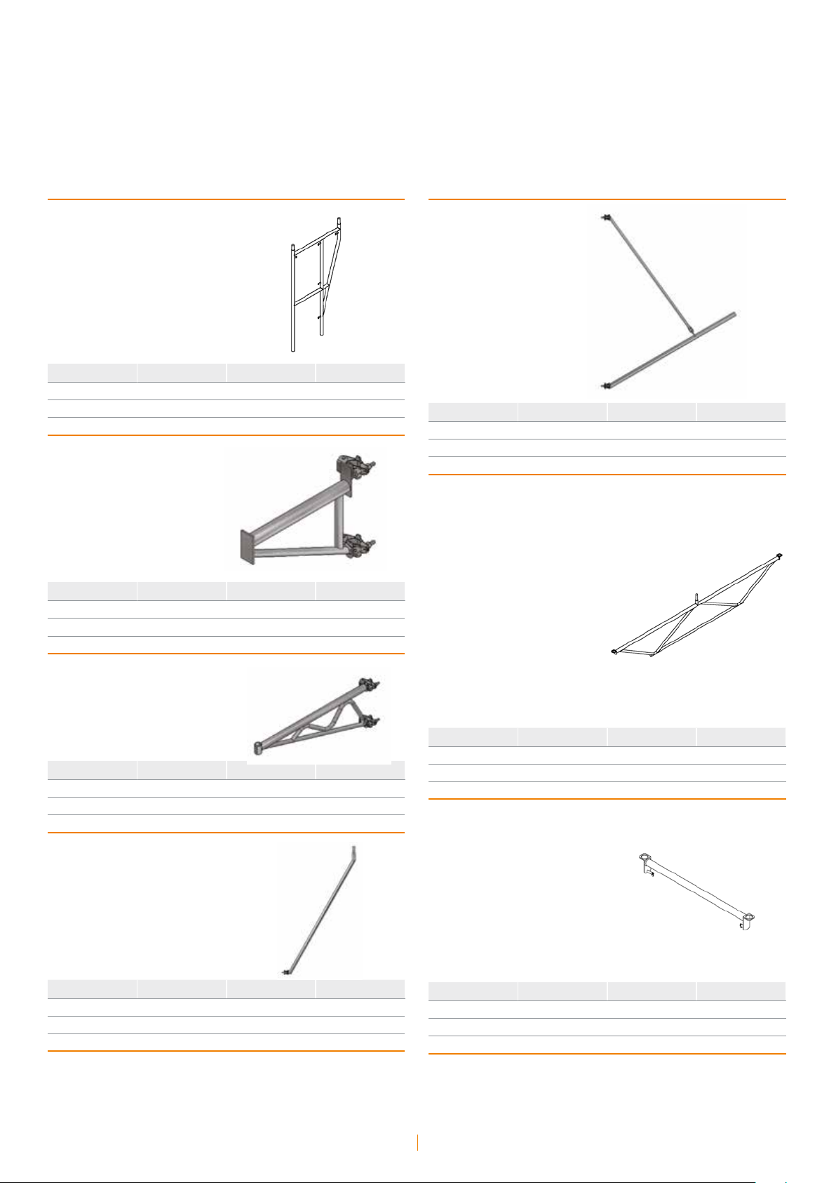
• horizontal truss beam
For example for diagram No. 1 in the ‘Truss beam in tube-coupler an
chorage’ section, there must be 2 modules on every node.
e result is the following:
Q
x 2S
o=Pw
w
A static layout of horizontal truss beam anchorages:
Q
R
0
0
Q
0
Q
0
Q
0
Q
0
Q
0
Q
R
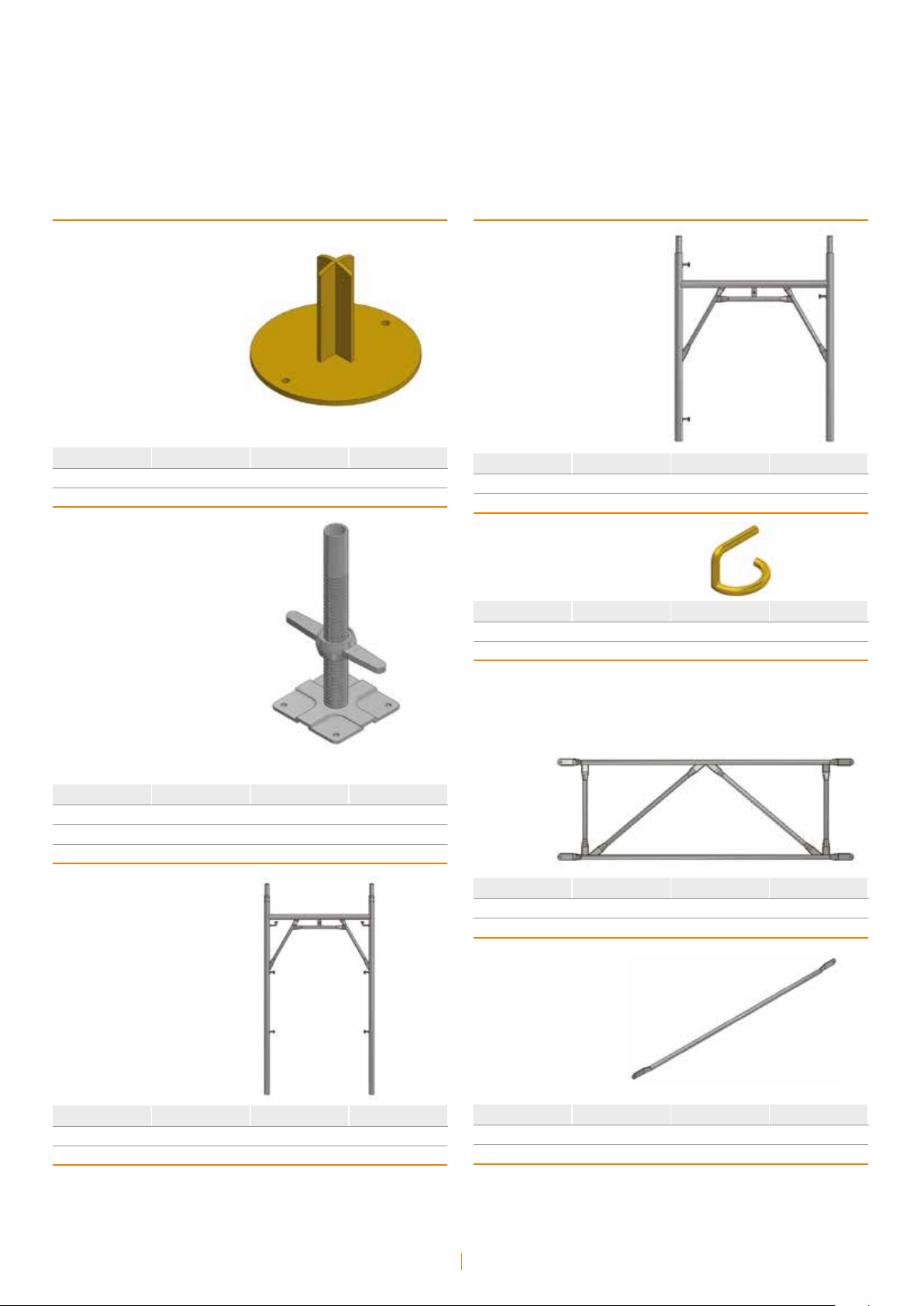
• vertical truss beam
For example, in design no. 2 in the “Truss beam in tube-coupler ancho
rage’ section, there must be 2 modules on every node. e result is the
following:
CHECKING THE TRUSS BEAMS
Having defined the acting loads and the static diagrams as explained in
the previous section, proceed with defining the truss beams using the
Ritter method or models utilizing finished elements or whatever other
methods are available for the purpose of obtaining the maximum stress
loads:
Tmax = maximum shear action
Mmax = maximum bending moment
• horizontal anchorage beam
Use tubes of ∅ 48.3 x 3.2 steel 235JRH for constructing the beams
described in the previous sections.
Both the transoms and the diagonals of the beans are added to the scaf
folding structure and immediately laid underneath the metallic decking
which forms the work bays.
Such beam elements will therefore only be subject to loads arising from
0
the results of the preceding sections.
erefore resistance and instability checks are carried out on the tran
soms and diagonals most subject to stress.
• vertical anchorage beams
e diagonals are made of tubes ∅ 48.3 x 3.2 in S235JRH steel coupled
0
to the transoms with swivel joints, while the beam transoms take advan
tage of the scaffolding uprights.
e resistance and instability checks of the scaffolding uprights must
therefore take into account both the vertical loads of traditional scaffol
ding on the uprights and the loads consequent to the bending moment
acting on the vertical truss beam.
-
-
-
-
Q
x 2S
v=Pw
w
Static diagram of the anchoring vertical truss beam
Q
Q
Q
Q
Q
v
v
v
v
v
R
R
ANCHORAGES OF THE EXTREMTIES
Every truss beam must be anchored to the part it is serving.
Refer to the anchorage types already described and see previous section
for the checks that have to be carried out.
v
WARNINGS
It is recommended to check the following:
• check the tightening torque of the joints
• check for the presence of metal ledger boards on bays which act as
horizontal load dividers
• depending on the type of anchorages placed on the end of the truss
beams, see the applicable warnings that apply to each under ‘Warnings’.
v
Instruction manual • Prefabricated frames
44

Anchorage with reinforced rod
for reinforced concrete
ERECTION PLAN
reinforcing rod sunk in
the casting
reinforced concrete wall
metal
decking
scaffolding
frame
CHECKING THE ANCHORAGE SUBJECT TO AN F1 LOAD
e checks to be carried out are the following:
• joint creep check:
F
< R
1
• tensile strength check of the anchorage tube
F
1
σ = _____ < σ1
A
• reinforcing rod check
e type of concrete and its characteristic Rbk resistance should be
considered;
in the absence of such information, assume Rbk= 250 daN/cm²
Based on the Rbk, the regulations in force provide the value of the resi
stance to adhesion of the reinforcing rod (τco).
e resistance to adherence of the rod in the concrete (RA):
∅ = reinforcing rod diameter
L’ = length of each of the 2 sections of reinforcing rods present within
the concrete casting
τco = concrete adherence resistance
-
CHARACTERISTICS OF THE MATERIALS USED
Materials having the geometrical and mechanical characteristics listed
below are to be used:
Tub e ∅ 48.3 x 3.2 in S235JRH steel
A = 4,59 cm²
J = 11,69 cm²
W = 4,85 cm³
i = 1,59 cm
σ 1 = 1600 daN/cm²
σ 2 = 1800 daN/cm²
Ton d e ∅ 8 FEB44K steel reinforcing rod for reinforced concrete
σ A = 2.600 daN/cm²
σ A = 0,5 daN/cm²
LOADS
e type of anchorage is only capable of supporting orthogonal loads
to the facade. For loads parallel to the façade, other types of anchorages
must be used as described above.
F1 load are determined in accordance with the regulations in force and
the calculation designs of the project.
RA = (∅ x π x L’ x 2) x τ
• adherence of the rod in the concrete check
F
< R
A
1
• strength check of the reinforcing rod
F
σ = _____ < σ
1
A
2 x AA
WARNINGS
e following is recommended:
• check the correct positioning of the rod in the concrete and the techni
cal/geometric properties (Φ ; AA)
• check the correct hold of the joints.
-
Instruction manual • Prefabricated frames
45

Anchorage
with structural steel plates
ERECTION PLAN
In the event of there being a particular geometry to the scaffolding
(suspended bearing) and/or particularly high loads, a steel plate joined
to the wall with mechanical anchors can be used.
metal
decking
scaffolding
plate detail
In general and in particular for the layout shown in ‘Anchorage with
structural steel plate’, the vertical load applied by the scaffolding uprights
must be added to the wind element.
CHECKING THE ANCHORAGE PLATE
With reference to the erection diagram and the ‘Anchorage with structural steel plate’ loads, carry out resistance checks on the plates acting as
loads:
• upper plate:
T = N
i
N = Ni x e
resistance check
M
σ = _____ < σ1
Wp
T
τ = _____ < π1
Ap
σ id = √ σ² + 3 π² < σ1
• lower plate
T = N
e
N = H M = Ne x e
CHARACTERISTICS OF THE MATERIALS USED
Materials having the geometrical and mechanical characteristics listed
below are to be used:
Tub e ∅ 48.3 x 3.2 in S235JRH steel
A = 4,59 cm²
J = 11,69 cm²
W = 4,85 cm³
i = 1,59 cm
σ 1 = 1600 daN/cm²
σ 2 = 1800 daN/cm²
Anchorage with structural steel plate; S235JR steel
Should ribbing be found, the geometric/mechanical properties to be
taken into consideration are:
AP = reagent area of the ribbing section
WP = resistant module of the ribbing section
σ 1 = 1600 daN/cm²
σ 2 = 1800 daN/cm²
LOADS
e acting load on the anchor plate is transmitted by the ledger or by the
upright that is directly attached to it.
verification of the anchors
N
M
σ = _____ + _____ < σ1
A
W
p
p
T
τ = _____ < π1
Ap
σ id = √ σ² + 3 π² < σ1
• verification of the anchors
e loads acting on the single anchors are:
T
Tb = _____ shear on the single anchor
2
M
Nb = _____ shear on the single anchor
d
e Tb and Nb values must be compared with the bearing capacities of
each anchor as supplied by the maker, reduced by the safety coefficient
2.2.
Instruction manual • Prefabricated frames
46
Erection sequence
Instruction manual • Prefabricated frames
47

Connection
elements
m
e
t
s
y
s
t
n
o
P
l
a
e
R
-
s
g
n
i
t
t
g
n
i
h
s
u
B
5
T
m
e
t
s
y
s
l
a
D
l
e
T
-
s
g
n
i
t
t
l
w
a
P
m
e
t
s
y
s
m
r
o
f
i
n
U
-
s
g
n
i
t
t
l
w
a
P
a
D
l
e
T
-
s
g
n
i
t
t
l
w
a
P
m
e
t
s
y
s
H
l
Instruction manual • Prefabricated frames
48

Erection sequence
1 • positioning the base
2 • positioning the frames
4 • inserting the ledger
5 • erection second frame with guardrail
3 • leveling the base
6 • erecting the second ledger
Instruction manual • Prefabricated frames
49

Erection sequence
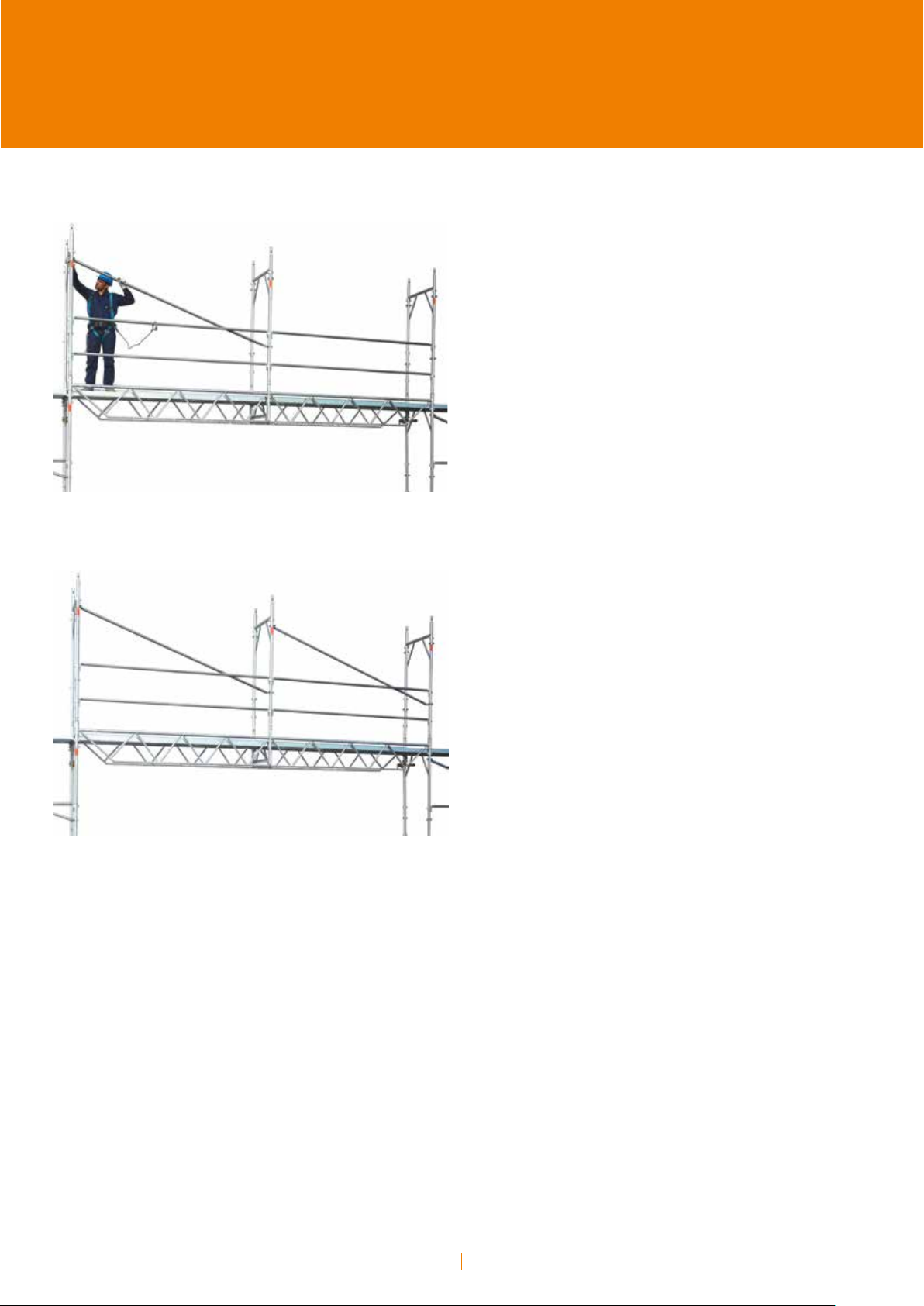
7 • erecting the vertical-diagonal brace
8 • checking the level
10 • checking the level
11 • erecting the next modules
9 • checking the distance from the facade
12 • erecting the next modules
Instruction manual • Prefabricated frames
50

Erection sequence
13 • erecting the next modules
14 • inserting the anchorage
16 • erecting metal ledger boards
17 • erecting metal ledger boards
15 • inserting the anchorage
18 • erecting plank with trapdoor
Instruction manual • Prefabricated frames
51

Erection sequence
19 • erecting plank with trapdoor
20 • ladder of the plank with trapdoor
22 • first level
23 • passage to the upper level
21 • inserting the ladder of the plank with trapdoor
24 • attaching the holding cable before mounting the bay
Instruction manual • Prefabricated frames
52

Erection sequence
25 • closing the trapdoor
26 • start of frame erection of level 1
28 • erecting level 1 frame
29 • erecting frame pins
27 • erecting level 1 frame
30 • erecting the level 1 ledger
Instruction manual • Prefabricated frames
53

Erection sequence
31 • erecting 1st level guardrail 32 • erecting the level 1 vertical-diagonal brace
t
n
o
P
l
a
e
R
-
e
r
u
t
c
u
r
t
s
l
i
a
r
d
r
a
u
g
l
a
c
i
p
y
t
m
r
o
f
i
n
U
-
e
r
u
t
c
u
r
t
s
l
i
a
r
d
r
a
u
g
l
a
c
i
p
y
t
u
r
t
s
l
i
a
r
d
r
a
u
g
l
a
c
i
p
y
t
u
r
t
s
l
i
a
r
d
r
a
u
g
l
a
c
i
p
y
t
e
T
-
e
r
u
t
c
e
T
-
e
r
u
t
c
5
T
l
a
D
l
H
l
a
D
l
Instruction manual • Prefabricated frames
54

Erection sequence
33 • erecting the next level 1 modules
34 • erecting the level 1 rear ledger
36 • level 1 toeboard detail
37 • level 1 toeboard detail
35 • erecting the level 1 toeboard
38 • erecting the level 1 toeboard
Instruction manual • Prefabricated frames
55

Erection sequence
39 • erecting 1st level side fencing
40 • erecting 1st level side fencing
42 • erecting the level 2 planks
43 • erecting the level 2 planks
41 • erecting an anchorage on level where needed
44 • erecting the level 2 planks with trapdoor
Instruction manual • Prefabricated frames
56

Erection sequence
45 • erecting the level 2 planks with trapdoor
46 • erecting planks on all level 2 modules
48 • erecting top upright joint on level 2
49 • passage to the level 2
47 • erecting top upright on level 2
50 • erecting transoms and guardrails on level 2
Instruction manual • Prefabricated frames
57

Erection sequence
51 • erecting 2nd level side fencing
52 • erecting street protection guard
54 • street protection guard detail
55 • erecting street protection guard planks
53 • street protection guard detail
56 • erecting street protection guard planks
Instruction manual • Prefabricated frames
58

Erection sequence
57 • street protection guard planks detail
58 • erecting bracket brace
60 • erection of the plank with bracket brace
61 • erecting the planks on the brackets
59 • erecting plank bracket brace
62 • erecting the planks on the brackets
Instruction manual • Prefabricated frames
59

Erection sequence
63 • erecting the connections of the pedestrian walk-through frame
64 • erecting the planks on the pedestrian walk-through frame
66 • erecting carriage beam connecting beams
67 • erecting decking on the carriage beam
65 • erecting carriage beams
68 • erecting frames and transoms above the carriage beams
Instruction manual • Prefabricated frames
60
Erection sequence
69 • erecting the vertical-diagonal brace above the carriage beams
70 • end of erection above the carriage beams
Instruction manual • Prefabricated frames
61

Instruction manual • Prefabricated frames
62

Certifications
Instruction manual • Prefabricated frames
63

Tube-coupler system
CNAS - MCC
Test report
no. 2009-52558
ICECON
Certificat
de conformitate
nr. 0835/2017
IGQ
Certificati di prodotto
P021A
Ponteggio metallico fisso
a tubi e giunti
Steel tube scaffold
couplers
China
Technischen
Universität München
Prüfbescheinigung
gemäß DIN EN 74
Rohr-KupplungsSystem 9466
Schele de fațadă,
din oțel T/C
Romania
Italy
Prefabricated frames:
Realpont 75 system
Germany
CNAS - MCC
Test reports no. TC-JG1Q-2009-09 ; 15; 16; 17; 18.
Frame Realpont 75
Horizontal diagonals
Bracket, Bridging ledger
China
Instruction manual • Prefabricated frames
64

ICECON
Certificat de conformitate
nr. 0834/2017
IGQ
Certificato
di prodotto P021I
Schele de fațadă,
din oțel RP 75
Romania
Prefabricated frames:
Realpont 105/EU92 system
Realpont 75 a telai
prefabbricati
Italy
CNAS - MCC
Test reports no. TC-JG1Q-2009-08; 15; 16; 17; 18.
Frame Realpont 105
Horizontal diagonals
Bracket, Bridging ledger
ICECON
Certificat de conformitate
nr. 0834/2017
Schele de fațadă,
din oțel RP 105
China
IGQ
Certificati di prodotto
P021H, P021L
Realpont 105/EU92
a telai prefabbricati
Germany
Romania
Instruction manual • Prefabricated frames
65

Prefabricated frames:
Tel Dal T5/Uniform system
ICECON
Certificat de conformitate
nr. 459/2007
IGQ
Certificati di prodotto P021D
ICECON
Certificat de conformitate
nr. 0836.1/2017
Schele de fațadă,
din oțel Uniform
Schele de fațadă,
din oțel T5
Romania
IGQ
Certificati
di prodotto P021F
Uniform a telai
prefabbricati
Tel Dal 3, Tel Dal 5 bis,
Tel Dal 5 ter
Italy
Romania
Prefabricated frames:
Tel Dal H system
Italy
IGQ
Certificati di prodotto
P021E
Tel Dal H a telai
prefabbricati
Italy
Instruction manual • Prefabricated frames
66

Prefabricated frames
IGQ
Certificati di prodotto
P021B
IGQ
Certificati di prodotto
P021C
HTP a telai
prefabbricati
Italy
IGQ
Certificati di prodotto
P021M
RP 390 a telai
prefabbricati
PRATICUS a telai
prefabbricati
Italy
IGQ
Certificati di prodotto
P021N
RP 490 a telai
prefabbricati
Italy
IGQ
Certificati di prodotto
P021O
T5-SX a telai
prefabbricati
Italy
Italy
Instruction manual • Prefabricated frames
67

Deck planks
CNAS - MCC
Test report
no. TC-JG1-Q-2009-10
CNAS - MCC
Test report
no. TC-JG1-Q-2009-11
Metal plank mm 330x1800
China
CNAS - MCC
Test report
no. TC-JG1-Q-2009-12
Metal plank mm 490x1800
Metal plank mm 330x2500
China
CNAS - MCC
Test report
no. TC-JG1-Q-2009-13
Metal plank mm 490x2500
China
China
Instruction manual • Prefabricated frames
68


• September 2019 - EN
Construction equipment division
Divisione cantieristica edile
via Giovanni della Casa, 12
20151 Milano - Italy
Tel. +39 . 02 30 704 1
Fax +39 . 02 33 402 706
cantieristica@marcegaglia.com
www.marcegagliabuildtech.com
 Loading...