

CAFER RACER 69mm
Cortesia de www.marcadoresdemoto.com
Cortesia de www.marcadoresdemoto.com
Thank you for purchasing speedometer, before operating the unit, please read the instruction thoroughly and retain it for the future reference.
INsTRUCTION
Notice
1. applications only.
DC 12V
2.For installation, please follow the steps described in manual. Any damage caused by wrong installation shall be imputed to the users.
3.To avoid the short circuit, please don't pull the wire when installing. Don't break or modify the wire terminal.
4.Do not disassemble or change any parts excluding the manual description.
5.The interior examination or maintenance should be executed by our professionals.
MARK MEANING:
NOTE
You could get the installation details from the information behind the mark.
Some processes must be followed to avoid the affection caused by wrong installation.
WARNING!
CAUTION!
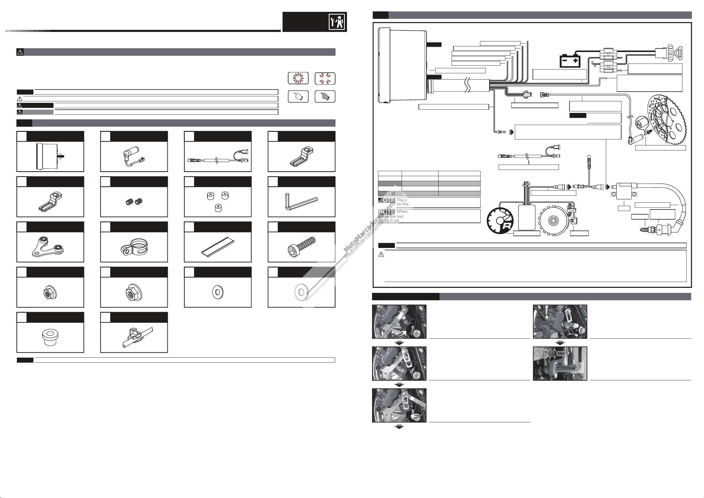
Accessory
1-1
LCD meter X 1
1 2 3
Some processes must be followed to avoid damages to yourself or the public.
Some processes must be followed to avoid the damage to the vehicle.
Passive speed sensor X 1
RPM X 1 wire set
4
LIGHT ON FLASH
PRESS THE
BUTTON ONE
TIME
M8/ S type speed
sensor X 1bracket
PRESS THE
BUTTON 3
SECONDS
Wiring installation instructions
2-1
LCD meter (A ccessory 1
Dark brown RPM Signal wire─
Purple Neutral
Orange Left- turn signal(+ 12V)─
Blue Right turn signal(+12V )─
Yellow High beam─ (+12V)
Gray Warning la mp(- )─
─ (-)
)
Red / Postive pole (Connect
to the battery DC 12V)
Speed sensor wiring
Please choose either Type A or Type B RPM wire
according to the need and then follow the
instruction below to install at the proper position.
Digital speed signal
sensor (Accessory 2)
Speed Sensor is
NOTE
a "Hall Sensor ".
Brown / "+"Wire connect key
on main power switchDC 12V
Black / Ground wire connect
to the vehicle body or the
engine (It must be a good
ground)
Magnet (Accessory 8)
M10/ S type speed
5 6
sensor X 1bracket
Meter bracket X 1
9 10
M5 X P0.8 nut X 3 M6 washer X 1
13
Aluminum bush X 1
17
Hexagon socket
screw X 2
Handle bar clamp X 1
M6 X P1.0 nut X 1 M5 washer X 3
14
Connect terminal X 8
18
D6 X 5L mm magnet X 6
7
Rubber X 1
11
15 16
2.5 mm spanner X 1
8
M6 X 10L screw X 1
12
Main switc h wiring reference:
"+" Color "-" Color
YAMAHA
HONDA
SUZUKI
SYM
NOTE
NOTE
follow the instruction. If you connect the red & brown
wiring in parallel will cause the meter work improperly.
NOTE
Brown
Brown
Black
Black Green
The color li sted above may di
on the model .
When connecting the power wiring, please
When connecting the power wiring, please follow the instruction. If you connect the red & brown wiring in parallel will cause the meter work improperly.
Black
Black
Green
ffer de pending
RPM wire set
Tachometer
(Accessory 3)
Ignition coil positive
Flywh eel
EMS
CDI
Ignit ion
pulse
pick up
Coil
Spark plug wire
Spark plug
cap
Spark
The RPM w ire i nst allatio n
Please check the polarity of your ignition coil, before you connect the RPM sensor type B there. An incorrect installation can lead to a defect of the meter or destroy
the electrical system of your vehicle.
Transistor Ignition: If your vehicle has a transistor ignition system, connect the tach to the negative pole of the ignition coil.
ignition: If your vehicle has a CDI ignition system, connect the speed sensor to the positive pole of the ignition coil.
CDI
MOTO / SCOOTER
S type speed sensor bracket instruction
Loose the screw on the caliper
Install the speed sensor.
NOTE
Please contact if the items you open are not the same, with the above-listed one.the local distributor
Install the S type bracket on the caliper.
Please adjust the bracket to the proper angle
and then screw it up. Please make sure the
disc screw could pass the hole on
for you to install the sensor into the same hole
for catching the speed signal.
the bracket
Adjusting the distance between the sensor
and screw to get the best speed signal.
Please make sure the distance is under
to get the best signal.
2 mm
wh 035 ba0 02
P.S.
Cortesia de www.marcadoresdemoto.com
Cortesia de www.marcadoresdemoto.com
The active speed sensor could be installed by the metal parts to detect the speed.
EX. 1 The disc screw.
EX. 2 The disc to detect the disc gap. (Please make sure the distances between the gaps are the same in advance to avoid wrong
speed signal.)
EX. 3 The sprocket to detect the disc gap. (Please make sure the distances between the gaps are the same in advance to avoid wrong
speed signal.)
We will suggest you to catch the speed
maximum sensor points the speed sensor could detect is 20 points per turn.
After installation, please use your hand to turn the tire to see is everything ok. The LED on the active speed sensor will light up once
the signal is detected.
EX. 1
The hexagon socket disc screw
speed
senso r
speed
senso r
the detec t range
speed
senso r
the detec t range
speed
senso r
speed
senso r
The best detect area: The edge of the hexagon socket screw.
The hexagon screw
The best detect area: The middle of the screws.
EX. 2
speed sen sor spee d sensor
the detec t range
The disc
The best detect area: Please detect the speed signal from the gaps of the disc.
EX. 3
speed sen sor spee d sensor
The sprocket
The best detect area: Please detect the speed signal from the gaps of the sprocket.
from the disc screws. The more the sensor points are, the better the speed accuracy is. The
Please don't catch the signal from the middle hole of the hexagon socket screw to avoid wrong signal.
Some hexagon screw center is with a small hole in the center in this case, we will suggest you to catch
the signal from the edge of the screw like the hexagon socket screw.
Please note that there are discs with the gaps in different difference, and this method will not work on it!
Please note that there are sprockets with the gaps in different difference, and this method will not work
on it!
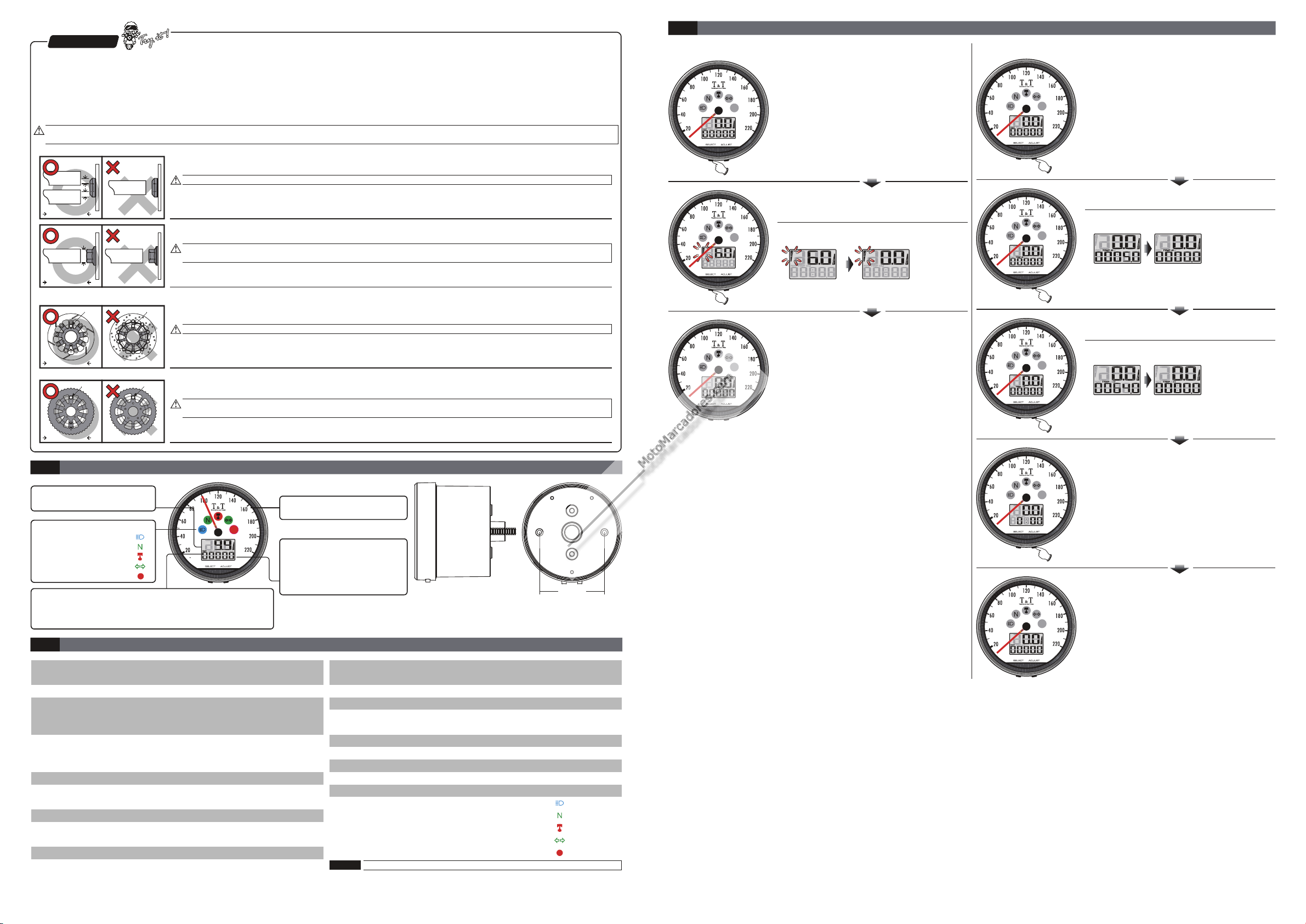
Function switch instruction
3-3
●Select button function instruction
●
In RPM screen, Press the Select button once
to switch function from ODO to
record
● Max. RPM record
In screen, Press the Select
button once to switch from the
record
●
Hold pressing the Adjust button for 3 seconds
to reset the
●The RPM screen.
.
Max. RPM
Max. RPM
function to the main screen.
Max. RPM record.
●Ad
just button function instruction
● A
djust In ODO screen, press the button once to
switch the function from ODO meter to trip A.
● Adjust In trip A screen, press the button once to
switch from trip A to trip B
ld pressing the Adjust button for 3 seconds
●Ho
to reset the trip A.
● Adjust In trip B screen, press the button once
to switch from trip B to clock screen.
●Hold pressing the Adjust button for 3 seconds
to reset the trip A.
the detec t range
Basic function instruction
3-1
Tachometer
Display range:20,000 RPM●
Telltales
●High beam (Blue)
●Neutral (Green)
●RPM Shift light RED( )
●Repeater Green( )
●Reserve RED( )
Clock
24 H●
3-2
●Speedometer
Trip meter
Display range: 0~9999.
●
automatically after 0~9999.9 km (mile).
Display unit: 0.1 km (mile).
●
Function, setting instruction
Display range: 0~220
Display unit: km/h & MPH or alternative
○Display internal
○Odometer
<0.5 second
Display range: 0~99999 km (mile), reset
automatically after 99999 km (mile)
isplay unit: 1 km (mile)
D
○Trip meter A . B
Display range: 0~9999.9 km (mile), reset
automatically after 0~9999.9 km (mile).
Display unit: 0.1 km (mile).
○Top speed rec
ord
○Tire circumference
Display range: 0~220
Setting range 300~2,500 mm:
Sensor point: 1~20 Setting unit 1 ‧ :
●Tachometer
○The shift light
Display range:20,000 RPM
Setting range:5000~20000 RPM
Setting unit:100 RPM
○Warning
○RPM input pulse
F-OFF (LIGHT ON) FLASH‧F-ON ( )
Display range:0.5 1~6,
9 km (mile), reset
km/h
km/h
Speedometer
Display range: 0~220 km/h ●
Odometer
Display range: 0~99,999
●
km (mile), reset automatically
after 99,999 km (mile)
Display unit: 1 km (mile)
●
○The RPM input pulse
○Max. RPM record
●Clock
●Backlight brightness
●Effective voltage
●Effective temperature range
●Meter standard
●Meter size
Meter weight●
Telltales●
Design and specification are subject to change without notice!
NOTE
45 mm
Setting range:Hi-ACT (Positive wave pulse)
Lo-ACT (Negative wave pulse)
Display range: 0~20,000 RPM
24 H
Setting range:1-5 (Darkest)~5-5 (Brightest)
Setting unit:Each level represent
s 20%
DC 12v
-10~+60 °C
JIS D 0203 S2
85.5 X 54.5 mm
Around 330 g
High beam (Blue)
Neutral (Green)
RPM Shift light (RED)
Repeater (Green)
Reserve (RED)
● Adjust In clock screen, press the button once
to switch from clock to ODO screen.
●The ODO screen.
wh 035 ba0 02

Function setting instruction
Cortesia de www.marcadoresdemoto.com
Cortesia de www.marcadoresdemoto.com
4
●In main screen, hold pressing the Select +
Adjust button for 3 seconds to enter the
setting screen.
Speed unit setting
4-1
●Press the button one time to enter the
speed unit setting
●●EX.To cha nge t he se tt ing f rom k m/h t o
MP H.
Pres s the Adjus t but ton t o cha nge t he
setting .
註
NOTE
Now the d i s fla shi ngef au lt
NOTE
NOTE
●●Pres s the Sele ct bu tto n onc e to go b ack t o
the Sp eed unit sett ing s cre en.
EX. Th e Spe ed un it se tting is cha nge d
from k m /h t o MPH.
●Pres s the Adjus t but ton o nce t o go ba ck to
th e tire circu mfe ren ce an d sen sor p oint
se tting s cre en.
4-2
●Press the Select button one time to enter the
tire circumference setting
Select
Defa ult :km /h
Setting range: km/h or .MPH
The odometer & trip meter will change
together with the speed unit.
The tire circumference and sensor point setting.
●
●Press the Select button to move to the digit
註
NOTE
NOTE
●
●
the set ting, p lease make sure the setting n umber i s
corre ct befo re you make the se ttin g.
You could define the valve
as the starting point and the
terminal point to measure
the wheel circumference
with a measuring tape.
●Pr ess t he Adj ust b utt on to choose the
●
●
●
●Press the Select button to move to the
註
NOTE
●Pr ess t he Adj ust b utt on to choose the
EX. The tire circumference is 1,300 mm.
you want to set.
Defa ult :1, 000 m m
Now the d i s fla shi ngef au lt
The tire cir cumference se tting range:
300~1,00 0 mm, and the digit y ou set is
from left to right in order.
CAUTION!
Pleas e measu re the ti re circ umference ( the tir e you wil l
insta ll the se nsor on) and make sure th e number of
magne t senso r point ( You could in stall t he magn et into
the dis c screw o r the spr ocket screw.)
The spe ed disp layed on the met er will be affec ted by
cm
130
sett ing n umb er.
Press the Select button once to go back to
the sensor point setting screen.
EX. The tire circumference setting is
changed from 1,000 mm to 1,300 mm.
EX. The sensor point you want to set is 6.
digit you want to set.
Defa ult :01 P
Now the d i s fla shi ngef au lt
The sensor point setting range:
1~20 points. You could change the
setting from left to right.
sett ing n umb er.
●Pr ess t he Se lec t butto n onc e to go back t o
th e tire circu mfe ren ce an d sen sor p oint
se tting s cre en.
●Pres s the Adjus t but ton o nce t o go ba ck to
th e RPM p ulse and i nput signa l set tin g
se tting s cre en.
RPM pulse and settinginput signal
4-3
●Pres s the but ton o ne ti me to e nte r
th e RPM p ulse setti ng.
●
Enter the number of ignition signals per
crankshaft revolution ( P value).
This may vary according to the vehicle
manufacturer/model and type of engine:
●
If a 4-stroke engine fires at every second
crankshaft revolution, enter P=0.5 (on 1-,
2- and 3-cylinder 4-stroke engines with one
ignition coil for each cylinder)
●
If a 4-stroke engine fires once per crankshaft
revol
4-stroke engines with one ignition coil for two
cylinders)
●
2-stroke engines fire once per crankshaft
revolution; enter P=1
●
In the case of vehicles which have a
distributor (mostly cars), you can enter P
values up to 4, according to the number of
cylinders.
●
If you do not know how often your engine
fires per crankshaft revolution, s
assuming the standard setting (P=1) the
instrument cannot be damaged if you do
this. If an incorrect engine
rpm is displayed, you should vary the P value
by entering it manually until the figure
displayed is realistic.
●
Example illustration: The setting is changed
from P=1 to P=2.
●
Press the selection button and change to the
function for setting the shift war
Sele ct
“ ”
ution, enter P=1 (on 2-, 4- and 6-cylinder
tart by
–
ning
●
EX. We w oul d lik e to ch ang e the s ettin g
to L oAc t. (The nega tiv e imp uls e)
●
Pres s the Adjus t but ton t o cho ose t he in put
si gn al yo u wan t to se t.
註
NOTE
註
NOTE
註
NOTE
●●Press the Select button once to go back to
●Pres s the Adjus t but ton o nce t o go ba ck to
●Pres s the Sele ct bu tto n one t ime t o ent er
●●EX: You want the shift light to light on at
註
NOTE
註
NOTE
●Pres s the Adjus t but ton t o cho ose t he
Defa ult :Hi Act
Now the d i s fla shi ngef au lt
The impulse setting range is
between Hi (the positive impulse)&
Lo (the negative impulse)
If the tachometer can't detect the
signal (No RPM is displayed on the
screen), you could choose another
setting, and check it again.
the RPM pulse and input signal setting
screen.
EX. The input signal setting is changed
from HiAct to LoAct.
th e shift ligh t and s hif t lig ht wa rning sett ing
se tting s cre en.
Shiftlight setting
4-4
th e Shift ligh t set tin g.
8000 RPM Please change the shift light
setting value to 8500 directly.
Press the Select button to move to the digit
you want to set.
Defa ult :8, 000 RPM
Now the d i s fla shi ngef au lt
Setting
range 5,000~20,000 RPM
Setting
sett ing n umb er.
:
unit 100 RPM
:

●Pres s the Sele ct bu tto n to ch oos e the
Cortesia de www.marcadoresdemoto.com
Cortesia de www.marcadoresdemoto.com
Shif t lig ht
EX: Now t he sh if t lig ht se tti ng is c han ged
●
from 8, 000RPM to 8,500 R PM.
●
EX. You wan t to se t the shif t lig ht F- ON
(F lash) .
●Pres s the Adjus t but ton t o cho ose t he
se tting n umb er.
NOTE
Now the d i s fla shi ngef au lt
NOTE
sett ing .
Defa ult : Lig ht onF -OFF ( )
Setting range: F-OFF(Light on)
F-ON(Flash).
、
●
EX. Now the setting is changed from 0:00
to 10:00.
●
Press the Select button to enter the minute
setting.
●●EX. To change the setting to 14:10.
Press the Select button to move to the digit
you want to set.
Defa ult :0 minutes.
NOTE
Now the d i s fla shi ngef au lt
Setting range: 00~59 minutes.
NOTE
●
EX. You want to set the backlight at
(60%).
●
Press the Adjust button to choose the setting
number.
Defa ult :5- 5
NOTE
Now the d i s fla shi ngef au lt
Setting range:1-5(Darkest)~5-5
NOTE
(Brightest),5 different levels available.
Setting unit:20% per level.
The backlight brightness will change
immediately after you set the value.
●●Press the Select button one time to enter
the backlight setting.
EX: ackli
from to .
5-5 (100%) 3-5 (60%)
ght setting The b setting is changed
3-5
●Press the Select button once to enter the
external odometer setting screen.
●
EX. Set the odomete r to 50 00 km .
●Pr ess t he Se lec t butto n to move to the di git
yo u wan t to set.
Defa ult : mile00 ,00 0km( )
NOTE
Now the d i s fla shi ng
NOTE
ef au lt
Display range:0~99,999 km (mile)
●●Press the Select button once to go back to
the RPM input signal and shiftlight setting
screen.
EX. The shiftlight setting is changed
from F-OFF(Light on) to F-ON(Flash).
ress the Adj ust b utt on to c hoo se th e
●P
cl ock s ettin g scr een .
Clock setting
4-5
●Press the Select button one time to enter
the clock setting.
●Pr ess t he Adj ust b utt on to choose the
setting n umb er.
●
Press the Select button once to go back to
the clock setting screen.
● EX. Now the setting is changed from 10:
to 10:10.
●Pr ess t he Adj ust b utt on to choose the
ba cklig ht se tti ng sc ree n.
00
●P
ress the Adj ust b utt on to
od ometer dis pla y scr een .
Me ter Odo meter display
4-7
●Press the button to enter the odometer
display screen.
●
EX. The internal odometer display is 12500
km.
●Press the Select button once to enter the
external odometer setting screen.
This disp aly o nly f or vi ewi ng cu rrent
mile age o n the mete r.
Select
choo se th e
●Pr ess t he Adj ust b utt on to ch
setting n umb er.
●
Pres s the Sele ct bu tto n onc e to go
ba ck to t he Meter Odomet er sc ree n.
●
EX. Th e odo met er se tting has be en
ch anged from 0 km t o .
Pres s the Adjus t but ton X 3 to go
●
ba ck to t he main screen.
●The main screen.
oose the
5, 00 0 km
secon ds
●●EX. To change the setting to 10:00.
number.
NOTE
NOTE
註
Press the Adjust button to choose the setting
Defa ult :0 H.
Now the d i s fla shi ngef au lt
Setting range: 0~23 H.
Backlight setting
4-6
●Press the Select button one time to enter the
backlight setting.
●Pr ess t he Adj ust b utt on to choose the
external odometer setting screen.
External Odo meter s etting
4-8

Trouble shooting
Cortesia de www.marcadoresdemoto.com
Cortesia de www.marcadoresdemoto.com
5
The following situation do not indicate malfunction of the meter. Please check the following before taking it in for repair.
Trouble TroubleCheck item Check item
The meter doesn't work
when the power is on.
Speed does not appear
or appear incorrectly.
Tachometer does not
appear or appear
incorrectly.
※If still can't solve the problems according to the steps above, please contact with distributors or us.
●
The power doesn't supply to the meter.
→
Please make sure the wiring is connected.
The wiring and fuse are not broken.
→
The battery is broken or the battery is too
old to supply enough power
make the meter work.
●
Please make sure the speed sensor is
connected correctly.
●
Please check the tire-size setting.
→
please refer to the m
Please check the RPM sensor wiring is
●
connected correctly.
●
Please check the spark plug is R type or
not. If not, please replace the spark plug
with the R type spark plug.
●
Please check your setting.
→
Please refer to the manual a3.
DC 12V to
anual a2.
The clock is incorrect.
Backlight doesn't work or
doesn't have enough
brightness
Telltale doesn't work
●Do
you connect the wiring correctly.
→
Please chec
connects to the battery, and main
switch positive wiring (Brown) connects
to the main switch.
Please check your setting.
●
Please refer to the manual a5.
→
The harness connection might be wrong
●
Please check the backlight wire is properly
→
connected according to t
Please check your setting.
●
Please refer to the manual a6.
→
●
The harness conne
Please check the harness wire is properly
→
connected according to the instruction.
k the positive wire (Red)
he instruction.
ction might be wrong
 Loading...