

Marbletrend Milano, Milano Flush to Wall Suite Installation Manual
INSTALLATION INSTRUCTIONS
MILANO FLUSH TO WALL SUITE Code J1426
DESCRIPTION
This toilet suite is a fully concealed, back to wall suite that has a variable set out option.
The suite is supplied with an adjustable S Trap connector fitting that permits a 90-180mm set out range. The suite can
also be connected in a P Trap configuration (fittings not supplied).
The water inlet is adjustable.
The cistern is bolted to the pan from inside the cistern tank and can be removed if necessary for servicing.
The suite has a soft close seat that is attached via top-fixed bolts. The seat is removable for cleaning.
Floor fixing brackets are provided.
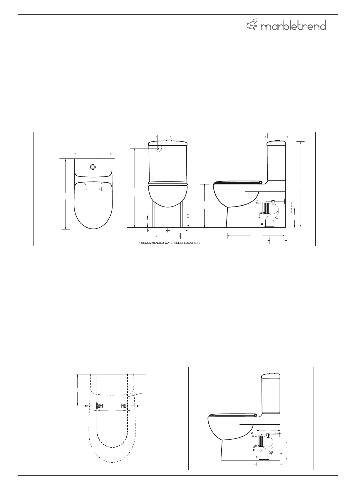
GENERAL DIMENSIONS
80*
160
340
145
680
745*
400
360
150*
220*
250
220*
150*
575
90-180
90-180
INSTALLATION STEPS
1. Inspect pan, cistern and seat for any transit damage before starting installation.
2. Check site roughing in, cistern tap position and assembly dimensions before starting installation. The WC must be
installed on a level surface.
3. Insert the threaded insert and hex nut to pan platform as in DIAGRAM 4
4. Place the pan in position ensuring it is aligned with the centerline of the sewer connection. Mark the location of the
pan fixing bolt holes.
5. Remove pan and locate the position of the floor brackets. Drill the
DIAGRAM 1
holes (10mm) to attach the floor fixing brackets.
6. For S Trap installation cut the threaded bracing prop on the pan connector elbow to the correct length to suit the set
out. Cut the pan connector fitting to the correct length( mm from wall) and height(180mm from floor) to suit the 250
job. Install the connector and screw the bracing prop to the back wall. Check the outlet connection fit with the pan
fully back against the wall.(DIAGRAM 2)
7. For P Trap installation a pan connector and extension will be required.
180
180
800
800
DIAGRAM 1
290
Drill 10mm
fixing holes
OUTLINE OF
FOOT OF PAN
Pan fixing bolt
1/3
DIAGRAM 2
250
290
BRACING
PROP
180
100
I0091MT
INSTALLATION INSTRUCTIONS
MILANO FLUSH TO WALL SUITE Code J1426
8. The water supply to the inlet valve must be connected in accordance with AS/NZ3500.1. Fit the
blanking plug provided to seal the inlet hole in the base of the cistern and connect the flexihose to the
water inlet.
Note: for bottom water entry option a bottom water entry valve is required(not supplied). Refer to DIAGRAM 3.
9. Place the WC into position ensuring that it seals firmly to the pan connector
10. Insert the floor bracket fixing screws through the fixing holes in the base of the pan and tighten. Attach the
decorative caps.
11. For mortar bedding use a 4:1 sand and standard cement mix (do not use Rapid Hardening cement). If the
floor is tiled, cut out the tiles beneath the pan to create a good bonding surface.
12. Place the rubber foam sealing-ring in position and place the cistern in position on the WC pan. Check that
the rubber seal is seated correctly.
13. Secure the cistern to the pan by screwing the cistern fixing bolts and washers to the threaded insert in the
top of the cistern platform (the body of the outlet valve may be temporarily removed from the base to make
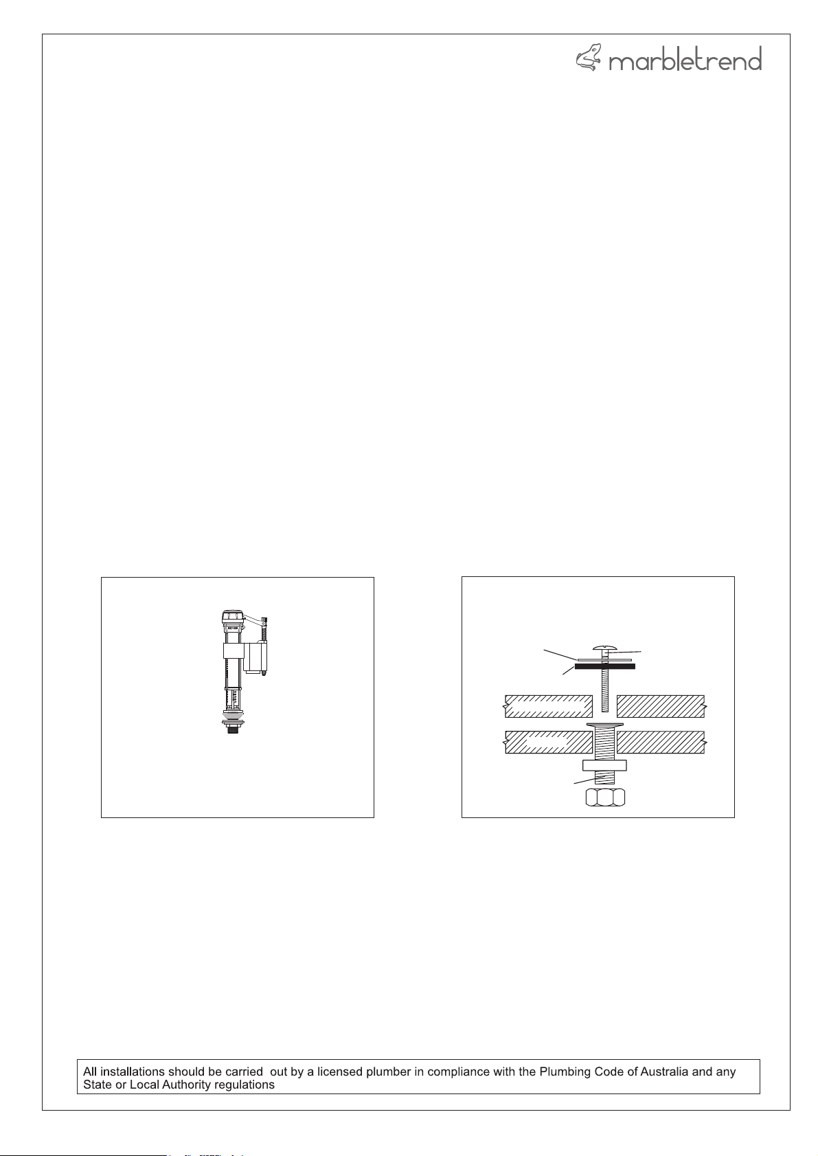
this easier). Screw down firmly to compress the foam seal ring. Refer to DIAGRAM 4
14. For back water entry - attach the inlet valve water supply hose to the water supply.
15. Always flush the water supply pipes before connecting the cistern inlet valve to the cistern tap.
16. Fill the cistern and check the water level, if necessary adjust the inlet valve float.
17. Attach the cistern lid and buttons and test flush several times while checking for leaks.
18. Waterproof sealant finishing may be used around the base of the WC.
19. Fit seat
DIAGRAM 4
OPTIONAL INLET VALVE (XI210) REQUIRED
FOR BOTTOM WATER ENTRY INSTALLATIONS
FLUSH WATER VOLUME TO BE ADJUSTED TO
THE LEVEL MARK ON THE CISTERN
DIAGRAM 4
SS WASHER
RUBBER WASHER
CISTERN BASE
PLASTIC WASHER
THREADED INSERT
CISTERN FIXING BOLTS
WC PAN
ASSEMBLY
BOLT
HEX NUT
2/3
I0091MT
 Loading...