

Marathon Special Products TERMINAL BLOCK Catalog Supplement
TERMINAL BLOCK TYPES
TERMINAL BLOCKS
TERMINAL
BLOCK TYPE
Studded
Feed-Thru
Single Stud
Connection
Motor
Blocks
Grounding
Lugs &
Connectors
Deadfront 28
PAGE # DESCRIPTION IMAGE
Barrier 30
Feed-thru terminal blocks are commonly used in telecom panel power
23
distribution units (PDU’s) and other applications where external power
needs to be transferred to feed a circuit.
Single stud terminals simply provide a single junction point to connect
25
two or more ring type terminals.
Motor terminal blocks are specically intended to be used with electric
26
motor junction boxes to provide delta or wye wiring congurations.
These wiring components are intended to be used for grounding in
27
electrical systems.
These rugged terminal blocks provide protection from direct contact
with live terminals.
These robust style of terminal strips are commonly used in utility
panels to aide in the control of power generation and transmission
equipment.
Double Row 31
Single Row 33
Military /
Navy
DIN
Sectionals
®
NEMA
Sectionals
Barrier terminal strips are the most cost effective means of junctioning
wires in lower power applications. Various hardware accessories are
available to meet circuit requirements.
These terminals are intended for junctioning wires at a single point by
means of a bare wire, prepared wire or hardware (quick-connects).
These terminal blocks are constructed to meet the requirements of Mili-
35
tary Specications A-A-59125 & MIL-T-55164-C, and are only to be used
in applications requiring compliance with these specications.
DIN sectionals provide a compact semi-touch proof construction for a
37
range of wire sizes. These provide end-users the ability to construct
terminals to various line lengths per application.
NEMA sectionals have an open barrier appearance and style in a
39
sectional construction to provide end-users the ability to construct
terminals to various line lengths per application.
Website Resources:
Dimensional drawings & 3D CAD files
Termination and mounting specifications
Detailed product/series datasheets
Check distributor stock
Request samples
NEMA is a trademark of National Electrical Manufacturers Association. All Rights Reserved.
22
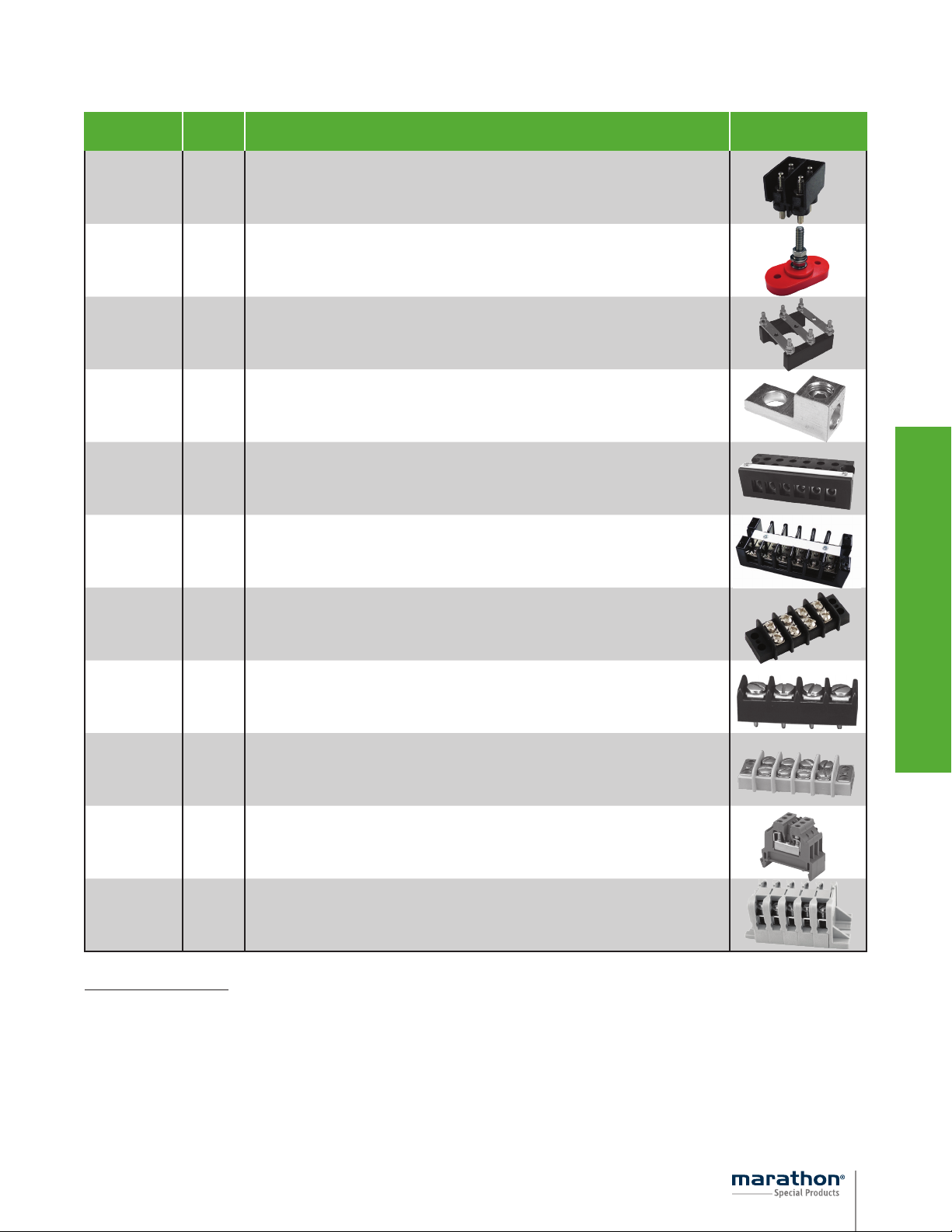
STUDDED FEED-THRU
TERMINAL BLOCKS
ELECTRICAL:
115 to 175 amps
300 volts AC/DC (UL)
Wire range is determined by the compression lugs used
Short circuit current rating (SCCR) of 10K
Factory and field wiring
STANDARDS:
UL 1059 recognized file no. XCFR2.E62806
CSA certified file no. LR19766 (CSA C22-2 No. 158)
CE (Component IEC 60947-7-1)
RoHS compliant (All)
WEBSITE RESOURCES:
Detailed product data sheets
• Material information
• Termination & mounting specifications
• Multiple wire rating specifications
• Detailed SCCR information
Dimensional drawings & 3D CAD files
Accessories available
ST722E2502
ORDERING CODE:
SERIES
B = Back Mount
E = End Mount
ST722
COVERS AVAILABLE:
Covers fit all styles available
CATALOG
NUMBER
C72201 1 Thermoplastic UL 94 V-0
C72202 2 Thermoplastic UL 94 V-0
C72203 3 Thermoplastic UL 94 V-0
C72204 4 Thermoplastic UL 94 V-0
C72205 5 Thermoplastic UL 94 V-0
C72206 6 Thermoplastic UL 94 V-0
MOUNTING
STYLE
(x)
POLES
(x)
THREAD SIZE
(xx)
25 = 1/4-20
19 = #10-32
M6 = M6
M5 = M5
BASE FLAMMABILITY
POLES
(xx)
01 / 02 / 03 /
04 / 05 / 06
TERMINAL OPTIONS HARDWARE OPTIONS
Blank = Studs Top & Bot.
T1 = Tap Top, Stud Bot.
T1S = Stud Top, Tap Bot.
T2 = Tap Top & Bot.
Blank – No hardware
UH – All nuts shipped bulk
AH – All nuts assembled
DL – Assembled barrier side,
remainder shipped bulk
ST722B2502T2
23
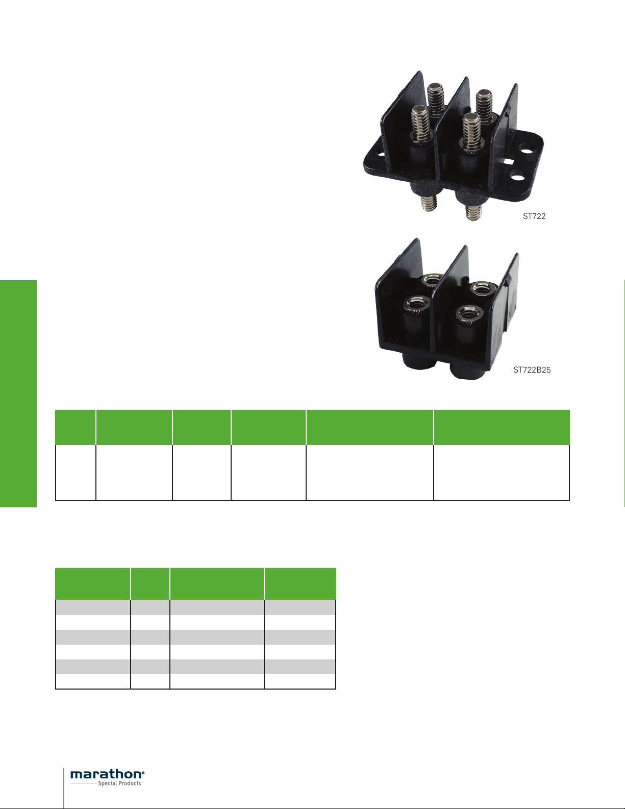
STUDDED FEED-THRU
TERMINAL BLOCKS
ELECTRICAL:
Volts / amps - see table
Wire range is determined by the compression lugs used
Short circuit current rating (SCCR) of 10K
Factory and field wiring
STANDARDS:
UL 1059 recognized file no. XCFR2.E62806
CSA certified file no. LR19766 (CSA C22-2 No. 158)
CE (Component IEC 60947-7-1)
RoHS compliant (All)
WEBSITE RESOURCES:
Detailed product data sheets
• Material information
• Termination & mounting specifications
• Multiple wire rating specifications
• Detailed SCCR information
Dimensional drawings & 3D CAD files
Accessories available
ST715S1902
ORDERING CODE:
VOLTS AMPS SERIES
300 80 ST715S19xx
600 380 ST723B38xx
POLES
(xx)
02
01/02
ST723B3802
HARDWARE OPTIONS
Blank – No hardware
UH – All nuts shipped bulk
AH – All nuts assembled
DL – Assembled barrier side, remainder shipped bulk
Blank – No hardware
UH – All nuts shipped bulk
AH – All nuts assembled
DL – Assembled barrier side, remainder shipped bulk
24

SINGLE STUD CONNECTION
TERMINAL BLOCKS
ELECTRICAL:
300 volts AC/DC (UL)
Designed for two or more wire terminals
STANDARDS:
RoHS compliant (All)
WEBSITE RESOURCES:
Detailed product data sheets
• Material information
• Termination & mounting specifications
Dimensional drawings & 3D CAD files
Accessories available
ORDERING CODE:
CATALOG #
ST 710 31 Black
ST 710 31 RED Red
ST 710 38 Black
ST 710 38 RED Red
INSULATOR
COLOR
ST 710 38
STUD SIZE
5/16”
5/16”
3/8”
3/8”
ST 710 31 RED
25

MOTOR (IEC STYLE)
TERMINAL BLOCKS
ELECTRICAL:
Amps - see table
250 - 1100 volts
Designed for delta and WYE wiring configurations
For use with listed crimp lugs
STANDARDS:
UL 1059 recognized file no. XCFR2.E62806
CSA certified file no. LR19766 (CSA C22-2 No. 158)
CE compliant - UL investigated to IEC 60947-7-1, file no.
XCHG2.E243117, IEC 60947-7-1
UL investigated to SANS 1804-2
RoHS compliant (All)
WEBSITE RESOURCES:
Detailed product data sheets
• Material information
• Termination & mounting specifications
• Multiple wire rating specifications
• Detailed SCCR information
Dimensional drawings & 3D CAD files
Accessories available
ST750M12
(Two Piece Style)
ST750M8
(One Piece Style)
CATALOG #
ST755M4 M4
ST750M4 M4
ST755M5 M5
ST750M6 M6
ST750M8 M8
ST755M10 M10
ST755M12 M12
ST750M12 M12
ST750M16 M16
All blocks include links and hardware assembled
STUD
SIZE
STYLE
One
Piece
One
Piece
One
Piece
One
Piece
One
Piece
One
Piece
One
Piece
Two
Piece
Two
Piece
AMPS VOLTAGE
cURus IEC cURus IEC
38 50 300 630 250 #8 - #18 AWG 55 x 33 x 43
35 50 1000 1000 110 0 #8 - #18 AWG 63 x 37 x 42
50 50 600 800 660 #8 - #16 AWG 68 x 40 x 45
101 121 1000 1000 110 0 #2 - #14 AWG 85 x 50 x 62
160 185 1000 1000 110 0 2/0 - #12 AWG 112 x 69 x 76
185 217 1000 1000 110 0 3/0 - #8 AWG 140 x 86 x 91
242 271 1000 1000 110 0 250 kcmil - #8 AWG 170 x 110 x 97
315 3 74 1000 1000 110 0 400 kcmil - #8 AWG 179 x 167 x 107
560 520 1000 1000 110 0
Sans
1804
WIRE RANGE
(2) 300 kcmil -
(2) #2 AWG
OVERALL
DIMENSIONS
(L x W x H) MM
201 x 191 x 133
26
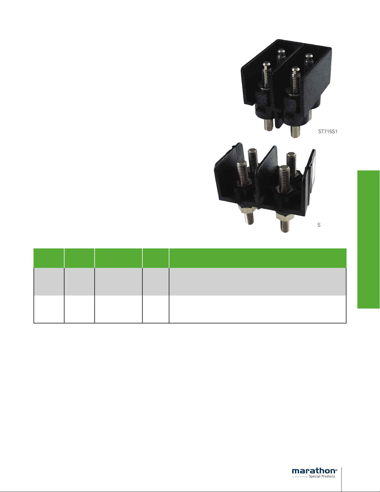
GROUNDING LUGS & CONNECTORS
TERMINAL BLOCKS
ELECTRICAL:
See table
STANDARDS:
UL recognized file no. ZMVV2.E43665 (excludes KT375)
Supplemental UL Certification: Grounding and bonding equipment (KDER)
CSA certified file no. 63510-25
Green screwhead for ID (GLxx’s only)
RoHS compliant (all)
WEBSITE RESOURCES:
Detailed product data sheets
• Material information
• Termination & mounting specifications
Dimensional drawings & 3D CAD files
Accessories available
CATALOG # WIRE RANGE AWG/kcmil MOUNTING HOLE DIAMETER
#2 - #3 .27
GL02*
(9807052)
*For hex drive screw, catalog number is GL02IH
#4 - #6 .27
#8 .27
#10 - #14 .27
CATALOG # WIRE RANGE AWG/kcmil MOUNTING HOLE DIAMETER
GL20
(9818102)
CATALOG # WIRE RANGE AWG/kcmil MOUNTING HOLE DIAMETER
GL35
(9819830)
CATALOG # WIRE RANGE AWG/kcmil MOUNTING HOLE DIAMETER
WC12044
(9740701)
CATALOG # WIRE RANGE AWG/kcmil MOUNTING HOLE DIAMETER
WC12064
(9797110)
2/0 - #6 .41
#8 .41
#10 - #14 .41
350 kcmil - #6 .53
(1) 2/0 - #14
(4) #4 - #14
(1) 2/0 - #14
(6) #4 - #14
.21
.21
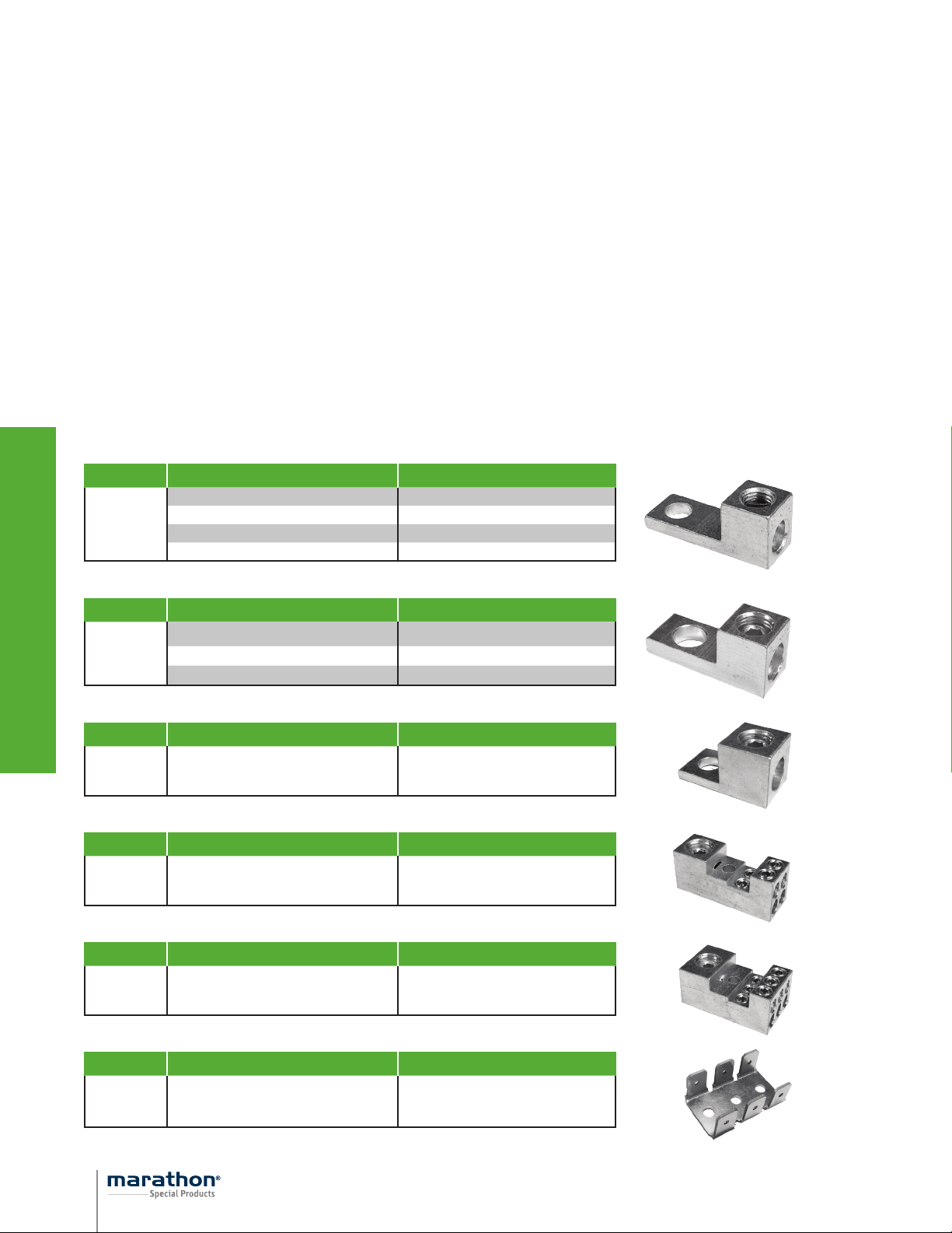
CATALOG # WIRE RANGE AWG/kcmil MOUNTING HOLE DIAMETER
KT375 1/4” Quick-connect .13
27
 Loading...