

Marathon Special Products 135X704 Data Sheet
Product Data Sheet
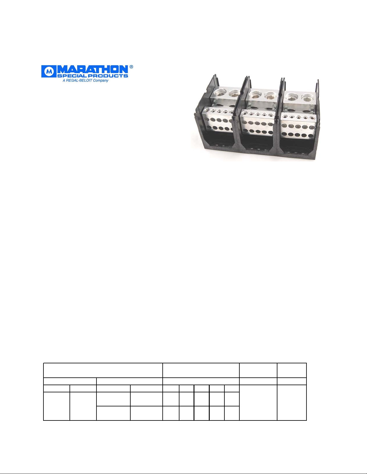
135X704
Power Distribution Block
UL Listed
Category QPQS
950 Amps, 600 Volts (AC/DC)
Provides Feeder Circuit Terminal Spacing up to 600 Volts per UL 508A, Section 10.
Wire Range:
Line Side: (2) 750kcmil – 1/0 AWG
Load Side: (10) 2/0 kcmil – 14 AWG
See tables below for SCCR wire ranges, flexible stranded and multiple wire approvals.
Electrical Ratings:
• 950A copper wire, 770A aluminum wire (Based on NEC Table 310-16, 75°C columns)
• UL Voltage Rating: 600 Volts AC/DC (UL 1953)
• Factory and Field Wiring
Agency Certifications:
• UL Listed, Investigated to UL 1953, File QPQS.E309401
• RoHS Compliant
Short Circuit Current Ratings:
SCCR Rating applies for Copper Stranded wire only
UL Class B, C (known as Rigid Stranded, Building Wire, Code Wire)
UL Class G, H, I (Flexible Stranded, includes DLO)
Suitable Conductors (kcmil/AWG)
Copper, S t randed
Line Load
Size Class Size Class J T RK1 RK5 G
750 - 1/0 B,C 1 - 2 G, H, I 100,000 600
535-1/0 G, H, I 2/0 - 6 B,C
For DC power or any wire combinations or Overcurrent Protection not shown- SCCR is
10,000A
2/0 - 2 B,C
1 - 6 G, H, I
Overcurrent Protection
Class/ M ax Amp Rating
600
600 700
300
300 200
200
1006060
SCCR, RMS Vo lts
SYM Amps Max
m
m
3
6
m
6
q
Minimum Enclosure Size: 20” x 24” x 8” (3840 cu. In)
Mechanical Ratings:
• Maximum insulator base temperature: 125°C (257°F) UL RTI
• Flammability rating of insulator base: UL 94 V-0
Materials:
• Connector: High conductivity aluminum, tin plated
• Insulator base: Glass filled polycarbonate (thermoplastic)
• Terminal screws: Aluminum, tin plated
• Connector mounting screw: Steel, zinc plated
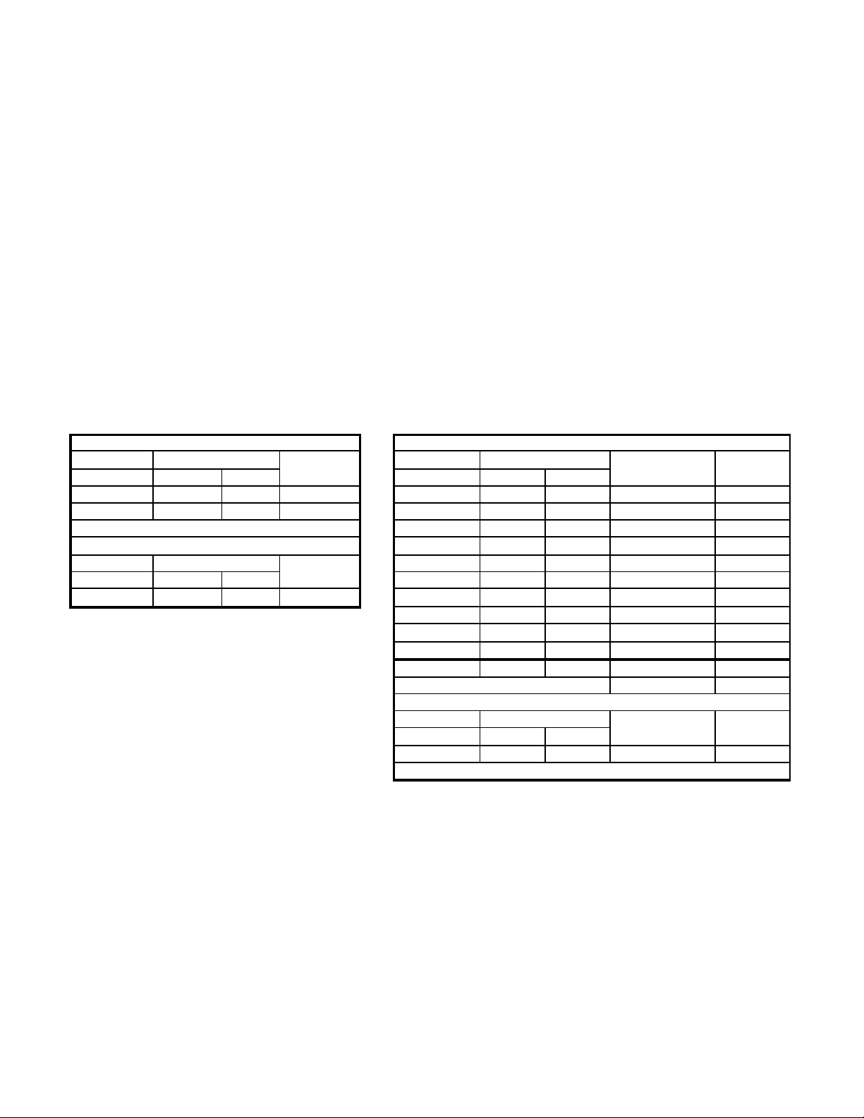
Wire Ranges, Wire Types, Torque Ratings: 135X704
UL Class B, C (known as Rigid Stranded, Building Wire, Code Wire)
UL Class G, H, I (Flexible Stranded, includes DLO)
Line Side 2) 750 kcmil - 1/0 AWG Load Side 10) 2/0 - 14 AWG
Copper Condu c torCopper Condu c tor
W ire S ize To rque W ire S ize To rque No. P e r
kcmil - AW G N.
750 - 1/0 67.8 600 B, C 2/0 13.6 120 B, C 1
53 5 - 1/0 67.8 60 0 G,H, I 1/0 13.6 120 B,C 1
Aluminum Conductor
W ire S ize Torque
kcmil - AW G N.
750 - 1/0 67.8 600 Stranded 6 13.6 120 B, C, G, H, I 1
in. lbs UL Class kcmil - AW G N.
1 13.6 120 B, C, G, H, I 1
2 13.6 120 B, C, G, H, I 1
13.
in. lbs Type
413.
8 13.6 120 B, C, G, H, I 1
10 5.6 50 B, C, G, H, I* 1
12 5.6 50 B, C, G, H, I* 1
14 5.6 50 B, C, G, H, I* 1
Wire Size Tor
kcm il - AWG N.m in . l bs Type Opening
2 /0 - 6 31.0 120 Stranded 1
in . l bs UL Clas s O pening
120 B, C, G, H, I 1
120 B, C, G, H, I 1
*Also Solid Cu 1
Aluminum Conductor
ue No. Per
Installation:
• Wire strip length, line and load side tap – 1 ¾”
• Wire strip length, load side tap, top row – 7/8” bottom row – 1 7/8”
• Panel mountable: recommended fastener (4) per pole, ¼ “ or 6mm
Torque to 30 in. lbs. (3.4 N.m)
Line Side 750 kcmil wire opening- diameter 1.125” (28.5 mm)
Load Side wire opening 2/0 AWG – diameter .438” (11.1 mm)
 Loading...