

Marathon Power TRTC-2002-N1 Maintenance Manual


2

TABLE OF CONTENTS
3
BEFORE YOU START: SAFETY ................................................................ 6
Safety Symbols ............................................................................................... 6
Before Getting Started .................................................................................... 7
System Safety Checklist ................................................................................. 7
Battery Safety Checklist .................................................................................. 8
Stand-By Generator ........................................................................................ 8
Future Servicing .............................................................................................. 9
SECTION 1: GLOSSARY ....................................................................... 10
SECTION 2: THEORY OF OPERATION .................................................... 11
Intro ............................................................................................................... 11
2.1 The Advantages ...................................................................................... 11
2.2 System Description ................................................................................. 12
SECTION 3: A TOUR OF YOUR TRTC-2002-N1 .................................... 13
3.1 Front and Back Panel ............................................................................. 13
3.2 Power Transfer Switch ............................................................................ 18
SECTION 4: INSTALLATION .................................................................. 19
Warnings & Tips ............................................................................................ 19
4.1 Mounting ................................................................................................. 19
4.2 Recommended Wiring ............................................................................ 20
4.3 Connecting the Output or Signal Cabinet ................................................ 24
4.4 Connecting the Utility Line Input Power .................................................. 25
4.5 Starting Up the UPS ................................................................................ 26
4.6 Testing the UPS ...................................................................................... 27
4.7 Shutting Down the UPS .......................................................................... 28
4.8 Emergency Shutdown ............................................................................. 29
4.9 Removing the PTS .................................................................................. 30
SECTION 5: OPERATION – LCD INTERFACE ......................................... 31
5.1 Interface Directory ................................................................................... 31
5.2 Menu Tree and Main Screen ................................................................... 32

5.3 Using the LCD Interface .......................................................................... 34
4
5.6 Operating Modes .................................................................................... 35
5.7 Status ...................................................................................................... 37
5.8 Control .................................................................................................... 38
5.9 Settings ................................................................................................... 39
5.10 Maintenance .........................................................................................40
5.11 Alarm Menu ........................................................................................... 41
5.12 Fault Menu ............................................................................................ 42
5.13 Events Log ............................................................................................ 43
SECTION 6: OPERATION – RS-232 / USB INTERFACE ........................... 44
6.1 Interface Directory ................................................................................... 45
6.2 Menu Tree ............................................................................................... 46
6.3 RS-232 / USB Interface Information ........................................................ 49
6.4 Main Menu .............................................................................................. 51
6.5 Submenus ............................................................................................... 53
6.6 Unit Specifications .................................................................................. 53
6.7 Input / Output Values .............................................................................. 53
6.8 Maintenance ........................................................................................... 53
6.9 Line Slow Detection Parameters ............................................................. 56
6.10 Parameter Change Procedure .............................................................. 56
6.11 Parameter Descriptions......................................................................... 57
SECTION 7: OPERATION – WEB INTERFACE .......................................... 58
7.1 Web Interface Directory ...........................................................................58
7.2 Web Interface .......................................................................................... 58
SECTION 8: ADJUSTMENTS ................................................................. 61
8.1 Back-Up Test .......................................................................................... 61
8.2 Sense Mode - Normal and Generator Waveforms .................................. 62
SECTION 9: MAINTENANCE ................................................................. 63
9.1 Trouble Analysis ..................................................................................... 63
9.2 TRTC-2002-N1 Troubleshooting ............................................................. 64
9.3 PTS Troubleshooting .............................................................................. 65

9.4 Troubleshooting Sequence Chart ........................................................... 66
5
9.5 Alignment Procedure – Battery Backup Test .......................................... 67
9.6 Preventative Maintenance....................................................................... 68
9.7 Battery Maintenance ............................................................................... 68
APENDICES ....................................................................................... 70
TRTC-2002-N1 Specifications ...................................................................... 70
PTS Specifications ........................................................................................ 72
Battery Care .................................................................................................. 73
HyperTerminal Set-Up .................................................................................. 74
HyperTerminal at a Glance ........................................................................... 76
PuTTY at a Glance ....................................................................................... 77
Step by Step Connecting to Windows XP ..................................................... 78
Step by Step Connecting to Windows 7 ........................................................ 82
Return Instructions .......................................................................... 86

Before You Start: Safety
Indicates presence of DANGEROUS VOLTAGE in the area.
Extreme caution should be used.
Indicates ATTENTION to important operating instructions.
Follow them as indicated.
DANGER!
ATTENTION!
NOTE / TIP:
Indicates additional information to assist the completion of a procedure or tips for
ease of operation.
*SAVE THESE INSTRUCTIONS*
6
IMPORTANT SAFETY INSTRUCTIONS ARE CONTAINED IN THIS MANUAL
To reduce the risk of electrical shock and to ensure the safe operation of the TRTC-2002-N1, the
important safety instructions are marked with the symbols as shown below. These symbols are
used throughout this manual and wherever they appear, it indicates that the instructions should
only be carried out by qualified personnel.
Safety Symbols
Before Getting Started
System Safety Checklist
Battery Safety Checklist
Stand-By Generator
Servicing
Safety Symbols

Before Getting Started
Do not expose the TRTC-2002-N1 to rain or moisture.
Total Earth ground leakage current of loads connected to the TRTC-2002-N1 should not exceed 2.4 mA.
The TRTC-2002-N1 generates, uses and can radiate radio frequencies if not installed and tested in
accordance with the instructions contained in this manual. It has been tested and found to comply with
the limits established for a Class A computing device pursuant to part 15 of FCC rules when it is operated
alone. It also complies with the radio interference regulations of DOC, which are designed to provide a
reasonable protection against such interference, when this type of equipment is used in a commercial
environment. If there is interference to radio or TV reception, which is determined by switching it on and
off. Relocate the equipment or use an electrical circuit other than the one used by the TRTC-2002-N1.
DANGER!
DANGER!
DANGER!
Sealed lead-acid batteries with high energy and chemical hazards are used. This
manual contains important operation and safety instructions.
DANGER!
7
IMPORTANT SAFETY PRECAUTIONS
Only qualified personnel should service or supervise the service of the TRTC-2002-N1.
System Safety Checklist
• Carefully unpack the TRTC-2002-N1. Report any shipping damage at once.
• Read this manual. If you have any questions about safe installation, operations or
maintenance of the system, contact manufacturer service department.
• Before installation, confirm that the voltage and current requirements of the load(s) are
compatible with the system’s output. Confirm that the line voltage and current is
compatible with the system’s input requirements.
• The system should be installed on a dedicated power circuit.
• Use proper lifting techniques when moving system.
• The TRTC-2002-N1 has more than one live circuit. It is fed from AC as well as battery
power. Power may be present at the output(s) even if the system is disconnected from
line power.
• When installing a system in other than a Manufacturer cabinet, ensure that the
environment meets the system specifications shown in the Appendix.

Battery Safety Checklist
DANGER!
NOTE:
8
High & dangerous voltages are present inside the system. Only qualified personnel
should perform installation and maintenance.
Live battery wires must not touch the TRTC-2002-N1 chassis or any other metal objects.
This can cause a fire or explosion.
Inspect the batteries once a year for signs of cracks, leaks, or swelling. Replace as
needed.
When batteries are in storage, charge them at least once every three months for
optimum performance and to extend their lifetime.
Always replace batteries with the ones of identical type and rating. Never install old or
untested batteries. Never mix old with new batteries. Never mix the different amp hour
rated batteries within one system.
Use insulated tools during servicing.
Remove all rings, watches, jewelry, or other conductive items before working inside the
enclosure.
Follow local regulations for the disposal of batteries. Recycling is the best method.
Never burn batteries to dispose of them. They may explode.
Do not open the batteries. The contents are toxic.
Stand-By Generator
If the TRTC-2002-N1 constantly switches between Battery and Line modes because of
line fluctuations, the input parameters should be broadened from Normal to Generator
(See Section 8.2 “Sense Mode - Normal and Generator Waveforms”).
In generator mode, the acceptable range of input frequency and voltage is expanded to
accommodate the voltage and frequency fluctuations created by a generator or a power
source of such kind.
Use a generator with electronic speed and voltage controls which typically produces Total
Harmonic Distortion in % (THD) of less than 10%. Generators with mechanical governors
can force the system to run continuously in Battery mode.
Before installation, compare the generator’s output voltage to the TRTC-2002-N1’s input
voltage requirements as listed on both nameplates. To insure the system’s smooth operation,
use a generator capable of supplying 2X or twice as much power as required by the total
load.

SAVE THE ORIGINAL SHIPPING BOX
9
When returning the TRTC-2002-N1 for servicing, use the original shipping box with the
supplied Styrofoam protectors. Manufacturer is not responsible for damage caused by
improper packaging of returned systems.
READ THE OPERATOR’S MANUAL
Before installation, become familiar with the TRTC-2002-N1 by reviewing the procedures
and drawings in this manual. If you have any questions about safe installation, operation, or
maintenance, contact Manufacturer customer service department.
Complete the following for records & future servicing:
Model No.: TRTC-2002-N1________________ _
Serial No.: ___________________________________
(Above items can be found on the nameplate label attached to the side of the unit)
Products Sales Order No.________________________
TRTC-2002-N1 P/N: ___________________________
Purchase Order No.:____________________________
Purchased from: _
(Following details are for installation location)
Installation date: _
Installed by: _
City: _
State/Province: _
Zip/Postal Code: _
Country: _
Telephone #: ____________________________________________
Fax #: _
E-Mail: ________________________________________
Street names of location: _________________________
Cabinet / controller type: _________________________

Section 1: Glossary
AC
ANSI
AWG
BBS
E-BBS
DC
IEEE
EIA
ITE
KVA
LED
LCD
NEMA
NC
NO
OD
PTR
UL
TB
THD
UV
VDC
VA
VAC
Alternating Current
American National Standards Institute
American Wire Gage
Battery Backup System
External Battery Backup System Cabinet
Direct Current
Institute of Electrical and Electronics Engineers
Electronic Industries Association
Institute of Transportation Engineers
Kilovolt-Ampere
Light Emitting Diode
Liquid Chrystal Display
National Electrical Manufacturers Association
Normally Close
Normally Open
Outside Diameter
Power Transfer Relay
Underwriters Laboratories
Terminal Block
Total Harmonic Distortion
Ultraviolent Light
Volts DC
Voltage Ampere
Voltage Alternating Current
10

Section 2: Theory of Operation
11
Intro
2.1 The Advantages
2.2 System Description
The traffic signal cabinet is powered continuously when a TRTC-2002-N1 system is
installed. The system allows connection for the normal utility power using standard terminal
blocks or an optional generator power via standard 30 Amp (optional 50 Amp) generator
receptacle. The optional bypass switch redirects utility power to the load and allows the TRTC2002-N1 to be removed for service on a temporary or permanent basis without disrupting the
operation of the traffic signal.
With a fully functioning UPS system, the PTS allows utility power to flow out to the traffic
cabinet, when the utility line is qualified (within the acceptable range as programmed). If the
UPS is not functioning, the PTS will bypass the UPS allowing the utility to flow out to the
traffic cabinet. The UPS input is protected with one circuit breaker located on the PTS as well
as another one located on the UPS module. When the UPS internal BOOST and BUCK is
enabled, the PTS is activated allowing UPS to continuously boost the output when input is
lower, buck or lower the output when input is higher or run from batteries when input power
is outside the specified acceptable range. The PTS has dual NEMA power receptacles for
optional battery heating pads, connecting a vacuum cleaner, or a PC for maintenance.
The smart, temperature compensated internal charger continuously monitors and maintains
the batteries in a fully charged state. For the protection of the battery, the charging process is
automatically discontinued when the battery temperature exceeds 50 degrees C. When the
batteries are fully charged, the smart charger provides a continuously pulsating ON-OFF
trickle charge to keep the batteries topped-off or fully charged. When input power is not
qualified or is outside the acceptable range, the UPS derives the DC power from the storage
tank of four batteries connected in series and maintains output power until the batteries are
depleted down to a specified level or the utility power returns within its specified levels. The
traffic intersection will continue to operate in full operation AND / OR in flash mode as
programmed by the user. Programmable contacts allows the user to place the intersection
in flash mode as soon as the input power is lost or after the batteries are depleted down to
a certain capacity that is determined and programmed by the user. The amount of back-up
time battery power can provide depends on the Amp-hour capacity of the batteries as well
as the intersection watt load that requires support.
2.1 The Advantages
Advanced Power Protection Technology
TRTC-2002-N1 is an Uninterruptible Power Supply (UPS) also known as a Battery
Backup System (BBS) designed for both indoor and outdoor applications. The TRTC2002-N1 provides continuous power to traffic and signal equipment.
♦ Advanced Communications
The RS232 and/or USB ports allow for local or remote monitoring of the TRTC-2002-N1.

♦ Smart Charging
Simplified TRTC-2002-N1 System Block Diagram
12
MP Series smart charge technology ensures the batteries are always at peak performance.
♦ User Friendly Supervision
The LCD panel provides “At a Glance” monitoring and control.
♦ Service Friendly
The batteries can be changed without shutting down the intersection loads or the TRTC2002-N1.
2.2 System Description
Purpose: Describes the operation of the TRTC-2002-N1 System.
The TRTC-2002-N1 System provides backup power to traffic control signal equipment. It
consists of the PB2000 Uninterruptible Power Supply (UPS) System, the Power Transfer
Switch (PTS), and batteries that provide back-up power when the line is unqualified. These
three components can be mounted inside an enclosure to provide protection from most
weather conditions.
Section 3: A Tour of Your TRTC-2002-N1
4
2
1
3
TRTC-2002-N1 Front Panel
13
3.1 Front Panel
3.2 Power Transfer Switch
3.1 Front Panel
Purpose: Describes the display, connections and switches on the TRTC-2002-N1 front
TRTC-2002-N1 )URQW Panel
panel.
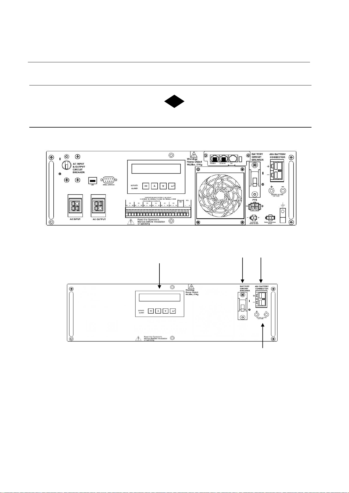
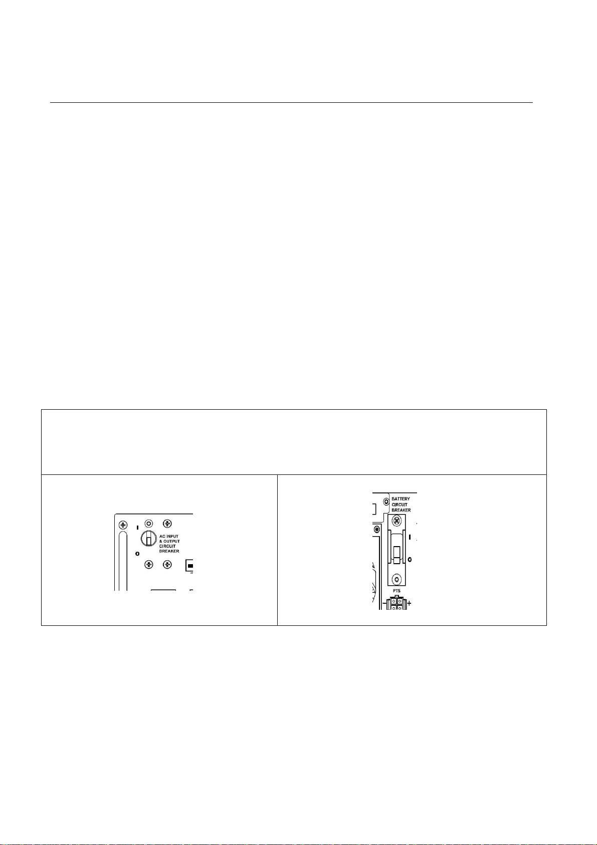
1. 48VDC Battery Connector
Connects the battery to the unit. The battery string voltage is 48VDC.
2. Battery Circuit Breaker
Acts as an ON/OFF switch for battery power. Must be in the ON position for normal
operation.
3. Battery Voltage Test Points
Battery voltage can be measured at these Test Jacks only when the battery circuit
breaker is turned ON.
F
TEST JACKS ARE NOT DC POWER OUTLET TERMINALS.
7
6
5
TRTC-2002-N1 Front Panel
8
NOTE:
14
4. Liquid Crystal Display (LCD) Control Panel
The UPS can be controlled and monitored via this LCD panel. See Section 5 for further
information.
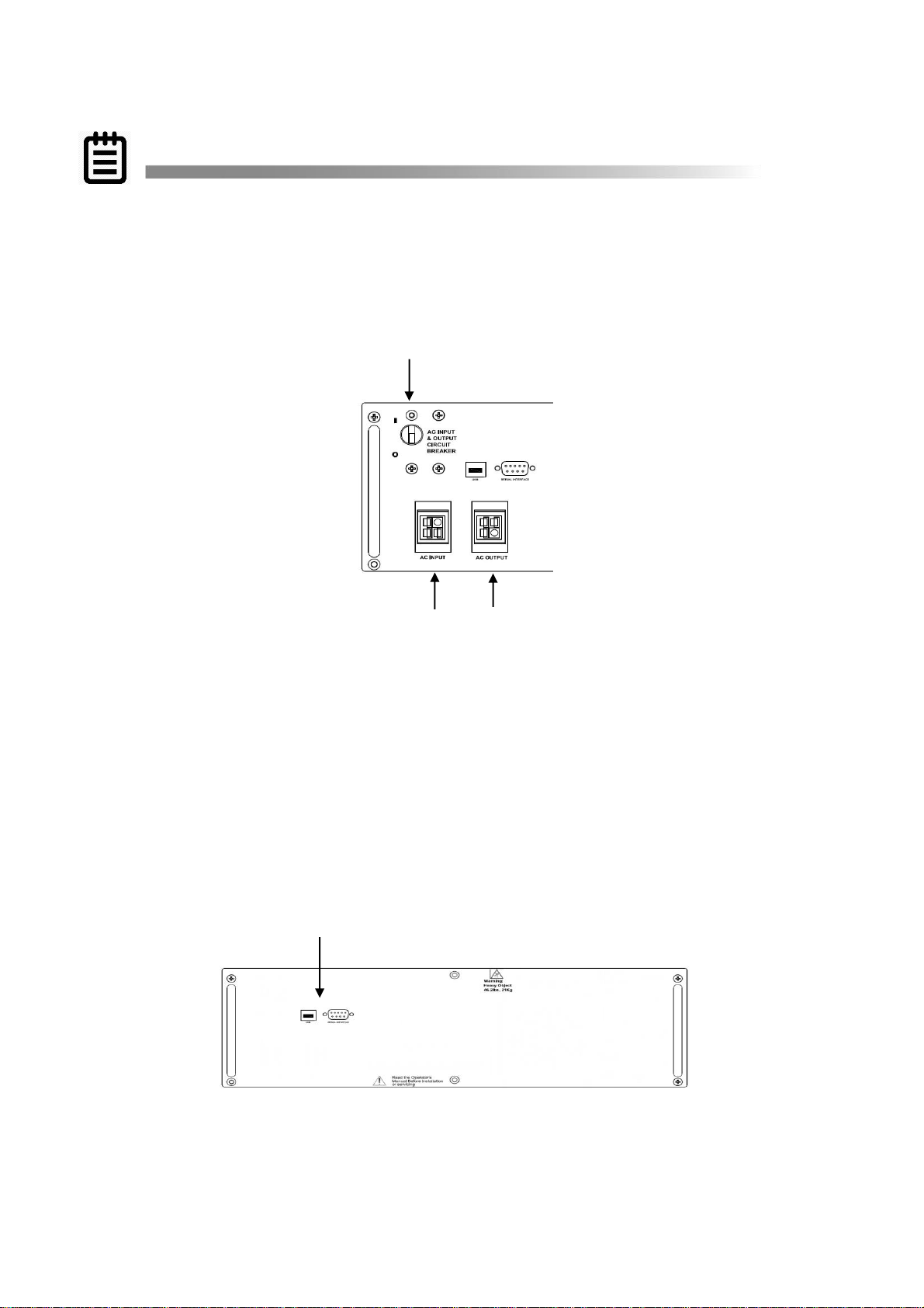
5. AC Input & Output Circuit Breaker
Acts as a line and output power ON/OFF switch to facilitate the unit’s maintenance or
replacement. Must be in the ON position for normal operation.
6. AC Input
Inlet Anderson PP45/4P provided for the input of line power.
7. AC Output
Outlet Anderson PP45/4P provides the connection for the output of line power.
TRTC-2002-N1 Front Panel
8. USB / Serial Interface / RS232 Connector
The USB and /or DB-9 female connector is used to connect the TRTC-2002-N1 to the
host computer for remote control, monitoring and calibration via RS232 commands.
For the USB or DB-9 female RS232 connections use computer industry standard
9
NOTE:
15
computer cable between the computer’s USB or RS232 port and the TRTC-2002-N1
unit’s USB or RS232 ports.
See Section 4 for more details about connection and use.
TRTC-2002-N1 Front Panel
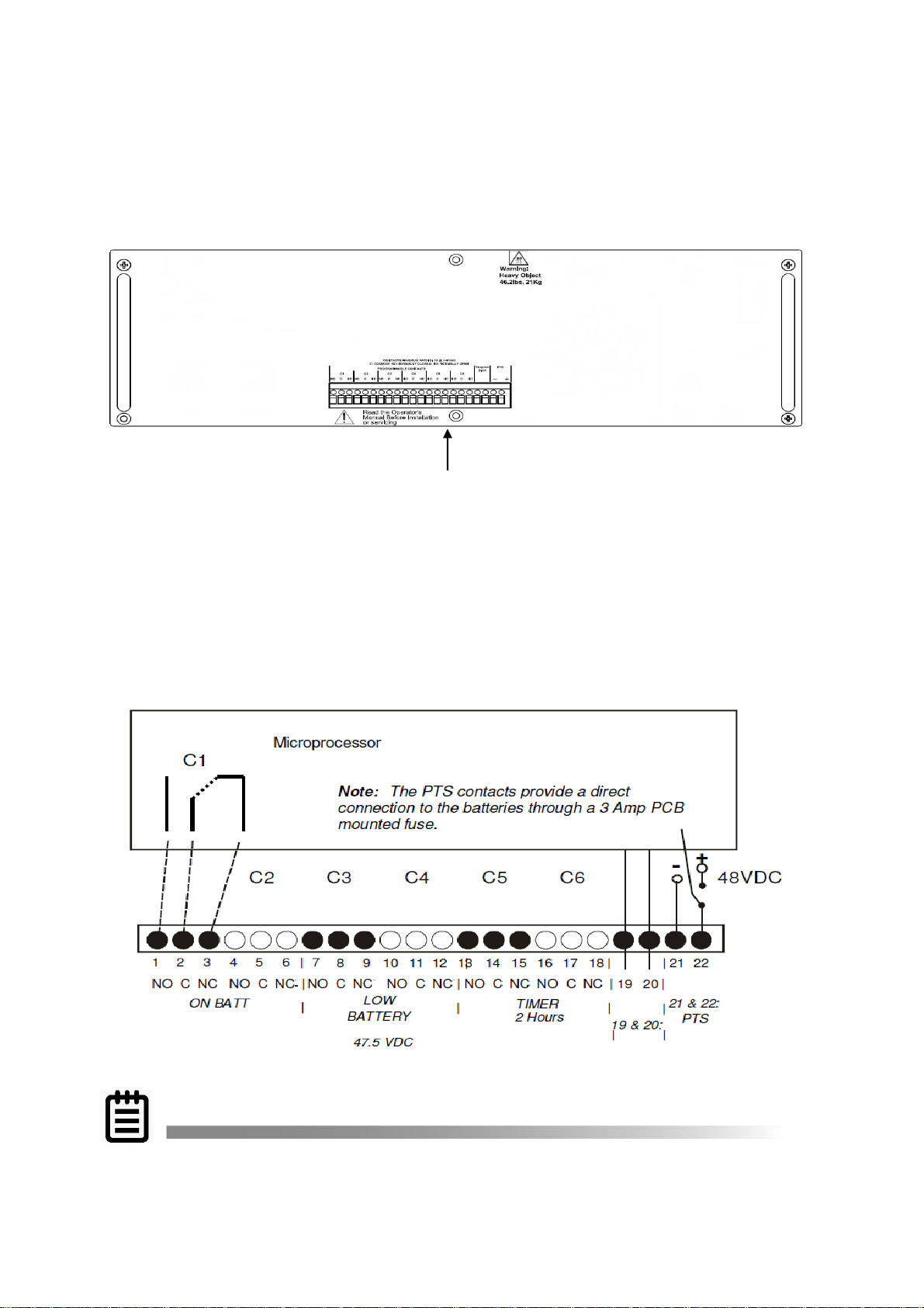
9. Green Control Terminal Block
This 22 position terminal block provides communication with the intersection controller,
controls the Power Transfer Switch (PTS) and Programmable Input contact. Figure below
shows its layout and operation.
Green Terminal Block
This terminal block is opto-isolated and shares a common ground with the serial
interface. Each of the six programmable contacts can be programmed for one or
more functions such as: The Timer, Low Battery and On Batt. The relay contacts
are Form C type, i.e. each of the six programmable contacts has Common (C);

Normally Closed (NC) and Normally Open (NO) contact position.
TIP:
NOTE:
NOTE:
16
• On Batt: This relay energizes when Utility Input line power is unqualified.
• IMPORTANT: When the AC input and output circuit breaker is turned OFF, an auxiliary
switch of the circuit breaker opens which disables the On Batt. contact at the Green
Control Terminal Block. This prevents the intersection lights from flashing.
• Low Battery: These relays energize when the battery drops below the programmed
battery capacity. The default value is 47.5VDC or 40% battery capacity.
You can change the preprogrammed value to match the batteries used and the
actual operating conditions. See Section 9.7 Battery Maintenance.
• Timer: These relays energize after the unit has been in Battery mode for the
programmed time period. The factory default value is 2 hours. The time can be
programmed to be from 15 min. to 8 hours in 15 minute increments.
• Program Input: The programmable input contact can be programmed for one function
such as: Self-test, EXT Alarm, EXT Battery Alarm, EXT Fan Failure, Door Interlock.
Jumper the TB 19 & 20 on the Green Control Terminal Block and the program alarm
will show on LCD display.
• PTS: TRTC-2002-N1 sends a 48VDC signal from the batteries to the PTS, which
activates the PTS, resulting in transfer from Input power to BBS power. See Section
1.3, Wiring, of this manual for connection instructions.
These contacts have a maximum rating of 1 Amp at 120V. Only the first On Batt contact
is illustrated. The remaining 5 contacts for Low Battery, Timer, etc. are similar.
1) 6 sets of programmable contacts have the following factory default settings:
C1, C2 = “On Batt”
C3, C4 = “Low Batt @ 47.5VDC”
C5, C6 = “Timer @2.00 Hours”
2) User may program each of the six contacts for one or more functions.
13
12
10/11
14
NOTE:
NOTE:
17
TRTC-2002-N1 Front Panel
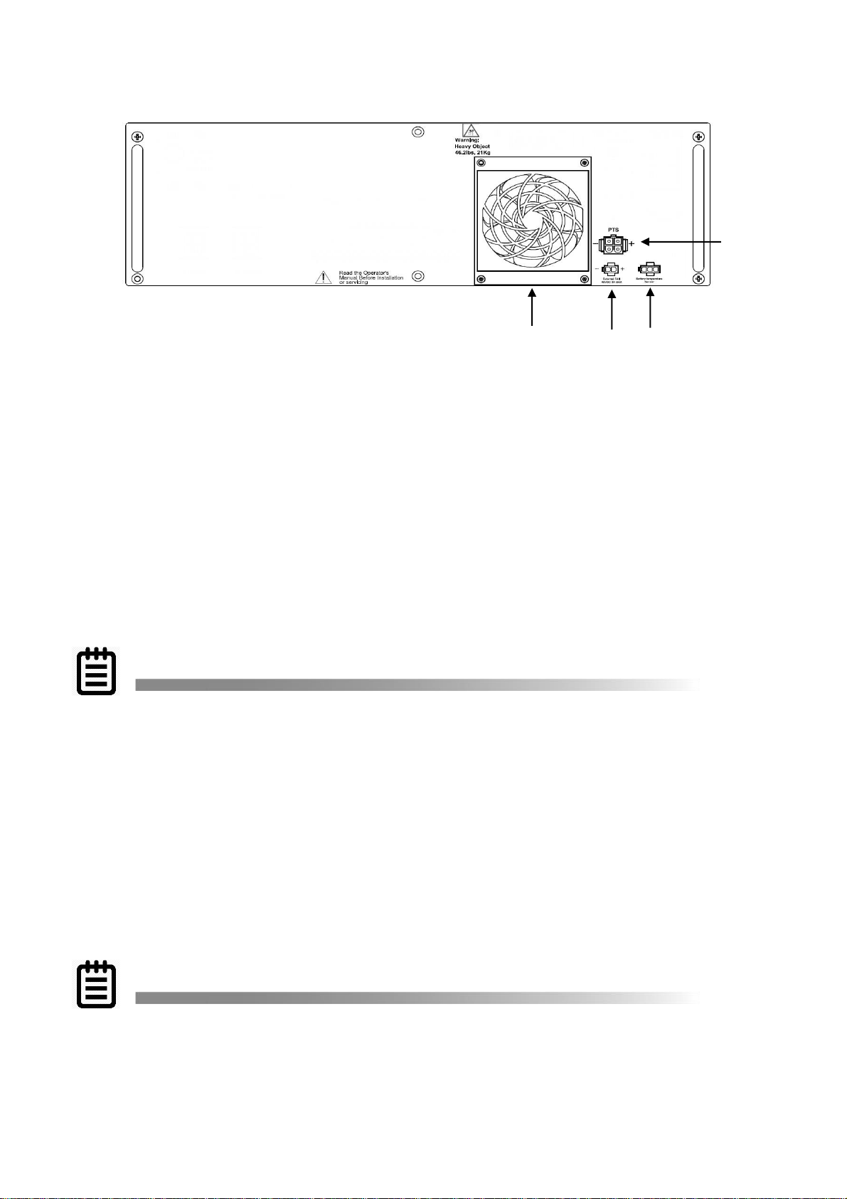
10. Battery Temperature Sensor Strain Relief
This secures the Battery Temperature Sensor cord to the panel and prevents
connector disconnection during an earthquake or other severe vibrations.
First plug the sensor cable into the connector. Then use one of the ties provided in the
mounting kit to attach the sensor cord to the strain relief loop. Ensure that the cable is
secure.
11. Battery Temp Sensor
It attaches the battery temperature probe to the unit for monitoring battery temperature.
The charging voltage is temperature dependent. The microprocessor of the smart
charger adjusts the voltage for optimum charging.
The temperature probe connector must be plugged in for normal operation. The
sensor end should be firmly attached to the terminal of the battery.
If the TRTC-2002-N1 is not charging the batteries check the temperature probe. To
test the temperature probe unplug it from the face of the UPS. Check the resistance
of the temperature probe by inserting the probes of an ohm meter into the top and
bottom pins of the connector. The meter should read approximately 12,000 Ohms at
25°C (77 °F). If resistance is not in this range, replace temperature probe.
12. Ext Fan 48VDC
Provides DC Power (48VDC, 1 Amp (Max)), which could be used to power an optional
48VDC fan, mounted inside the enclosure for regulation of the interior temperature.
13. Internal Fan
This microprocessor-controlled fan regulates the unit’s internal temperature. It must
not be blocked. The filter in front of the fan is removable for cleaning.
Inspect the filter every 6 months, or as often as required. Clean by removing it,
running water through the filter and air-drying before reinstallation.
14. PTS Connector
The PTS Connector connects the TRTC-2002-N1 to the PTS via the Bypass control
wires.
3.2 Power Transfer Switch
4
2
3
1
5
6
7 8 9
18
The Power Transfer Switch (PTS) shown below allows the UPS to be removed for service,
replacement or maintenance without interrupting power to the traffic cabinet.
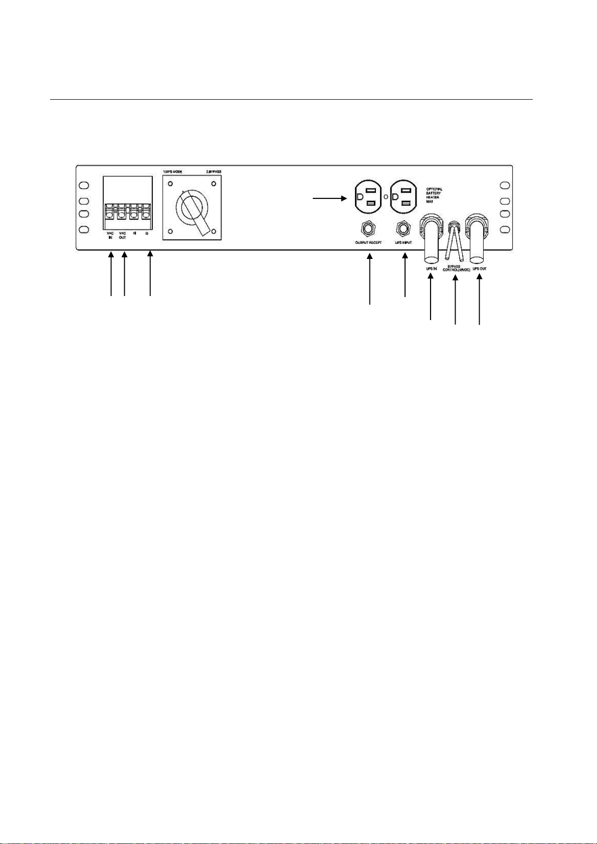
Power Transfer Switch Front Panel
1. The wires from the neutral and ground bus of the traffic cabinet are connected to this
terminal block.
2. The Input line power is connected to the terminal block marked with “AC INPUT”.
3. The Output line power is connected to the terminal block marked with “AC OUTPUT”.
4. An optional surge suppressor, external PC, optional battery heater or a vacuum
cleaner for maintenance may be plugged into these receptacles.
5. This “UPS OUT” cord is connected to the OUTPUT AC terminal block on the TRTC-
2002-N1.
6. The Black and Red PTS control wires are connected to the PTS connector on the
TRTC-2002-N1.
7. This “UPS IN” cord is connected to AC INPUT terminal blocks on the TRTC-2002-N1.
8. This circuit breaker provides input power protection for the TRTC-2002-N1.
9. The dual receptacles are protected by this circuit breaker.
Section 4: Installation
DANGER!
TIP:
19
Warnings & Tips
4.1 Mounting
4.2 Recommended Wiring
4.3 Connecting the Output or Signal Cabinet
4.4 Connecting the Utility Line Input Power
4.5 Starting Up the UPS
4.6 Testing the UPS
4.7 Shutting Down the UPS
4.8 Emergency Shutdown
4.9 Removing the PTS
If this is a new traffic signal installation with Utility AC power going directly to UPS,
make sure the upstream circuit breaker feeding the Utility Power is OFF before
beginning this step. If this is addition of a UPS to an existing traffic signal cabinet, DO
NOT terminate the power cable from the signal cabinet to the UPS at the signal cabinet
end until the final step after all other connections have been completed. This will
minimize the length of time the traffic signals must be off for final power connection.
There are many different ways that the Utility AC can be wired into the traffic signal
cabinet. The intent of this manual is only to explain proper connection of utility AC at
the UPS end of the cable. How the Utility AC is routed from the service entrance or
through the traffic signal cabinet (hereafter referred to as the “power source”) to the
UPS shall be determined by a licensed electrician in accordance with local electrical
codes.
The suggested method of wiring Utility AC to the UPS from the traffic signal cabinet is
to connect the UPS at the traffic cabinet after the main cabinet breaker and surge
suppressor so that the UPS is also protected by the cabinet surge suppressor.
4.1 Mounting
Purpose: Describes how to mount the TRTC-2002-N1 System into an enclosure.
The TRTC-2002-N1 components can be mounted inside an existing NEMA or 332 or various
other traffic cabinets. They can be shelf mounted in a NEMA or equivalent cabinet. The
TRTC-2002-N1 can be bolted into an industry standard 19” rack using the optional ears or
brackets, or it can be shelf mounted in a NEMA type enclosure.
Verify the UPSTREAM CIRCUIT BREAKER is off.
Verify the AC INOUT & OUTPUT CIRCUIT BREAKER is off.
Verify the BATTERY CIRCUIT BREAKER is off.
20
4.2 Recommended Wiring
Consult a licensed electrician in accordance with local electrical codes.
1. AC Input Cords
a. UL Style 1015 CSA TEW 6 or 10 AWG
b. 105 stands of 30 AWG tinned copper
c. Rating 600V, 105°C, PVC Insulation
2. Power Interconnects between BBS components and 332A terminal blocks and busses.
a. UL Style 1015 CSA TEW 10 AWG
b. 105 stands of 30 AWG tinned copper
c. Rating 600V, 105°C, PVC Insulation
3. Relay connections
a. Insulated UL Style CSA TEW 18 AWG
b. 16 stands of 30 AWG tinned copper
c. Rating 600V, 105°C, PVC Insulation
4. DC Battery Connectors
a. Two-Part Modular Harness UL Style 1015 CSA TEW or Welding Style Cable or
equivalent, 6 AWG Stranded and 10 AWG Stranded
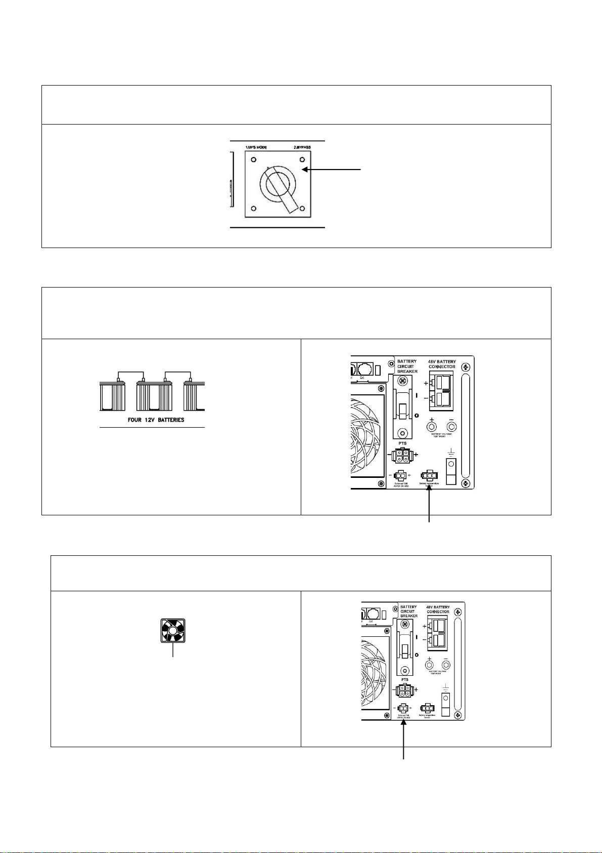
Verify the UPS MODE / BYPASS switch is in BYPASS.
Attach optional Battery Temperature Sensor to the middle battery. Plug the connector on
the other end into the TRTC-2002-N1.
Wrap a tie around the strain relief loop and the
battery temperature sensor to prevent the
connector from disconnecting during an
earthquake or other severe vibrations.
Attach External Cabinet Fan into the respective connector on the TRTC-2002-N1.
Wrap a tie around the strain relief loop and
the fan to prevent the connector from
disconnecting during an earthquake or other
severe vibrations.
21
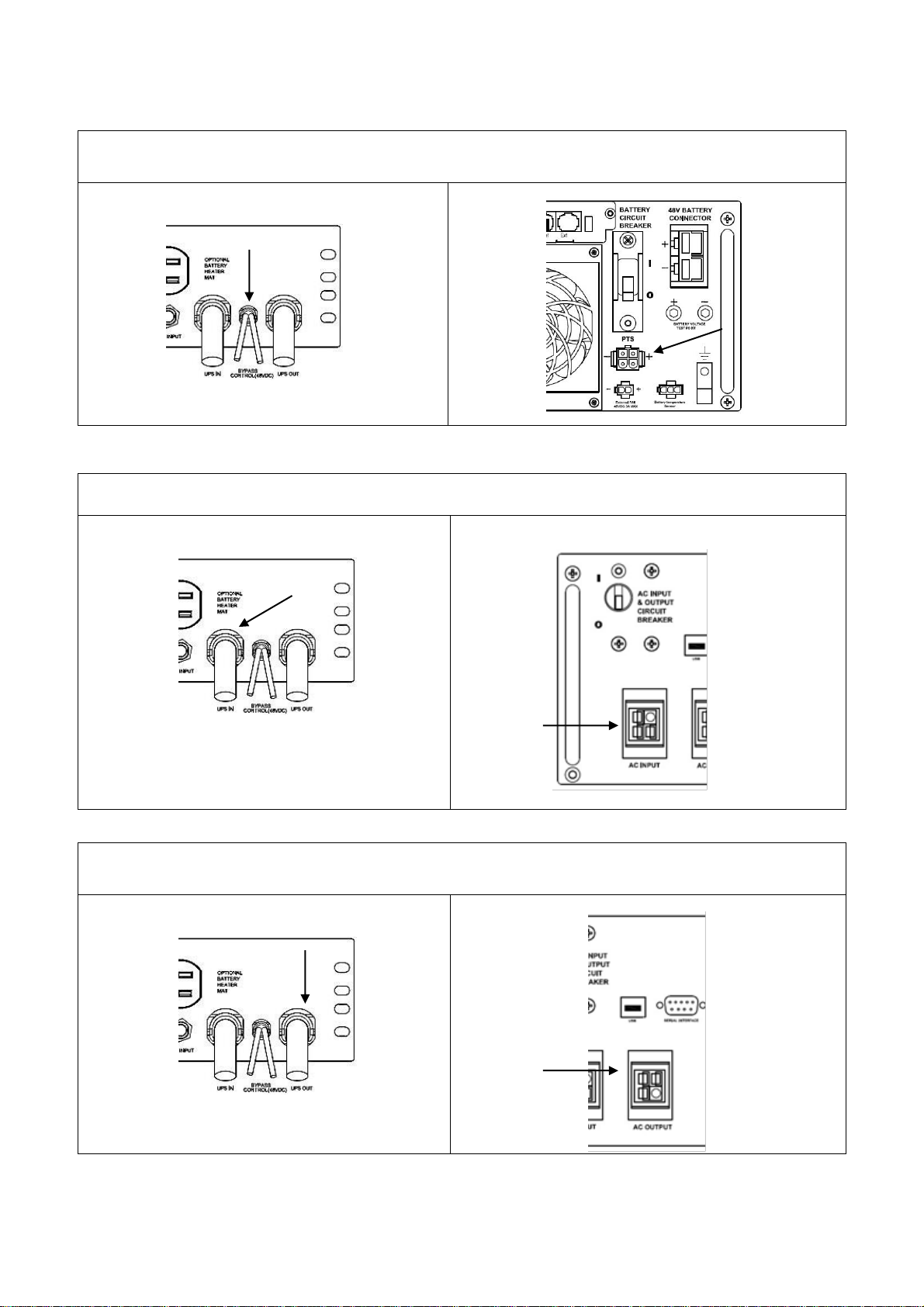
Connect the BYPASS CONTROL wires to the PTS connector into the TRTC-2002-N1.
Connect the PTS UPS IN to the UPS AC INPUT.
Attach PTS UPS OUT to the UPS AC OUTPUT.
22
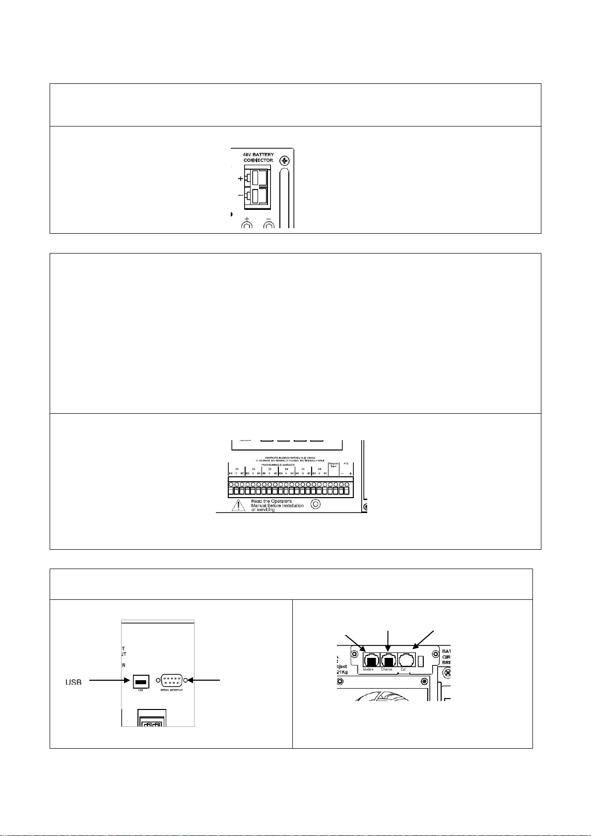
Connect the cable from the batteries to the 48V BATTERY CONNECTOR into the
TRTC-2002-N1.
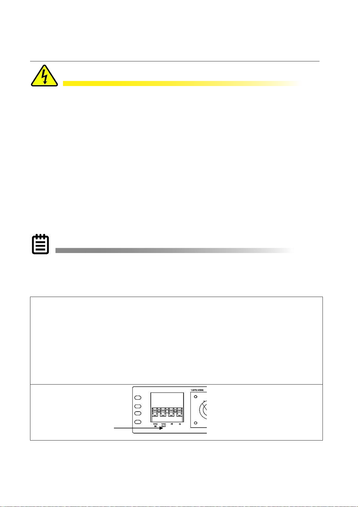
Each of the six contacts are of form C type, meaning Normally Open (NO), common (C) and
Normally Closed (NC) dry contact rated for 1A @ 240VAC. Each of these contacts can be
individually programmed to energize and stay latched for ON BATTERY, LOW BATTERY,
TIMER, ALARM, FAULT and many other conditions as described in subsequent chapters.
The ON BATTERY contact(s) are activated as soon as the unit is transferred to Battery
mode. LOW BATTERY contact(s) are activated only in the Battery mode, as soon as the
discharged battery reaches the lower value battery capacity as set by user and remains
latched as long as the system remains in Battery mode.
The TIMER contact(s) are activated only in the Battery mode after the user-programmed
time is attained, that can be set in 15 minute intervals from 15 minutes to 8 hours.
Torque status/self-test terminal block to a maximum of 4.4 lb.-in (0.5Nm).
Maximum wire size 14 AWG.
Connect the COMMUNICATION CABLES where appropriate.
SERIAL
MODEM
ETHERNET
23
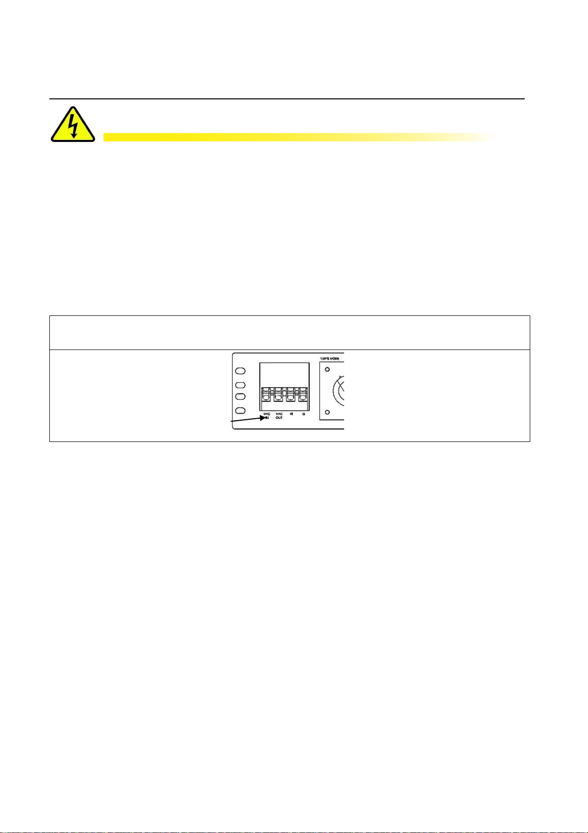
4.3 Connecting the Output or Signal Cabinet
1. Connect a black wire from the VAC Out at the PTS to the Input Hot terminal in the signal cabinet.
2. The wires from Ground and Neutral Bus Bars from the traffic cabinet are extended to PTS
Terminal Block.
3. OPEN the upstream breaker feeding utility power to the signal cabinet.
4. Disconnect the HOT wire (Black) connected between utility and traffic cabinet.
5. The cabinet side HOT wire is connected to “AC OUT” on the PTS.
6. The utility side HOT wire is connected to “VAC IN” on the PTS.
7. Torque the PTS terminal block to a maximum of 10.0 lb-in (1.1 Mm).
DANGER!
TIP:
24
If the installation is at an active intersection, have law enforcement begin directing
traffic before the power to signals is turned off.
If this is a new traffic signal installation with Utility AC power going directly to UPS,
make sure the upstream circuit breaker feeding the Utility Power is OFF before
beginning this step. If this is addition of a UPS to an existing traffic signal cabinet, DO
NOT terminate the power cable from the signal cabinet to the UPS at the signal cabinet
end until the final step after all other connections have been completed. This will
minimize the length of time the traffic signals must be off for final power connection.
There are many different ways that the Utility AC can be wired into the traffic signal
cabinet. The intent of this manual is only to explain proper connection of utility AC at
the UPS end of the cable. How the Utility AC is routed from the service entrance or
through the traffic signal cabinet (hereafter referred to as the “power source”) to the
UPS shall be determined by a licensed electrician in accordance with local electrical
codes.
The suggested method of wiring Utility AC to the UPS from the traffic signal cabinet is
to connect the UPS at the traffic cabinet after the main cabinet breaker and surge
suppressor so that the UPS is also protected by the cabinet surge suppressor.
4.4 Connecting the Utility Line Input Power
Connect the input HOT black wire from utility to “VAC IN” on PTS. Run wires from neutral
and ground bus bars of traffic cabinet to PTS neutral & ground terminal blocks.
DANGER!
25
If the installation is at an active intersection, have law enforcement begin directing
traffic before the power to signals is turned off.
Make sure the upstream circuit breaker for the power source is OFF before performing
this step. Make sure both the BATTERY CIRCUIT BREAKER on the unit is also off.
Make sure the upstream circuit breaker feeding the utility power is OFF before
beginning this step. Leave the NEUTRAL and GROUND wires connected from utility
to signal cabinet. Extend the NEUTRAL and GROUND wires from their corresponding
bus bars in the traffic cabinet to the terminal block on the PTS.

Verify that the AC Input &
Output as well as the
Battery Circuit Breaker on
the TRTC-2002-N1 are Off.
Place the Manual Bypass
Switch in the UPS
position.
Turn ON the upstream
Utility Input Circuit
Breaker.
Verify the load
has power.
Turn ON the AC Input &
Outout Circuit Breaker.
Turn ON the
Battery
Circuit
Breaker.
LCD display
shows
STANDBY.
In 30 seconds, The LCD display changes to "ON
LINE", the Green Output LED is Lit indicating
Input power to be within acceptable frequrncy
and voltage ranges and the output is powered
from Utility.
TIP:
26
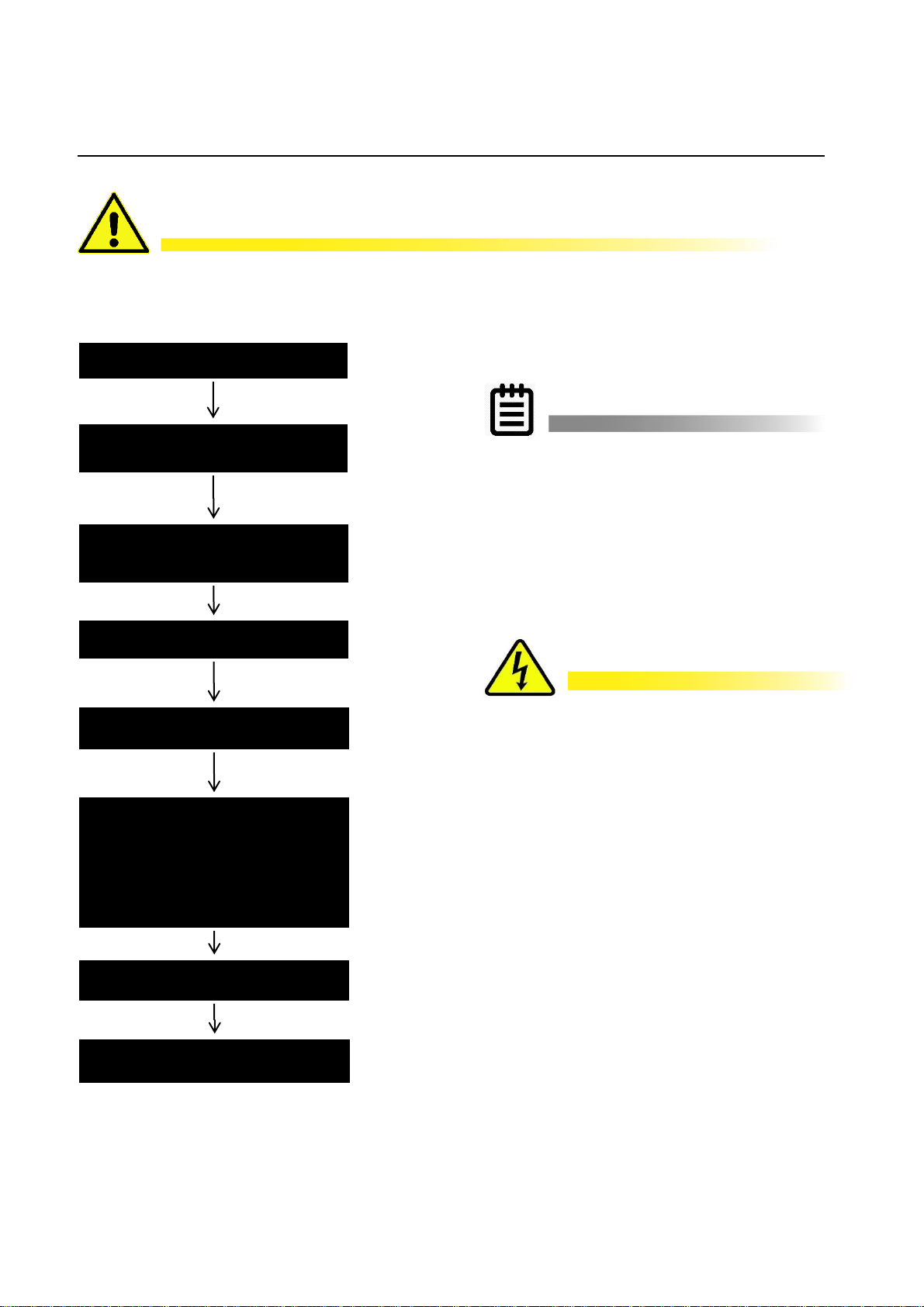
4.5 Starting Up the UPS
Purpose: Describes how to Start-up the system.
If the system does not perform as described below, see TRTC-2002-N1
Troubleshooting Section 9.2.
Step 1: Turn on the Utility Input Line Power
STARTUP PROCEDURE TIPS:
The UPS automatically starts up in STANBY mode.
After the AC line is qualified (default 30 seconds) the UPS switches to ON LINE mode
The PTS is fail safe in that the cabinet will always revert to utility power if there is ever
a failure of the UPS or batteries.
As an intersection safety measure, if there is no AC power and/or the AC breaker is
not ON, the UPS will stay in STANDBY and can only be placed ON BATTERY
manually to prevent accidentally leaving the intersection in operation on batter power
without restoring AC power.
Step 2: Turn on the UPS

Turn OFF the
upstream circuit
breaker.
The OUTPUT Green LED will
flash and the LCD displays ON
BATT, indicating that output
AC power is supplied from
battery power.
Observe the Red Alarm LED. If it is on or
flashes, follow the troubleshooting sequence
as below:
1. Investigate the Alarm/Fault.
2. Perform a self-test with the load(s)
connected.
3. If it passes the self-test, verify that that
loads are operating normally.
4. See the troubleshooting table in the
manual.
5. Contact Customer Service.
Turn ON the upstream circuit
breaker.
Within 30 seconds the PTS
switches back to line power.
The Green Output LED is lit
and the display shows
"ON LINE".
TIP:
ATTENTION!
27
4.6 Testing the UPS
Before turning off the AC power to the intersection as a final test, verify proper
installation and ability to go ON BATTERY by placing the MANUAL BYPASS SWITCH
to BYPASS. The unit should immediately go ON BATTERY. When the MANUAL
BYPASS SWITCH is returned to UPS, the unit should go back On Line after AC Qualify
time. Then to test the UPS further, perform the self-test feature via the CONTROL
submenu (see Section 5.7 Control).
When performing the test below, if for any reason the unit fails to go ON BATTERY,
immediately restore the AC power for the intersection at the upstream circuit breaker.
Place Manual Bypass Switch in
Bypass.
Turn OFF the Battery Circuit
Breaker.
Turn OFF the AC Input & Output
Circuit Breaker.
Unplug the battery connector.
Disconnect the AC input & Output
wires and insulate.
Disconnect, mark and insulate wires
at the Green Control Terminal Block,
the plug for Ext. Fan, the plug for
battery temperature sensor and
the RS232 or USB connector.
Remove and perform maintenance
on the TRTC-2002-N1.
Perform this procedure in the reverse
order to reinstall the unit.
ATTENTION!
IMPORTANT: Place the Manual
Bypass Switch in BYPASS before
doing any maintenance on the unit
or PTS to prevent accidentally losing
power to the traffic signals.
The AC input wires from PTS are
still HOT or Live. Insulate the bare
wires using wire nuts.
28
4.7 Shutting Down the UPS
Purpose: Describes how to shut down the system components for removal or maintenance.
Shutting down the TRTC-2002-N1 does not necessarily disconnect power to the loads.
ace Mnual Bypass Switch in Bypass.
 Loading...