

Marathon Power Track User Manual

Track Series
Line Interactive, True Sine Wave Output
Uninterruptible Power Supply
USER MANUAL


Introduction & Important Safety Instructions
Dear Customer,
Thank you for selecting a Marathon Power Uninterruptible Power Supply (UPS). You can rest assured
that you have purchased a product consistent with our reputation for quality and reliability. It will provide
you with years of protection against disruptive and costly power disturbances. As future needs arise, we
hope you will consider other products of ours.
Sincerely,
Marathon Power Inc.
2538 E. 54th Street
Huntington Park, CA 90037
Tel: 310-689-2328
Fax: 310-689-2329
_______________________________
Please take the time to read this manual!
It provides safety, installation and operating instructions that will allow you to derive the maximum
performance and service life from your UPS.
Please store this manual in a safe place!
It contains important instructions for the safe use of the UPS and for obtaining factory service should
you experience operational difficulties.
Please save or recycle the packaging materials!
They were designed to provide adequate protection from transport related damage. Since damage
sustained during transit is not covered under warranty, we recommend saving the material in case
the UPS needs to be returned for service or repair. Alternately, please recycle them.

IMPORTANT SAFETY INSTRUCTIONS
SAVE THESE INSTRUCTIONS
1. This Manual Contains Important Instructions that should be followed during Installation and
Maintenance of the UPS and Batteries.
2. The equipment can be operated by any individual. No previous experience is required.
3. CAUTION (UPS with Internal Batteries): Risk of electric shock - Hazardous live parts inside
this unit are energized from the battery supply even when the input AC power is disconnected.
4. CAUTION (No User Serviceable Parts): Risk of electric shock, do not remove cover. No user
serviceable parts inside. Refer servicing to qualified service personnel.
5. CAUTION (Non-isolated Batte ry Supply): Risk of electric shock, battery circuit is not isolated
from AC input; hazardous voltage may exist between battery terminals and ground. Test before
touching.
6. WARNING (Fuses): To reduce the risk of fire, replace only with the same type and rating of fuse.
7. WARNING: Intended for installation in a controlled environment. The maximum ambient
temperature is 40°C.
8. CAUTION: When replacing batteries, replace with the same type and number of batteries:
9. CA
UTION: Do not dispose of batteries in a fire, as they may explode.
10. CAUTION: Do not open or damage the battery, electrolyte may be released which is harmful to
the skin and eyes.
11. CAUTION: A battery can present a risk of electric shock and high short circuit current.
The following precautions should be taken when working with batteries:
a. Remove watches, rings and other jewelry or metal objects.
b. Use only tools with insulated handles.
c. Wear rubber gloves and boots.
d. Do not lay tools or metal parts on top of batteries.
e. Disconnect charging source prior to connecting or disconnecting battery terminals.
12. To reduce the risk of electric shock, disconnect the UPS from the AC input power supply
before installing a communication interface cable. Reconnect the power cord only after
communication interconnections have been made.
13. Battery replacement should be performed or supervised by personnel with knowledge of
batteries. Keep unauthorized personnel away from the batteries.
14. CAUTION: To reduce risk of fire, use only No. 26 AWG or larger telecommunication line cord.
15. CAUTION (For 700-2000VA Models Only): To reduce risk of fire, connect only to a circuit provided with 20 amperes maximum branch circuit over-current protection in accordance with the
National Electric Code, ANSI/NFPA 70”. An AC output disconnect shall be provided by others.
16. CAUTION (For 3000VA Models Only):
with 30 amperes maximum branch circuit over-current protection in accordance with the
National Electric Code, ANSI/NFPA 70”. An AC output disconnect shall be provided by others.
17. CAUTIO
type TW cable, trade size 1 in. conduit, 60°C, copper wire for input an output field wiring. For
3000VA models: Use No. 8 AWG type TW cable, trade size 1 in. conduit, 60°C, copper wire for
input and output field wiring. Use tightening torque of 40Nm to secure wiring to terminal block.
N (For Models with I/P Terminal Block): For 800 - 2000VA models: Use No. 10 AWG
To reduce risk of fire, connect only to a circuit provided

Table of Contents
Section Page
1. Overview . . . . . . . . . . . . . . . . . . . . . . . . . . . . . . . . . . . . . . . . . . . . . . . . . . . . . . . . . . . . . . . . . .1
2. Safety . . . . . . . . . . . . . . . . . . . . . . . . . . . . . . . . . . . . . . . . . . . . . . . . . . . . . . . . . . . . . . . . . . . . .1
3. Functionality . . . . . . . . . . . . . . . . . . . . . . . . . . . . . . . . . . . . . . . . . . . . . . . . . . . . . . . . . . . . . . . .2
4. Installation . . . . . . . . . . . . . . . . . . . . . . . . . . . . . . . . . . . . . . . . . . . . . . . . . . . . . . . . . . . . . . . . .8
5. Operation . . . . . . . . . . . . . . . . . . . . . . . . . . . . . . . . . . . . . . . . . . . . . . . . . . . . . . . . . . . . . . . . . .13
6. Alarms . . . . . . . . . . . . . . . . . . . . . . . . . . . . . . . . . . . . . . . . . . . . . . . . . . . . . . . . . . . . . . . . . . . 14
7. Software Options . . . . . . . . . . . . . . . . . . . . . . . . . . . . . . . . . . . . . . . . . . . . . . . . . . . . . . . . . . . .14
8. Care & Maintenance . . . . . . . . . . . . . . . . . . . . . . . . . . . . . . . . . . . . . . . . . . . . . . . . . . . . . . . . .15
9. Computer Interface Port . . . . . . . . . . . . . . . . . . . . . . . . . . . . . . . . . . . . . . . . . . . . . . . . . . . . . . 15
10. Battery Replacement . . . . . . . . . . . . . . . . . . . . . . . . . . . . . . . . . . . . . . . . . . . . . . . . . . . . . . . . .16
11. Storage . . . . . . . . . . . . . . . . . . . . . . . . . . . . . . . . . . . . . . . . . . . . . . . . . . . . . . . . . . . . . . . . . . 17
12. Fault Codes . . . . . . . . . . . . . . . . . . . . . . . . . . . . . . . . . . . . . . . . . . . . . . . . . . . . . . . . . . . . . . . 17
13. Troubleshooting . . . . . . . . . . . . . . . . . . . . . . . . . . . . . . . . . . . . . . . . . . . . . . . . . . . . . . . . . . . . .18
14. Specifications . . . . . . . . . . . . . . . . . . . . . . . . . . . . . . . . . . . . . . . . . . . . . . . . . . . . . . . . . . . . . .19
15. Product Warranties . . . . . . . . . . . . . . . . . . . . . . . . . . . . . . . . . . . . . . . . . . . . . . . . . . . . . . . . . . 23

1. Overview
Marathon Power's Track models are ideal for more critical applications where a true sine wave
output while in backup mode is required along with the efficiency of a line-interactive design. Tapchanging AVR (Automatic Voltage Regulation) provides mitigation of sags and swells without the
need to transfer to battery. Battery energy is conserved for more severe disturbances such as
interruptions and outages.
Tight voltage and frequency regulation along with fast transfer ensures the seamless transfer of
uninterrupted power to the load. Included is generic power monitoring & UPS control software.
They feature a unique energy saving “Sleep Mode” that reduces the cost of ownership and
“Cold Start” that allows the UPS to be used as a small emergency power source.
Using the UPS with the included software* and interconnecting cable allows intelligent control of the
system when linked to a host computer. (Some operating systems require other optional software)
There are dry contacts or solid state signalling via a standard RS-232 port that allows for remote
notification of basic functions such as Power Normal, Backup Mode, & Low Battery states.
* Software is presently available for PC operating systems only.
2. Safety
WARNINGS AND CAUTIONS!
!
Please be aware of, and observe the following:
• To reduce the risk of electric shock, disconnect the UPS from the main AC supply before installing any
interface cables. Reconnect the power cord only after the signaling interconnections have been made.
• The internal energy source (the battery) cannot be de-energized by the user. The output may be
energized when the unit is not connected to the AC supply.
• The correct way to de-energize the UPS properly in an emergency is to move the I/O switch to the
OFF position and disconnect the power cord from the main supply.
• Even when the unit is disconnected, risk of electric shock from parts energized by the battery inside unit
still exists. To avoid this, the battery supply should be disconnected at positive and negative terminals.
• The outlet sockets should be installed near the equipment and easily accessible.
• Do not dispose of batteries in a fire as they may explode. Please contact tech support for proper
disposal instructions.
• Do not open or attempt to dismantle the battery, as electrolyte that is harmful to the skin and eyes
may be released.
• A battery can present a risk of electric shock and high short circuit current. The following precautions
should be taken when working with them:
- Remove watches, rings and other jewelry or metal objects.
- Use tools with insulated handles.
• To reduce risk of fire, replace only with same type and rating of fuse.
• To reduce the risk of fire or electric shock, install the UPS in a temperature and humidity controlled
indoor area free of conductive contaminants.
1
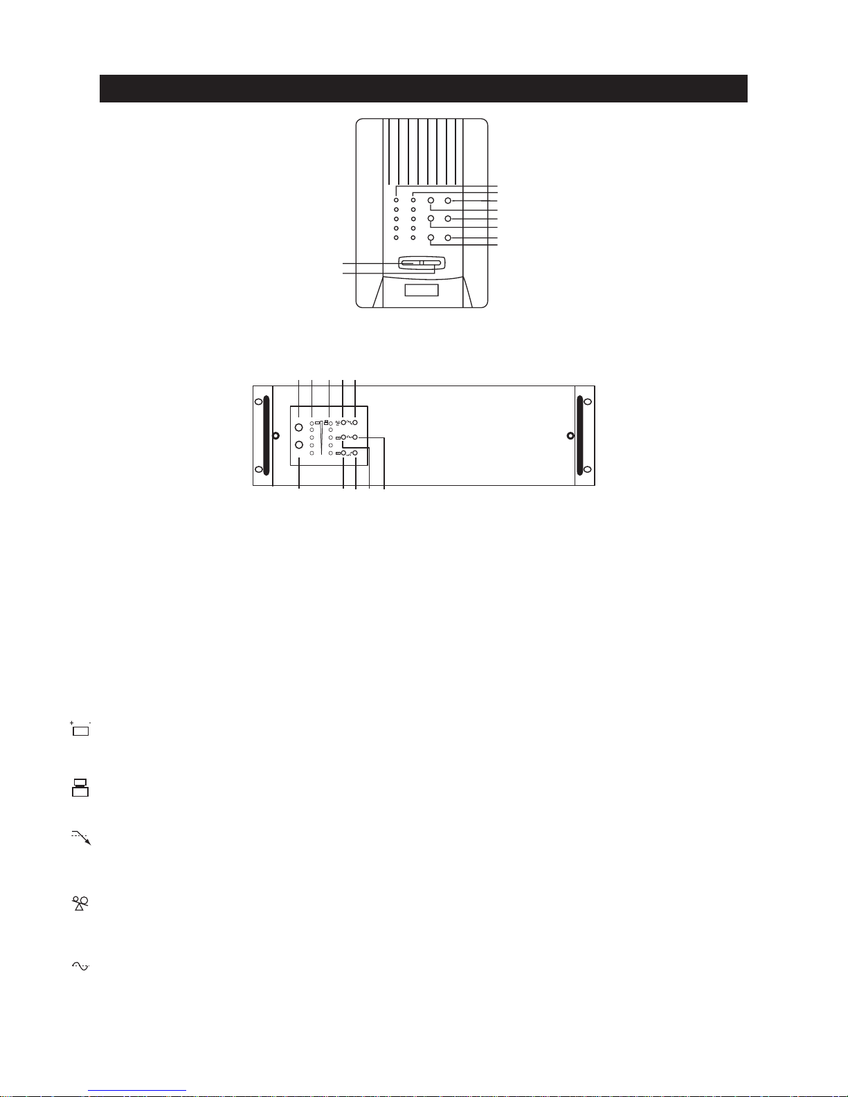
3. Functionality – Front Views
3.1
3.2
LED TOWER MODELS
3.3
3.4
3.5
3.6
3.7
3.8
3.9
3.10
(not to scale)
3.1
ON/TEST
OFF
3.2 3.10 3.9 3.8 3.7
3.53.63.43.3
+-
--
--
LED RACK MOUNT MODELS
For units with an LED display
3.1 “ ON/TEST” Button
Once connected, pressing this button turns the UPS on and powers the loads. Depressing it for 1 (one)
second activates the UPS's self-test function (while in normal power mode) or silences the alarm
(while in backup mode).
3.2 “ OFF” Button
Pressing this button turns OFF the UPS and its connected loads.
3.3 “ POWER” Bar Graph (BATTERY CHARGE/LINE VOLTAGE)
This display shows the present battery charge as a percentage of battery capacity. It also displays
utility line voltage.
3.4 “ LOAD” Bar Graph
This LED display shows the power being drawn by the load.
3.5 “ BUCK (AVR)” Indicator (YELLOW LED)
This LED illuminates when the UPS is correcting a voltage swell or over-voltage condition. The load
receives normal power.
3.6 “ OVERLOAD” Indicator (RED LED)
This LED illuminates when the load(s) connected to the UPS exceeds the UPS's capacity (power rating).
See Section 6.
3.7 “ LINE NORMAL” Indicator (GREEN LED)
This LED will illuminate when the AC line input voltage is normal.
2
3.8 “ BACKUP” Indicator (GREEN LED)
This LED illuminates when the UPS is supplying battery power to the loads.
3.9 “ BOOST (AVR)” Indicator (YELLOW LED)
This LED illuminates when the UPS is correcting a voltage sag or undervoltage condition. The load
receives normal power.
3.10 “ REPLACE BATTERY” Indicator (RED LED)
This LED illuminates when the UPS's battery is no longer useful and must be replaced. See section 10.
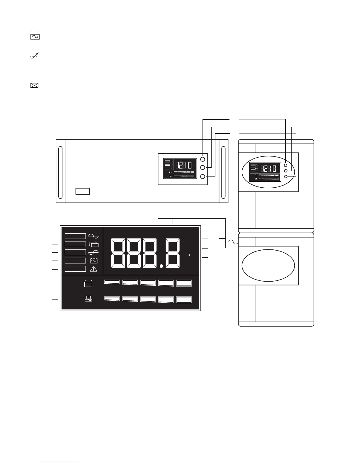
3.11
(not to scale)
3.12
3.13
LCD RACK MOUNT MODELS
3.14
3.15
3.16
3.17
3.18
3.19
3.20
LINE
BY PASS
INV
INV
BACKUP
FAU LT
BATT
0 % 20 % 40 % 60 % 80 % 100 %
LOAD
0 % 20 % 40 % 60 % 80 % 100 %
LCD DISPLAY DETAIL
LINE
BY PASS
INV
BACKUP
FAULT
BATT
LOAD
I/P O/P
INV
0 % 20 % 40 % 60 % 80 % 100 %
0 % 20 % 40 % 60 % 80 % 100 %
I/P O/P
Vac
Hz
Vac
ON
Hz
C
OFF
SELECT
LINE
BY PASS
INV
BACKUP
FAULT
BATT
LOAD
INV
0 % 20 % 40 % 60 % 80 % 100 %
0 % 20 % 40 % 60 % 80 % 100 %
I/P O/P
Vac
Hz
ON
C
OFF
SELECT
3.21
3.22
C
3.23
For units with an LCD display
3.11 “ ON/TEST” Button
Once connected, pressing this button turns the UPS on and powers the loads. It also activates the
UPS's self-test and utility line voltage displays.
3.12 “ OFF” Button
Pressing this button turns OFF the UPS and its connected loads.
3.13 “ SELECT” Button
Depressing and holding the select button cycles through various LCD display modes. Modes include:
Input Voltage, Output Voltage, Input Frequency, Output Frequency, Internal Temperature and Load (%).
LCD TOWER MODELS
3

3.14 LINE:
Indicates normal operation from AC line.
3.15 BYPASS:
Indicates the UPS is in bypass (standby) mode. Normal AC power supplies the load under this
condition. When there is a power disturbance, the unit will transfer to backup mode.
3.16 INV:
This indicates that the inverter, and therefore the unit, is functioning properly.
(The opposite of BYPASS mode.)
3.17 BACKUP:
Indicates unit is operating in backup mode during a power disturbance.
3.18 FAULT:
Indicates an internal electronic fault.
3.19 BATTERY LEVEL BAR GRAPH:
This graph shows the charge/energy level of the battery in 20% increments.
3.20 LOAD LEVEL BAR GRAPH:
This graph shows how much of the units available capacity is being utilized in 20% increments.
3.21 INPUT (I/P) OR OUTPUT (O/P) VOLTAGE (Vac):
Pressing the SELECT button untill I/P and Vac are both lit will display the input voltage to the unit
on the display. Likewise, you may press SELECT again to show O/P and Vac to indicate the units
output voltage.
3.22 INPUT (I/P) OR OUTPUT (O/P) FREQUENCY (Hz):
Pressing the SELECT button untill I/P and Hz are both lit will display the input frequency to the
unit on the display. Likewise, you may press SELECT again to show O/P and Hz to indicate the
units output frequency.
3.23 oC (Celsius):
With this indicator lit the unit will display the internal temperature of the unit in degrees celsius.
4
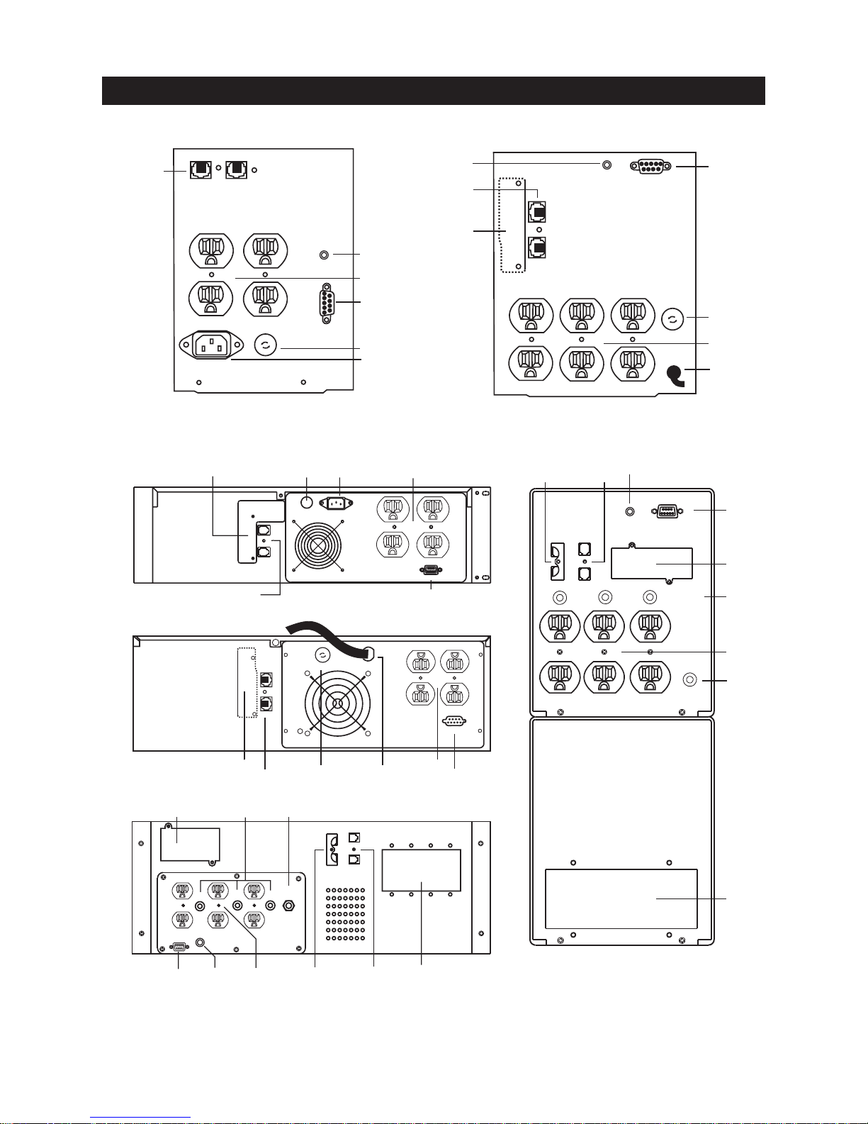
3. Functionality – Rear Views
3.24
IN
INPUT
STANDARD 600VA / 1000VA TOWER MODELS
STANDARD 600VA RM MODEL
OUT
OUTPUT
3.24
FUSE
U
F
E
S
U
3.30
3.24
SITE
WIRING
FAULT
REMOTE
PORT
(not to scale)
3.31
3.25/3.33
SITE
FIRING
FAULT
3.30
3.26
REMOTE
PORT
E
S
F
U
S
E
F
3.31
3.29
3.28
STANDARD 1500VA / 2000VA / 3000VA & EXTENDED RUN-TIME 1000VA TOWER MODELS
3.283.29
FUSE
INPUT
OUT
IN
3.263.25
OUTPUT
REMOTE
3.31
OUTPUT
3.33
OUTPUT OUTPUT OUTPUT
CIRCUIT BREAKER CIRCUIT BREAKER CIRCUIT BREAKER
3.24
IN
OUT
3.30
SITE
WIRING
FAULT
FUSE
U
F
E
S
U
F
INPUT
REMOTE
PORT
E
S
F
U
S
3.29
E
3.26
3.28
3.31
3.25
3.27
STD & EXT RUN-TIME RM MODELS
3.25 3.293.27
EXTENDED RUN-TIME RACK-MOUNT 3000VA MODEL EXTENDED RUN-TIME 1500VA / 2000VA / 3000VA TOWER MODELS
REMOTE
CIRCUIT
BREAKER
PORT
3.33
CIRCUIT
BREAKER
3.30 3.323.243.333.31 3.26
3.24
CIRCUIT
BREAKER
E
S
U
F
F
U
S
E
E
S
U
F
OUT
IN
FUSE INPUT
3.283.29
OUT
IN
CIRCUIT
BREAKER
OUTPUT
3.26
OUTPUT
REMOTE
3.31
INPUT
CIRCUIT BREAKER
3.26
3.28 / 3.29
3.32
5
 Loading...