

Marathon Power Athlon User Manual

Athlon Series
True On Line, Double Conversion
Uninterruptible Power Supply
USER MANUAL


Introduction & Important Safety Instructions
Dear Customer,
Thank you for selecting a Marathon Power Uninterruptible Power Supply (UPS). You can rest assured
that you have purchased a product consistent with our reputation for quality and reliability. It will provide
you with years of protection against disruptive and costly powerdisturbances. As future needs arise, we
hope you will consider other products of ours.
Sincerely,
Marathon Power Inc.
103 W. Martin Luther King Blvd.
Los Angeles, CA 90037
Tel: 310-689-2328
Fax: 310-689-2329
_______________________________
Please take the time to read this manual!
It provides safety, installation and operating instructions that will allow you to derive the maximum
performance and service life from your UPS.
Please store this manual in a safe place!
It contains important instructions for the safe use of the UPS and for obtaining factory service
should you experience operational difficulties.
Please save or recycle the packaging materials!
They were designed to provide adequate protection from transport related damage. Since damage
sustained during transit is not covered under warranty, we recommend saving the material in case
the UPS needs to be returned for service or repair. Alternately, please recycle them.

Table of Contents
Section Page
1. Overview . . . . . . . . . . . . . . . . . . . . . . . . . . . . . . . . . . . . . . . . . . . . . . . . . . . . . . . . . . . . . . . . . .1
2. Safety & EMC . . . . . . . . . . . . . . . . . . . . . . . . . . . . . . . . . . . . . . . . . . . . . . . . . . . . . . . . . . . . . . .2
3. Functionality . . . . . . . . . . . . . . . . . . . . . . . . . . . . . . . . . . . . . . . . . . . . . . . . . . . . . . . . . . . . . . . .4
4. Installation . . . . . . . . . . . . . . . . . . . . . . . . . . . . . . . . . . . . . . . . . . . . . . . . . . . . . . . . . . . . . . . .7
5. Operation . . . . . . . . . . . . . . . . . . . . . . . . . . . . . . . . . . . . . . . . . . . . . . . . . . . . . . . . . . . . . . . . .12
6. Alarms . . . . . . . . . . . . . . . . . . . . . . . . . . . . . . . . . . . . . . . . . . . . . . . . . . . . . . . . . . . . . . . . . . . .13
7. Software Options . . . . . . . . . . . . . . . . . . . . . . . . . . . . . . . . . . . . . . . . . . . . . . . . . . . . . . . . . . . .13
8. Care & Maintenance . . . . . . . . . . . . . . . . . . . . . . . . . . . . . . . . . . . . . . . . . . . . . . . . . . . . . . . . .14
9. Computer Interface Port . . . . . . . . . . . . . . . . . . . . . . . . . . . . . . . . . . . . . . . . . . . . . . . . . . . . . .14
10. Battery Replacement . . . . . . . . . . . . . . . . . . . . . . . . . . . . . . . . . . . . . . . . . . . . . . . . . . . . . . . . .15
11. Storage . . . . . . . . . . . . . . . . . . . . . . . . . . . . . . . . . . . . . . . . . . . . . . . . . . . . . . . . . . . . . . . . . .16
12. External Battery Packs . . . . . . . . . . . . . . . . . . . . . . . . . . . . . . . . . . . . . . . . . . . . . . . . . . . . . . .16
13. Troubleshooting . . . . . . . . . . . . . . . . . . . . . . . . . . . . . . . . . . . . . . . . . . . . . . . . . . . . . . . . . . . .17
14. Specifications . . . . . . . . . . . . . . . . . . . . . . . . . . . . . . . . . . . . . . . . . . . . . . . . . . . . . . . . . . . . .18
15. Product Warranties . . . . . . . . . . . . . . . . . . . . . . . . . . . . . . . . . . . . . . . . . . . . . . . . . . . . . . . . .22
1. Overview
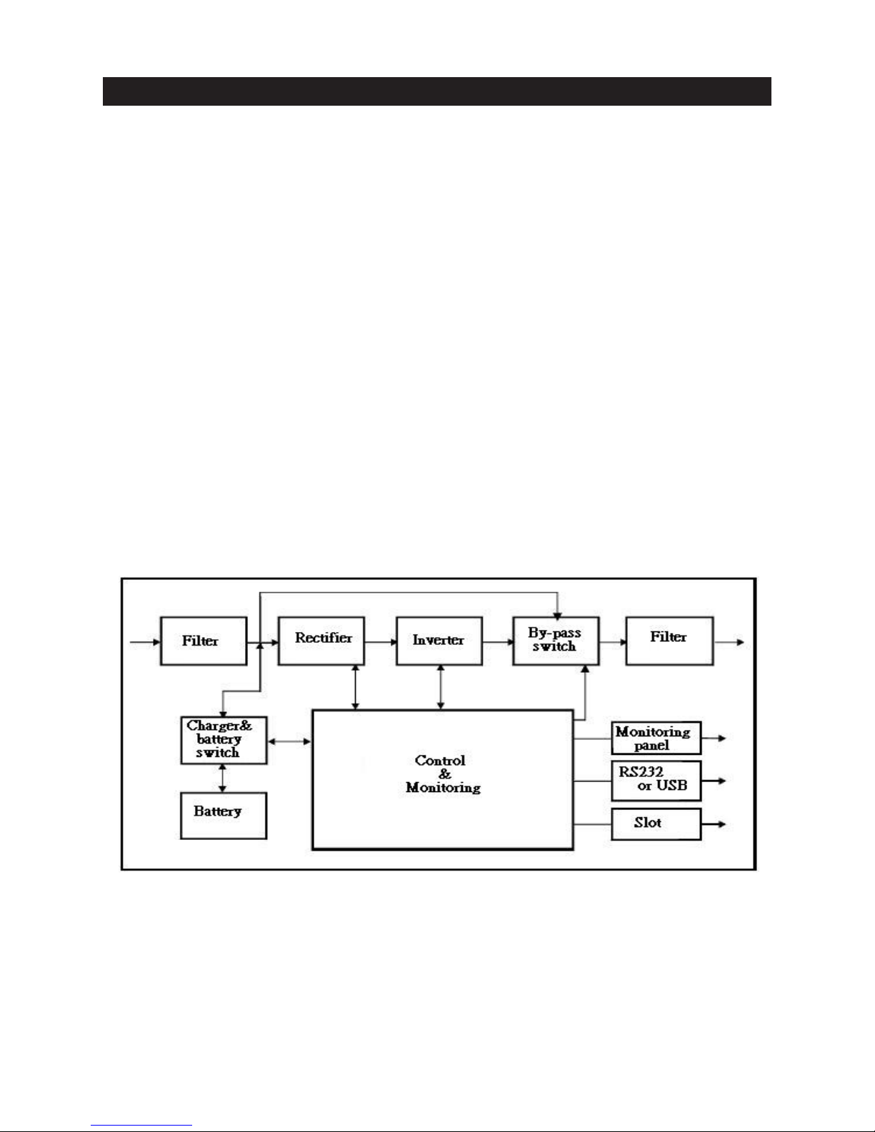
For use in the most critical applications, these models are true on-line, double conversion designs
that provide a continuous, true sine-wave output with less than 3% total harmonic distortion
(THD). They allow for a wide input voltage range of +-27% and also feature power factor correction
and dual microprocessors for control of all functions.
Unique features include a ‘cold-start’ function that allows the user to power up the load(s) directly
from the UPS without the presence of utility power, a multi-function LCD display and cooling fans
that vary their speed relative to load size.
Independent input and output fuses and circuit breakers protect against overload and shortcircuits and advanced battery management extends battery life by up to 50%. 2000VA and 3000VA,
120V models also come with hard-wire terminal blocks for permanent installation.
Using the UPS with the included software and interconnecting cable allows intelligent control
of the system when linked to a host computer. (Some operating systems may require the use
of other optional software). In addition to the RS-232 function of the communication port, solid
state signalling and remote control of basic UPS functions is available.
When an overload or malfunction occurs, the UPS automatically and seamlessly transfers to bypass
mode and continues to supply the load with utility power. Upon removal of the fault condition, the
unit automatically transfers back to inverter mode once the unit has been restarted.
Block Diagram
1

EMC Statements
FCC Part 15
NOTICE: Pursuant to section 15 of the FCC rules, this product has been tested and thereby complies
with the conditions of a Class B (700-2000VA) and Class A (3000VA) digital device, which have been
established for offering sufficient protection against dangerous interference for installation in a
residential area. Installation and use of the equipment should comply with the instructions provided in
order to avoid such interference due to the amount of radio frequency energy that is radiated and
generated by the equipment. In spite of this, we cannot assure that a certain amount of interference may
not occur in some installations. If, by turning on and off, it can be deduced that your radio or television
reception is found to be influenced by harmful interference from the equipment, it is recommended that
one of the following preventive measures be used:
1. Place the receiving antenna in a separate location or orientation.
2. Ensure a greater distance is achieved between the receiver and the equipment.
3. Ensure that your equipment is connected to an outlet on a separate circuit than the receiver.
4. Contact a technician experienced with radio and TV or call tech support for further assistance.
ICES-003
This Class B Interference Causing Equipment meets all requirements of the Canadian Interference
Causing Equipment Regulations ICES–003. Cet appareil numérique de la classe B respecte toutes les
exigences du Reglement sur le matériel brouilleur du Canada.
Declaration of Conformity Request
Units labeled with a CE mark comply with the following standards and directives:
1. Harmonic Standards: EN 50091-1-1
2. EU Directives: 73/23/EEC, Council Directive on equipment designed for use within certain voltage
limits.
and EN 50091-2
93/68/EEC, Amending Directive 73/23/EEC
89/336/EEC, Council Directive relating to electromagnetic compatibility
92/31/EEC, Amending Directive 89/336/EEC relating to EMC
The EC Declaration of Conformity is available upon request for products with a CE mark.
2

IMPORTANT SAFETY INSTRUCTIONS
SAVE THESE INSTRUCTIONS
1. This Manual Contains Important Instructions that should be followed during Installation and
Maintenance of the UPS and Batteries.
2. The equipment can be operated by any individual. No previous experience is required.
3. CAUTION (UPS with Internal Batteries): Risk of electric shock - Hazardous live parts inside
this unit are energized from the battery supply even when the input AC power is disconnected.
Refer to top, rear and/or underside of the unit for cautionary markings.
4. CAUTION (No User Serviceable Parts): Risk of electric shock, do not remove cover. No user
serviceable parts inside. Refer servicing to qualified service personnel.
5. CAUTION (Non-isolated Battery Supply): Risk of electric shock, battery circuit is not isolated
from AC input; hazardous voltage may exist between battery terminals and ground. Test before
touching. Do not disconnect battery connector/s under load.
6. WARNING (Fuses): To reduce the risk of fire, replace only with the same type and rating of fuse.
7. CAUTION (Live Heat Sink): Risk of electric shock - heatsink is live. Disconnect unit prior to servicing.
8. WARNING (Controlled Environment): Intended for installation in a controlled environment.
The maximum ambient temperature is
9. CAUTION: When replacing batteries, replace with the same type and number of batteries:
One Sealed lead acid battery, rated 12 V, 8.5 Ah max. Do not touch uninsulted battery terminals
10. ATTENTION (Electric Shock Hazard): Even when the unit is disconnected from the AC supply,
hazardous voltage may still exist via the battery supply. The battery supply should be disconnected
at the positive and negative termianls when the UPS needs to be serviced or the batteries replaced.
77°F / 25°C.
11. CAUTION: Do not dispose of batteries in a fire, as they may explode.
12. CAUTION: Do not open or damage the battery, electrolyte may be released which is harmful to
the skin and eyes.
13. CAUTION: A battery can present a risk of electric shock and high short circuit current.
The following precautions should be taken when working with batteries:
a. Remove watches, rings and other jewelry or metal objects.
b. Use only tools with insulated handles.
c. Wear rubber gloves and boots.
d. Do not lay tools or metal parts on top of batteries.
e. Disconnect charging source prior to connecting or disconnecting battery terminals.
14. To reduce the risk of electric shock, disconnect the UPS from the AC input power supply
before installing a communication interface cable. Reconnect the power cord only after
communication interconnections have been made.
15. Battery replacement should be performed or supervised by personnel with knowledge of
batteries. Keep unauthorized personnel away from the batteries.
16. CAUTION: To reduce risk of fire, use only No. 26 AWG or larger telecommunication line cord.
17. CAUTION (High Leakage Current - Ground Connection Essential): The total leakage current
for the UPS and any connected equipment shall not exceed 3.5 mA.
18. CAUTION (Size of Branch Circuit Over-current Protection): To reduce risk of fire, connect only
to a circuit capable of 35 amperes (2000VA models) and 50 amperes (3000VA models) maximum
branch circuit over-current protection in accordance with National Electric Code, ANSI/NFPA 70.
19. CAUTION (For Models with I/P Terminal Block): For 800 - 1500VA models: Use No. 10 AWG
type TW cable, trade size 3/4 in. conduit, 60°C, copper wire for input an output field wiring. For
2000/3000VA models: Use No. 8 AWG type TW cable, trade size 3/4 in. conduit, 60°C, copper
wire for input/output field wiring. Use tightening torque of 29 ft.-lbs./40Nm to secure wiring to block.
3
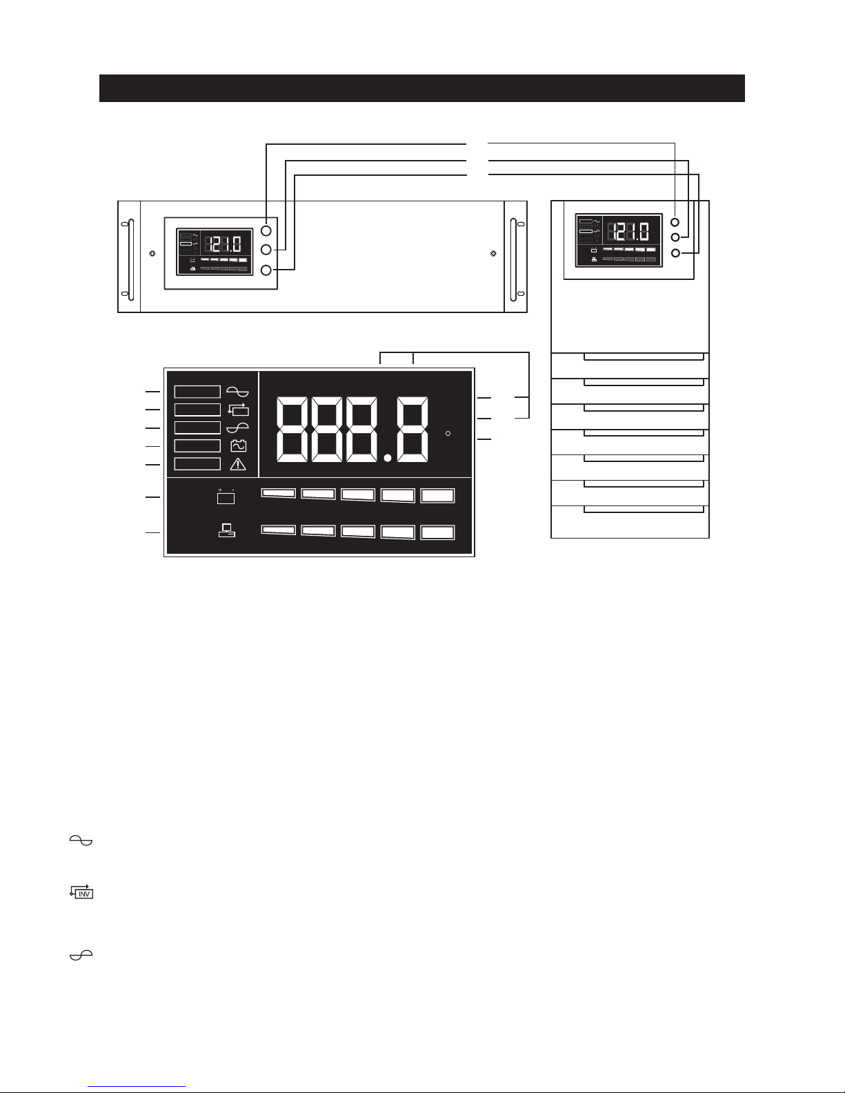
3. Functionality – Front Views
(not to scale)
INV
0 % 20 % 40 % 60 % 80 % 100 %
0 % 20 % 40 % 60 % 80 % 100 %
I/P O/P
Vac
Hz
C
LINE
BY PASS
INV
BACKUP
FAULT
BATT
LOAD
RACK-MOUNT MODELS
3.04
3.05
3.06
3.07
3.08
3.09
3.10
LINE
BY PASS
INV
BACKUP
FAU LT
BATT
LOAD
INV
LCD DISPLAY DETAIL
ON
OFF
SELECT
I/P O/P
Vac
Hz
0 % 20 % 40 % 60 % 80 % 100 %
0 % 20 % 40 % 60 % 80 % 100 %
3.01
3.02
3.03
LINE
BY PASS
INV
BACKUP
FAULT
BATT
LOAD
I/P O/P
INV
0 % 20 % 40 % 60 % 80 % 100 %
0 % 20 % 40 % 60 % 80 % 100 %
Vac
Hz
C
ON
OFF
SELECT
3.11
3.12
C
3.13
TOWER MODELS
3.01 “ON/TEST/SILENCE” Button
Once connected, pressing this button turns the UPS on and powers the loads. Depressing it for 1
second activates the UPS's self-test function (while in normal power mode) or silences the alarm
(while in back-up mode)
3.02 “OFF” Button
Pressing this button turns OFF the UPS and its connected loads.
3.03 “SELECT” Button
Depressing and holding the select button cycles through various LCD display modes. Modes include:
Input Voltage, Output Voltage, Input Frequency, Output Frequency and the Internal Temperature of
the UPS.
3.04 LINE:
Indicates normal operation from AC line.
3.05 BYPASS:
Indicates the UPS is in bypass mode due to a fault or manual bypass 'force' selection (See section 5).
Normal AC power will supply the load under this condition but the backup function will not operate.
3.06 INV:
This indicates that the inverter, and therefore the unit, is functioning properly.
(The opposite of BYPASS mode).
4

3.07 BACKUP:
Indicates unit is operating in backup mode during a power disturbance or loss of power.
3.08 FAULT:
Indicates an internal electronic fault.
3.09 BATTERY LEVEL BAR GRAPH:
This graph shows the charge/energy level of the battery in 20% increments.
3.10 LOAD LEVEL BAR GRAPH:
This graph shows how much of the units available capacity is being utilized in 20% increments.
3.11 INPUT (I/P) OR OUTPUT (O/P) VOLTAGE (Vac):
Pressing the SELECT button untill I/P and Vac are both lit will display the input voltage to the unit
on the display. Likewise, you may press SELECT again to show O/P and Vac to indicate the units
output voltage.
3.12 INPUT (I/P) OR OUTPUT (O/P) FREQUENCY (Hz):
Pressing the SELECT button untill I/P and Hz are both lit will display the input frequency to the
unit on the display. Likewise, you may press SELECT again to show O/P and Hz to indicate the
units output frequency.
3.13oC (Celsius):
With this indicator lit the unit will display the internal temperature of the unit in degrees celsius.
3. Functionality – Rear Views
5
 Loading...