

Page 1
QUICK START GUIDE
MaxiThermal
8-Channel WiFi
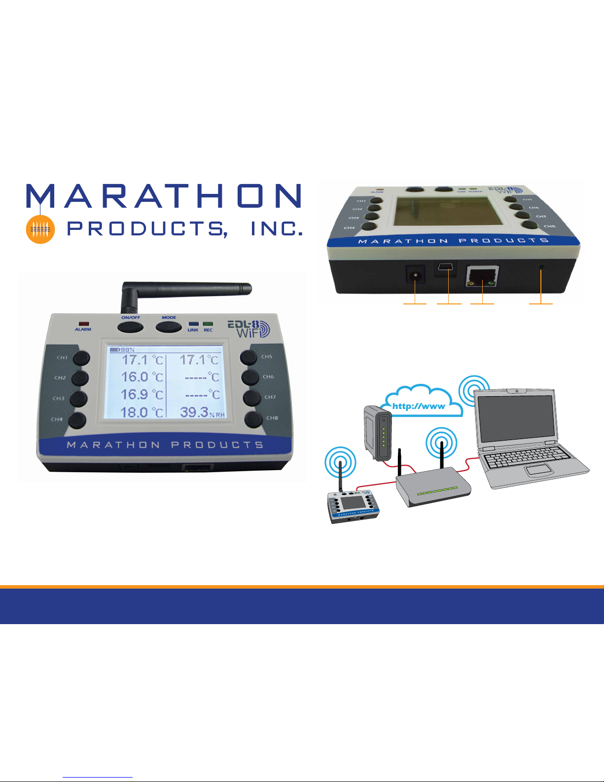
The 8 Channel WiFi logger can connect to your network by
either 802.11g WiFi or by standard 10/100 network cable.
DC Jack USB Port LAN Port Reset
Button
Page 2
Programming the 8-Channel WiFi logger to
connect to a WiFi Network.
STEP 1:
Install MaxiThermal WiFi software on your PC using the Autorun.exe file.
The installation should include automatic installation of the USB Socket Utility.
Connect the 8-Channel WiFi logger to your PC with
the USB cable.
PC CONNECTION
(WLAN)
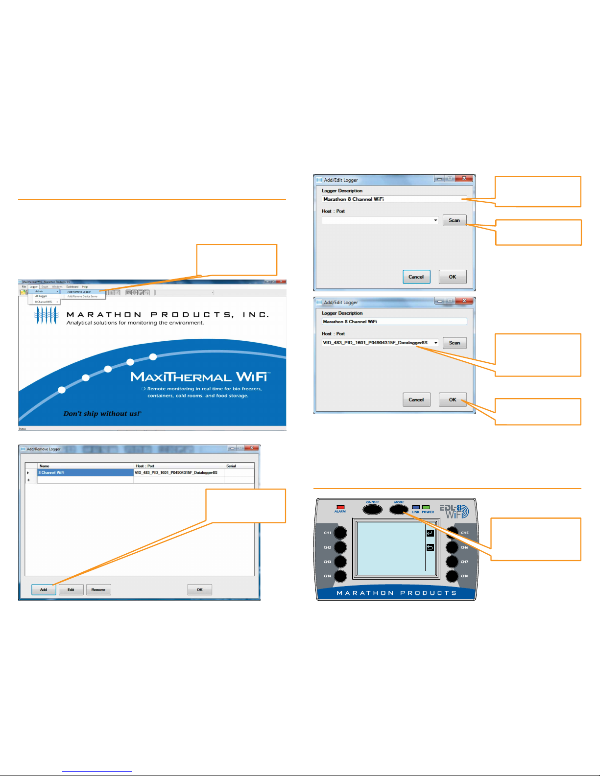
In the Menu Bar click
Logger / Admin /
Add/Remove Logger
For a new logger
click Add and a blank
window will open.
This will display the logger’s USB connection
information in the
window.
Click OK to close the
windows.
Click Scan to search for
the IP address.
Enter a name for the
new logger connected
by USB.
Disconnect the USB cable from the logger.
STEP 2:
On the 8-Channel
Logger push the MODE
button multiple times
until WLAN is displayed.
Page 3
PC LINK (WLAN)
WLAN: OFF
PC LINK (WLAN)
WLAN: ON
Connecting...
DGS2
PC LINK (WLAN)
WLAN: ON
IP Address:
192.168.1.58
DGS2
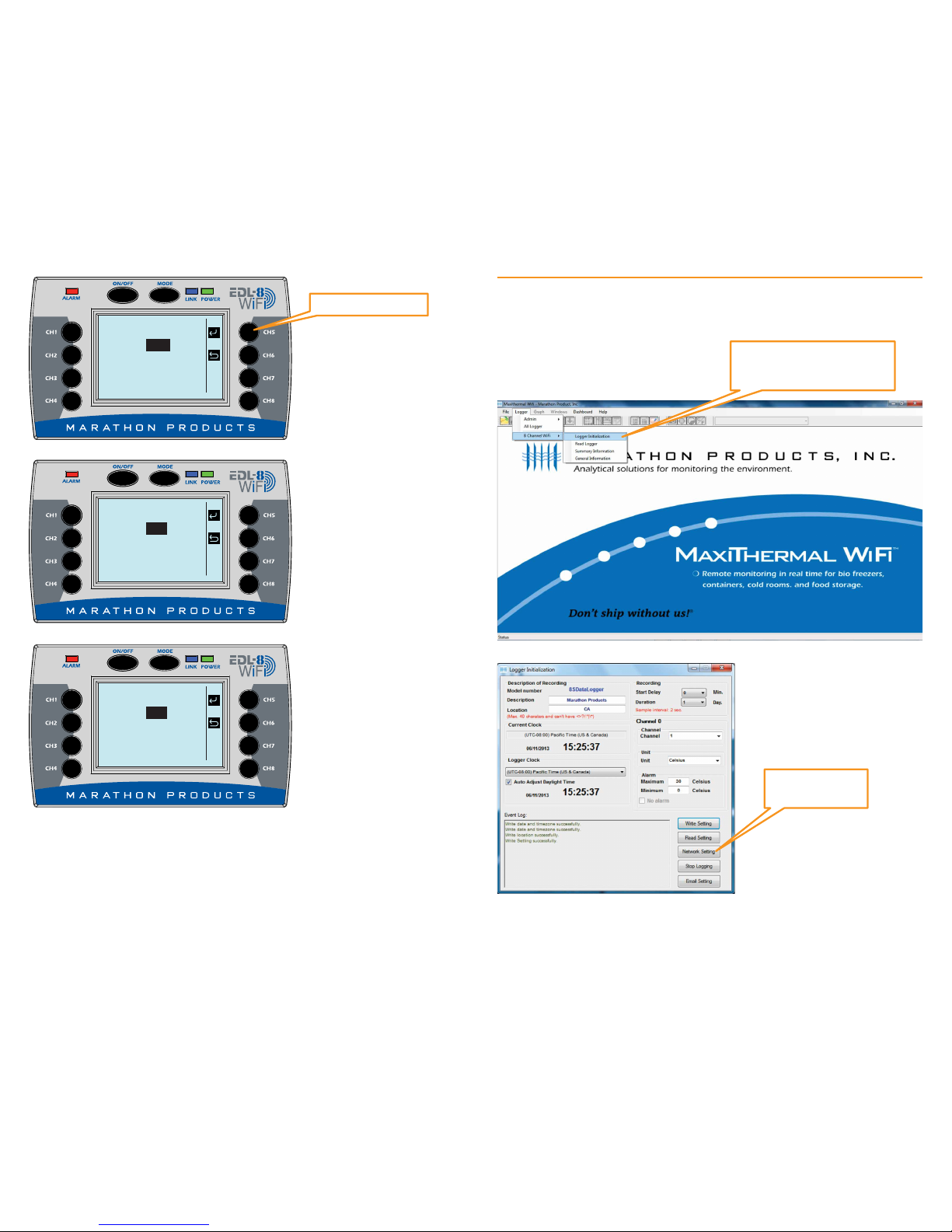
STEP 3:
Now that the logger has been assigned an IP address, you need to set up the WiFi
connection in the software so it can communicate with the logger.
Reconnect the USB cable to the logger.
Click on Network
Setting.
On the Menu Bar select
Logger / 8 Channel WiFi /
Logger Initialization
Push CH 5 to select.
Push CH 5 to turn ON WLAN
connection.
The logger will search for a
WiFi network to connect to.
When the logger connects to
the WiFi network it will display its IP address.
Make a note of the IP address
assigned by your network’s
DHCP server.
_____ • ____ • ____ • _____
Page 4

Enter your WiFi network’s
SSID name
Select WPA2 for Security
Type (If your network uses
a different security type
select that type).
Enter your WiFi network’s
Password.
Click Setting WiFi to write
the settings to the logger.
STEP 4:
For a new logger
click Add and a blank
window will open.
In the Menu Bar click
Logger / Admin /
Add/Remove Logger
A window will open which will list the USB logger name you entered earlier.
Here you will need to add the new WiFi logger defined in the previous step.
Disconnect the USB cable from the logger.
Page 5

Click the “Drop-Down”
arrow to see the IP
address of logger. Click
on the IP address.
This will display the logger
information in the window.
The logger should be connected to the WiFi network and ready for use.
Click Scan to search for
the IP address.
Enter a name for the
new logger connected
by WiFi.
Click OK to close the
windows.
Software Highlights
On the Menu Bar select Logger / 8
Channel WiFi / Logger Initialization
This will open a new window to program the logger’s 8 channels.
1. In the upper left Description of Recording area:
Enter a meaningful Description and Location information.
Select your Time Zone from the drop-down menu.
Check the Adjust Daylight Savings Time if you need the adjustment.
2. In the upper right Recording area:
Select the Start Delay – the number of minutes to wait before the logger
starts recording. This can be left at 0.
Select Duration of recording time – this the total amount of time the logger
will record before stopping. The measurement interval is displayed in red next
to the setting.
3. Select Time Zone from drop down menu. Check/uncheck box for Auto
Adjust Daylight Time.
4. In the center right Channel, Unit & Alarm area:
a. Select the channel to program from the drop-down menu.
b. Select the units – F or C for the measurements.
c. Enter a High Alarm Temperature and a Low Alarm Temperature for the
channel being programmed.
5. Repeat steps 4 a. b. & c. for each channel being used.
6. Click Write Setting. If there is data in the logger’s memory you will have to
Erase Logger before clicking Write Setting.
7. Your logger is ready to start recording.
Start Delay Time
Channel Duration or
Recording Time
Logger Name
Location
Time Zone
Daylight
Savings
Channel Selected
Channel Units
Channel Alarm Limit
Write to Loggers
Setup LAN or WiFi
Connection
Setup Email Alarm
Notification
INITIALIZATION
Page 6

DASHBOARD
Click Run to start
Real Time Display.
EMAIL SETTINGS
Set up Alarm Notification by email or text message. Open the Logger
Initialization window (see previous page) and click on Email setting.
Click Stop to stop
Real Time Graphing.
Click Graph to start
Real Time Graphing.
Click Stop to stop
Real Time Display
Check Enable
Alarm for Alarm
Notification by
email or text
message.
Enter the email
account
information.
Enter the Email
Server IP address
and other information for
System Emails.
Check Show Password
to confirm your password
Click Save
Click on Dashboard for Real
Time Channel Information
Page 7

8-Channel WiFi Logger Settings Highlights
Start, Stop and Clear Data on Logger:
Press MENU button to choose
SETTING BACKLIGHT
SETTING BACKLIGHT
Press button CH5.
Press button CH5 to turn backlight
on or off, press button CH6 to
return
Backlight is on
In main screen, press MENU but-
ton to choose SETTING LOGGER.
Press button CH5 to enter
START recording.
CLEARING data
SETTING
LOGGER
LOGGER
LOGGING: CLEAR
7 RECORDS
LOGGER
LOGGING: START
0 RECORDS
LOGGER
LOGGING: STOP
13 RECORDS
MEMORY CLEARING...
SETTING
BACKLIGHT
BACKLIGHT: OFF
BACKLIGHT: ON
CH1 53.4 DECF
ALARM LIMITS: 55 MAX
TIME OVER: 0 DAYS,
00:00:00
ALARM LIMITS: 55 MAX
TIME OVER: 0 DAYS,
00:00:00
ABOUT
Serial Num:
PD48E98551
Firmware Ver:
Build: 70613.1433
Press button CH5 to Clear,
Start or Stop the logger.
STOP recording.
Change Backlight of the Logger:
View Channel Information:
Backlight is off.
In main screen, press button CH1
to view information of channel 1,
button CH2 to view information of
channel 2, etc.
Information about logger unit.
Page 8

© 2016 MARATHON PRODUCTS, INC. R:08042016
Programming the 8-Channel WiFi logger to
connect to a LAN Network.
STEP 1:
Install MaxiThermal WiFi software on your PC using the Autorun.exe file.
The installation should include automatic installation of the USB Socket Utility.
Connect the 8-Channel WiFi logger to your PC with
the USB cable.
PC CONNECTION
(LAN)
In the Menu Bar click
Logger / Admin /
Add/Remove Logger
STEP 2:
On the 8 Channel Logger push
the MODE button multiple
times until LAN is displayed.
Push CH 5 to select.
Push CH 5 to turn ON LAN
connection.
Logger will connect to network
to get assigned IP address
Logger will display its IP address.
PC LINK (LAN)
LAN: OFF
PC LINK (LAN)
LAN: ON
IP Address:
0.0.0.0
PC LINK (LAN)
LAN: ON
IP Address:
192.168.0.10
A window will open which may or may not have loggers listed.
 Loading...