

Marathon 550 SL, 800 SL, 1100 SL Instructions Manual
10514V000-462001-0-OCE-Rev.A
marathon 550 SL, 800 SL, 1100 SL
Installation and Operating Instructions Page 17 - 33

GB
17
Contents
Symbols
Foreword
Indicates a potential risk. Failure to follow instructions may
result in serious injuries.
A.1 (1)
Information, useful advice.
Refers to the relevant illustration in the introduction or main
text.
Safety Instructions
Foreword 17
Symbols 17
Safety Instructions 17
Normal Use 18
Technical Data 18
EU Manufacturers' Declaration 18
Rating Plate 18
Installation 19
marathon SL Control Unit 22
Radio Receiver 868.8 MHz 24
Initial Operation 25
Additional Functions 26
Operation and Handling 28
Accessories 29
Maintenance and Care 30
Disassembly 31
Warranty and After-sales Service 31
Troubleshooting 31
General Safety Instructions
• These Installation and Operating Instructions (MBA) must be read,
understood and observed by the person installing, operating or
maintaining the drive mechanism.
• The manufacturer accepts no liability for damage or malfunctions caused
by failure to follow theses Operating Instructions.
• Make sure that these Operating Instructions are readily accessible in the
garage.
• Observe and comply with the locally applicable accident prevention
regulations and EC standards.
Our new garage door drive mechanisms 'marathon 550 SL' 'marathon 800
SL' and 'marathon 1100 SL' combine reliability with innovation. The new
'marathon 550 SL' range replaces the current 'marathon S 550 N',
marathon S 800 N' and 'marathon S 1100 N' models whilst offering new
functions and connecting options (e.g. soft run, 2nd button, interface for
TorMinal, etc.).
As the connection set-up of the 'marathon 550 SL' control unit is not
compatible with the current 'marathon' models, the latter can only be
upgraded to 'marathon SL' models by replacing the control unit as a whole
or converting the control unit housing.
Furthermore, the new drive is supplied with our new radio control system
based on a frequency of 868.8 MHz, which offers enhanced security
standards. The system features rolling code technology, where the code is
changed for each new radio command, thus offering optimum security.
• Only install the drive mechanism to correctly aligned and weightbalanced doors. An incorrectly aligned door could cause serious injury or
damage to the drive mechanism.
• Doors that operate automatically by means of the drive mechanism must
comply with the following standards: EN 12604, EN 12605.
• Installation, connection and initial operation of the drive mechanism may
only be carried out by qualified specialists.
• Always disconnect the drive mechanism from the power supply before
carrying out any work.
• Only use the manufacturer's original spare parts, accessories and
fastening materials.
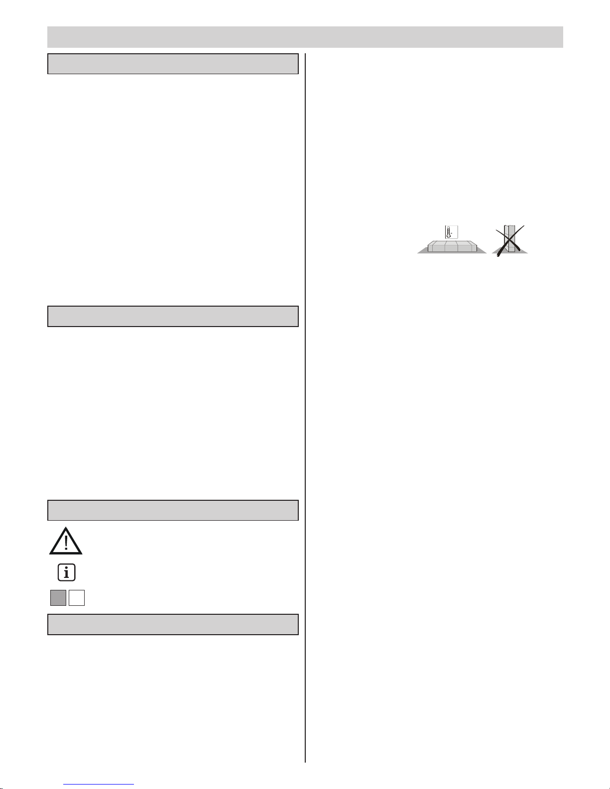
Storage Tips
• The drive mechanism may only be stored indoors, in a dry, sealed
environment at an ambient temperature of between -20°C and +50°C.
• The drive mechanism should be stored horizontally.
Operation-related Safety Instructions
• The drive mechanism may only be operated if a risk-free force tolerance
has been set. The force tolerance must be set as low as is required to
ensure that the door's closing force does not constitute a danger
(see 'Force Setting' section).
• Keep your hands clear of any moving door or any moving parts.
• Keep children, disabled persons and animals away from the door.
• Only drive into and out of the garage when the door is fully opened.
• Closing edges and workings of the door pose risk of injury.
Safety Instructions for Radio-controlled
Operation
• The radio remote control may only be used for equipment and systems in
which defective remote operation of the transmitter or receiver does not
constitute a risk to people, animals or objects, or in cases where this risk
is eliminated by means of additional safety facilities.
•
Use of the radio remote control in conjunction with equipment or systems
subject to an enhanced risk of accident (e.g. crane systems) is prohibited!
• To ensure safe operation, local safety regulations relevant to the
equipment concerned must be observed! Information regarding this can
be obtained from electricity suppliers, the VDE and employers' liability
insurance associations.
• The user must be made aware of the fact that the remote control of
equipment with accident risk potential may only occur, if at all, when the
equipment concerned is clearly visible.
• Radio remote control may only be used if movement of the door can be
supervised and there are no persons or objects in the area of movement.
• Store the manual remote control such that there is no risk of it being
accidentally operated by, for instance, children or animals.
GB
18
Rating Plate
EU Manufacturers' Declaration
The rating plate is located on the cover of the control unit housing.
The following is an example of a rating plate:
Technical Data
Important to note!
If the drive mechanism is installed by a company qualified to do
so, the company concerned must carry out an acceptance/
transfer test and fit a rating plate to the door. A copy of the test
protocol and the drive mechanism's Installation and Operation
Instructions should be kept by the operator.
• Doors that operate automatically by means of the drive mechanism must
comply with the following standards: EN 12604, EN 12605.
• The drive mechanism is intended for the exclusive purpose of opening
and closing the doors. Any other use does not constitute normal use.
• The manufacturer accepts no liability for damage resulting from use other
than normal use. The user accepts sole responsibility for any risk thereby
incurred.
• The drive mechanism may only be used if it is in a technically perfect
condition and in compliance with these Installation and Operating
Instructions (MBA) particularly regarding correct and responsible usage.
• Any defects that may impair the safe operation of the equipment should
be eliminated without delay.
• The gate wings must be stable and warp-proof, i.e. they should not bend
or warp during opening or closing operations.
• The drive mechanism is unable to compensate for any defects in the
door or for its incorrect installation.
• Only use the drive mechanism in a dry, indoor environment where there
is no risk of explosion.
• The ambient temperature for drive mechanism operation and storage is
between -20°C and +50°C. Should extreme weather conditions prevail,
consult your local stockist for advice.
Maximum door dimensions:
550 SL 800 SL 1100 SL
- max. width: 3500 mm 6000 mm 8000 mm
- max. height of canopy doors:
2600 mm 2600 mm 2600 mm
- max. height of vertical sectional doors:
2350 mm 2350 mm 2350 mm
With taller doors, corresponding rail extensions need to be installed - see
'Accessories' section.
- duty cycle: 40 % 40 % 40 %
Any other or non-compliant usage is deemed to be incorrect. The
manufacturer is not liable for any damage occurring as a result. The user is
responsible in such cases. Any warranty entitlement lapses.
Normal Use
Messrs.
SOMMER Antriebs- und Funktechnik GmbH
Hans-Böckler-Straße 21-27
D-73230 Kirchheim/Teck
hereby declares that the machine component designated below is intended
to be fitted into a gate mechanism and that commissioning is prohibited
until it has been ascertained that the installation in which this equipment is
to be fitted complies with all the relevant provisions of the applicable EU
directives.
Designation of machine component:
- marathon 550 SL garage door drive mechanism
- marathon 800 SL garage door drive mechanism
- marathon 1100 SL garage door drive mechanism
The relevant directives and standards are as follows:
- Machine Directive 98/37/EG
- Low Voltage Directive 73/23/EEC, Machine Directive 89/392/EEC
- EU Electromagnetic Compatibility Directive 89/336/EEC
Kirchheim, 01.07.2001 Uwe Sommer
Managing Director
marathon 550 SL 800 SL 1100 SL
Rated voltage: 230 230 230 V/AC
Rated frequency: 50/60 50/60 50/60 Hz
Maximum traction and
pressure force: 550 800 1100 N
Rated traction: 165 240 330 N
Rated current consumption: 0,7 0,8 0,9 A
Rated power consumption: 150 160 190 W
Maximum speed: 180 130 130 mm/s
Power consumption (stand-by): ~ 2 ~ 2 ~ 2 W
Operating temp. Range: -20 - +50 -20 - +50 -20 - +50 °C
Weight: 18 18,5 19 kg
Workplace-specific emission value < 75 dBA - drive only
Model : marathon 550 SL, FM 868 MHz
Manufacturer: SOMMER Antriebs- und Funktechnik GmbH
D-73230 Kirchheim/Teck
Article no.: 4200V000
Year built: 07/2001
Serial no.: ?
230V~ 50/60 Hz
150W/0.7A at 165N rated traction; max. 550N traction and pressure force
Operating temp. Range -20°C - +50°C
After-run distance <30mm; ED: 40% S3
Nur für trockene Räume
Use only in dry rooms
Seulement pour les chamdres séches
Safety Instructions for Authorised
Radio-controlled Operation
• The operator of this radio-controlled equipment is in no way protected
from interference from other telecommunications systems and facilities
(e.g. other radio-controlled equipment that is licensed to operate at the
same frequency range). Should serious interference be encountered,
please contact your nearest telecommunications office with interference
measuring facilities (radio signal localisation)!
• Under no circumstances may this radio-controlled equipment be linked to
any other telecommunications system without the express authorisation
of the relevant licensing authorities.
• Do not use the manually-operated remote control near locations or
installations that are susceptible to radio interference
(airports, hospitals).
GB
19
Door Types and Special Accessories*
* Accessories are not included in the delivery specification.
Door type Accessories
Up-and over, No special accessories required
Tracked door
Vertical sectional door with Vertical sectional door
single runner rail fitting with boomerang *
Vertical sectional door with Vertical sectional door
double runner rail fitting without boomerang *
Shutter-type door No accessories required
Canopy and non-protuding door Bow arm convertor system*
Swing door Swing-door fitting *
Side-opening sectional door Please consult specialist retailer
Installation Tips
• Check that all the parts have been supplied before you start installation
work in order to save time and unnecessary work if a part is missing.
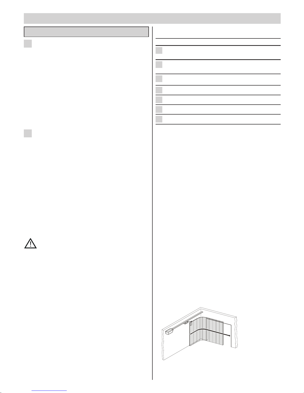
• The drive mechanism can be installed to one side of the door if it cannot
be installed at the centre. It is important to note that the door does not
bend as a result and jam in the guide rails.
Check
Open and close the door several times by hand holding it at the point
where you intend fitting the drive mechanism. If the door can be moved
in this way without difficulty (in compliance with the above forces), then
the drive mechanism can be fitted at this point.
• Emergency Release
In the case of a garage without a separate entrance (e.g. slip door), the
emergency release of the drive mechanism must be operable from the
outside. To this end, you should fit a Bowden wire or a release lock,
accessible from the outside. See 'Accessories' section.
• Door lock
With doors supplied without the current door locking system, opening
approximately 50 mm by hand, this should be replaced by a spring latch.
This spring latch can be connected across the locking set to the drive, so
that when the door opens the spring latch locks first and then the drive
starts to open the door. Spring latches can be built onto the left, right or
middle of the door. Ask your dealer for details.
• Canopy doors
As the mechanical lock of a door with a drive mechanism has to be
dismantled or activated, it is possible to open the door manually up to
approx. 50mm depending on the door construction.
In order to accommodate this, spring latches that lock the door in
addition to the drive can be mounted. These spring latches are
connected to the drive via a locking set in order to first unlock the spring
latches before a drive opens the door when opening the door.
• Installation should be carried out quickly and safely by two persons
• All-round or side-sectional door
The polarity of wires 12 + 13 of drives that have to push one the
above-mentioned doors open has to be changed. See marathon SL
Control Unit fig. 29.1 terminal 12 + 13.
7
6
5
4
4
4
3
Installation
Supplied Parts and Components
C-rails, chain with bogie unit and drive shaft
Control unit in housing, push-button cable, mains cable
Connecting element
Lintel fitting
Ceiling mounting
Installation accessories in bag comprising:
1 push-button
5 hexagon-head, self-tapping screws 6.5 x 19
4 wood screws 8 x 60
4 plugs S10
4 plain washers 8.4
Installation and Operating Instructions
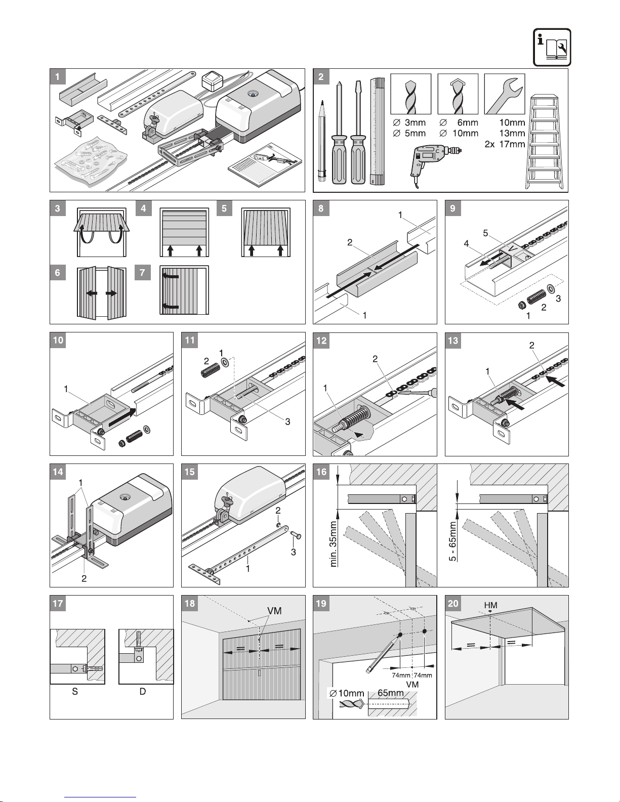
Tools Required
See Figure
Safety Tips
• Installation, connection and initial operation of the drive mechanism may
only be carried out by qualified specialists.
• Do not operate the door when people, animals and/or objects are in its
area of movement.
• Keep children, disabled persons and animals away from the door.
• Door installation should be carried out by two persons, thus ensuring
safe and fast completion of the work involved.
• Safety goggles should be worn when drilling the mounting holes.
• Cover the drive mechanism up when drilling to ensure it does not get
soiled.
Before Installation
Very important to note!
The walls and ceiling must be firm and stable. Only fit the
drive mechanism to a correctly aligned door. A door that has
not been aligned correctly can cause serious injuries.
• Doors that operate automatically by means of the drive mechanism must
comply with the following standards: EN 12604, EN 12605.
• Doors must be stable because they are subjected to high tensile and
compressive forces. Light doors made of plastic or aluminium must be
strenghtened before installation if necessary. Ask your specialist retailer
for advice.
• Remove door locking system or disable same.
• Check that the door runs easily.
• The door must be balanced.
Test :
Manually open the door half-way. It must stay still in this position. If the
door moves downards or upwards, mechanically readjust it. Ask your
specialist retailer for advice.
• If the drive mechanism requires a rail extension to be installed, it is
essential that the second ceiling mounting be fitted for this purpose.
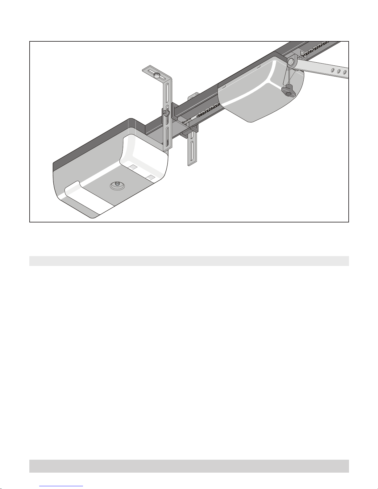
• Check the clearance between the door's highest up-position (THP, see
fig. 16) and the ceiling. The minimum clearance is 35 mm and the
maximum 100 mm, whereby the drive arm can only be at an angle of
max. 30°. If the clearance is less than is permissible, the drive
mechanism has to be moved back and an extended drive rail fitted.
Ask your local stockist for advice.
2
1
• Insert plug (1). Fit two screws (2) with plain washers (3). Tighten
screws securely.
• Align C-rail (4) at correct height. If necessary, move screws (5).
Tighten screws (5).
• Mount drive shaft (1):
Insert bolt (2) and push on retainer (3).
• Pull once on emergency release wire (N), thus disengaging bogie
unit (1). Tighten screw (8) on lintel fitting.
• Use drive shaft (2) to push bogie unit (1) as far forward as possible
(3). If necessary, release cut-off buffer (4).
• Align door fitting bracket (5) to door centre and mark out 5 holes. Drill
5 holes (Ø 5 mm).
Use screws that are appropriate to the door material.
Wear safety goggles when drilling!
• Insert 5 hexagon-head screws (6) and tighten securely.
• Release cut-off buffer (4) and push right up to bogie unit (7).
• Tighten cut-off buffer screw (4) securely.
• Release rear cut-off buffer (1) and push right back to stop (2). Open
door (3) by hand.
Shorten projecting ceiling brackets (4).
• Push cut-off buffer (1) right up to bogie unit (5). Securely tighten
screw on cut-off buffer (1).
Installing Slip-door Facility or Release Lock
• If your garage door is fitted with a slip door but no slip-door safety facility,
you need to have one installed (see 'Accessories' instructions).
• If your door has no slip door and your garage has no separate entrance,
install a release lock or Bowden wire to facilitate drive mechanism
release from the outside (see 'Accessories' instructions).
Fitting and Connecting Push-button
Very important to note!
When operating the push-button, the user should not stand in
the door's area of movement and must have a clear view of
the door.
Never run the push-button cable along a power cable as this can cause the
control unit to malfunction. The push-button cable is supplied connected to
the control unit.
• Install push-button (1) in an appropriate, easily accessible location
inside the garage. Minimum height from floor - 1.6 m.
Do not install the push-button in the door's area of movement.
• Install connection cable (2) inside the garage.
Connect end of cable to push-button (1).
Useful Tip!
The Funkcody, a radio-operated interior switch and a key switch
are other possible pulse generators that could be used. No
connecting cable to the drive mechanism need be fitted with the
Funkcody and the radio-operated interior switch. Contact your
local stockist for advice.
27
26
25
24
GB
20
Pre-assembling the Drive Mechanism
• Remove the drive mechanism from its packaging.
Dispose of the packaging correctly in accordance with local
requirements.
• Slot two C-rails (1) into connecting element (2) and push together as
far as they will go.
• Remove nut (1), spring (2) and plain washer (3).
• Push securing bolt (4) through opening in cut-off buffer (3).
• Push in lintel fitting (1).
• Push plain washer (1) and spring (2) on to securing bolt (3).
• Tighten nut (1) as far as mark. Hold chain back with screwdriver to
prevent movement.
Do not press against chain joint (2)!
• Move securing bolt (1) and chain with chain case (2) outwards as far
as stop.
• Unscrew two steel angle irons with length adjustment holes (1) and
screw onto ceiling bracket (2) as shown.
• Dismantle drive shaft (1):
pull retainer (2) out
remove bolt (3).
Installation of Drive Mechanism
• Determine door's highest up-position (THP):
Open door and measure smallest clearance (min. 35 mm) between
top edge of door and ceiling. The distance between the highest
up-position and the bottom edge of the C-rails has to be min. 5 mm
and may be max. 65 mm, whereas the drive arm can be at an angle
of max. 30°!
• The drive mechanism can be mounted on lintel (S) or ceiling (D).
• Measure front centre point (VM) of door and mark on door and on
lintel or ceiling.
• Make a mark 74 mm to right and left of centre of door (VM) at same
height on lintel or ceiling (see fig. 16).
• Drill two holes (Ø 10 x 65 mm).
Caution! Wear safety goggles when drilling!
Check thickness of ceiling, particularly with prefabricated
garages!
• Open door. Transfer door centre mark (HM) on to ceiling. Close door.
• Insert plug (1). Lift up drive mechanism (2) at front. Secure lintel
fitting (3) at front with two screws (4) and plain washers (5).
Caution!
Protect control unit housing (6) from damage!
• Lift up drive mechanism at back.
• Align ceiling bracket (1). Its final location ought to be in area B
between 0 and 600 mm.
Use a non-slip, stable stepladder!
• Align drive mechanism horizontally to rear centre of door (HM). Mark
position of holes. Drill two holes (Ø 10 x 65 mm deep).
Caution! Wear safety goggles when drilling!
Check thickness of ceiling, particularly with prefabricated
garages!
23
22
21
20
19
18
17
16
15
14
13
12
11
10
9
8
 Loading...