

Broadcast A/V Division
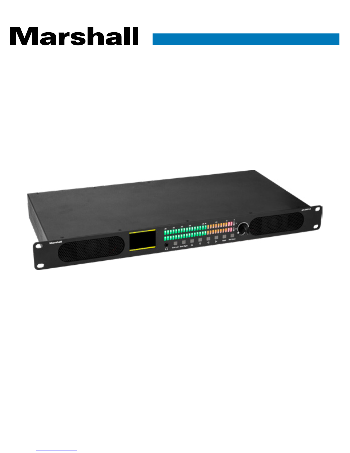
AR-DM51-B
Digital Audio Monitor
User Manual
Table of Contents
1. Introduction
2. Features
3. Package Contents
4. Front Panel
5. Control Buttons
6. Rear Panel
7. Specifications
8. Operation
9. Software
9.1. Connecting by Ethernet
9.2. Connecting by Serial Link
02
02
03
03
04
05
06
07
08
09
10
9.3. Using the Remote Control Application
Warranty
11
12
1

AR-DM51-B Manual
1. Introduction
The Marshall AR-DM51-B Digital Audio Monitor emphasizes a straight-forward, high-quality design
and simplicity of operation. The AR-DM51-B exceeds the capabilities of many larger 2RU designs,
and is equally at home in production fly packs, news vans, remote OB vans, and equipment rooms.
2. Features
High Performance Audio
• Matches or exceeds many larger 2RU designs
• Enough “punch” for the noisiest server rooms (up to 100dB)
Multiple Input Types
• 3G SDI with Looping Output
• HDMI
• Analog XLR Balanced - 2 Channels
• Analog RCA Unbalanced Line Level - 2 Channels
Flexible Output Types
• AES-EBU Pair Balance XLR (110-ohms)
• Analog Unbalanced RCA Line Level - 2 Channels
2” Video Display
• Provides confidence image of selected HDMI or SDI source
• Text indicates Source, Format, Selected Channels and more
Controllable via Ethernet or RS-232 Serial
• Control application downloadable from Marshall website
• Select audio scale types, sources, etc.
Compact 1RU Design Saves Rack Space
• Minimum size
• Low power consumption, low heat emission into rack
www.marshall-usa.com 2
3. Package Contents
Please ensure the following are included:
• One AR-DM51-B Main Chassis
• One 12-Volt Universal Power supply (120/240V – 50/60Hz)
Additionally, free control software is available for download on the Marshall website. Visit www.
marshall-usa.com for more information.)
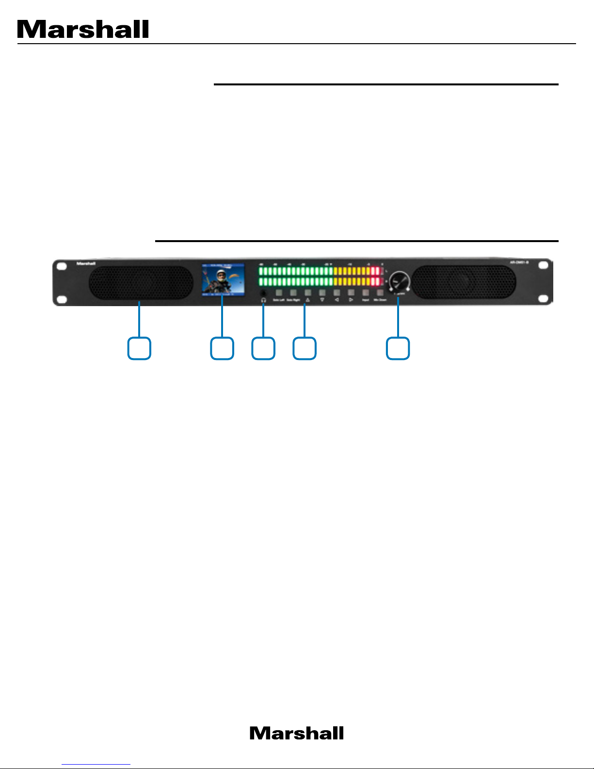
4. Front Panel
1 3 4 52
1. Speakers
Provides sound from two channels except when Solo Buttons are pressed.
2. LCD Video Display
When an HDMI or SDI source is being monitored, the associated video will appear here. Also a
text overlay shows input source, selected audio channels, and source video parameters.
Note: The LCD display will be black when Analog Sources are selected.
3. Headphone Jack
Designed to accept stereo headphones with 3.5mm plug.
4. Control Buttons
Provides quick access for standard equipment operation.
5. Volume / Mute Knob
Turn the knob to adjust the sound level of both speakers.
Press in on the knob to instantly Mute the speakers.
3

5. Control Buttons
1. Solo Left & Solo Right
Press one of these to isolate the left or right channel only.
Note: Sound will come out of both speakers when a solo channel is selected but will originate
from a single source.
AR-DM51-B Manual
1 2 3 4 5
2. Left / Right Arrow Buttons
Press the Left Arrow button to select a lower numbered pair of channels, press the Right Arrow
button to select a higher numbered pair of channels.
For example, when monitoring channels 3 & 4, pressing Left Arrow will switch to channels 1 &
2, pressing Right Arrow will switch to channels 5 & 6. The lower-numbered channel audio in a
selected pair will play from the Left speaker. The higher-numbered channel audio will play from
the Right speaker.
3. Up / Down Arrow Buttons
Press the Up Arrow to select channel group 1 – 8, press the Down Arrow to select channel
group 9 – 16.
Note: This applies to SDI sources only
4. Input
Press to change input source (input type) in this order:
• HDMI
• SDI
• Analog (XLR Balanced)
• Analog (RCA Unbalanced)
5. Down Mix
The button on the far right provides a stereo mix from 5.1 or 7.1 surround sources.
www.marshall-usa.com 4

6. Rear Panel
1 2 4 5 6 7 8 9 103
1. Power Switch
2. 12-Volt DC Power Input XLR 4-pin
3. RS-232 Serial Control 9-pin D-Sub Port
4. Ethernet Control RJ-45 Port
5. HDMI Input
6. SDI Input and Loop Out
7. Analog Balanced XLR Inputs (2 channels)
8. AES/EBU Output XLR (2 channel pair)
9. Stereo Unbalanced Input 2 channel RCA jacks
10. Stereo Unbalanced Output 2 channel RCA jacks
5

7. Specifications
AR-DM51-B Manual
Model Name
Tech nic al
Video Inputs
Video Formats Supported
HDMI HDCP
Audio Inputs
Audio Outputs
Digital Audio Supported
HDMI connector
Serial Control Connector
Network Connector
Mechanical & Electrical
Housing
Dimensions [H x W x D]
Weight
Mounting
Included Power supply
Power consumption
Operation temperature
Storage temperature
ESD protection
Relative humidity
AR-DM51-B
HDMI 2.0 x 1
3G SDI x 1 with looping output
HDMI Up to 4K2K@60fps (4:4:4 sampled 8-bits)
SDI up to 1080p50, 59.94,60 (4:2:2 sampled 10-bits)
HDCP 2.2 and 1.4 Supported
Analog Balanced x 2 XLR Female
Analog Unbalanced x 2 RCA Jack
AES/EBU x 1 (Digital Pair) XLR Male
Analog Unbalanced x 2 RCA Jack
PCM 2, 5.1, 7.1 channels
HDMI type A
DE-9 [9-pin D-sub female] supports RS-232
WE/SS 8P8C for control via Ethernet
Metal enclosure
1.75” X 19” x 8.5” / 4.45 cm x 48.25 cm x 21.6 cm
7.3 lbs / 3.3 Kg
Chassis has “ears” for standard 19” rack mount
DC 12-Volts 5-Amps 4-pin XLR connector
6 Watts Avg
0~40 C [32~104 F]
-20~60 C [-4~140 F]
Human body model — ±15kV [air-gap discharge] & ±8kV [contact
discharge]
20~90% RH [no condensation]
www.marshall-usa.com 6

8. Operation
Controls on the AR-DM51-B are designed to be extremely straight-forward. To start, simply press
the Input button to select the desired source, then adjust the volume knob to the desired listening
level.
Metering Type
The default audio metering type is PPM (Peak Program Meter). The metering type can be switched
to VU (averaging) using the remote control software (available from the Marshall website at:
www.marshall-usa.com/)
Monitoring HDMI Sources
When HDMI is selected, video from that source will appear on the front panel LCD display along
with information about the video format and selected audio channels. This is a convenient feature
allowing quick confirmation that the desired source is being monitored. Channels 1 & 2 will appear
on the LED meters and be heard from the speakers. Up to 8 audio channels may be carried in an
HDMI program. These are often arranged as 5.1 or 7.1 surround. Use the Right or Left arrow buttons
to hear other channel pairs or press the Mix Down button to hear all of the channels as a stereo mix.
Monitoring SDI Sources
When SDI is selected, video from that source will appear on the front panel LCD display along with
information about the video format and selected audio channels. Channels 1 & 2 will appear on the
LED meters and be heard from the speakers. SDI can carry up to 16 channels, organized as two
groups of 8 channels each. Press the Right or Left arrow buttons to hear other channels in the first
group (channels 1 – 8).
Press the Up or Down arrows to select the second group (channels 9 – 16) then press Left or Right
to select channels in this group.
Monitoring Analog Sources
Connectors are provided for either broadcast level +4DBm balanced audio (XLR) or AV line level
-10dBm unbalanced (RCA) audio. Broadcast level tone at +4dBm will indicate at the arrow mark
on the meter bar, line level 10 at -10dBm will indicate at the same point when connected via the
RCA connectors.
In addition to metering and monitoring, analog sources are sampled and converted to AES digital
and will appear at the AES/EBU connector on the back panel. The AES connection is balanced
110-ohm type.
Note: If it is desired to connect to equipment that accepts AES digital audio on a 75-ohm BNC
connector, please use a 110-ohm to 75-ohm “balun” converter.
7

AR-DM51-B Manual
9. Software
A free application is available for download from the Marshall Electronics website at: www.marshallusa.com/. The AR-DM51-B may be operated and configured from a Windows® computer either by
an Ethernet or Serial (RS-232) link.
Download and unzip and extract the file “xxxx.exe” to a folder or to the desktop. Double-click the
file and it will open immediately and appear similar to this:
www.marshall-usa.com 8

9.1 Connecting by Ethernet
To control the AR-DM51-B using an Ethernet connection, first select the “Telnet” radio button in the
upper left corner, then select “Static IP” if you wish to enter IP parameters manually. Select “DHCP”
if the IP address will be automatically assigned from a network router or DNS server.
Next, click the “Connect” button to establish a connection between the PC and the audio rack.
When connection is successful, the MAC address of the audio rack will appear in the window at
the bottom.
9

AR-DM51-B Manual
9.2 Connecting by Serial Link
To control the AR-DM51-B using an RS-232 serial link, first select the “RS232” radio button, then
select the port number. The correct port number will likely be the one with the highest numeric
value.
Note: A serial connection will require either a serial port on the PC or a serial adapter device most
likely attached to the computer by USB. The most common connector type will be a 9-pin DSub
similar to the one on the back of the AR-DM51-B. When that is the case, a successful connection
can be made using a “Null Modem Cable” or making a cable like this:
Computer AR-DM51-B
Pin 2 ---------------- Pin 3 (Tx to Rx)
Pin 3----------------- Pin 2 (Rx to Tx)
Pin 5 ---------------- Pin 5 (Ground)
www.marshall-usa.com 10

9.3 Using the Remote Control Application
Once a connection has been established between the control application and the AR-DM51-B,
operation is simply a matter of clicking on the desired functions.
All of the front panel functions can be operated through the control application screen.
In addition, the metering scale can be switched between VU-Mode (averaging) and DPPM-Mode
(instantaneous peak-reading).
Also, there are controls for the front panel video display Brightness, Contrast, and Color Saturation.
When a firmware update is issued for the AR-DM51-B, the Firmware Update button will initiate the
update process. Updates may be performed over Ethernet or RS-232 serial link. Please follow the
latest instructions included with the update as procedures may change with the update.
The Factory Reset button returns all LCD monitor settings to their mid position.
11

Warranty
Marshall Electronics warranties to the first consumer that this device will, under normal use,
be free from defects in workmanship and materials, when received in its original container, for
a period of two years from the purchase date. This warranty is extended to the first consumer
only, and proof of purchase is necessary to honor the warranty. If there is no proof of purchase
provided with a warranty claim, Marshall Electronics reserves the right not to honor the warranty
set forth above. Therefore, labor and parts may be charged to the consumer. This warranty
does not apply to the product exterior or cosmetics. Misuse, abnormal handling, alterations or
modifications in design or construction void this warranty. No sales personnel of the seller or
any other person is authorized to make any warranties other than those described above, or to
extend the duration of any warranties on behalf of Marshall Electronics, beyond the time period
described above.
Due to constant effort to improve products and product features, specifications may change
without notice.
Safety
Listening to audio at excessive volumes can cause permanent hearing damage. Over exposure
to excessive sound levels can damage your ears resulting in permanent noise-induced hearing
loss (NIHL). Please use the following guidelines established by the Occupational Safety Health
Administration (OSHA) on maximum time exposure to sound pressure levels before hearing damage
occurs.
dB SPL Level
100
Maximum time exposure
8 hours
90
4 hours
95
2 hours
20608 Madrona Avenue, Torrance, CA 90503
Tel: (800) 800-6608 / (310) 333-0606 • Fax: 310-333-0688
www.marshall-usa.com
support@marshall-usa.com
V.1. 0
 Loading...