

Page 1

PMD-750
Wireless Camera Mount System
User Guide
Guía del usuario
Guide d’utilisation
Guida per l’uso
Benutzerhandbuch
Appendix
English (3–11)
Español (12–20)
Français (21–29)
Italiano (30–38)
Deutsch (39–47)
English (48–50)
Page 2

2
Page 3

User Guide (English)
Introduction
Box Contents
PMD-750 Transmitter
PMD-750 Receiver
Lavalier Condenser Mic
Foam Windscreen
Synthetic Fur Windscreen
Hot Shoe Adapter
Mini-XLR Audio Output Cable
User Guide
Safety & Warranty Manual
Support
For the latest information about this product (documentation, technical
specifications, system requirements, compatibility information, etc.) and
product registration, visit marantzpro.com.
For additional product support, visit marantzpro.com/support.
3
Page 4

Important Safety Precautions
Please note: Marantz Professional and inMusic are not responsible for the
use of its products or the misuse of this information for any purpose. Marantz
and inMusic are not responsible for the misuse of its products caused by
avoiding compliance with inspection and maintenance procedures. Please
also refer to the included safety and warranty manual for more information.
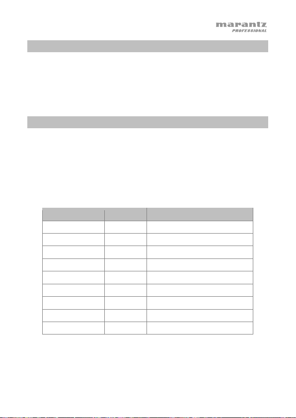
Sound Level
Permanent hearing loss may be caused by exposure to extremely high noise
levels. The U.S. Occupational Safety and Health Administration (OSHA) has
specified permissible exposures to certain noise levels. According to OSHA,
exposure to high sound pressure levels (SPL) in excess of these limits may
result in hearing loss. When using equipment capable of generating high
SPL, use hearing protection while such equipment is under operation.
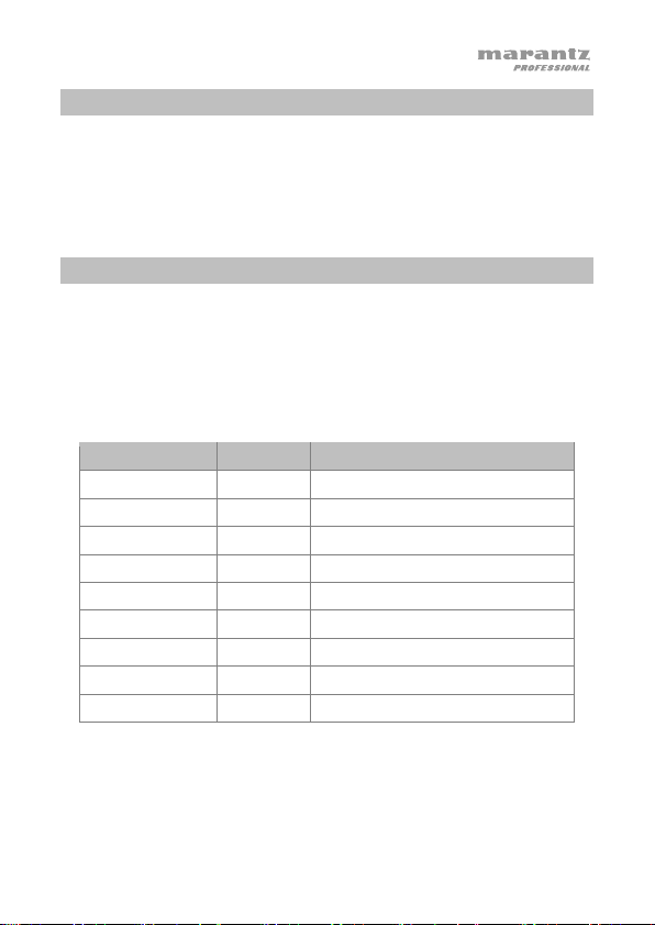
Hours per daySPL (dB) Example
8 90 Small gig
6 92 Train
4 95 Subway train
3 97 High level desktop monitors
2 100 Classical music concert
1.5 102 Riveting machine
1 105 Machine factory
0.50 110 Airport
0.25 or less 115 Rock concert
4
Page 5
1
2
1
3
1
2
3
4
5
1
2
1
3
1
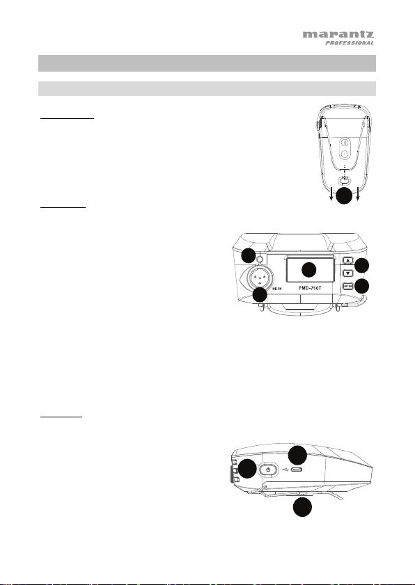
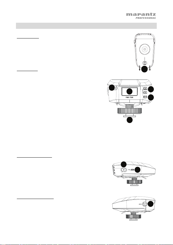
Features
Transmitter
Bottom Panel
1. Battery Compartment: Insert (2) AA batteries here (not
included). Alkaline batteries are recommended; always replace
both batteries. Do not mix battery types.
Front Panel
1. Display: The display will show the
channel that the unit is communicating
on, pairing status, and battery level
meter.
2. Pair LED: The LED will blink red when
the transmitter is muted. The LED will
blink blue when it is searching to pair to
the receiver. The LED will be lit solid blue
when it is paired to the receiver.
3. Navigation Buttons: Press these
buttons to change which sections of the
display are highlighted.
4. Enter Button: Press this button to
navigate to a menu/submenu selection or
confirm a specific function.
5. Mic Input: Connect the included mini-
XLR lavalier condenser microphone here.
Side Panel
1. Micro USB Port: Connect a USB
power adapter (sold separately) here to
power the unit if not using 2 AA
batteries.
2. Power On/Off: Press and hold this
button to power the unit on/off.
3. Belt Clip: Attach this clip to secure to a
belt loop or pocket.
5
Page 6
1
1
2
2
3
1
1
3
2
4
1
1
1
2
5
1
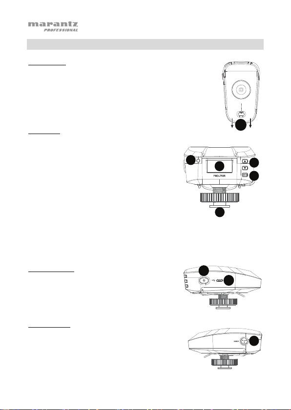
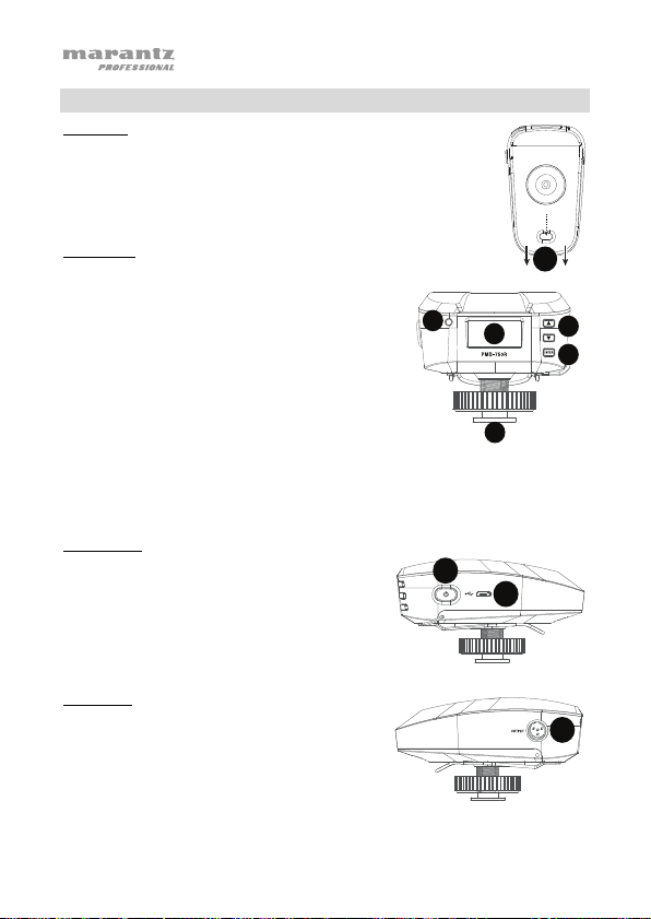
Receiver
Bottom Panel
1. Battery Compartment: Insert (2) AA batteries here (not
included), and make sure the positive (+) and negative (–) poles
are facing the proper directions. Alkaline batteries are
recommended. Always replace both batteries, and do not mix
battery types.
Front Panel
1. Display: The display will show the channel that
the unit is communicating on, pairing status,
and battery level meter.
2. Pair LED: The LED will be lit solid red when
unpaired from the transmitter. The LED will be lit
solid blue when it is paired to the transmitter.
3. Navigation Buttons: Press these buttons to
change which sections of the display are
highlighted.
4. Enter Button: Press this button to navigate to a
menu/submenu selection or confirm a specific
function. Quickly press and release this button
to change TX1 and TX2 pages on the main
menu.
5. Hot Shoe Adapter Mount: Attach this to the
hot shoe mount of a DSLR camera.
Right Side Panel
1. Micro USB Port: Connect a USB power
adapter (sold separately) here to power the unit
if not using 2 AA batteries.
2. Power On Button: Press and hold this button
to power the unit on/off.
Left Side Panel
1. Audio Output: Using the included mini-XLR
6
cable, connect this audio output to the
microphone input of a DSLR camera.
Page 7
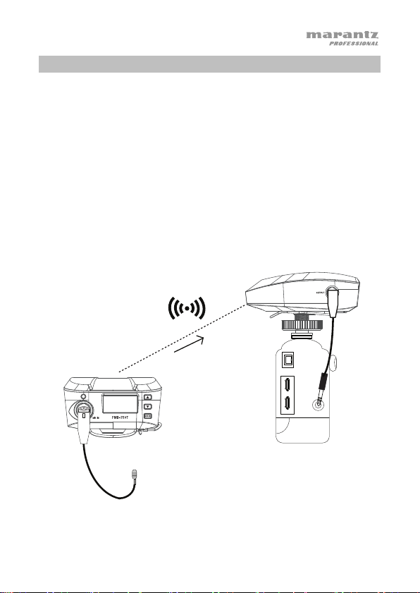
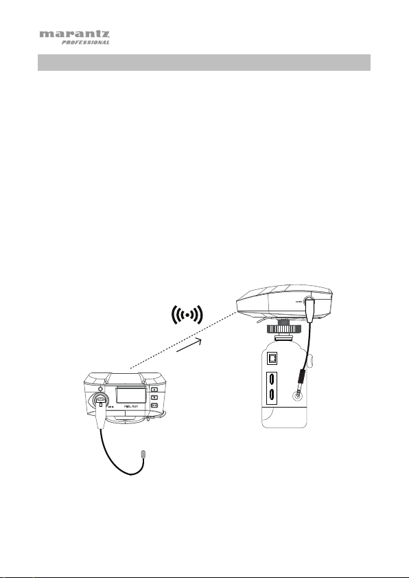
Setup
Items not listed under Introduction > Box Contents are sold separately.
Example 1 – Mono Operation
To send a mono signal from a single transmitter to the receiver:
1. Connect your microphone to the mic input on the transmitter, and connect the
receiver’s audio output to your camera’s external mic input. Keep the volume
controls on the camera at its minimum settings.
2. If necessary, adjust the RF dB level on the transmitter
better operating range and noise resistance.
3. Turn on your camera, adjust the RX output level on the receiver and the input level
of the camera’s external mic input to hear the audio signal (or view the level on the
input level of the camera).
4. In the audio recording settings on your camera, make sure it is set to Manual rather
than Auto. Check the input level meter, and adjust the level so that the loudest
sounds peak around -12 dB. Make sure the sound does not exceed 0 dB, which will
cause the signal to distort.
Receiver
Transmitter
to get a strong signal for
Camera
Mic
Input
7
Page 8
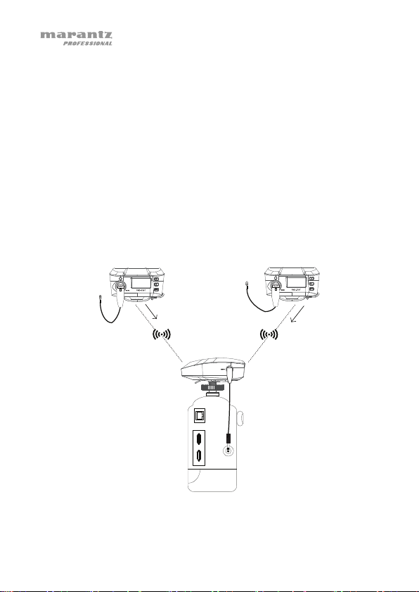
Example 2 – Stereo Operation
To send a stereo signal from 2 transmitters to the receiver:
1. Connect your microphones to the mic inputs on the transmitters, and connect the
receiver’s audio output to your camera’s external mic input. Keep the volume
controls on the camera at its minimum settings.
2. If necessary, adjust the RF dB level on the transmitter
better operating range and noise resistance.
3. Turn on your camera, adjust the RX output level on the receiver, and the input
level of the camera’s external mic input to hear the audio signal (or view the level
on the input level of the camera).
4. In the audio recording settings on your camera, make sure it is set to Manual
rather than Auto. Check the input level meter, and adjust the level so that the
loudest sounds peak around -12 dB. Make sure the sound does not exceed 0 dB,
which will cause the signal to distort.
5. Set the receiver’s Output menu to Stereo and adjust the output level to get a
strong signal without clipping.
to get a strong signal for
Transmitter
Transmitter
Camera Mic Input
8
Page 9
Operation
To set up and use your PMD-750, follow the steps in the Pairing the Transmitter and
Receiver chapter in order. If you are setting up a system using two transmitters, set up
each transmitter one at a time, and keep each transmitter powered on as you set up the
additional unit.
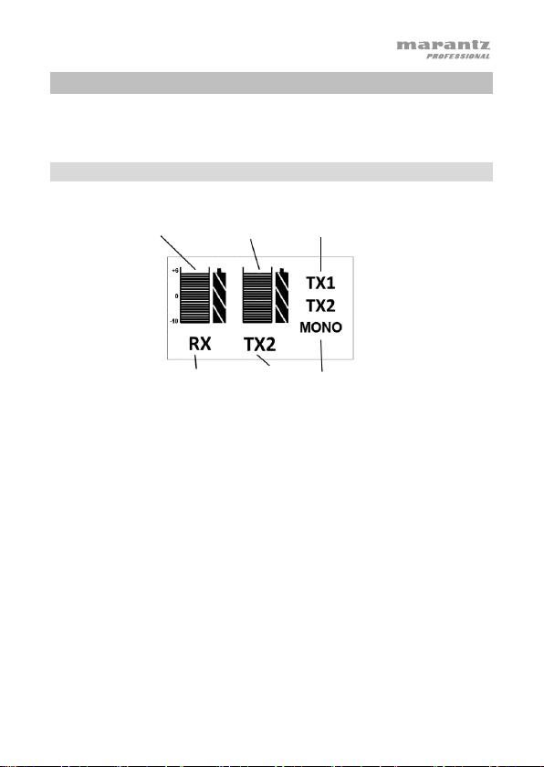
Receiver Menu
Receiver battery and
output meter/level
setting
Transmitter
battery and signal
indicator
Pairing Mode:
Output Level:
Output (this function is only available when 2 transmitters are paired):
Receiver/Pairing
• Press the navigation buttons to move the cursor to the RX icon. Once RX
is highlighted, the icon will display PAIR. Press Enter to go into pairing
mode and the icon will flash to wait for TX1 or TX2 pairing. Once paired, the
icon will be lit solid.
• Press and release the Enter button on the receiver to highlight the meter
and use the navigation buttons to adjust the receiver output level.
• Press and release the Enter button on the receiver to toggle between mono
and stereo modes. The receiver will output in mono if only one transmitter is
paired.
Transmitter
1 or 2
(if two are paired)
Mono or Stereo
output from
Transmitter 1
Transmitter 2
receiver
9
Page 10
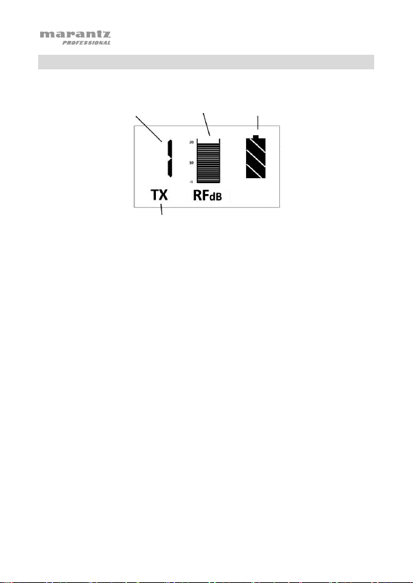
g
Transmitter Menu
The number of paired
transmitters (in the
order that they were
paired)
Main Menu:
• Mute/unmute the transmitter by quickly pressing and releasing the Power
Pairing Mode:
RF Level:
button.
• Press the navigation buttons to move the cursor to the TX icon. Once TX is
highlighted, the icon will display PAIR. Press Enter to go into pairing mode
and the icon will flash to wait for the receiver to pair. Once paired, the icon
will be lit solid.
• Press and release the Enter button on the receiver to highlight the meter
and use the navigation buttons to adjust the RF power. The default setting
is 10 dBm. You can set this to: -1, 3, 5, 8, 10, 12, 14, 16, 20 dBm.
RF Power Setting
Transmitter/Pairin
Transmitter Battery
Level
10
Page 11
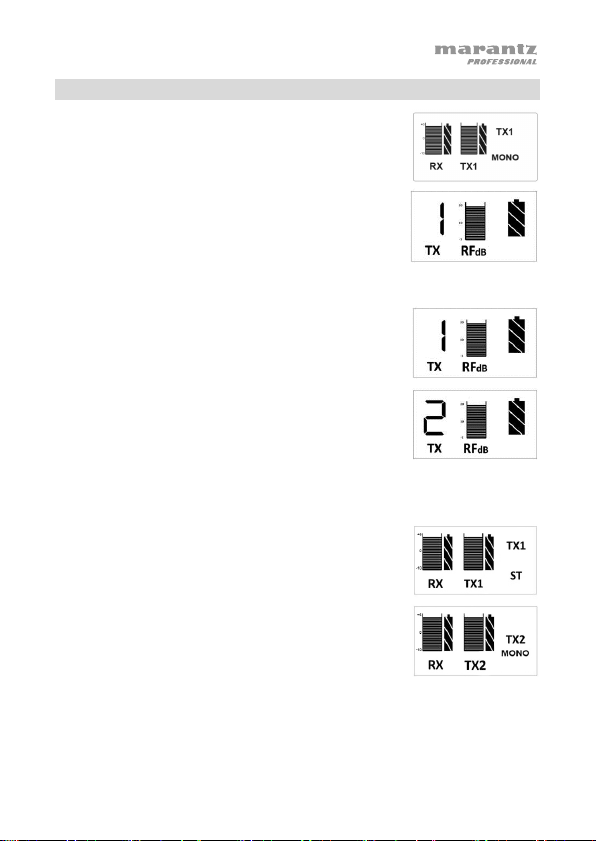
Pairing the Transmitter and Receiver
Pairing 1 transmitter with the receiver (automatic):
1. Turn on the receiver and it will enter pairing mode.
2. Turn on the transmitter and it will automatically pair
with the receiver.
Pairing 2 transmitters with the receiver (automatic):
1. Turn on the receiver and it will enter pairing mode.
2. Turn on the transmitters and they will enter pairing
mode. The first transmitter will automatically pair with
the receiver.
3. Once Transmitter 1 is paired, Transmitter 2 will pair to
the receiver. When Transmitter 2 is paired to the
receiver, the transmitter display will show “2 TX”.
4. The receiver display will show "Mono" or "Stereo".
Press Enter to select it and use the navigation
buttons to switch between "Mono" and "Stereo".
Press Enter to confirm the choice.
Pairing 1 or 2 transmitters to the receiver (manual)
1. Turn on the receiver and transmitter(s).
2. Press the navigation buttons to move the cursor to the
TX icon. Once TX is highlighted, the icon will display
PAIR. On the transmitter(s), press Enter to go into
pairing mode and the icon will flash to wait for the
receiver to pair. Once paired, the icon will be lit solid.
3. The receiver display will show "Mono" or "Stereo".
Press Enter to select it and use the navigation buttons
to switch between "Mono" and "Stereo". Press Enter to
confirm the choice.
Note: The Output mode is automatically set to “Mono”
when only one transmitter is paired.
11
Page 12

Guía del usuario (Español)
Introducción
Contenido de la caja
Transmisor PMD-750
Receptor PMD-750
Micrófono condensador de corbata
Paraviento de espuma de polietileno
Paraviento de piel sintética
Adaptador para zapata para cámara
Cable de audio mini-XLR de salida
Guía del usuario
Manual sobre la seguridad y garantía
Soporte
Para obtener la información más reciente acerca de este producto
(documentación, especificaciones técnicas, requisitos de sistema,
información de compatibilidad, etc.) y registrarlo, visite marantzpro.com.
Para obtener soporte adicional del producto, visite marantzpro.com/support.
12
Page 13
Precauciones importantes para la seguridad
Para tener en cuenta: Marantz Professional e inMusic no son responsables
por el uso de sus productos o el mal uso de esta información para cualquier
propósito. Marantz e inMusic no son responsables del mal uso de sus
productos causados por la omisión del cumplimiento de los procedimientos
de inspección y mantenimiento. Para más información, consulte también el
manual de seguridad y garantía incluido.
Nivel de sonido
La exposición a niveles muy altos de ruido puede causar pérdidas auditivas
permanentes. La Administración de Seguridad y Salud Ocupacional de
EE.UU. (OSHA) ha especificado los niveles de exposición permisibles a
ciertos niveles de ruido. Según la OSHA, la exposición a niveles de presión
sonora (SPL) elevados que excedan estos límites puede causar pérdidas
auditivas. Cuando utilice equipos capaces de generar SPL elevados, use
protecciones auditivas mientras dichos equipos están en funcionamiento.
Horas diarias SPL (dB) Ejemplo
8 90 Música de bajo volumen
6 92 Tren
4 95 Tren subterráneo
3 97 Monitores de escritorio de alto nivel
2 100 Concierto de música clásica
1,5 102 Remachadora
1 105 Máquina fabril
0,50 110 Aeropuerto
0,25 o menos 115 Concierto de rock
13
Page 14

1
2
1
3
1
2
3
4
5
1
2
1
3
1
Características
Transmisor
Panel trasero
1. Compartimiento para pilas: Inserte aquí (2) pilas AA (no
incluidas). Se recomiendan pilas alcalinas; siempre reemplace
ambas pilas. No mezcle pilas de diferentes tipos.
Panel frontal
1. Pantalla: La pantalla mostrará el canal a
través del cual se está comunicando la
unidad, el estado de apareamiento y el
indicador de nivel de las pilas.
2. LED Pair: El LED parpadeará con luz
roja si el transmisor está silenciado.
Parpadeará con luz azul cuando esté
buscando el receptor para aparearse. El
LED se iluminará de color azul
permanentemente cuando esté apareado
con el receptor.
3. Botones de navegación: Pulse estos
botones para cambiar las secciones que
se resaltan en la pantalla.
4. Botón Enter: Pulse este botón para
navegar a la selección de un
menú/submenú o confirmar una función específica.
5. Entrada para micrófono: Conecte aquí el cable mini-XLR del micrófono
condensador de corbata.
Panel lateral
1. Puerto micro USB: Conecte aquí un
adaptador de alimentación USB (se vende
por separado) para suministrar corriente a la
unidad si no está utilizando las 2 pilas AA.
2. Encendido/apagado: Mantenga pulsado
este botón para encender y apagar la unidad.
3. Presilla para cinturón: Añada este clip para
sujetarlo de una hebilla del cinturón o bolsillo.
14
Page 15
1
1
2
2
3
1
1
3
2
4
1
1
1
2
5
1
Receptor
Panel trasero
1. Compartimiento para pilas: Inserte aquí (2) pilas AA (no
incluidas) y asegúrese que los polos positivo (+) y negativo (–)
estén orientados correctamente. Se recomienda utilizar pilas
alcalinas. Siempre reemplace ambas pilas y no mezcle pilas de
diferentes tipos.
Panel frontal
1. Pantalla: La pantalla mostrará el canal a
través del cual se está comunicando la unidad,
el estado de apareamiento y el indicador de
nivel de las pilas.
2. LED Pair: El LED se iluminará de color rojo
permanentemente cuando se desaparee del
receptor. El LED se iluminará de color azul
permanentemente cuando esté apareado con
el transmisor.
3. Botones de navegación: Pulse estos botones
para cambiar las secciones que se resaltan en
la pantalla.
4. Botón Enter: Pulse este botón para navegar a
la selección de un menú/submenú o confirmar una función específica. Pulse y
suelte rápidamente este botón para cambiar las páginas TX1 y TX2 en el menú
principal.
5. Adaptador para zapata para cámara: Sujételo a la zapata de una cámara DSLR.
Panel lateral derecho
1. Puerto micro USB: Conecte aquí un adaptador
de alimentación USB (se vende por separado)
para suministrar corriente a la unidad si no está
utilizando las 2 pilas AA.
2. Botón de encendido: Mantenga pulsado este
botón para encender y apagar la unidad.
Panel lateral izquierdo
1. Salida de audio: Utilizando el cable mini-XLR
incluido, conecte esta salida de audio a la entrada
para micrófono de una cámara DSLR.
15
Page 16
Instalación
Los elementos que no se enumeran en Introducción > Contenido de la caja se venden
por separado.
Ejemplo 1 – Funcionamiento en mono
Cómo enviar una señal mono desde un transmisor individual al receptor:
1. Conecte su micrófono a la entrada mic del transmisor y conecte la salida de
audio output del receptor a la entrada para micrófono externo de su cámara.
Mantenga los controles de volumen de la cámara en sus ajustes mínimos.
2. De ser necesario, ajuste el nivel de RF dB en el transmisor para obtener una señal
fuerte y lograr un mayor alcance de funcionamiento y resistencia al ruido.
3. Encienda su cámara, ajuste el nivel de la salida RX del receptor y el nivel de la
entrada para micrófono externo de la cámara a fin de poder escuchar la señal de
audio (u observar el nivel en el nivel de entrada de la cámara).
4. En los ajustes de grabación de audio de su cámara, asegúrese de que esté
ajustada en Manual en lugar de Auto. Compruebe el medidor de nivel de entrada
y ajústelo de manera que los sonidos más fuertes no superen los -12 dB.
Asegúrese de que el sonido no exceda los 0 dB, lo cual distorsionará la señal.
16
Transmisor
Receptor
Cámara
Micrófono
Entrada
Page 17

Ejemplo 2
Cómo enviar una señal estéreo desde 2 transmisores al receptor:
1. Conecte sus micrófonos a la entradas mic de los transmisores y conecte la
2. De ser necesario, ajuste el nivel de RF dB en el transmisor para obtener una señal
3. Encienda su cámara, ajuste el nivel de la salida RX del receptor y el nivel de la
4. En los ajustes de grabación de audio de su cámara, asegúrese de que esté
5. Coloque el menú de salida del receptor en Stereo y ajuste el nivel de salida para
– Funcionamiento en estéreo
salida de audio output del receptor a la entrada para micrófono externo de su
cámara. Mantenga los controles de volumen de la cámara en sus ajustes mínimos.
fuerte y lograr un mayor alcance de funcionamiento y resistencia al ruido.
entrada para micrófono externo de la cámara a fin de poder escuchar la señal de
audio (u observar el nivel en el nivel de entrada de la cámara).
ajustada en Manual en lugar de Auto. Compruebe el medidor de nivel de entrada
y ajústelo de manera que los sonidos más fuertes no superen los -12 dB.
Asegúrese de que el sonido no exceda los 0 dB, lo cual distorsionará la señal.
obtener una señal intensa sin recorte.
Transmisor
Transmisor
Receptor
Entrada para
micrófono de la
cámara
17
Page 18

de nivel
Medidor de señal
y pila del
transmisor
Transmisor 1
Transmisor 2
(si se aparean dos)
Funcionamiento
Para configurar y utilizar su PMD-750, siga los pasos en el capítulo Apareamiento del
transmisor y receptor en orden. Si está instalando un sistema con dos transmisores,
instale cada transmisor de a uno a la vez y mantenga cada transmisor encendido a
medida que instala la unidad adicional.
Menú del receptor
Indicador de señal y
pila del receptor/ajuste
Receptor/apareamiento
Modo de apareamiento:
• Pulse los botones de navegación para mover el cursor hasta el icono RX.
Una vez que RX esté resaltado, el icono mostrará PAIR. Pulse Enter para
entrar en modo de apareamiento y el icono parpadeará mientras espera
que TX1 o TX2 se apareen. Una vez apareado, el icono quedará encendido
Nivel de salida:
Salida (esta función sólo está disponible cuando se aparean 2 transmisores):
18
permanentemente.
• Mantenga pulsado el botón Enter en el receptor para resaltar el medidor y
utilizar los botones de navegación para ajustar el nivel de salida del
receptor.
• Pulse y suelte el botón Enter en el receptor para conmutar entre los modos
mono y estéreo. El receptor emitirá en mono si sólo se aparea un transmisor.
Transmisor
Salida mono o
estéreo del
receptor
Page 19

Menú del transmisor
La cantidad de
transmisores
apareados (en el orden
en el que se aparearon)
Menú principal:
• Silencie/anule el silenciamiento del transmisor pulsando y soltando
Modo de apareamiento:
Nivel de RF:
rápidamente el botón Power.
• Pulse los botones de navegación para mover el cursor hasta el icono TX.
Una vez que TX esté resaltado, el icono mostrará PAIR. Pulse Enter para
entrar en modo de apareamiento y el icono parpadeará mientras espera
que el receptor se aparee. Una vez apareado, el icono quedará encendido
permanentemente.
• Mantenga pulsado el botón Enter en el receptor para resaltar el medidor y
utilizar los botones de navegación para ajustar la potencia de RF. El valor
predeterminado es 10 dBM. Puede ajustarla en: -1, 3, 5, 8, 10, 12, 14, 16,
20 dBm.
Ajuste de
potencia
de RF
Transmisor/apareamiento
Nivel de la pila del
transmisor
19
Page 20

Apareamiento del transmisor y receptor
Apareamiento de 1 transmisor con el receptor
(automático):
1. Encienda el receptor y entrará en modo de
apareamiento.
2. Encienda el transmisor y se apareará automáticamente
con el receptor.
Apareamiento de 2 transmisores con el receptor (automático):
1. Encienda el receptor y entrará en modo de
apareamiento.
2. Encienda los transmisores y entrarán en modo de
apareamiento. El primer transmisor se apareará
automáticamente con el receptor.
3. Una vez apareado el transmisor 1, el transmisor 2 se
apareará con el receptor. Cuando el transmisor 2 se
aparea con el receptor, aparecerá “2 TX” en la pantalla
del transmisor.
4. La pantalla del receptor mostrará “Mono” o “Stereo”.
Pulse Enter para seleccionarlo y utilice los botones de
navegación para conmutar entre “Mono” y “Stereo”.
Pulse Enter para confirmar su selección.
Apareamiento de 1 o 2 transmisores con el receptor (manual):
1. Encienda el receptor y el/los transmisor(es).
2. Pulse los botones de navegación para mover el cursor
hasta el icono TX. Una vez que TX esté resaltado, el
icono mostrará PAIR. Pulse Enter en el/los
transmisor(es) para entrar en modo de apareamiento y
el icono parpadeará mientras espera que el receptor se
aparee. Una vez apareado, el icono quedará encendido
permanentemente.
3. La pantalla del receptor mostrará “Mono” o “estéreo”.
Pulse Enter para seleccionarlo y utilice
los botones de navegación para conmutar entre
“Mono” y “Stereo”. Pulse Enter para confirmar su
selección.
Nota: El modo de salida se ajusta automáticamente a “Mono” cuando sólo se
apalea un transmisor.
20
Page 21

Guide d’utilisation (Français)
Présentation
Contenu de la boîte
Émetteur PMD-750
Récepteur PMD-750
Micro-boutonnière à condensateur
Écran antivent en mousse
Écran en fourrure synthétique
Adaptateur de sabot
Câble de sortie audio Mini-XLR
Guide d’utilisation
Consignes de sécurité et informations concernant la garantie
Assistance technique
Pour les toutes dernières informations concernant la documentation, les
spécifications techniques, la configuration requise, la compatibilité et
l’enregistrement du produit, veuillez visiter marantzpro.com.
Pour de l’assistance supplémentaire, veuillez visiter le site
marantzpro.com/support.
21
Page 22

Consignes de sécurité importantes
Veuillez noter : Marantz Professional et inMusic ne sont pas responsables de
la mauvaise utilisation de leurs produits ou de l’utilisation faite de ces
informations. Marantz et inMusic ne sont pas responsables de la mauvaise
utilisation de leurs produits causés par le non-respect des procédures
d’entretien et d’inspection. Veuillez également consulter le guide des
consignes de sécurité et informations concernant la garantie inclus.
Niveau sonore
L’exposition aux niveaux extrêmement élevés de bruit peut causer une perte
d’audition permanente. Le comité de santé et de sécurité au travail des
États-Unis (OSHA) a établi des durées d’exposition acceptables pour
certains niveaux de bruit. Selon la OSHA, une exposition à des niveaux de
pression acoustique (NPA) au-dessus de ces limites peut avoir comme
conséquence une perte d’audition. Lors de l’utilisation d’équipement
capable de générer des niveaux de pression acoustique élevés, il faut
prendre des mesures afin de protéger son ouïe lorsque cette unité est en
fonction.
Heures par jour NPA (dB) Exemple
8 90 Petite salle de spectacle
6 92 Train
4 95 Rame de métro
3 97 Moniteurs de table à niveaux élevés
2 100 Concert de musique classique
1,5 102 Riveteuse
1 105 Usine de fabrication
0,50 110 Aéroport
0,25 ou moins 115 Concert rock
22
Page 23

1
2
1
3
1
2
3
4
5
1
1
Caractéristiques
Émetteur
Panneau derrière
1. Compartiment des piles : Ce compartiment permet d’insérer 2
piles AA (non fournies) afin d’alimenter l’appareil. Nous
recommandons d’utiliser des piles alcalines. Veillez à toujours
remplacer les deux piles en même temps et à ne pas mélanger
les types de piles.
Panneau avant
1. Écran d’affichage : L’écran affiche le
canal utilisé par l’appareil pour
communiquer, l’état de jumelage et
l’indicateur de niveau de charge des
piles.
2. DEL Pair : La DEL devient rouge et
clignote lorsque l'émetteur est mis en
sourdine. La DEL devient bleue et
clignote lorsque l’émetteur essaie de se
jumeler au récepteur. La DEL devient
bleue lorsque l’émetteur est jumelé au récepteur.
3. Touches de navigation : Ces touches permettent de déplacer le curseur sur les
différentes sections de l’écran.
4. Touche Enter : Appuyer sur cette touche permet de sélectionner une option
menu/sous-menu ou de confirmer une fonction spécifique.
5. Entrée microphone : Cette entrée permet de brancher le microphone-boutonnière à
condensateur équipé d’un connecteur mini-XLR fourni.
Panneau latéral
1. Port micro-USB : Ce port permet de
brancher un adaptateur d’alimentation USB
(vendu séparément) afin d’alimenter l’appareil
lorsque les piles AA ne sont pas utilisées.
2. Interrupteur d’alimentation : Maintenir cette
touche enfoncée permet de mettre l’appareil
sous et hors tension.
3. Clip de ceinture : Ce clip permet de fixer l’appareil à une boucle de ceinture ou à
une poche.
23
Page 24

1
1
2
2
3
1
1
3
2
4
1
1
1
2
5
1
Récepteur
Panneau derrière
1. Compartiment des piles : Insérez 2 piles AA (non fournies) dans
ce compartiment, en veillant à ce que les pôles positifs (+) et
négatifs (–) soient correctement orientés. Nous recommandons
d’utiliser des piles alcalines. Veillez à toujours remplacer les deux
piles en même temps et à ne pas mélanger les types de piles.
Panneau avant
1. Écran d’affichage : L’écran affiche le canal utilisé
par l’appareil pour communiquer, l’état de jumelage
et l’indicateur de niveau de charge des piles.
2. DEL Pair : La DEL est rouge lorsque le récepteur
n’est pas jumelé à l’émetteur. La DEL est bleue
lorsque le récepteur est jumelé à l’émetteur.
3. Touches de navigation : Ces touches permettent
de déplacer le curseur sur les différentes sections
de l’écran.
4. Touche Enter : Appuyer sur cette touche permet
de sélectionner une option menu/sous-menu ou de
confirmer une fonction spécifique. Appuyez rapidement sur ce bouton et relâchezle pour changer les pages TX1 et TX2 dans le menu principal.
5. Adaptateur de sabot pour griffe : Cet adaptateur doit être fixé au sabot de la
griffe de l’appareil-photo reflex numérique (DSLR).
Panneau droit
1. Port micro-USB : Ce port permet de brancher un
adaptateur d’alimentation USB (vendu séparément)
afin d’alimenter l’appareil lorsque les piles AA ne sont
pas utilisées.
2. Interrupteur d’alimentation : Maintenir cette touche
enfoncée permet de mettre l’appareil sous et hors tension.
Panneau gauche
1. Sortie audio : Cette sortie audio permet de brancher
l’entrée microphone d’un appareil-photo reflex
numérique (DSLR) en utilisant le câble mini-XLR
fourni.
24
Page 25

Installation
Les articles qui ne figurent pas dans la section Présentation > Contenu de la boîte sont
vendus séparément.
Exemple 1 – fonctionnement mono
Pour transmettre des signaux mono provenant d’un seul émetteur au récepteur :
1. Raccordez le microphone à l’entrée microphone de l’émetteur et raccordez la sortie
audio du récepteur à l’entrée microphone externe de l’appareil-photo. Réglez les
niveaux du volume de l’appareil photo au minimum.
2. Au besoin, réglez le niveau RF dB de l'émetteur pour obtenir un signal plus puissant
afin d’augmenter la portée de fonctionnement et d'améliorer la résistance au bruit.
3. Allumez l’appareil-photo, ajustez le niveau de sortie RX du récepteur et le niveau
d’entrée de l’entrée microphone externe de l’appareil-photo pour entendre le signal
audio (ou afficher le niveau d’entrée de l’appareil-photo).
4. Dans les paramètres d’enregistrement audio de votre appareil-photo, veillez à ce que le
mode Manuel soit sélectionné plutôt que le mode Auto. Vérifiez le vumètre du niveau
d’entrée et ajustez les niveaux de sorte que le son le plus fort ne dépasse pas -12 dB.
Assurez-vous que le son n’excède pas 0 dB afin d’éviter l’écrêtement du signal.
Émetteur
Récepteur
Entrée
microphone de
l’appareil-photo
25
Page 26

Exemple 2 – Fonctionnement stéréo
Pour transmettre des signaux stéréo provenant de deux émetteurs au récepteur :
1. Raccordez les microphones aux entrées microphone des émetteurs et raccordez la
sortie audio du récepteur à l’entrée microphone externe de l’appareil-photo. Réglez
les niveaux du volume de l’appareil photo au minimum.
2. Au besoin, réglez le niveau RF dB de l'émetteur pour obtenir un signal plus
puissant afin d’augmenter la portée de fonctionnement et d'améliorer la résistance
au bruit.
3. Allumez l’appareil-photo, ajustez le niveau de sortie RX du récepteur et le niveau
d’entrée de l’entrée microphone externe de l’appareil-photo pour entendre le signal
audio (ou afficher le niveau d’entrée de l’appareil-photo).
4. Dans les paramètres d’enregistrement audio de votre appareil-photo, veillez à ce
que le mode Manuel soit sélectionné plutôt que le mode Auto. Vérifiez le vumètre
du niveau d’entrée et ajustez les niveaux de sorte que le son le plus fort ne
dépasse pas -12 dB. Assurez-vous que le son n’excède pas 0 dB afin d’éviter
l’écrêtement du signal.
5. Réglez la sortie de l’émetteur sur Stereo et réglez le niveau de sortie afin d’obtenir
un signal puissant sans écrêtage.
Émetteur
Émetteur
Récepteur
26
Entrée microphone
de l’appareil-photo
Page 27

Fonctionnement
Pour configurer et utiliser le PMD-750, veuillez suivre les étapes décrites dans la section
Jumelage de l’émetteur et du récepteur dans l’ordre. Lors de la configuration d’un
système qui utilise deux émetteurs, vous devez procéder à l’installation d’un émetteur à
la fois en vous assurant de garder chaque émetteur sous tension alors que vous
configurez les autres.
Menu du récepteur
Indicateur de charge
des piles et du niveau
de la sortie du
récepteur
Indicateur de
charge des piles
et du signal de
l’émetteur
Émetteur 1
Émetteur 2
(lorsque les deux
sont jumelés)
Mode de jumelage :
Niveaux de sortie :
Sortie (cette fonction n’est disponible que lorsque 2 émetteurs sont jumelés) :
Récepteur/en mode
jumelage
• Utilisez les touches de navigation pour déplacer le curseur sur l'icône RX.
Une fois RX mis en surbrillance, l'icône affichera PAIR. Appuyez sur la
touche Enter pour passer en mode jumelage et l’icône se mettra à clignoter
jusqu’à ce que TX1 ou TX2 soit jumelé. Une fois l’émetteur jumelé, l’icône
restera allumée.
• Appuyer et relâcher la touche Enter du récepteur permet de mettre le
vumètre en surbrillance et d’utiliser les touches de navigation pour ajuster
le niveau de sortie de récepteur.
• Appuyer et relâcher la touche Enter du récepteur permet de basculer entre
les modes mono et stéréo. La sortie du récepteur transmet des signaux
mono lorsqu’un seul émetteur est jumelé.
Émetteur
1 ou 2
Sortie récepteur
mono ou stéréo
27
Page 28

Menu de l’émetteur
Le nombre d’émetteurs
jumelés (dans l’ordre
qu’ils ont été jumelés)
Réglage du
signal RF
Menu principal :
• Appuyez et relâchez rapidement la touche d’alimentation de l’émetteur
Mode de jumelage :
Niveau RF :
pour activer et désactiver la mise en sourdine de l’émetteur.
• Utilisez les touches de navigation pour déplacer le curseur sur l'icône TX.
Une fois TX mis en surbrillance, l'icône affichera PAIR. Appuyez sur la
touche Enter pour passer en mode jumelage et l’icône se mettra à clignoter
jusqu’à ce que le récepteur soit jumelé. Une fois le récepteur jumelé, l’icône
restera allumée.
• Appuyez et relâchez la touche Enter du récepteur afin de mettre le vumètre
en surbrillance et utiliser les touches de navigation pour régler le niveau
RF. Le réglage par défaut est 10 dBm. Vous pouvez également le régler
sur : -1, 3, 5, 8, 10, 12, 14, 16 et 20 dBm.
Émetteur/en mode
jumelage
Indicateur de
charge des piles
de l’émetteur
28
Page 29

Jumelage de l’émetteur et du récepteur
Jumelage du récepteur avec un seul émetteur
(automatique) :
1. Allumez le récepteur et il lancera automatiquement le
mode jumelage.
2. Allumez l’émetteur et il se jumellera automatiquement
au récepteur.
Jumelage du récepteur avec deux émetteurs (automatique) :
1. Allumez le récepteur et il lancera automatiquement le
mode jumelage.
2. Allumez les émetteurs et ils lanceront
automatiquement le mode jumelage. Le premier
émetteur se jumellera automatiquement au récepteur.
3. Une fois que le premier émetteur est jumelé, le
deuxième émetteur se jumellera au récepteur.
Lorsque le deuxième émetteur est jumelé au
récepteur, l’émetteur affichera « 2 TX ».
4. Le récepteur affichera « Mono » ou « Stereo ».
Appuyez sur la touche Enter pour le sélectionner et
utilisez les touches de sélection des canaux pour
basculer entre les modes « Mono » et « Stereo ». Appuyez sur la touche Enter
pour confirmer la sélection.
Jumelage du récepteur avec un ou deux émetteurs (manuel) :
1. Allumez le récepteur et le ou les émetteurs.
2. Utilisez les touches de navigation pour déplacer le
curseur sur l'icône TX. Une fois TX mis en
surbrillance, l'icône affichera PAIR. Sur le ou les
émetteurs, appuyez sur la touche Enter pour passer
en mode jumelage et l’icône se mettra à clignoter
jusqu’à ce que le récepteur soit jumelé. Une fois le
récepteur jumelé, l’icône restera allumée.
3. Le récepteur affichera « Mono » ou « Stéréo ».
Appuyez sur la touche Enter pour le sélectionner et
utilisez les touches de navigation pour basculer
entre les modes « Mono » et « Stereo ». Appuyez sur
la touche Enter pour confirmer la sélection.
Remarque : Le mode de sortie est automatiquement réglé sur « Mono » lorsqu’un
seul émetteur est jumelé.
29
Page 30

Guida per l’uso (Italiano)
Introduzione
Contenuti della confezione
PMD-750 Trasmttitore
PMD-750 Ricevitore
Microfono a condensatore Lavalier
Antivento in schiuma
Antivento in pelliccia sintetica
Adattatore hot shoe
Cavo di uscita Mini-XLR Audio
Guida per l’uso
Istruzioni di sicurezza e garanzia
Assistenza
Per le ultime informazioni in merito a questo prodotto (documentazione,
specifiche tecniche, requisiti di sistema, informazioni sulla compatibilità,
ecc.) e per effettuarne la registrazione, recarsi alla pagina marantzpro.com.
Per ulteriore assistenza sul prodotto, recarsi alla pagina
marantzpro.com/support.
30
Page 31
Importanti precauzioni
Nota bene: Marantz Professional e inMusic non sono responsabili per l’uso
dei rispettivi prodotti o per l’utilizzo errato delle presenti informazioni a
qualsiasi scopo. Marantz e inMusic non sono responsabili per l’uso improprio
dei rispettivi prodotti causato dal mancato rispetto delle procedure di
ispezione e di manutenzione. Per maggiori informazioni, fare inoltre
riferimento al manuale di sicurezza e garanzia in dotazione.
Livello audio
L’esposizione a livelli audio estremamente elevati può causare la perdita
permanente dell’udito. L’OSHA americana (Occupational Safety and Health
Administration) ha specificato i livelli di esposizione consentiti a certi tipi di
rumore. Secondo l’OSHA, l’esposizione a elevati livelli di pressione audio
(SPL) che superino tali limiti può causare la perdita dell’udito. Al momento di
utilizzare attrezzature in grado di generare un elevato SPL, servirsi di
dispositivi di protezione dell’udito per tutto il tempo in cui tale attrezzatura è
in uso.
Ore al giorno SPL (dB) Esempio
8 90 Piccolo concerto
6 92 Treno
4 95 Metropolitana
3 97 Monitor da tavolo di alto livello
2 100 Concerto di musica classica
1,5 102 Macchina ribaditrice
1 105 Fabbrica
0,50 110 Aeroporto
0,25 o meno 115 Concerto rock
31
Page 32

1
2
1
3
1
2
3
4
5
1
1
Caratteristiche
Trasmettitore
Pannello inferiore
1. Scomparto batterie: inserire (2) batterie AA a questo livello (non
in dotazione). Si consiglia l’uso di batterie alcaline; sostituire
sempre entrambe le batterie. Non mischiare diversi tipi di
batterie.
Pannello anteriore
1. Display: il display mostra il canale sul
quale sta comunicando l’apparecchio, lo
stato del collegamento e il misuratore del
livello della batteria.
2. LED Pair di collegamento: il LED
lampeggia di rosso quando il
trasmettitore è silenziato. Il LED
lampeggia di blu quando cerca di
collegarsi al ricevitore. Il LED sarà acceso
di blu fisso quando è collegato al
ricevitore.
3. Pulsanti di navigazione: premere questi tasti per cambiare le sezioni del display
evidenziate.
4. Tasto Enter: premere questo tasto per navigare fino a un menu/sottomenu o per
confermare una funzione specifica.
5. Ingresso mic: collegare il microfono a condensatore lavalier mini-XLR a questo
livello.
Pannello laterale
1. Porta micro USB: collegare un adattatore di
alimentazione USB (venduto separatamente) a
questo livello per alimentare l’apparecchio
quando non si utilizzano 2 batterie AA.
2. Accensione/spegnimento (on/off): tenere
premuto questo tasto per accendere e
spegnere l’apparecchio.
3. Clip da cintura: servirsi di questa clip per
fissare il prodotto a un passante per la cintura
32
o a una tasca.
Page 33

1
1
2
2
3
1
1
3
2
4
1
1
1
2
5
1
Ricevitore
Pannello inferiore
1. Scomparto batterie: inserire a questo livello (2) batterie AA (non
in dotazione), e assicurarsi che i poli positivo (+) e negativo (–)
siano rivolti nella giusta direzione. Si consiglia l’uso di batterie
alcaline. Sostituire sempre entrambe le batterie e non mischiare
più tipi di batterie.
Pannello anteriore
1. Display: il display mostra il canale sul quale sta
comunicando l’apparecchio, lo stato del
collegamento e il misuratore del livello della
batteria.
2. LED Pair di collegamento: Il LED sarà acceso
di blu fisso quando è collegato al trasmettitore.
3. Pulsanti di navigazione: premere questi tasti
per cambiare le sezioni del display evidenziate.
4. Tasto Enter: premere questo tasto per
navigare fino a un menu/sottomenu o per
confermare una funzione specifica. Premere e
rilasciare rapidamente questo pulsante per
cambiare le pagine TX1 e TX2 nel menu
principale.
5. Base di supporto per adattatore hot shoe: fissare questa base alla base hot
shoe di una videocamera DSLR.
Pannello lato destro
1. Porta micro USB: collegare un adattatore di
alimentazione USB (venduto separatamente)
a questo livello per alimentare l’apparecchio
quando non si utilizzano 2 batterie AA.
2. Tasto di accensione: tenere premuto questo
tasto per accendere e spegnere
l’apparecchio.
Pannello lato sinistro
1. Uscita audio: servendosi del cavo mini-XLR
in dotazione, collegare questa uscita audio
all’ingresso microfono di una videocamera
DSLR.
33
Page 34

Configurazione
Gli elementi non elencati sotto Introduzione > Contenuti della confezione sono venduti
separatamente.
Esempio 1 – Operazione mono
Per inviare un segnale mono da un singolo trasmettitore al ricevitore:
1. Collegare il microfono all’ingresso mic sul trasmettitore e collegare l’uscita audio
all’ingresso mic esterno della videocamera. Mantenere i comandi del volume sulla
videocamera ai livelli minimi.
2. Se necessario, regolare il livello RF dB sul trasmettitore per ottenere un segnale
forte per una migliore portata operativa e una migliore resistenza ai rumori.
3. Accendere la videocamera, regolare il livello dell’uscita RX sul ricevitore e il livello di
ingresso dell’ingresso del microfono esterno della videocamera per sentire il segnale
audio (o visualizzare il livello sul livello di ingresso della videocamera).
4. Nelle impostazioni di registrazione audio della videocamera, assicurarsi che sia
impostato su Manual anziché su Auto. Verificare il misuratore di livello di ingresso e
regolare il livello in modo che i suoni più forti abbiano picco attorno a -12 dB.
Assicurarsi che il suono non superi 0 dB, in quanto si verificherebbe distorsione del
segnale.
34
Trasmettitore
Ricevitore
Videocamera
Mic
Ingresso
Page 35

Esempio 2 – Operazione stereo
Per inviare un segnale stereo da 2 trasmettitori al ricevitore:
1. Collegare il microfono agli ingressi mic sui trasmettitori e collegare l’uscita audio
del ricevitore all’ingresso mic esterno della videocamera. Mantenere i comandi del
volume sulla videocamera ai livelli minimi.
2. Se necessario, regolare il livello RF dB sul trasmettitore per ottenere un segnale
forte per una migliore portata operativa e una migliore resistenza ai rumori.
3. Accendere la videocamera, regolare il livello dell’uscita RX sul ricevitore e il livello
di ingresso dell’ingresso del microfono esterno della videocamera per sentire il
segnale audio (o visualizzare il livello sul livello di ingresso della videocamera).
4. Nelle impostazioni di registrazione audio della videocamera, assicurarsi che sia
impostato su Manual anziché su Auto. Verificare il misuratore di livello di ingresso
e regolare il livello in modo che i suoni più forti abbiano picco attorno a -12 dB.
Assicurarsi che il suono non superi 0 dB, in quanto si verificherebbe distorsione
del segnale.
5. Impostare il menu di uscita del ricevitore su Stereo e regolare il livello di uscita per
ottenere un segnale forte senza salti.
Trasmettitore
Trasmettitore
Ricevitore
Ingresso mic
videocamera
35
Page 36

Operazione
Per configurare e utilizzare il PMD-750, seguire i passaggi indicati nel capitolo
Collegamento del trasmettitore e del ricevitore in ordine. Se si sta configurando un
impianto che impiega due trasmettitori, configurare ciascun trasmettitore uno alla volta e
mantenere acceso ciascuno di essi mentre si configura l’altro.
Menu ricevitore
Batteria del ricevitore e
misuratore di
uscita/impostazione di
livello
Modalità di collegamento:
Livello di uscita:
Uscita (questa funzione è disponibile solo quando sono collegati 2 trasmettitori):
Ricevitore/collegamento
• Premere i tasti di navigazione per portare il cursore sull’icona RX. Una
volta evidenziato RX, l’icona mostra PAIR a display. Premere Enter per
entrare in modalità di collegamento e l’icona lampeggerà in attesa del
collegamento di TX1 o TX2. Una volta effettuato il collegamento, l’icona si
illuminerà in maniera fissa.
• Premere e rilasciare il tasto Enter sul ricevitore per evidenziare il misuratore
e servirsi dei tasti navigazione per regolare il livello di uscita del ricevitore.
• Premere e rilasciare il tasto Enter sul ricevitore per commutare tra le
modalità mono e stereo. Il ricevitore emette in mono se un solo
trasmettitore è collegato.
Batteria del
trasmettitore e
misurtore di
segnale
Trasmettitore
1 o 2
Trasmettitore 1
Trasmettitore 2
(se ne sono collegati due)
Uscita Mono o
Stereo dal
ricevitore
36
Page 37

Menu trasmettitore
Il numero di
trasmettitori collegati
(nell’ordine in cui sono
stati collegati)
Menu principale:
• Silenzia/annulla il silenziamento del trasmettitore premendo e rilasciando
Modalità di collegamento:
Livello RF:
rapidamente il tasto Power.
• Premere i tasti di navigazione per portare il cursore sull’icona TX. Una
volta evidenziato TX, l’icona mostra PAIR a display. Premere Enter per
entrare in modalità di collegamento e l’icona lampeggerà in attesa del
collegamento del ricevitore. Una volta effettuato il collegamento, l’icona si
illuminerà in maniera fissa.
• Premere e rilasciare il tasto Enter sul ricevitore per evidenziare il misuratore
e servirsi dei tasti navigazione per regolare l’alimentazione RF.
L’impostazione predefinita è 10 dBm. Il valore può essere impostato su: -1,
-3, 5, 8, 10, 12, 14, 16, 20 dBm.
Impostazioni
alimentazione
RF
Trasmettitore/collegamento
Livello batteria
trasmettitore
37
Page 38

Collegamento di trasmettitore e ricevitore
Collegamento di 1 trasmettitore al ricevitore (automatico)
1. Accendere il ricevitore. Entrerà in modalità di
collegamento.
2. Accendendo il trasmettitore si collegherà
automaticamente con il ricevitore.
Collegamento di 2 trasmettitori al ricevitore (automatico)
1. Accendere il ricevitore. Entrerà in modalità di
collegamento.
2. Accendere i ricevitori. Entreranno in modalità di
collegamento. Il primo trasmettitore si collegherà
automaticamente con il ricevitore.
3. Una volta che il Trasmettitore 1 è collegato il
Trasmettitore 2 si collegherà al ricevitore. Quando il
Trasmettitore 2 è collegato al ricevitore, sul display del
trasmettitore compare la scritta “2 TX”.
4. Il display del ricevitore mostrerà “Mono” o “Stereo”.
Premere Enter per selezionarlo e servirsi dei tasti
navigazione per commutare tra “Mono” e “Stereo”.
Premere Enter per confermare la selezione.
Collegamento di 1 o 2 trasmettitori al ricevitore (manuale)
1. Accendere il ricevitore e i trasmettitori.
2. Premere i tasti di navigazione per portare il cursore
sull’icona TX. Una volta evidenziato TX, l’icona mostra
PAIR a display. Premere Enter sul/i trasmettitore/i per
entrare in modalità di collegamento e l’icona
lampeggerà in attesa del collegamento del ricevitore.
Una volta effettuato il collegamento, l’icona si illuminerà
in maniera fissa.
3. Il display del ricevitore mostrerà “Mono” o “Stereo”.
Premere Enter per selezionarlo e servirsi dei tasti
navigazione per commutare tra “Mono” e “Stereo”.
Premere Enter per confermare la selezione.
Nota bene: la modalità di uscita è impostata automaticamente su “Mono” quando
è collegato un solo trasmettitore.
38
Page 39

Benutzerhandbuch (Deutsch)
Einführung
Lieferumfang
PMD-750 Sender
PMD-750 Empfänger
Lavalier-Kondensatormikrofon
Schaumstoff-Windschutz
Kunstfellwindschutz
Blitzschuhadapter
Mini-XLR Audio-Ausgangskabel
Benutzerhandbuch
Sicherheitshinweise und Garantieinformationen
Kundendienst
Für die neuesten Informationen zu diesem Produkt (Dokumentation,
technische Daten, Systemanforderungen, Informationen zur Kompatibilität
etc.) und zur Produktregistrierung besuchen Sie bitte marantzpro.com.
Für zusätzlichen Produkt-Support besuchen Sie marantzpro.com/support.
39
Page 40

Wichtige Sicherheitshinweise
Bitte beachten Sie: Marantz Professional und inMusic sind weder für die
Verwendung ihrer Produkte noch für den Missbrauch dieser Informationen für
beliebige Zwecke verantwortlich. Marantz Professional und inMusic sind nicht
für die missbräuchliche Verwendung ihrer Produkte verantwortlich, die durch
verabsäumte Inspektions- und Wartungsarbeiten verursacht wurde. Bitte
beachten Sie auch das mitgelieferte Handbuch für Sicherheitshinweise und
Garantieinformationen.
Schallpegel
Eine Exposition gegenüber extrem hohen Lärmpegeln kann zu bleibenden
Hörschäden führen. Die Occupational Safety and Health Administration
(OSHA) der US-Regierung hat zulässige Expositionswerte für bestimmte
Lärmpegel festgelegt. Laut OSHA können Belastungen durch
Schalldruckpegel (SPL), die diese Grenzwerte überschreiten, zu Hörverlust
führen. Tragen Sie beim Einsatz von Geräten, die einen hohen Schalldruck
erzeugen können, stets einen Gehörschutz.
Stunden pro Tag SPL (dB) Beispiel
8 90 Kleines Konzert
6 92 Zug
4 95 U-Bahn
3 97 Leistungsstarke Desktop-Monitore
2 100 Konzert mit klassischer Musik
1.5 102 Nietmaschine
1 105 Maschinenfabrik
0.50 110 Flughafen
0.25 oder weniger 115 Rock-Konzert
40
Page 41

1
2
1
3
1
2
3
4
5
1
1
Funktionen
Sender
Unterseite
1. Batteriefach: Legen Sie hier (2) AA Batterien ein (nicht im
Lieferumfang enthalten). Wir empfehlen Alkalibatterien; Ersetzen
Sie immer beide Batterien. Verwenden Sie keine unterschiedlichen
Batterietypen.
Vorderseite
1. Display: Auf dem Display erscheinen der
Kanal, auf dem das Gerät kommuniziert,
sowie der Koppel-Status und die
Batteriestandanzeige.
2. Pair-LED: Die LED blinkt rot, wenn der
Sender stummgeschaltet ist. Die LED
blinkt blau, wenn das Gerät mit dem
Empfänger verbunden werden soll. Die
LED leuchtet dauerhaft blau, wenn sie
mit dem Empfänger gekoppelt ist.
3. Navigationstasten: Drücken Sie diese Tasten, um zu ändern, welche Bereiche
des Displays hervorgehoben werden.
4. Enter-Taste: Drücken Sie diese Taste, um zu einer Menü-/Untermenü-Auswahl zu
navigieren oder eine bestimmte Funktion zu bestätigen.
5. Mic-Eingang: Schließen Sie hier das mitgelieferte Mini-XLR LavalierKondensatormikrofon an.
Seitenteil
1. Mikro-USB-Anschluss: Schließen Sie einen
USB-Netzadapter (separat erhältlich) an, um
das Gerät mit Strom zu versorgen, wenn Sie
keine 2 AA-Batterien verwenden.
2. Einschalten/Ausschalten: Halten Sie diese
Taste gedrückt, um das Gerät ein- oder
auszuschalten.
3. Gürtelclip: Befestigen Sie diesen Clip, um
eine Gürtelschlaufe oder eine Tasche zu sichern.
41
Page 42
1
1
2
2
3
1
1
3
2
4
1
1
1
2
5
1
Empfänger
Unterseite
1. Batteriefach: Legen Sie hier (2) AA-Batterien ein (nicht im
Lieferumfang enthalten) und stellen Sie sicher, dass die positiven
(+) und negativen (-) Pole in die richtige Richtung zeigen. Wir
empfehlen Alkalibatterien. Ersetzen Sie immer beide Batterien
und verwenden Sie keine unterschiedlichen Batterietypen.
Vorderseite
1. Display: Auf dem Display erscheinen der Kanal,
auf dem das Gerät kommuniziert, sowie der
Koppel-Status und die Batteriestandanzeige.
2. Pair-LED: Die LED leuchtet rot, wenn der Sender
nicht gekoppelt ist. Die LED leuchtet dauerhaft
blau, wenn sie mit dem Sender gekoppelt ist.
3. Navigationstasten: Drücken Sie diese Tasten,
um zu ändern, welche Bereiche des Displays
hervorgehoben werden.
4. Enter-Taste: Drücken Sie diese Taste, um zu
einer Menü-/Untermenü-Auswahl zu navigieren
oder eine bestimmte Funktion zu bestätigen.
Drücken Sie kurz diese Taste, um die TX1- und TX2-Seiten im Hauptmenü zu
ändern.
5. Blitzschuh-Anschlussadapter: Befestigen Sie diesen am Blitzschuh-Anschluss
einer DSLR-Kamera.
Rechte Seite
1. Mikro-USB-Anschluss: Schließen Sie einen
USB-Netzadapter (separat erhältlich) an, um
das Gerät mit Strom zu versorgen, wenn Sie
keine 2 AA-Batterien verwenden.
2. Einschalter: Halten Sie diese Taste gedrückt,
um das Gerät ein- oder auszuschalten.
Linke Seite
1. Audioausgang: Mit dem mitgelieferten MiniXLR-Kabel verbinden Sie diesen
Audioausgang mit dem Mikrofoneingang
einer DSLR-Kamera.
42
Page 43

g
gang
Setup
Teile, die nicht unter Einführung > Lieferumfang angegeben sind, sind separat
erhältlich.
Beispiel 1 - Mono-Betrieb
Um ein Monosignal von einem einzigen Sender an den Empfänger zu senden:
1. Verbinden Sie Ihr Mikrofon mit dem Mikrofoneingang am Sender und verbinden
Sie den Audioausgang des Empfängers mit dem externen Mikrofoneingang Ihrer
Kamera. Belassen Sie die Lautstärkeregler der Kamera auf den niedrigsten
Einstellungen.
2. Falls erforderlich, stellen Sie den RF dB-Pegel am Sender ein, um ein starkes
Signal für einen besseren Betriebsbereich und Rauschwiderstand zu erhalten.
3. Schalten Sie die Kamera ein, stellen Sie den RX-Ausgangspegel am Empfänger
und den Eingangspegel des externen Mikrofoneingangs der Kamera ein, um das
Audiosignal zu hören (oder den Eingangspegels der Kamera anzuzeigen).
4. Vergewissern Sie sich, dass die Audio-Aufnahmeeinstellungen Ihrer Kamera auf
Manual und nicht auf Auto eingestellt sind. Überprüfen Sie das EingangspegelMessgerät und stellen Sie den Pegel so ein, dass die lautesten Signale um -12 dB
liegen. Vergewissern Sie sich, dass der Ton 0 dB nicht überschreitet, wodurch das
Signal verfälscht wird.
Sender
Empfän
er
Kamera
Mic
Ein
43
Page 44

gang
Beispiel 2 - Stereobetrieb
Um ein Stereosignal von 2 Sendern an den Empfänger zu senden:
1. Verbinden Sie Ihr Mikrofon mit den Mikrofoneingängen der Sender und verbinden
Sie den Audioausgang des Empfängers mit dem externen Mikrofoneingang Ihrer
Kamera. Belassen Sie die Lautstärkeregler der Kamera auf den niedrigsten
Einstellungen.
2. Falls erforderlich, stellen Sie den RF dB-Pegel am Sender ein, um ein starkes
Signal für einen besseren Betriebsbereich und Rauschwiderstand zu erhalten.
3. Schalten Sie die Kamera ein, stellen Sie den RX-Ausgangspegel am Empfänger
und den Eingangspegel des externen Mikrofoneingangs der Kamera ein, um das
Audiosignal zu hören (oder den Eingangspegels der Kamera anzuzeigen).
4. Vergewissern Sie sich, dass die Audio-Aufnahmeeinstellungen Ihrer Kamera auf
Manual und nicht auf Auto eingestellt sind. Überprüfen Sie das EingangspegelMessgerät und stellen Sie den Pegel so ein, dass die lautesten Signale um -12 dB
liegen. Vergewissern Sie sich, dass der Ton 0 dB nicht überschreitet, wodurch das
Signal verfälscht wird.
5. Stellen Sie das Ausgabe-Menü des Empfängers auf Stereo und passen Sie den
Ausgangspegel an, um ein starkes Signal ohne Clipping zu erhalten.
Sender
Sender
Empfänger
44
Kameramikrofonein
Page 45

Betrieb
Um Ihren PMD-750 einzurichten und zu verwenden, folgen Sie den Schritten im Kapitel
Sender und Empfänger koppeln in der richtigen Reihenfolge. Wenn Sie ein System mit
zwei Sendern einrichten, richten Sie jeden Sender einzeln ein und halten Sie jeden
Sender eingeschaltet, während Sie die zusätzliche Einheit einrichten.
Empfängermenü
Empfängerbatterie und
Ausgabeanzeige/Pegel
einstellung
Senderbatterie
und Pegelanzeige
Sender 1
Sender 2
(wenn zwei gekoppelt sind)
Koppelmodus:
Ausgangspegel:
Ausgang (diese Funktion ist nur verfügbar, wenn 2 Sender gekoppelt sind):
Empfänger/Koppeln
• Bewegen Sie den Cursor mit den Navigationstasten auf das RX-Symbol.
Sobald RX markiert ist, zeigt das Symbol PAIR an. Drücken Sie die Taste
Enter, um in den Kopplungsmodus zu wechseln und das Symbol beginnt
zu blinken und wartet auf die Verbindung von TX1 oder TX2. Nachdem eine
Verbindung hergestellt wurde leuchtet das Symbol durchgehend.
• Drücken Sie kurz die Enter-Taste am Empfänger, um die Anzeige zu markieren
und verwenden die Navigationstasten, um den Receiver-Ausgangspegel
einzustellen.
• Drücken Sie die Enter-Taste am Empfänger, um zwischen den Mono- und
Stereomodi umzuschalten. Der Empfänger wird in Mono ausgegeben, wenn
nur ein Sender gekoppelt ist.
Sender
1 oder 2
Mono- und
Stereoausgang
vom Empfänger
45
Page 46

Sendermenü
Die Anzahl der
gekoppelten Sender (in
der Reihenfolge, in der
die Verbindung
hergestellt wurde)
Hauptmenü:
• Stummschaltung/Aufheben der Stummschaltung des Senders durch
Koppelmodus:
RF-Stufe:
schnelles Drücken des Netzschalters.
• Bewegen Sie den Cursor mit den Navigationstasten auf das TX-Symbol.
Sobald TX markiert ist, zeigt das Symbol PAIR an. Drücken Sie die Taste
Enter, um in den Kopplungsmodus zu wechseln. Das Symbol beginnt zu
blinken und wartet bis der Empfänger die Verbindung hergestellt hat.
Nachdem eine Verbindung hergestellt wurde leuchtet das Symbol
durchgehend.
• Drücken Sie kurz die Enter-Taste am Empfänger, um die Anzeige zu markieren
und verwenden die, um die RF-Leistung einzustellen. Die Standardeinstellung
ist 10 dBm. Sie können dies auf folgende Werte einstellen: -1, 3, 5, 8, 10, 12,
14, 16, 20 dBm.
RF-Leistungsstufe
Sender/Koppeln
Senderbatteriestand
46
Page 47

Koppeln von Sender und Empfänger
Koppeln von 1 Sender mit dem Empfänger (automatisch):
1. Schalten Sie den Empfänger ein und navigieren Sie in den
Koppel-Modus.
2. Schalten Sie den Sender ein und er stellt automatisch
mit dem Empfänger eine Verbindung her.
Koppeln von 2 Sendern mit dem Empfänger (automatisch):
1. Schalten Sie den Empfänger ein und navigieren Sie in den
Koppel-Modus.
2. Schalten Sie die Sender ein und sie navigieren in den
Koppel-Modus. Schalten Sie den ersten Sender ein
und er stellt automatisch eine Verbindung mit dem
Empfänger her.
3. Sobald Sender 1 gekoppelt ist, stellt Sender 2 eine
Verbindung mit dem Empfänger her. Wenn Sender 2
an den Empfänger gekoppelt ist, zeigt die
Senderanzeige „2 TX“ an.
4. Die Empfängeranzeige zeigt „Mono“ oder „Stereo“ an.
Drücken Sie Enter, um sie auszuwählen, und wählen Sie
mit den Navigationstasten zwischen „Mono“ und „Stereo“. Drücken Sie Enter, um
die Auswahl zu bestätigen.
Koppeln von 1 oder 2 Sendern mit dem Empfänger (manuell)
1. Schalten Sie den Empfänger und den/die Sender ein.
2. Bewegen Sie den Cursor mit den Navigationstasten
auf das TX-Symbol. Sobald TX markiert ist, zeigt das
Symbol PAIR an. Drücken Sie die Taste Enter am
Sender (bzw. den Sendern), um in den
Kopplungsmodus zu wechseln. Das Symbol beginnt zu
blinken und wartet bis der Empfänger die Verbindung
hergestellt hat. Nachdem eine Verbindung hergestellt
wurde leuchtet das Symbol durchgehend.
3. Die Empfängeranzeige zeigt „Mono“ oder „Stereo“ an.
Drücken Sie Enter, um sie auszuwählen, und wählen Sie
mit den Navigationstasten zwischen „Mono“ und
„Stereo“. Drücken Sie Enter, um die Auswahl zu
bestätigen.
Hinweis: Der Ausgabemodus wird automatisch auf „Mono“ gesetzt, wenn nur ein
Sender gekoppelt ist.
47
Page 48

Appendix (English)
Technical Specifications
Audio
Performance
Battery Life* Receiver: up to 7 hours (1CH), up to 6 hours (1CH+2CH)
Receiver
Transmitter Frequency Response: 50 Hz – 18 kHz
Lavalier
Microphone
*Use high-quality alkaline batteries. Non-alkaline or rechargeable batteries will give
dramatically different results.
Specifications are subject to change without notice.
48
Frequency Spectrum: 2.400 – 2.4835 GHz
Dynamic Range: >100 dB
THD: 0.2%, typical
Latency: 4.5 ms
Operating Range: Up to 100 ft. / 30.5 m
Transmitter: up to 10 hours
Frequency Response: 50 Hz – 18 kHz
Pairing Bands: 16 channels
Audio Quality: Uncompressed 96 kHz, 24 bit
Maximum Output Level: -12 dB
Output Impedance: 300 Ω
Operating Temperature: 14° – 131° F / -10° – 55° C
Power: 2 AA alkaline batteries
Dimensions (width x depth x height):
2.6” x 4.0” x 2.2” / 66 mm x 102 mm x 55 mm
Weight: 90g
Maximum Input Level: -20 dB
Bias Voltage: 3 V
Input Impedance: >10 MΩ
Radio-frequency Power: 9.77 dBm
Power: 2 AA alkaline batteries
Dimensions (width x depth x height):
2.6” x 4.0” x 1.6” / 65 mm x 102 mm x 40 mm
Weight: 82g
Frequency Response: 20 Hz – 20 kHz
Output Impedance: 1.5 KΩ
Polar Pattern: Omnidirectional
Type: Electret Condenser
Sensitivity: -38 dB, ± 3 dB
Equivalent Noise Level: 25 dBA
Maximum SPL: 130 dB
Dimensions (Length): 41.3”; 1050 mm
Weight: 16g
Page 49

Mini-XLR Pinout
Male:
Female:
49
Page 50

Trademarks & Licenses
Marantz is a trademark of D&M Holdings Inc., registered in the U.S. and other
countries. Marantz Professional products are produced by inMusic Brands, Inc.,
Cumberland, RI 02864, USA. All other product names, company names,
trademarks, or trade names are those of their respective owners.
50
Page 51

51
Page 52

marantzpro.com
Manual Version 2.2
 Loading...