

Page 1

PMD-602A
User Guide
Guía del usuario
Guide d’utilisation
Guida per l’uso
Benutzerhandbuch
Appendix
English (2–5)
Español (6–9)
Français (10–13)
Italiano (14–17)
Deutsch (18–21)
English (22)
Page 2

User Guide (English)
Introduction
Box Contents
PMD-602A
User Guide
Safety & Warranty Manual
Support
For the latest information about this product (documentation, technical specifications, system
requirements, compatibility information, etc.) and product registration, visit marantzpro.com.
For additional product support, visit marantzpro.com/support.
2
Page 3
1
2 3
4
5
6
7
8
9
10
11
12
13
Features
Front Panel
12
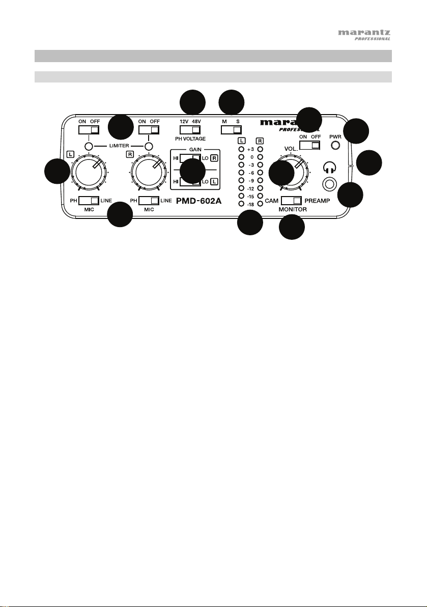
1. Limiter: Adjust these switches to turn the limiters On and Off. When the limiter is on, the
mic/line input gain will be automatically adjusted according to the set input level so that
distortion does not occur.
Note: If the input level is set too high, distortion may occur even when the limiter is on. If
this is the case, lower the input level or decrease the distance from the microphone and the
sound source.
2. Phantom Power Selector: When using condenser microphones, set the phantom power
switch to 12V or 48V accordingly.
3. Output Type: Adjust the switch to select Mono or Stereo for the type of signal that is
outputted.
4. Level Control: Adjust the rotary knobs to set the level for the XLR inputs.
5. Input Selector: Adjust the switch to select the input type: Line (for line-level sources), Mic
(for self-powered microphones), or PH (for microphones that require phantom power).
6. Gain Selector: Select low or high gain for the XLR inputs.
7. Level Indicator LED: View the input level LEDs in +3dB increments.
8. Headphone Level Control: Adjust the rotary knob to set the level of the headphone output.
9. Power ON/OFF Switch: Adjust this switch to turn the unit On and Off.
10. Power-ON Indicator: This LED will illuminate green when the unit is On.
11. 1/8” Headphone Output: Connect headphones to the 1/8” (3.5 mm) TRS output.
12. Output Selector Switch: Adjust this switch to send the audio to your DSLR camera
(PREAMP) or to listen to the audio signal from your DSLR camera (CAM).
13. Battery Compartment: Insert 4 AA batteries into this side compartment to power the unit.
10
11
13
3
Page 4

23
6
7
8
9
10
11
12
1
2
3
4
5
6
13
Connect this
1/8” (3.5 mm) TRS
MONITOR IN
LEFT RIGHT
output to the audio input of a DSLR
OUT
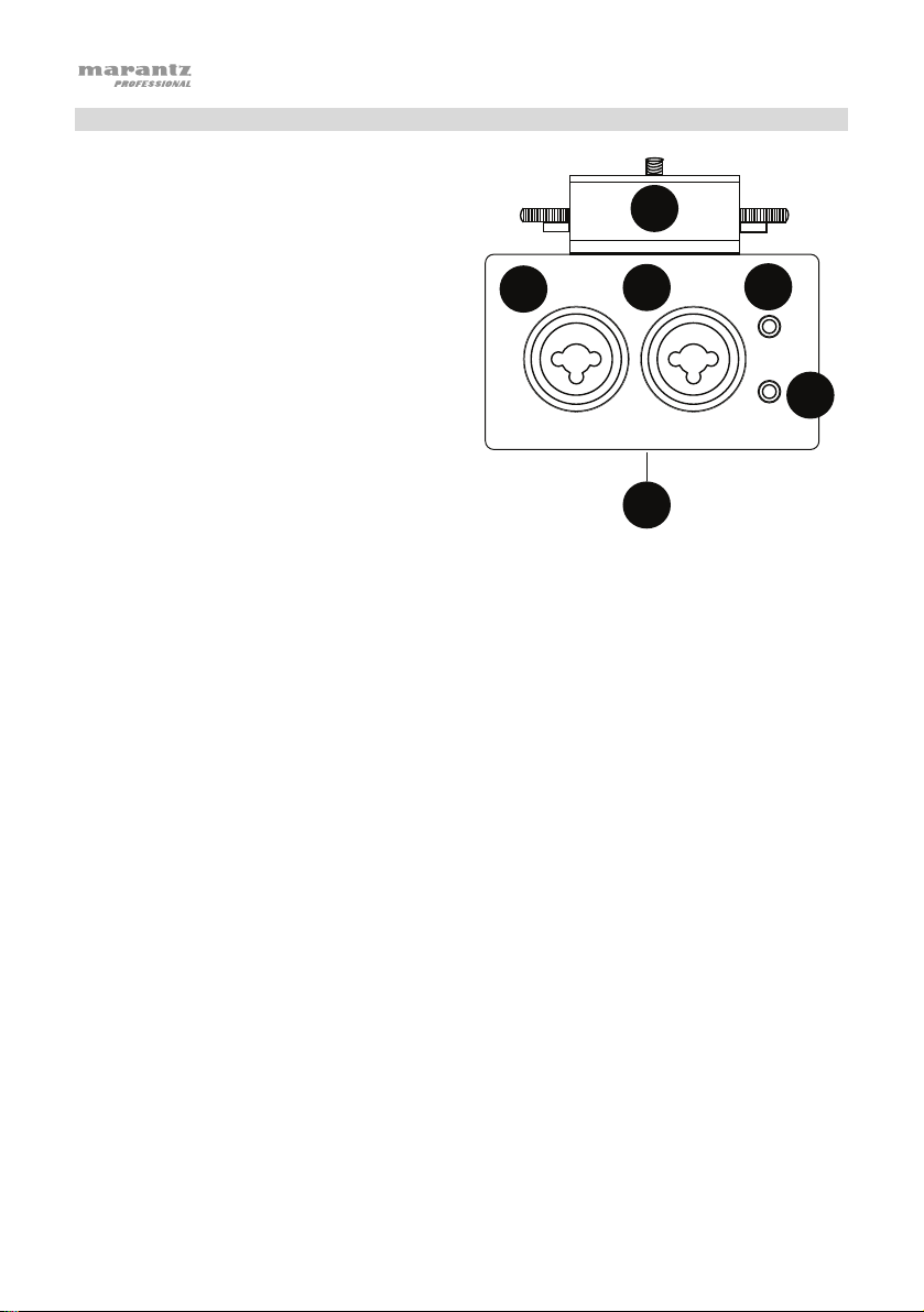
Rear Panel
1. XLR-1/4” TRS input: Connect a microphone
or line-level device to the XLR-1/4” (6.35 mm)
input.
2. XLR-1/4” TRS input: Connect a microphone
or line-level device to the XLR-1/4” (6.35 mm)
input.
Note: Ensure that phantom power is turned
off before connecting a line-level device to
the XLR-1/4” inputs. If you connect a linelevel device while phantom power is being
supplied, this can damage the device or this
unit.
Note: When using a condenser microphone,
before connecting to and disconnecting from
the XLR-1/4” inputs, ensure that phantom
power is turned off. If you connect or
disconnect a microphone while phantom
power is being supplied, this can damage the
unit or the microphone.
Note: Do not connect a dynamic microphone to an XLR-1/4” input when phantom power is
turned on. Doing so could damage the microphone or this unit.
3. 1/8” Input: Connect the audio output of a DSLR camera to this 1/8” (3.5 mm) TRS input.
4. 1/8” Output:
camera.
5. Hot Shoe Mount: Attach a DSLR camera on top of this hotshoe mount.
6. Threaded Insert: Connect your mounting adapter from a tripod, digital recorder, or lighting
panel here.
4
Page 5
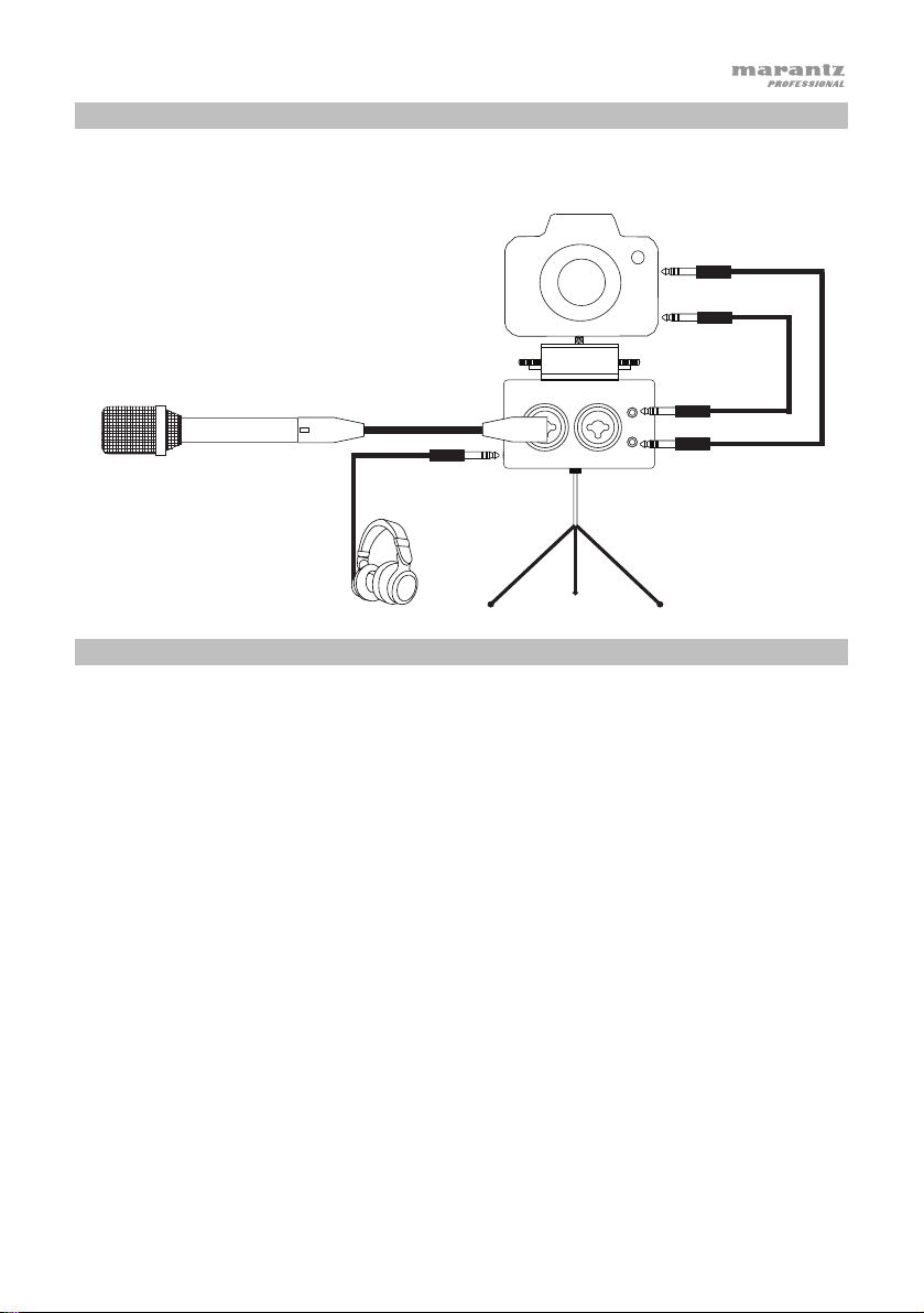
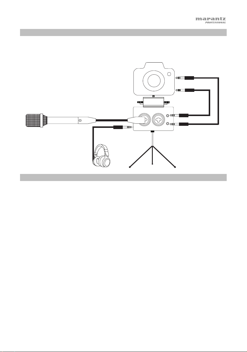
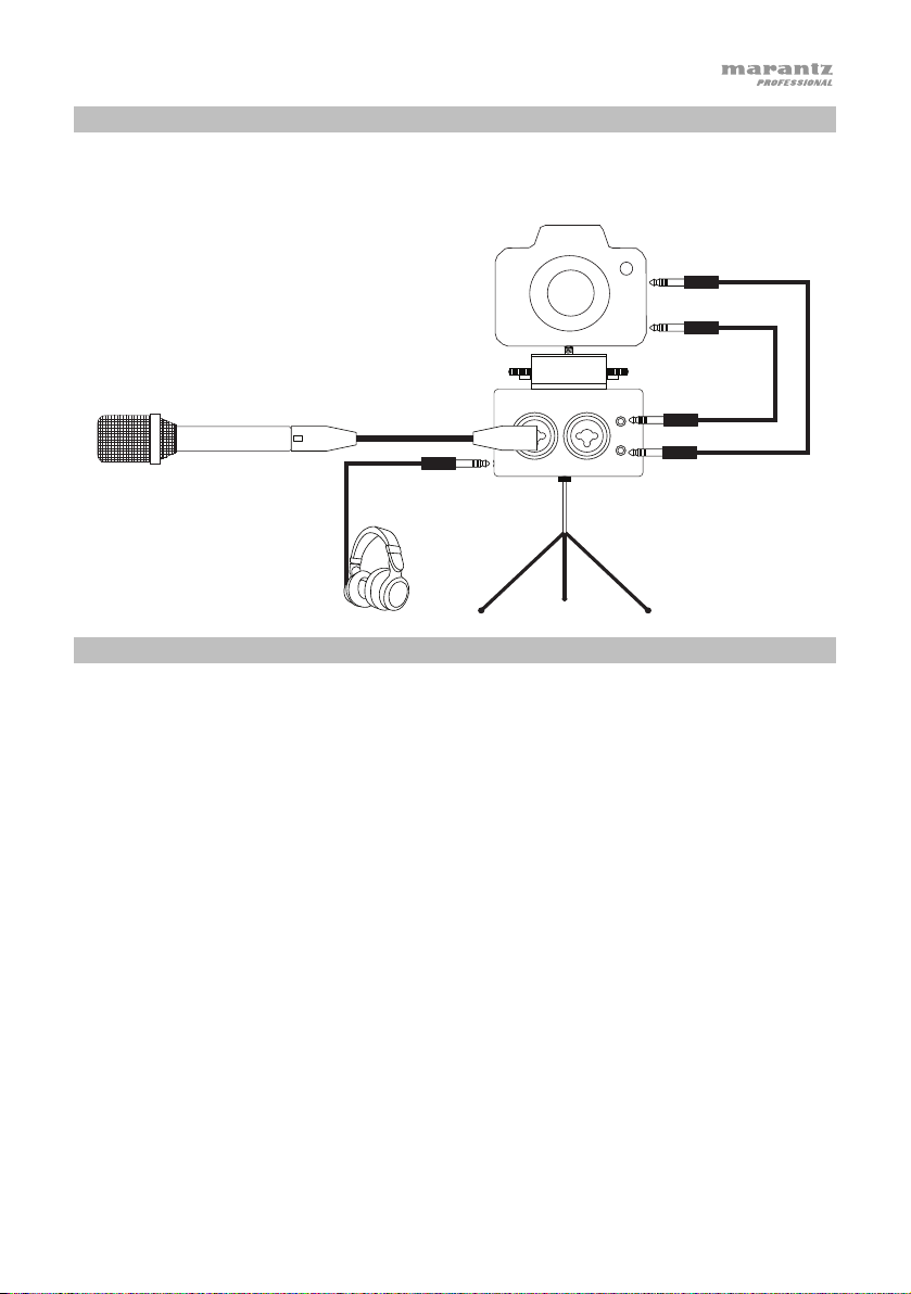
Setup
Items not listed under Introduction > Box Contents are sold separately.
Microphone
LEFT RIGHT
Tripod
Headphones
Operation
1. Attach your DSLR camera securely on top of the hot shoe mount.
2. Attach the Threaded Insert on PMD-602A onto your tripod mount.
3. Place the tripod on a level surface.
4. Connect microphones or line-level devices to PMD-602A and use the Input Selector to
choose Line (for line-level sources), Mic (for self-powered microphones), or PH (for
microphones that require phantom power).
5. If your microphone requires phantom power, select the appropriate voltage for your
microphone (12V or 48V) using the PH Voltage switch.
6. Adjust the Level control to set the gain for the input signal.
7. Set the Gain Selector for the channel to Hi (high) or Lo (low), depending on your source.
8. Use headphones to monitor the input signal or to hear the audio playback from your DSLR
camera.
Camera mic input
Camera audio
output
MONITORIN
OUT
5
Page 6

Guía del usuario (Español)
Introducción
Contenido de la caja
PMD-602A
Guía del usuario
Manual sobre la seguridad y garantía
Soporte
Para obtener la información más reciente acerca de este producto (documentación,
especificaciones técnicas, requisitos de sistema, información de compatibilidad, etc.) y
registrarlo, visite marantzpro.com.
Para obtener soporte adicional del producto, visite marantzpro.com/support.
6
Page 7
1
2 3
4
5
6
7
8
9
10
11
12
13
Características
Panel frontal
11
12
1. Limiter: Ajuste estos interruptores para encender y apagar el subwoofer. Cuando el
limitador se encuentra activado, la ganancia de la entrada micrófono/línea se ajusta
automáticamente en función del nivel de entrada ajustado de manera que no se produzcan
distorsiones.
Nota: Si el nivel de entrada se ajusta a un valor demasiado alto, pueden producirse
distorsiones por más que el limitador se encuentre activado. Si este es el caso, disminuya el
nivel de entrada o la distancia entre el micrófono en la fuente de sonido.
2. Selector de potencia fantasma: Al utilizar micrófonos condensadores, ajuste el interruptor
de potencia fantasma a 12 o 48 V según corresponda.
3. Tipo de salida: Ajuste el interruptor para seleccionar el tipo de señal monoaural o estéreo
que se emite por la salida.
4. Control del nivel: Ajuste las perillas giratorias para definir el nivel de las entradas XLR.
5. Selector de entrada: Ajuste el interruptor para seleccionar el tipo de entrada: Line (para
fuentes de nivel de línea), Mic (para micrófonos autoalimentados) o PH (para micrófonos
que requieran potencia fantasma).
6. Selector de ganancia: Seleccione una ganancia baja o alta para las entradas XLR.
7. LED indicador de nivel: Observe los LED del nivel de entrada en incrementos de +3dB.
8. Control del nivel del auricular: Ajuste las perillas giratorias para definir el nivel de la salida
para auriculares.
9. Interruptor de encendido/apagado: Utilice este interruptor para encender y apagar la
unidad.
10. Indicador de encendido: Este LED se ilumina de color verde cuando la unidad está
encendida.
11. Salida para auriculares de 1/8": Conecte auriculares a la salida TRS de 3,5 mm (1/8 pulg.).
12. Interruptor selector de salida: Ajuste este interruptor para enviar el audio a su cámara
DSLR (PREAMP) o para escuchar la señal de audio proveniente desde su cámara DSLR
(CAM).
13. Compartimiento para pilas: Inserte 4 pilas AA en este compartimento lateral para
alimentar la unidad.
10
13
7
Page 8
23
6
7
8
9
10
11
12
1
2
3
4
5
6
13
LEFT RIGHT
Conecte esta salida
TRS de 3,5 mm (1/8 pulg.)
a la entrada de audio
Panel trasero
1. Entrada XLR TRS de 1/4 pulg.: Conecte
un micrófono o dispositivo de nivel de
línea a la entrada XLR de 6,35 mm (1/4
pulg.).
2. Entrada XLR TRS de 1/4 pulg.: Conecte
un micrófono o dispositivo de nivel de
línea a la entrada XLR de 6,35 mm (1/4
pulg.).
Nota: Asegúrese de que la potencia
fantasma esté apagada antes de conectar
un dispositivo de nivel de línea a las
entradas XLR de 1/4 pulg. Si conecta un
dispositivo de nivel de línea mientras la
potencia fantasma está activada, pueden
producirse daños en el dispositivo o en
esta unidad.
Nota: Al usar utilizar un micrófono
condensador, antes de conectarlo o
desconectarlo de las entradas XLR de 1/4
pulg., asegúrese de que la potencia fantasma se encuentre apagada. Si conecta o
desconecta un micrófono mientras la potencia fantasma está activada, pueden producirse
daños en el micrófono o en esta unidad.
Nota: No conecte un micrófono dinámico a una entrada XLR de 1/4 pulg. cuando la
potencia fantasma se encuentre activada. Esto podría dañar el micrófono o esta unidad.
3. Entrada de 1/8 pulg.: Conecte la salida de audio de la cámara DSLR a esta entrada TRS de
3,5 mm (1/8 pulg.).
4. Salida de 1/8 pulg.:
de una cámara DSLR.
5. Zapata para cámara: Sujete una cámara DSLR en la parte superior de esta zapata para
cámara.
6. Punto de montaje roscado: Conecte aquí el adaptador de montaje de un trípode,
grabador digital o panel de iluminación.
8
MONITOR IN
OUT
Page 9
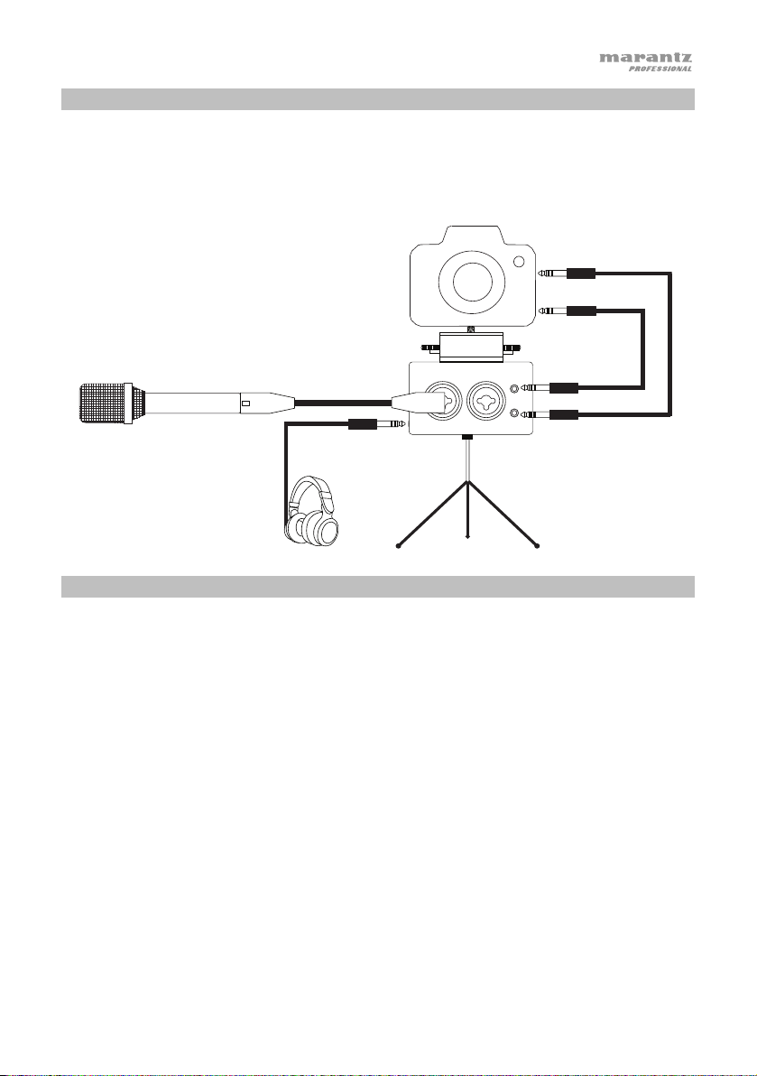
Instalación
Los elementos que no se enumeran en Introducción > Contenido de la caja se venden por
separado.
Micrófono
LEFT RIGHT
Trípode
Auriculares
Funcionamiento
1. Sujete su cámara DSLR con firmeza en la parte superior de la zapata.
2. Sujete el punto de montaje roscado del PMD-602A en su trípode.
3. Coloque el trípode sobre una superficie plana.
4. Conecte los micrófonos o dispositivos de nivel de línea al PMD-602A y utilice el selector de
entrada para seleccionar Line (para dispositivos de nivel línea), Mic (para micrófonos auto
alimentados) o PH (para micrófonos que requieran potencia fantasma).
5. Si su micrófono requiere potencia fantasma, seleccione el voltaje apropiado para su
micrófono (12 o 48 V) usando el interruptor PH Voltage.
6. Ajuste el control de nivel para ajustar la ganancia de la señal de entrada.
7. Ajuste el selector de ganancia para el canal en Hi (alto) o Lo (bajo), en función de su
fuente.
8. Utilice auriculares para monitorizar la señal de entrada o para escuchar la reproducción del
audio proveniente de su cámara DSLR.
Entrada para
micrófono de la
cámara
Salida
de audio de la
cámara
MONITORIN
OUT
9
Page 10

Guide d’utilisation (Français)
Présentation
Contenu de la boîte
PMD-602A
Guide d'utilisation
Consignes de sécurité et informations concernant la garantie
Assistance technique
Pour les toutes dernières informations concernant la documentation, les spécifications
techniques, la configuration requise, la compatibilité et l’enregistrement du produit, veuillez
visiter marantzpro.com.
Pour de l’assistance supplémentaire, veuillez visiter le site marantzpro.com/support.
10
Page 11

1
2 3
4
5
6
7
8
9
10
11
12
13
Caractéristiques
Panneau avant
10
13
11
12
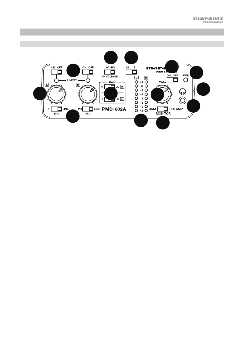
1. Limiter : Ces sélecteurs permettent d’activer (On) et désactiver (Off) les limiteurs. Lorsque
le limiteur est activé, le gain de l’entrée mic/line sera automatiquement ajusté selon le
niveau d’entrée afin d’éviter toute distorsion.
Remarque : Si le niveau d'entrée est trop élevé, de la distorsion peut se produire même
lorsque le limiteur est activé. Si c’est le cas, réduisez le niveau d’entrée ou la distance entre
le microphone et la source audio.
2. Sélecteur d’alimentation fantôme : Lors de l’utilisation de microphones à condensateur,
ce sélecteur permet de régler l’alimentation fantôme selon l’alimentation requise : 12 V ou
48 V.
3. Type de signal de sortie : Ce sélecteur permet de régler le type de signal de sortie : Mono
ou Stereo.
4. Commande de niveau : Ces boutons rotatifs permettent de régler le niveau des entrées
XLR.
5. Sélecteur d'entrée : Ce sélecteur permet de régler le type de signal d’entrée : Line (pour
les sources à niveau ligne), Mic (pour les microphones autonomes) ou PH (pour les
microphones qui nécessitent une alimentation fantôme).
6. Sélecteur de gain : Ces sélecteurs permettent de régler le niveau de gain des entrées XLR.
7. Indicateurs de niveau : Ces DEL permettent de visualiser le niveau d'entrée par incréments
de +3 dB.
8. Commande de niveau du casque : Ce bouton rotatif permet de régler le niveau de la sortie
casque.
9. Interrupteur d’alimentation : Cet interrupteur permet de mettre l’appareil sous tension (On)
et hors tension (Off).
10. Voyant d’alimentation : Ce voyant DEL devient vert lorsque l’appareil est sous tension
(On).
11. Sortie casque 3,5 mm : Cette sortie permet de brancher un casque d’écoute TRS 3,5 mm.
12. Sélecteur de sortie : Ce sélecteur permet d’envoyer le signal audio à un appareil-photo
reflex numérique (PREAMP) ou d’écouter le signal audio via un appareil-photo reflex
numérique (CAM).
13. Compartiment des piles : Ce compartiment latéral permet d’insérer 4 piles de types AA
afin d’alimenter l’appareil.
11
Page 12

23
6
7
8
9
10
11
12
1
2
3
4
5
6
13
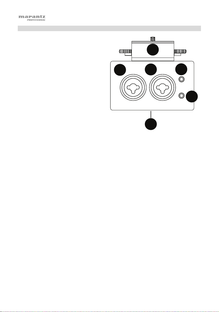
Panneau arrière
1. Entrée TRS XLR-6,35 mm : Cette entrée
permet de brancher un microphone ou un
appareil à niveau ligne.
2. Entrée TRS XLR-6,35 mm : Cette entrée
permet de brancher un microphone ou un
appareil à niveau ligne.
Remarque : Veillez à ce que l’alimentation
fantôme soit désactivée avant de brancher
un appareil à niveau ligne aux entrées XLR6,35 mm. Si vous branchez un appareil à
niveau ligne alors que l’alimentation
fantôme est activée, ceci pourrait
endommager l’autre appareil ou celui-ci.
Remarque : Avant de brancher ou de
débrancher un microphone à condensateur
de l’une des entrées XLR-6,35 mm, veillez
à ce que l’alimentation fantôme soit
désactivée. Si vous branchez ou
débranchez un microphone alors que
l’alimentation fantôme est activée, ceci pourrait endommager cet appareil ou le microphone.
Remarque : Ne pas branchez un microphone électrodynamique à l’une des entrées XLR6,35 mm lorsque l’alimentation fantôme est activée. Cela pourrait endommager le
microphone ou cet appareil.
3. Entrée 3,5 mm : Cette entrée TRS 3,5 mm permet de brancher un appareil-photo reflex
numérique.
4. Sortie 3,5 mm :
appareil-
5. Sabot pour griffe standard d’appareil-photo : Ce sabot permet de fixer un appareil-
photo.
6. Embase filetée : Cette embase permet de fixer un adaptateur pour un trépied, un
enregistreur numérique ou panneau d’éclairage.
12
photo reflex numérique.
Cette sortie TRS 3,5 mm peut être branchée à l’entrée audio d’un
LEFT RIGHT
MONITOR IN
OUT
Page 13
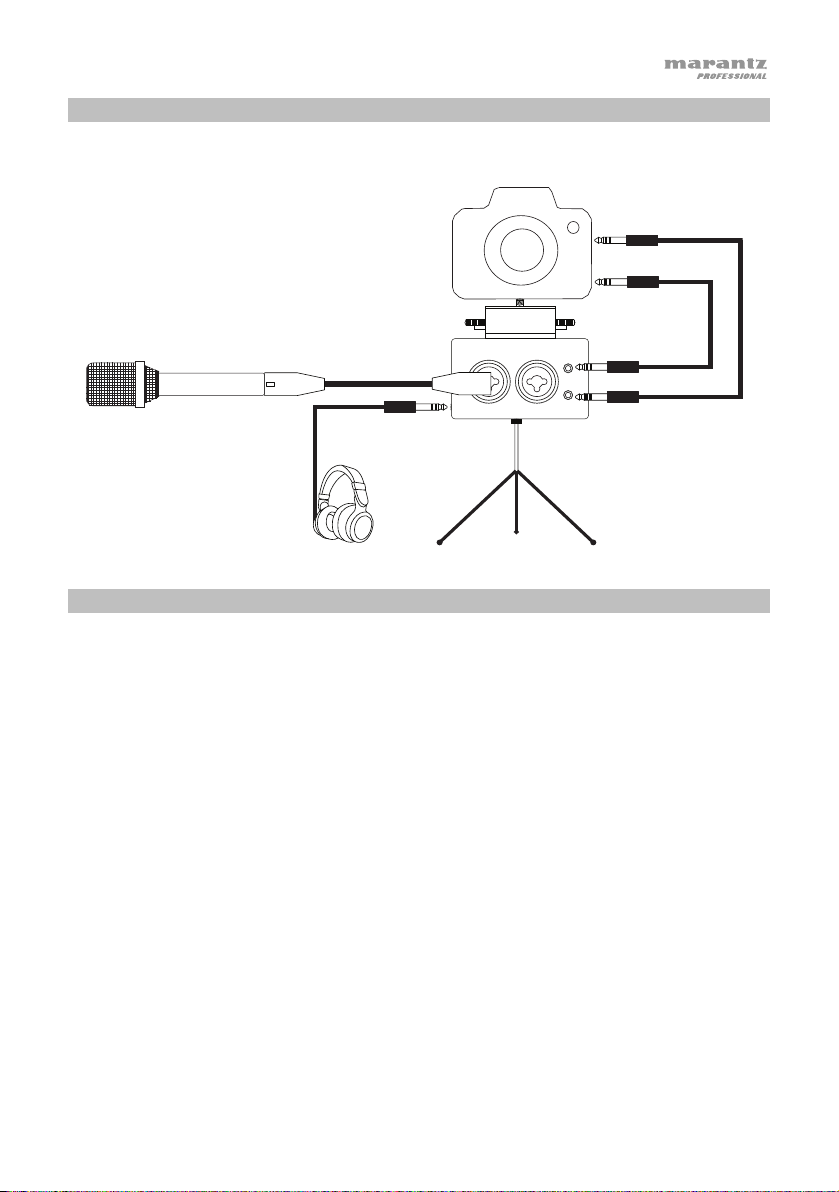
Installation
Les articles qui ne figurent pas dans la section Présentation > Contenu de la boîte sont vendus
séparément.
Fonctionnement
Microphone
Casque
d’écoute
LEFT RIGHT
Trépied
1. Fixez l’appareil-photo reflex numérique sur le sabot de la griffe.
2. Visez l’embase filetée du PMD-602A sur la fixation du trépied.
3. Placez le trépied sur une surface au niveau.
4. Branchez les microphones ou appareils à niveau ligne au PMD-602A et réglez le sélecteur
d’entrée sur Line (pour les sources à niveau ligne), Mic (pour les microphones autonomes)
ou PH (pour les microphones qui nécessitent une alimentation fantôme).
5. Si le microphone nécessite une alimentation fantôme, sélectionnez la tension appropriée
pour le microphone (12 V ou 48 V) en utilisant le sélecteur de tension PH Voltage.
6. Utilisez la commande de niveau afin de régler le gain du signal d’entrée.
7. Réglez le sélecteur de gain pour le canal sur élevé (Hi) ou faible (Lo), selon la source audio.
8. Utilisez un casque d’écoute pour surveiller le signal d’entrée ou pour écouter le signal audio
depuis un appareil-photo reflex numérique.
Entrée microphone
de l’appareil-photo
Sortie audio de
l’appareil-photo
MONITORIN
OUT
13
Page 14

Guida per l'uso (Italiano)
Introduzione
Contenuti della confezione
PMD-602A
Guida per l'uso
Istruzioni di sicurezza e garanzia
Assistenza
Per le ultime informazioni in merito a questo prodotto (documentazione, specifiche tecniche,
requisiti di sistema, informazioni sulla compatibilità, ecc.) e per effettuarne la registrazione,
recarsi alla pagina marantzpro.com.
Per ulteriore assistenza sul prodotto, recarsi alla pagina marantzpro.com/support.
14
Page 15

1
2 3
4
5
6
7
8
9
10
11
12
13
Caratteristiche
Pannello anteriore
11
12
1. Limiter: servirsi di questi interruttori per accendere (On) e spegnere (Off) i limitatori. Quando
il limitatore è acceso, il guadagno di ingresso mic/linea sarà regolato automaticamente in
base al livello di ingresso impostato, in modo che non si verifichi alcuna distorsione.
Nota bene: se il livello di ingresso è troppo elevato, si può verificare distorsione anche
quando il limitatore è acceso. In questo caso, abbassare il volume di ingresso o ridurre la
distanza fra il microfono e la fonte audio.
2. Selettore alimentazione Phantom: quando si utilizzano microfoni a condensatore,
posizionare l’interruttore dell’alimentazione phantom su 12V o 48V, a seconda dei casi.
3. Tipo di uscita: regolare l’interruttore per selezionare Mono o Stereo per il tipo di segnale
emesso.
4. Controllo di livello: regolare le manopole per impostare il livello degli ingressi XLR.
5. Selettore di ingressi: regolare l’interruttore per selezionare il tipo di ingresso: Line (per fonti
a livello di linea), Mic (per microfoni ad alimentazione autonoma), o PH (per microfoni che
richiedono alimentazione phantom).
6. Selettore Gain (guadagno): selezionare il livello di guadagno basso o elevato per gli
ingressi XLR.
7. LED indicatore di livello: visualizzazione LED livello di ingresso in incrementi di +3dB.
8. Comando Headphone Level (livello cuffia): regolare la manopola per impostare il livello
dell’uscita cuffie.
9. Interruttore ON/OFF (accensione/spegnimento): servirsi di questi interruttori per
accendere (On) e spegnere (Off) l’apparecchio.
10. Indicatore di alimentazione (ON): questo LED si illumina quando l'apparecchio è acceso
(On).
11. Uscita cuffie da 1/8”: collegare le cuffie all’uscita TRS da 1/8” (3,5 mm).
12. Interruttore selettore di uscita: regolare questo interruttore per inviare l’audio alla
videocamera DSLR (PREAMP) o per ascoltare il segnale audio della videocamera DSLR
(CAM).
13. Scomparto batterie: inserire 4 batterie AA in questo scomparto laterale per accendere
l’apparecchio.
10
13
15
Page 16

23
6
7
8
9
10
11
12
1
2
3
4
5
6
13
collegare questa uscita
TRS da 1/8” (3,5 mm)
LEFT RIGHT
all’ingresso audio di una
Pannello posteriore
1. Ingresso TRS XLR-1/4" collegare un
microfono o un dispositivo a livello di linea
all’ingresso XLR-1/4” (6,35 mm).
2. Ingresso TRS XLR-1/4" collegare un
microfono o un dispositivo a livello di linea
all’ingresso XLR-1/4” (6,35 mm).
Nota bene: assicurarsi che l’alimentazione
phantom sia spenta prima di collegare un
dispositivo a livello di linea agli ingressi
XLR-1/4”. Se si collega un dispositivo a
livello di linea quando l'alimentazione
phantom è accesa, è possibile danneggiare
l’apparecchio o il microfono.
Nota bene: quando si utilizza un microfono
a condensatore, prima di collegarlo e
scollegarlo dagli ingressi XLR-1/4”,
assicurarsi che l’alimentazione phantom sia
spenta. Se si collega o si scollega un
microfono quando l'alimentazione phantom è accesa, è possibile danneggiare l’apparecchio
o il microfono.
Nota bene: non collegare un microfono dinamico a un ingresso XLR-1/4” quando
l’alimentazione phantom è accesa. Ciò potrebbe danneggiare il microfono o l’apparecchio.
3. Ingresso da 1/8”: collegare l’uscita audio di una videocamera DSLR a questo ingresso TRS
da 1/8” (3,5 mm).
4. Uscita da 1/8”:
videocamera DSLR.
5. Base di supporto hot shoe: fissare una videocamera DSLR a questa base di supporto hot
shoe.
6. Inserto filettato: collegare a questo livello l’adattatore di montaggio di un treppiede, un
registratore digitale o un pannello di illuminazione.
16
MONITOR IN
OUT
Page 17
Configurazione
Elementi non elencati sotto Introduzione > Contenuti della confezione sono venduti
separatamente.
Microfono
LEFT RIGHT
Treppiede
Cuffie
Uso
1. Fissare con cura la videocamera DSLR alla base di supporto hot shoe.
2. Fissare l’inserto filettato del PMD-602A sul treppiede.
3. Collocare il treppiede su una superficie uniforme.
4. Collegare microfoni o dispositivi a livello di linea al PMD-602A e servirsi del Selettore di
ingressi per scegliere Line (per fonti a livello di linea), Mic (per microfoni dall’alimentazione
indipendente) o PH (per microfoni che richiedono alimentazione phantom).
5. Se il proprio microfono richiede alimentazione phantom, selezionare la tensione adeguata
(12V o 48V) servendosi dell’interruttore PH Voltage.
6. Regolare il comando Level per impostare il guadagno del segnale di ingresso.
7. Impostare il Selettore di guadagno del canale su Hi (alto) o Lo (basso), a seconda della
fonte.
8. Servirsi di cuffie per monitorare il segnale di ingresso o per ascoltare la riproduzione
dell’audio dalla propria videocamera DSLR.
Ingresso mic
videocamera
Audio
videocamera
Uscita
MONITORIN
OUT
17
Page 18

Benutzerhandbuch (Deutsch)
Einführung
Lieferumfang
PMD-602A
Benutzerhandbuch
Sicherheitshinweise und Garantieinformationen
Kundendienst
Für die neuesten Informationen zu diesem Produkt (Dokumentation, technische Daten,
Systemanforderungen, Informationen zur Kompatibilität etc.) und zur Produktregistrierung
besuchen Sie marantzpro.com.
Für zusätzlichen Produkt-Support besuchen Sie marantzpro.com/support.
18
Page 19

1
2 3
4
5
6
7
8
9
10
11
12
13
Funktionen
Vorderseite
12
1. Limiter: Stellen Sie diese Schalter ein, um die Limiter ein- und auszuschalten. Wenn der
Limiter eingeschaltet ist, wird der Verstärkungsfaktor automatisch auf den eingestellten
Eingangspegel angepasst, so dass keine Verzerrungen auftreten.
Hinweis: Wenn der Eingangspegel zu hoch eingestellt ist, kann es auch dann zu
Verzerrungen kommen, wenn der Limiter eingeschaltet ist. Wenn dies der Fall ist, verringern
Sie den Eingangspegel oder den Abstand vom Mikrofon und der Schallquelle.
2. Schalter Phantomspeisung: Bei der Verwendung von Kondensatormikrofonen, stellen Sie
den Phantomspeisungsschalter entweder auf 12V oder 48V.
3. Ausgangstyp: Stellen Sie den Schalter ein, um Mono oder Stereo für die Art des Signals
auszuwählen, das ausgegeben wird.
4. Verstärkung: Stellen Sie mit den Drehreglern den Pegel für die XLR-Eingänge ein.
5. Eingangswahlschalter: Stellen Sie mit dem Schalter den Eingangstyp ein: Line (für LineLevel-Quellen), Mic (für batteriebetriebene Mikrofone) oder PH (für Mikrofone mit
Phantomspeisung).
6. Gain-Wahlschalter: Wählen Sie eine niedrige oder hohe Verstärkung für die XLR-Eingänge.
7. LED-Pegelanzeige: Zeigt die Eingangspegel-LEDs in + 3dB-Schritten an.
8. Kopfhörer-Lautstärkeregelung: Stellen Sie mit dem Drehregler den Pegel des
Kopfhörerausgangs ein.
9. Ein-/Ausschalter: Stellen Sie diesen Schalter ein, um das Gerät ein- und auszuschalten.
10. Netzanzeige: Diese LED leuchtet grün, wenn das Gerät eingeschaltet ist.
11. 1/8"-Kopfhörerausgang: Schließen Sie Kopfhörer an den 1/8" (3,5 mm) TRS-Ausgang an.
12. Ausgangswahlschalter: Stellen Sie diesen Schalter ein, um das Audiomaterial an Ihre
13. Batteriefach: Legen Sie 4 AA-Batterien in dieses Seitenfach ein, um das Gerät mit Strom zu
DSLR-Kamera (PREAMP) zu senden oder um das Audiosignal Ihrer DSLR-Kamera
abzuspielen (CAM).
versorgen.
10
11
13
19
Page 20
23
6
7
8
9
10
11
12
1
2
3
4
5
6
13
LEFT RIGHT
Rückseite
1. XLR-1/4" TRS-Eingang: Schließen Sie
ein Mikrofon oder Line-Gerät an diesen
XLR-1/4" (6,35 mm) Eingang an.
2. XLR-1/4" TRS-Eingang: Schließen Sie
ein Mikrofon oder Line-Gerät an diesen
XLR-1/4" (6,35 mm) Eingang an.
Hinweis: Stellen Sie sicher, dass die
Phantomspeisung ausgeschaltet ist,
bevor Sie ein Line-Level-Gerät an die
XLR-1/4" Eingänge anschließen. Wenn
Sie ein Line-Level-Gerät anschließen,
während die Phantomspeisung aktiv ist,
kann dies das Gerät oder diese Einheit
beschädigen.
Hinweis: Stellen Sie bei Verwendung
eines Kondensatormikrofons vor dem
Anschließen an und dem Trennen von
den XLR-1/4" Eingängen sicher, dass
die Phantomspeisung ausgeschaltet ist.
Wenn Sie ein Mikrofon anschließen oder
trennen, während die Phantomspeisung
aktiv ist, kann dies das Gerät oder das
Mikrofon beschädigen.
Hinweis: Schließen Sie kein dynamisches Mikrofon an einen XLR-1/4"-Eingang an, wenn
die Phantomspeisung eingeschaltet ist. Andernfalls könnte das Mikrofon oder dieses Gerät
beschädigt werden.
3. 1/8" Eingang: Schließen Sie den Audioausgang einer DSLR-Kamera an diesen 1/8" (3,5
mm) TRS Eingang an.
4. 1/8" Ausgang: Schließen Sie den Audioeingang einer DSLR-Kamera an diesen 1/8" (3,5
mm) TRS Ausgang an.
5. Blitzschuh-Anschluss: Befestigen Sie eine DSLR-Kamera auf diesem BlitzschuhAnschluss.
6. Gewindeeinsatz: Schließen Sie hier den Montageadapter eines Stativs, Digitalrekorders
oder Leuchtfeldes an.
20
MONITOR IN
OUT
Page 21
Setup
Teile, die nicht unter Einführung > Lieferumfang angegeben sind, sind separat erhältlich.
Mikrofon
LEFT RIGHT
Stativ
Kopfhörer
Betrieb
1. Befestigen Sie Ihre DSLR-Kamera sicher am Blitzschuh-Anschluss.
2. Befestigen Sie den Gewindeeinsatz des PMD-602A auf Ihrer Stativhalterung.
3. Stellen Sie das Stativ auf eine ebene Fläche.
4. Schließen Sie Mikrofone oder Line-Level-Geräte an das PMD-602A an und verwenden Sie
den Eingangswahlschalter, um Line (für Line-Level-Quellen), Mic (für batteriebetriebene
Mikrofone) oder PH (für Mikrofone mit Phantomspeisung) zu wählen.
5. Wenn Ihr Mikrofon Phantomspeisung erfordert, wählen Sie die entsprechende Spannung für
Ihr Mikrofon (12V oder 48V) mit dem PH-Spannungsschalter.
6. Stellen Sie den Pegelregler ein, um die Verstärkung für das Eingangssignal einzustellen.
7. Stellen Sie den Gain-Wahlschalter für den Kanal je nach Quelle auf Hi (high) oder Lo (low)
ein.
8. Verwenden Sie Kopfhörer, um das Eingangssignal zu überwachen oder die
Audiowiedergabe von Ihrer DSLR-Kamera zu hören.
Kameramikrofoneingang
Kamera-
Audioausgang
MONITORIN
OUT
21
Page 22

Appendix (English)
Technical Specifications
Power Requirement
Battery Life
Power Consumption
Operating Temperature
Operating Humidity
Frequency Response
Signal-to-Noise Ratio
Max Mic Input Level
Mic Input Sensitivity
Mic Input Impedance
Max Line Input Level
Line Input Impedance
Connectors
Phantom Power
Maximum Voltage Gain
Dimensions
(width x depth x height)
Weight
Specifications are subject to change without notice.
Trademarks & Licenses
Marantz is a trademark of D&M Holdings Inc., registered in the U.S. and other countries. Marantz Professional
products are produced by inMusic Brands, Inc., Cumberland, RI 02864, USA.
All other product names, company names, trademarks, or trade names are those of their respective owners.
22
4 AA batteries
15 hours (with phantom power off)
12 hours (with phantom power on)
< 5 W
41–140°F / 5–60°C
25–85%, non-condensing
20 Hz–20 kHz, +1 dB
> 94 dB
-20 dBu (high gain), +10 dB (low gain)
-40 dBu
2 kΩ
+24 dB
10 kΩ
(2) XLR-1/4" (6.35 mm) TRS stereo inputs
(1) 1/8" (3.5 mm) TRS stereo output
(1) 1/8" (3.5 mm) stereo headphone output
12V and 48V (switchable)
-24 dB
2.5" x 6.0" x 1.5"
64 x 152 x 38 mm
1.40 lbs.
0.63 kg
Page 23

23
Page 24

marantzpro.com
Manual Version 1.3
 Loading...