

Page 1
.-
......
_-.®
Model ZS5300 User Guide
Multi Zone Selector
Page 2
CAUTION
RISK
CAUTION: TO REDUCE THE RISK OF ELECTRIC SHOCK,
DO NOT REMOVE COVER (OR BACK)
NO USER-SERVICEABLE PARTS INSIDE
REFER SERVICING TO QUALIFIED SERVICE PERSONNEL
The lightning flash with arrowhead symbol withinanequilateral
triangle is intended to alert the user to the presence of
uninsulated "dangerous voltage" within the product's enclosure
that may be of sufficient magnitude to constitute a risk of
electric shock to persons.
The exclamation point within
to alert the user to the presence of important operating and
maintenance
accompanying
OF
ELECTRIC SHOCK
DO
NOT OPEN
an
(servicing)
the
product.
instructionsinthe
equilateral triangleisintended
literature
WARNING
TO
REDUCE
PRODUCTTORAINORMOISTURE.
CAUTION:
ATTENTION:
NOTE TO CATV SYSTEM INSTALLER:
This reminder is provided to call the CATV (Cable-TV) system installer's attention to Section 820-40 of the NEC which
provides guidelines for proper grounding and,
grounding system of the building, as close to the point of cable entry as practical.
THE
RISKOFFIREORELECTRIC
TO
PREVENT
WIDE
SLOT,
POUR
PLUS
LA
PRISEETPOUSSER
ELECTRIC
FULLY
EVITER
INSERT.
LES
LARGEDELA
in
particular, specifies that the cable ground shall be connected to the
SHOCK,DONOT
SHOCK,
CHOCS
FICHE
ELECTRIQUES,
DANSLABORNE
JUSQU'AUFOND.
MATCH
WIDE
EXPOSE
BLADEOFPLUG
THIS
INTRODUIRELALAME
CORRESPONDANTE
TO
LA
DE
Page 3

IMPORTANT SAFETY
INSTRUCTIONS
READ BEFORE OPERATING EQUIPMENT
This product was designed and manufactured to meet strict
quality and safety standards. There are, however, some
installation and operation precautions which you should
particularly aware of.
1. Read Instructions -
be
should
Retain Instructions - The safety and operating instructions
2.
read
All
the safety
and
operating instructions
before the product is operated.
should be retained for future reference.
3.
Heed Warnings - All warnings
operating instructions should
4.
Follow Instructions - All operating and use instructions
on
the product andinthe
be
adhered to.
should be followed.
5.
Cleaning - Unplug this product from the wall outlet before
cleaning.
Do
not use liquid cleaners or aerosol cleaners.
Use a damp cloth for cleaning.
Attachments -
6.
Do
not use attachments not recommended
by the product manufacturer as they may cause hazards.
Water and Moisture -
7.
Do
not use this product near water-
for example, near a bath tub, wash bowl, kitchen sink, or
in
laundry tub,
a wet basement, or near a swimming pool,
and the like.
8.
Accessories -
Do
not place this productonan
cart, stand, tripod, bracket, or table. The product may fall,
causing serious injury to a child or adult, and serious
damage to the product. Use only with a cart, stand, tripod,
bracket, or table recommended by the manufacturer, or
sold with the product. Any mounting of the product should
follow the manufacturer's instructions, and should use a
mounting accessory recommended by the manufacturer.
9. A product and cart combination should be
moved with care. Quick stops, excessive
force, and uneven surfaces may cause the
to
product and cart combination
10.Ventilatlon - Slots
for ventilation and
and
openingsinthe cabinet are provided
to
ensure reliable operation of the product
and to protect it from overheating,
overturn.
and
these openings must
not be blocked or covered. The openings should never
blockedbyplacing the productona
similar surface. This product should not
bed,
sofa,
be
placedina built-in
installation such as a bookcase or rack unless proper
ventilation is provided or the manufacturer's instructions
have been adhered
to.
11.Power Sources - This product should be operated only
on
from the type of power source indicated
If
you are not sure of the type of power supplytoyour home,
the marking label.
consult your product dealer or local power company. For
products intended to operate from battery power, or other
to
sources, refer
12.Grounding
the operating instructions.
or
Polarization
-
This
product
equipped with a polarized alternating-current line plug (a
plug having one blade wider than the other). This plug will fit
into the power outlet only one way. This is a safety feature.
If
you are unable to insert the plug fully into the outlet, try
reversing the plug.
If
the plug should still fail to
your electrician to replace your obsolete outlet. Do not
defeat the safety purpose of the polarized plug.
rug,
fit,
be
unstable
be
or other
may be
contact
13.Power-Cord Protection - Power-supply cords should be
so
routed
that they are not likely to be walkedonor pinched
by items placed upon or against them, paying particular
to
attention
cords at plugs, convenience receptacles, and
the point where they exit from the product.
14.Protective Attachment Plug - The product is eqUipped
an
with
attachment plug having overload protection. This is
a safety feature. See Instruction Manual for replacement or
If
resetting of protective device.
required,besure
the
service
replacement of the plug is
technician
has
used a
replacement plug specified by the manufacturer that has
the same overload protection as the original plug.
15.0utdoor Antenna Grounding -
Ifanoutside antenna or
cable system is connected to the product, be sure the
antenna or cable system is grounded so as to provide
some protection against voltage surges and built-up static
the
charges. Article 810 of
National Electrical Code,
ANSI/NFPA 70, provides information with regard to proper
grounding of the mast and supporting structure, grounding
an
of the lead-in wire to
antenna discharge unit, size of
grounding conductors, location of antenna-discharge unit,
connection to grounding electrodes, and requirements for
the grounding electrode. See Figure
1.
Figure 1
EXAMPLE OF ANTENNA GROUNDING AS PER
NATIONAL ELECTRICAL CODE, ANSIINFPA 70
ANTENNA
LEAD
IN
WIRE
GROUND CLAMPS
This Class Bdigital apparatus complies with Cet appareil numerique
Canadian ICES-003. conforme ala norme NMB-003 du Canada.
'-:::'~Ofi":
NEC - NATIONAL ELECTRICAL CODE
....
___
~
POWER SERVICE GROUNDING
ELECTRODE SYSTEM (NEC
ART 250, PART H)
de la Classe
Best
Page 4
16.Lightning lightning storm, or when
For
added protection for this product during a
it
is left unattended
and
unused for
long periods of time, unplug it from the wall outlet and
disconnect the antenna or cable system. This will prevent
damage to the product due to lightning and power-line
surges.
17.Power Lines -
outside antenna system should not
be
An
locatedinthe vicinity of overhead power lines or other
can
electric light or power circuits, or where it
power lines or circuits. When installing
fall into such
an
outside antenna
system, extreme care should be taken to keep from
touching such power lines or circuits as contact with them
be
might
18.0verloading-Do
fatal.
not overload wall outlets, extension
cords, or integral convenience receptacles as this can
in
result
19.0bject
a risk of fire or electric shock.
and
liqUid
Entry - Never
push
objects of
any
kind
into this product through openings as they may touch
dangerous voltage points or short-out parts that could result
in
a fire or electric shock. Never spill liquidofany
kindonthe
product.
Do
20.Servicing openingorremoving
as
not attempt to service this product yourself
covers
may
expose
you to
dangerous voltage or other hazards. Refer all servicing
qualified service personnel.
21.Damage Requiring Service - Unplug this product from
the wall outlet and refer servicing to qualified service
personnel under the following conditions:
a.
When the power-supply cord or plugisdamaged.
b. If liquid has been spilled, or objects have fallen into the
product.
If
the product has been exposedtorain
c.
If
the product does not operate normally by following the
d.
operating instructions. Adjust only those controls that
or water.
are
covered by the operating instructions asanimproper
may
adjustment of other controls
often require extensive work
resultindamage and will
by
a qualified technician to
restore the product to its normal operation.
If
the
e.
product
has
been
dropped or damagedinany
way,
and
f. When the product exhibits a distinct changeinperformance
- this indicates a need for service.
22.Replacement
required,
replacement parts specified
be
Parts
sure
- When
the
service
by
technician
the manufacturer or have the
replacement
parts
has
are
used
same characteristics as the original part. Unauthorized
in
substitutions may result
fire, electric shock, or other
.hazards.
23.Safety Check - Upon completion of any service or repairs
to
this product, ask the service techniciantoperform safety
checks to determine that the product is
in
proper operating
condition.
The
24.Wall or Ceiling Mounting -
toawallorceiling
onlyasrecommendedbythe manufacturer.
25.Heat - The product should
as
sources such
radiators, heat registers, stoves, or other
product shouldbemounted
be
situated away from heat
products (including amplifiers) that produce heat.
be
26.Apparatus shall not
exposedtodripping and splashing
andnoobjects filled with liquids, suchasvases, shall be
on
placed
the apparatus.
to
Page 5
Table
of
Contents
Introduction
Features 2
About the keypad 3
Accessories 3
Functional Overview 4
Front panel 4
Rear panel 5
Remote control unit (RC5300ZS) 6
ID
Code Setup 8
Preparation
Connecting speakers 9
Connection example 10
Operation Examples...................••.•.....•.........15
Remote Code List
Troubleshooting
Care
and
Specification 18
and
Connection 9
Maintenance
16
17
17
2
1
Page 6
Introduction
Features
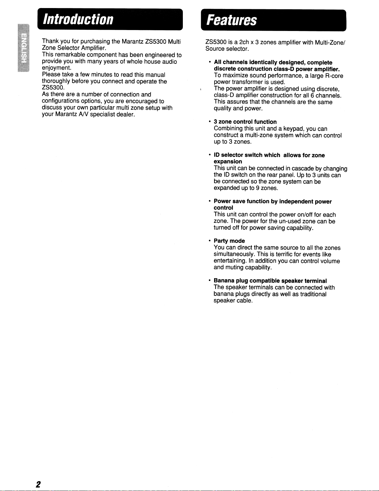
Thank you for purchasing the Marantz ZS5300 Multi
Zone Selector Amplifier.
This remarkable component has been engineered to
provide you with many years of whole house audio
enjoyment.
Please take a few minutes to read this manual
thoroughly before you connect and operate the
ZS5300.
As there are a number of connection and
configurations options, you are encouraged to
discuss your own particular multi zone setup with
your Marantz
AN
specialist dealer.
ZS5300 is a 2ch x 3 zones amplifier with Multi-Zonel
Source selector.
• All channels identically designed, complete
discrete construction class-O power amplifier.
To maximize sound performance, a large R-core
power transformer is used.
The power amplifier
c1ass-D
This assures that the channels are the same
quality and power.
• 3 zone control function
Combining this unit and a keypad, you can
construct a multi-zone system which can control
up to 3 zones.
•10selector switch which allows for zone
expansion
This unit can be connectedincascade by changing
the
be connected so the zone system can be
expanded up to 9 zones.
• Power save function by independent power
control
This unit can control the power onloff for each
zone. The power for the un-used zone can be
turned off for power saving capability.
amplifier construction for all 6 channels.
ID
switch on the rear panel. Up to 3 units can
is
designed using discrete,
• Party mode
You can direct the same source to all the zones
simultaneously. This is terrific for events like
entertaining.
and muting capability.
• Banana plug compatible speaker terminal
The speaker terminals can be connected with
banana plugs directly as well as traditional
speaker cable.
In
addition you can control volume
2
Page 7
IAbout.
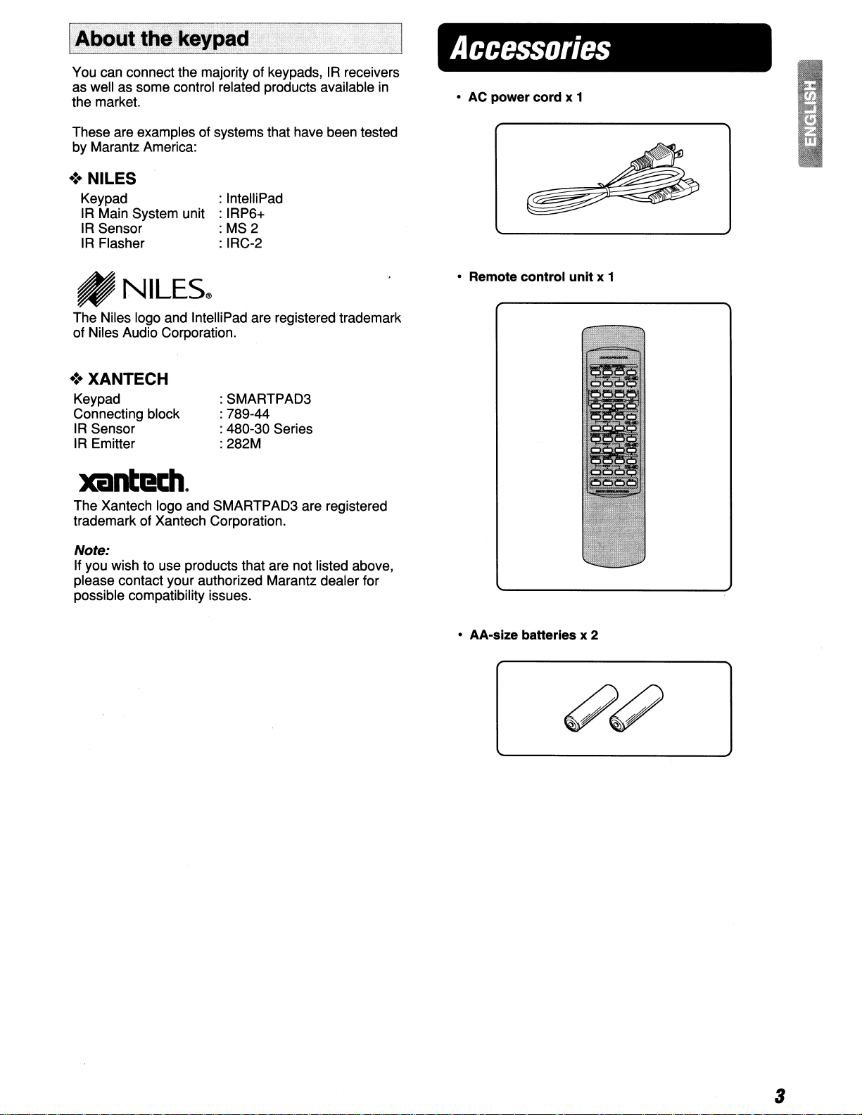
You can connect the majority of keypads,IRreceivers
as well as some control related products available
the market.
These are examples of systems that have been tested
by Marantz America:
the
keypad
...
in
.:. NILES
Keypad
IR
Main System unit
IR
Sensor
IR
Flasher
: IntelliPad
: IRP6+
:MS2
: IRC-2
Accessories
• AC power
cord
x 1
_NILES®
The Niles logo and IntelliPad are registered trademark
of Niles Audio Corporation.
•:. XANTECH
Keypad
Connecting block
IR Sensor
IR Emitter
:SMARTPAD3
: 789-44
: 480-30 Series
: 282M
xantl!l:h.
The Xantech logo and SMARTPAD3 are registered
trademark of Xantech Corporation.
Note:
If you wish to use products that are not listed above,
please contact your authorized Marantz dealer for
possible compatibility issues.
• Remote
• AA-size batteries x 2
control
unit
x 1
3
Page 8
Functional
I
Front
panel
Overview
6
~~""'''.roHE5B.ECTORI~
o
~II--~I
1
CD
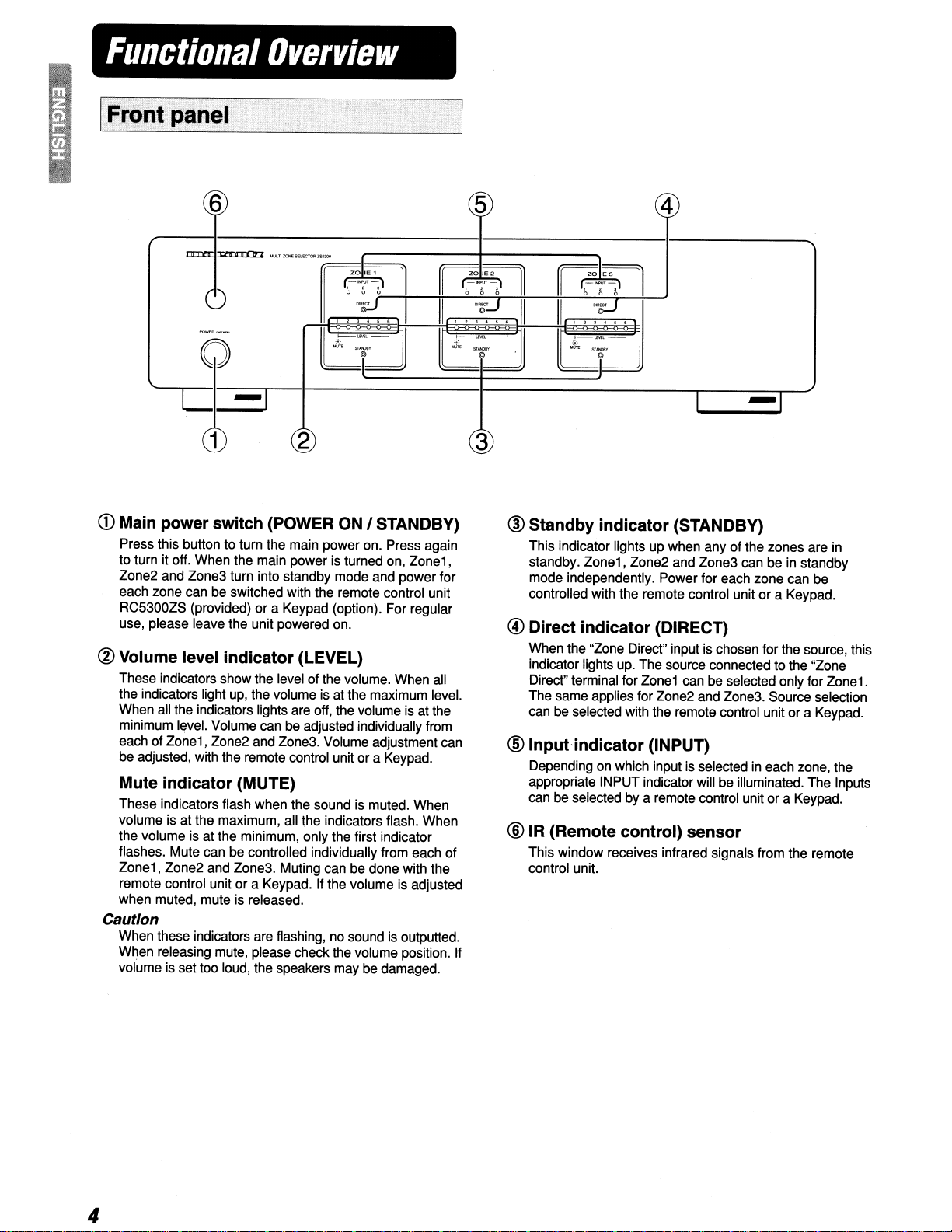
Main power switch (POWER
Press this button to turn the main power on. Press again
to turn it off. When the main power is turned on,
Zone2 and Zone3 turn into standby mode and power for
each zone can be switched with the remote control unit
RC5300ZS (provided) or a Keypad (option). For regular
use, please leave the unit powered on.
® Volume level indicator (LEVEL)
These indicators show the level of the volume. When all
the indicators light up, the volume is at the maximum level.
When all the indicators lights are off, the volume is at the
minimum level. Volume can be adjusted individually from
each of
be adjusted, with the remote control unit or a Keypad.
Mute indicator (MUTE)
These indicators flash when the sound is muted. When
volume is at the maximum, all the indicators flash. When
the volume is at the minimum, only the first indicator
flashes. Mute can be controlled individually from each of
Zonei,
remote control unit
when muted, mute is released.
Caution
When these indicators are flashing, no soundisoutputted.
When releasing mute, please check the volume position. If
volume is set too loud, the speakers may be damaged.
Zonei,
Zone2 and Zone3. Volume adjustment can
Zone2 and Zone3. Muting can be done with the
or
2
ON
I STANDBY)
a Keypad.Ifthe volume is adjusted
Zonei,
5 4
3
@ Standby indicator (STANDBY)
This indicator lights up when any of the zones are in
standby. Zone1, Zone2 and Zone3 can be in standby
mode independently. Power for each zone can be
controlled with the remote control unit
@)
Direct indicator (DIRECT)
When the "Zone Direct" inputischosen for the source, this
indicator lights up. The source connected to the "Zone
Direct" terminal for
The same applies for Zone2 and Zone3. Source selection
be
selected with the remote control unit or a Keypad.
can
@ Input-indicator (INPUT)
Depending on which input is selected in each zone, the
appropriate INPUT indicator will be illuminated. The Inputs
can be selected by a remote control unit or a Keypad.
®IR (Remote contrOl) sensor
This window receives infrared signals from the remote
control unit.
Zonei
or
a Keypad.
can be selected only for
Zonei.
4
Page 9

I
R~ar
rn
rn
rn
panel
Audio input terminal (AUDIO IN)
Connect the analog audio output from your audio device
(CD player, TV, DVD player, etc.). Up to 3 audio devices
can be connected.
Audio output terminal (AUDIO OUT)
These terminals are designed as an Audio pass through.
They can be used to when cascading one or two other
ZS5300s. Another example might be to share source
components with a dedicated home theater system etc.
Zone direct input terminal (ZONE DIRECT IN)
These terminals are only for their corresponding zone.
Connect the analog audio output terminals from your audio
device (CD player, TV, DVD player, etc.). Although up to 3
devices can be connected each to a different zone, the
device connected to "ZONE DIRECT 1" can be played
1.
only in ZONE
and ZONE DIRECT
• You can construct a powerful & unique multi-zone
system by connecting the Marantz music server
(DH9300). (1&P.13)
The same applies to ZONE DIRECT 2
3.
[!] Zone 3 pre output terminal (ZONE 3 PRE OUT)
These terminals are preamplifier output terminals for
Zone3.These terminals can be connected with other
audio devices such asanexternal amplifier.
I]]
Remote control input I output terminal
(REMOTE CONTROL)
By connecting this unit to another Marantz audio component
using a System control cable, you can remotely operate the
components as a single system.
mStatus output terminal (STATUS OUT)
These terminals are DC trigger output terminals to
determine whether power of a zone is on or off.
Connect these terminals to Keypads, etc.
• Rating of status output: 12V 100mA.
II]
Flasher input terminal (FLASHER IN)
This terminal is to control the unit from each zone. Connect
the control signal from a Keypad, etc.
[!]
Remote control
(INT.
I EXT.)
This switch is to select if the remote sensor on the front
panel work or not.
cascade connection, set this switch at INT. for the ZS5300
that functions as the maser. Set the switch at EXT. for the
slave ZS5300s.
INT. : Enable the remote sensor.
EXT. : Disable the remote sensor.
[Q]
10
select switch (10 SELECTOR)
When two or three ZS5300s are used, set independentID
numbers for each. Up to 3 ZS5300s canbeconnected.
Different ID numbers must be set for each unit.
Illl Voltage selector (VOLTAGE SELECTOR)
Select the power voltage of your location. You can select
115Vor230V.
• Be sure to disconnect the power cord when changing
this switch.
IJlI
Power inlet (AC IN)
Plug the power cord into this socket.
internal
If
you
I external switch
use two or more ZS5300s
in
00
Speaker output terminal (SPEAKERS)
Connect speakers for each zone.
• Rating of speaker impedance: 6 ohm
CAUTION:
Be
sure to use the power cord rating more than 2.5A, 250V
and 18AWG when operating 230V AC voltage.
5
Page 10

I
Remote
control
unit
(RC5300ZS)
oGLOBAL CONTROL buttons
With these buttons you can control volume, source
selection, etc. for all the zones at the same time.Iftwo or
in
three units are connected
be controlled at the same time as well.
• GLOBAL DIRECT button
This enables you to select the Zone Direct input
(dedicatedtothat
1,
2,
zones
• GLOBAL INPUT 1, 2, 3 button
This enables you to select the Input 1,2,or 3 to
be played globally with all connected ZS5300s.
• GLOBAL ON I OFF button
This enables youtoturn the power on/off for the
all zones of all connected ZS5300s. Press once
to turn on, press again to turn off.
• GLOBAL MUTE button
This enables you to turn the mute on/off for all
connected ZS5300s. Press once to turn mute
on, press again to turn mute off.
• GLOBAL VOLUME button
This enables you to control the volume up/down
for all the connected ZS5300s.
• GLOBAL ON button
This enables you to turn the poweronfor the all
zones of all connected ZS5300s.
• GLOBAL OFF button
This enables you to turn the power off for the all
zones of all connected ZS5300s.
& 3 of all connected ZS5300s.
cascade, all the zones can
zone) to be
played
in all
8 DIRECT POWER button
You can control power for each zone independently with
these buttons.
• ZONE 1 DIRECT ON button
Turn the poweronfor Zone 1 independently.
• ZONE 1 DIRECT OFF button
Turn the power off for Zone 1 independently.
• ZONE 2 DIRECT ON button
Turn the poweronfor Zone 2 independently.
• ZONE 2 DIRECT OFF button
Turn the power off for Zone 2 independently.
• ZONE 3 DIRECT ON button
Turn the poweronfor Zone 3 independently.
• ZONE 3 DIRECT OFF button
Turn the power off for Zone 3 independently
• Buttons for ZONE 1, 2, 3
The descriptions below are common. The button's
functions are the same for Zone 2 and 3; so only the
buttons for Zone 1 described.
• ZONE 1 DIRECT button
Select the "Zone Direct" input for Zone 1.
• ZONE 1 INPUT 1, 2, 3 buttons
Select the "Input 1" or "Input 2" or "Input 3" for
1.
Zone
• ZONE 1 ON I OFF button
Turn the power on/off for Zone
Press once to turn on, press again to turn off.
• ZONE 1 MUTE button
Turn the mute on/off for Zone
Press once to turn on, press again to turn off.
It
volumeisadjusted
turned off.
• ZONE 1 VOLUME button
Control the volume up/down for Zone
• ID setting button
When two or three ZS5300s are connected remote cable
together or used in same area, this allows the setting of
different ID numbers.
See "ID Code Setup" for settingIDcode for the remote
control unit. (~P.8)
Default setting the unit is ID-1.
when
1.
1.
muted,
1.
mute
is
6
Page 11

.:. Using the remote control unit
1.
Remote control
Operate the remote control unit (RC5300ZS) within a
of
distance
(remote control) window on the front of the unit.
the
If
the IR SENSOR or if there is an obstacle between
them, remote control may not be possible.
• Remote control operating range
approximately 16 feet (5m) from the IR
transmitter is pointed to a direction other than
2. Loading batteries
Batteries in this remote control unit have a life of
approximately 1 year under normal operating
conditions. When the remote control unit is not to
being used for an extended period of time, remove
the
the batteries. Also, when you notice that
are starting to run down, replace them as soon as
possible.
1.
Remove the battery cover
batteries
Remote control unit
~
.
•
~~~
ZS5300
~
Note:
• Do not use the rechargeable batteries(Ni-Cd type).
AA
2. Insert the
(-)
polarity. .
3. Close the battery cover until it clicks.
size batteries with correct (+) and
7
Page 12

/0
Code
Setup
.:. Setting10code
Ex.) Set to
Remote control
The ZS5300 system can be expanded up to 3 units.
When using
To set the remote control unit to the10number of the unit, follow the procedure below.
1. Press the SET button and hold
2.
This remote control unit has been set as
3.
When the batteries are replaced, the unit defaults to the factory setting of
Note:
Thisisimportant, because if you have changed10numbers, you will have to reset the10number when the
batteries are replaced.
10-1
unit
Press and hold SET, then
Press
10-1
and release both.
1 unit alone, set the
10
switchonthe rear panel to
it,
then press the
10-1.
10-1
button, then release both buttons.
To set the10to 2 and3,follow the same procedure.
Rear panelofthe
,
I
:) SELECTOR
"
"1",
unit
@
flDlOT'e
COHTl'IOl.
@w
@©2.~
Set to
10-1
.
ID
@ @
- 0 0
-I
is
1-
"1",
R ,
ZONE'
SP,
@
*Oefault setting for both the remote control unit and the unit
is
10-1
8
Page 13

Preparation
and
Connection
.:. Before making connections
Be sure to turn the power off for the ZS5300 and other products to be connected to ZS5300 before making
connections.
Please refer the instruction manuals for other products to make sure of the proper connections and terminals.
•:. Keypad
The keypads that can be connected to the unit are keypads and connecting boxes made by NILES and XANTECH
shown below. If you want to use products that are notinthe list below or made by other manufacturers, please
contact your authorized Marantz dealer.
•
NILES
Keypad
IR
Main System unit
IR
Sensor
IR
Flasher
: IntelliPad
: IRP6+
:
MS2
: IRC-2
·XANTECH
Keypad
Connecting block
IR
Sensor
IR
Emitter
: SMARTPAD3
: 789-44
: 480-30 Series
: 282M
Note:
When connecting a Keypad, refer to the instruction manual for the Keypad as well as for this unit.
I
Connecting
There are 2 ways to connect speakers. See the
pictures below.
.:. Connecting speaker wire
1.
Strip away approx..6/8 inch (20 mm) of wire
insulation.
speakers
.:. Connecting banana plug
Banana plug connections are also possible.
(ob~
~I
Approx. 6/8 inch
(20mm)
2.
Twist the bared wire ends tight to prevent short
circuits.
~~O~
3.
Insert the bare part of the wire into the holeinthe
each terminal as follow.
+,§sssssssss~
9
Page 14

I
Connection
.:.
NILES
system
example
To
cascade connection
ZS5300
: I ,..-----
---
..
~~l~~:::;.========:'l
:
~~!~!~!~I~lwg
12
~
v 0 T V 0 T V 0 T V 0 T V 0 T V 0 T
_NILES
MODB.
----------------
~I~~~1i2
A A A A A A
IAP6+
~ ~1i2 ~ ~112 ~
Set8JR
INPUTS
-------'
r
flASHER
lEVEL---,
~112~~
Remote
Status
Analog
Speaker
,
®
IR
,
,
·
,
·
·
·
,
·
l\
__
~~
_
IR
Data
Flasher
::11~::~::~~
·
·
·
~--------------------------------------,
·
I @ Analog
I@ out
l_
-
T.!>
--.!>
II@Analo
--.!>
Out
Out
r
.
I
,
I
, • out
l_
(-
- _.L.!>
In Remote
g
In
Remote
:
DC
power supply
plugged
unswitchedACoutlet.
into
an
CD Player
MARANTZ
DVD Player
MARANTZ
Tuner
MARANTZ
~
,
,
I
,
,
·
,
,
'···i······
,
..
·
,
,
·
,
I
,
·
,
,
,
·
,
,
,
·
,
·
,
·
,
,
,
,
·
:IRFlasher
:
IRC-2
:
:
,
••••••
HH
---
..
':-----------------
I
:'r:::
:--------
o
~~
~
.r~~K
~--~
"~L1FIER
INPUT
~
~~
~~
='"
o
_~LES
11~i;nl
~
~~~~
~~,~,~
...
l,-:,,:-:."":".-~':'".
-.
_:-:.-.-.-.-
---~------------"
,
!~6---0""A"'\.O
Si+~_.~
.......
:"'1
"!!LAY
(~
~
~
~
":~~ER
'6~:~
I~~~~II~~~~I
__
.,,~
, a remote location
..
-.-.-.**':
.
.I.~/
STA_
I'IIDIIACK
"NILES
--::=:--
I.~i;n
1.1...
~
1~'~
••
" - • , a remote location
,.~/
~
MS·2IRSensor
......
{@@}
Zone-2
MS-2IRSensor
{@
@}
......
in
in
10
Analog @ @ @
out @ @ @
2 3 4 HOD Player
Zone-3
MARANTZ
Page 15

.:. XANTECH system
To cascade connection
Z85300
0
0 0
0
1@Analog
,
--:!)
-
@ out
L:!)
In
Out
l
r
,
I
,
I I @ Analog
l I·out
(:
_:
I~
~ut
,
I
,
I
,
I
,
I
,
789-44
CONNECTING BLOCK
U)
0
0
:::>
>
Q
t:c
z
N
t3~g;
..
...
_-----_
..
, . ,
·
..
·
..
·..
I t
,,---
·.
I
~--------------------------
, .
DC power supply
plugged into an
--..,.,-'-..u
Remote
Remote
unswitched AC outlet.
0
IR
0
RCVR
...
--------------------,
CD
Player
MARANTZ
DVD Player
MARANTZ
Tuner
MARANTZ
~
___L__
I
,
,
l
·
·
·
·
·
,
·
·
,
·
·
·
·
,
·
,
·
·
·
·
·
'--T-----
.
,
I
Remote
Status
Analog
Speaker
-----;-
-----
a
PM110 I
SMART
PAD!"
PROGRAMMABLE MODULE
~~~!~:~
~~l~,
...
.. -
~
L'~;~RR+
L'~":~RR.
INPUT
OUTPUT
~
---6'l
c:
1..
~_.?_~~
fi
':
~'7--
IR
Data
Flasher
'
i
;.,~
I
lit
'mini
480-30
IR
'
..
1
7-1001
---
~~
series
Receivers
@ @
White stripe
'\
ribbon cabte
plug
removed
-------
--------------""'\_--------.
o
t--_o
PM110
SMART
PAD!"
PROGRAMMABLE MODULE
oil
c_i:!,
-------------
...-------'j---------..
, Speaker
~o
a
PM110
SMART
PAD!"
PROGRAMMABLE MODULE
'I
~!
l
Speaker
L R
...
~~~..~_
..............
GND
I \
with
- ' :
-
Zo~e-1
Speaker
L R
LR
,
Analog @ @ @
out@@@
2 3 4
HOD
Player
MARANTZ
11
Page 16

.:.
Cascade
Note:
To change the positions of the EXT./INT. switch and theIDswitch, turn off the main power switch of the ZS5300.
When the main power switch is on, changing the positions do not affect.
connection
ZS5300 (Master)
ZS5300 (Slave)
~
Analog
'@ out
!
! 1 Analog
l 1 out
-- -
/~----·I----~
T~
Remote
""--'
@ @ @
@ @ @
2
3
CD Player
MARANTZ
DVD Player
MARANTZ
MARANTZ
4
HOD Player
MARANTZ
'---'
'---'
Tuner
'---'
'---'
Set to EXT
"-
"-
"-
"-
EXT. INT.
~
~
---
--Analog
123
00
+
Remote
Set to 2
12
Page 17

.:. Connection with the DH9300
Z85300
[
"=,-;,-='-1"·;
~
o
Speaker
!~1:j~I~
---
--Analog
--
----- -- Video
~~
Remote
Speaker
Zone-1
Zone-2
Speaker
l _ _ _ _ _ j
DH9300 :
~..;..;:;..,,;:....::..;;'-----------:-:-:
0'
'0
~.;~,;~.;
~ ~
-~---_r_---------I-
o'
'0
~,,2rn~
()JT
ovr
@j@j@j
,-----------------------------,
TV
Zone-3
,-----------------~------------------------------
, ,
I
,--------------,
-.J
-':"-_-~-_-:':""-
::
I • f
@
@.@
,@
__
OUT'
@. @.
@.
0lIf'
@)
@ @
1oNAL.Ol'~
..
-"''''''''''''''''''''''''''''''''''''''''''''''''
I
1
1II11Oft101
@,
@.
@,
0lIl,
0lII'
@
@,
@.
-------
--
-
..
-I-----------.,r-------r-./
......
13
Page 18

.:. Connecting
When using speakers which might need high power to drive (ex. some outdoor speakers), you might need more
power than the ZS5300 can provide. If you need more power, you can connect the "ZONE 3 PRE OUT" to an
external power amplifier.
Sound level can be adjusted with Volume Up/Down on ZS5300.
external
power
amplifier
Z85300
Outdoor speaker
.:. Connecting
When all the connections are made, plug the power
cord into the power outlet.
power
cord
.:. Setup
This is an example to construct 3-zone system with a
NILES keypad.
See the picture Connection Example "NILES system"
(~P.
10).
Power amplifier
I
,---+.....,@- @-:
@ @
@=
@=
-~.
@-
MA61 00
Power amplifier
MA6100
Outdoor speaker
When all the connections are made, teach the
keypad the remote commands.
To teach the commands to the keypad or more
information, please refer to the instruction manual of
your keypads.
14
Page 19

Operation
.:.
Refer
to connection example
Examples
"NILES
system
II
(~
P.10)
Main room
o
1.
-
1.
light up
---
o 0
.----.0
, t 3 • 5 •
~~----'
~.
"@
J)
6.
light up
-I
3. light up
.__-------------
1.
ZONE 1
2.
4. flash
6.
4.
1.
1.
Press the CD buttononthe keypad.
The power of ZS5300's Zone 1 is turnedonand
the input source is switched to Input
Pressing the POWER buttononthe keypad also
turnsonthe power.
2.
Press the PLAY buttononthe keypad.
CD player begins to play.
3.
Press the
The volume level of ZS5300's Zone 1 is
increased.
Also pressing the
the volume level.
4.
Press the MUTE button on the keypad to mute the
sound.
The volume level indicators of ZS5300's Zone 1
flashes.
To release the mute, press the MUTE button
again or press the
5.
Press the STOP buttononthe keypad.
The CD player stops.
VOLUME'"
VOLUME"
VOLUME'"
buttononthe keypad.
3.
button decreases
or
...
6.
Press the POWER button on the keypad.
The power of ZS5300's Zone 1 is turned off and
the STANDBY indicator lights up.
15
Page 20

Remote
Code
List
.:. Remote code
list
(RC-S
Power ON/OFF
Power ON
Power OFF
Volume up
Volume down
Mute
INPUT 1
INPUT 2
INPUT
Direct
Power ON/OFF
Power ON
Power OFF
INPUT 1
INPUT
INPUT
Direct
Mute ON/OFF
Volume up
Volume down
Power ON/OFF
Power ON
Power OFF
INPUT 1
INPUT
INPUT 3
Direct
Mute ON/OFF
Volume up
Volume down
Power ON/OFF
Power ON
Power OFF
INPUT 1
INPUT
INPUT
Direct
Mute ON/OFF
Volume up
Volume down
Set
ID-1
ID-2
ID-3
extension)
3
in
2
3
in
2
in
2
3
in
161210
161211
161212
161600
161700
161319
160039
160049
160059
160060
161220
161221
161222
160030
160031
160032
160017
161310
161610
161710
161230
161231
161232
160040
160041
160042
160024
161311
161611
161711
161240
161241
161242
160050
160051
160052
160027
161312
161612
161712
161210
161211
161212
161600
161700
161319
160039
160049
160059
160060
161223
161224
161225
160033
160034
160035
160018
161313
161613
161713
161233
161234
161235
160043
160044
160045
160025
161314
161614
161714
161243
161244
161245
160053
160054
160055
160028
161315
161615
161715
161210
161211
161212
161600
161700
161319
160039
160049
160059
160060
161226
161227
161228
160036
160037
160038
160019
161316
161616
161716
161236
161237
161238
160046
160047
160048
160026
161317
161617
161717
161246
161247
161248
160056
160057
160058
160029
161318
161618
161718
Global control code
Global control code
Global control code
Global control code
Global control code
Global control code
Global control code
Global control code
Global control code
Global control code
16
ID
initial:
ID
setting:
ID-1
Push and hold SET first and
10-*
buttons next simultaneously.
(*=1
or 2 or
3)
Page 21

Troubleshooting
In
case of trouble with the unit, first check the following before calling for service.
1.
Are all the connections made properly?
2.
Are you operating the unit properly by following user's guide?
3.
Are the other products working properly?
If
the unit still does not work properly, check the items showninthe following table.
If
your trouble cannot be solved with the remedy actions listed in the following table, malfunction of the internal
circuitry is suspected; immediately unplug the AC power cord and contact a Marantz authorized dealer or service
center.
The
amplifier
does
not
The
indicator
not
function.
Soundisproduced
speaker
Soundisnot
Doesn't
Cascade.
does
light
up.
lightsupbut
systems.
producedatall.
work
properly
Problem
not
work
only
whenitis
the
from
and
the
amplifier
oneofthe
connected
indicator
will
to
Remedy
• Check if the power cord is plugged properly into
AC power outlet.
• Check the settings of the INPUT SELECTOR,
VOLUME control.
• Check if the MUTE function is de-activated.
(The MUTE indicator is OFF.)
• Turn the power off and change the connections of
the left and right speaker systems. If sound still
does not come out from the same speaker system,
check the connection cords or the speaker system
itself.
• Check the settings of the INPUT SELECTOR.
• Check that the speaker cords are connected
properly.
• Check that the connection cords with RCA pin
plugs are connected properly.
• Check the ID switch of the rear panel is set
properly.
ID
• Check the
properly.
setting of the remote controller is set
an
Care
This section describes the care and maintenance
tasks that must be performed to optimize the
operation of your Marantz equipment.
and
Maintenance
.:. Cleaningofthe external surfavesofthe
unit
The exterior finish of your unit will last indefinitely
with proper care and cleaning.
Never use scouring pads, steel wool, scouring
powders or harsh chemical agents, alcohol, thinners,
benzene, insecticide or other volatile substances as
these will mar the finish of the equipment.
Likewise, never use cloths containing chemical
substances. If the unit gets dirty, wipe the external
surfaces with a soft, lint-free cloth:
17
Page 22

,
Specification
Rated power
Zone1
Zone2
Zone3
THD (40Hz - 20KHz)
UR
UR
UR
Input sensitivity 300mV / 60W Output
Input impedance 20K ohms
Frequency response
Signal to noise ratio 85dB
Power requirement 115V / 230V AC 50/60Hz
Power consumption
output
(40Hz -20KHz) 60W 6-ohm / Channel
(40Hz -20KHz) 60W 6-ohm / Channel
(40Hz -20KHz) 60W 6-ohm / Channel
0.05%
(-1
dB) 10Hz to 30KHz
'"
6-ohm
100W
Dimensions (Maximum)
Width 17.32 inches (440 mm)
Height 4.53 inches (115 mm)
Depth 13.31 inches (338 mm)
Weight 18.74 Ibs (8.5 Kg)
Accessories
AC power cord 1
Remote control unit (RC5300ZS) 1
AA-size batteries 2
Design and specifications are subjecttochange without notice.
18
Page 23

www.marantz.com
You,
can find your nearest authorized distributor or dealer on our website.
PrintedinJapan
.....
.......
]I[
@
isaregistered
trademark.
01/2008 00M02AJ851254 mzh-g
Page 24

For
U.S.A.
lDapantz®
Limited
Marantz
Products
1.
The
year
chase
Amplifiers,
Tuners,
Players,
Learning
front
2.
VCR's,
Products
original
3.
Rear
labor
4.
DLP
the
Whatiscovered
Exceptasspecified
to
correct
lowing
1.
Damage,
formance
a)
thorized
b)
uretofollow
c)
Marantztorepair
d)
to
e)
2.
Cleaning,
charges
the
Warranty
America,
for
the
periods
following
warranty
date:
Pre
Integrated
CD-Recorders,
Remote
Projectors.
Wallvisions,
have
purchase
Projection
from
the
lamps
have
origianl
are
Accident,
Any
the
product.
purchase
and
all
defectsinmaterials
not
coveredbythe
deterioration,
specifications
product
Improper
Repairorattempted
shipmentofthe
carrier).
Any
cause
initial
incurred
Inc.
("Marantz")
indicated:
Marantz
for
a 1
original
Audio/Video
both
Parts&Labor,
Amplifiers,
Amplifiers,
CD
Control
Plasma
year
warranty
date.
TVs
have
purchase
a 90
day
date.
whatisnot
below,
actsofnature,
installation,
instructions
other
set-up,
this
malfunctionorfailuretomeet
resulting
modification.
repairbyanyone
the
product.
thanaproduct
check-Ups
for
installation,
warrants
Pre
Tuners,
Players,
Devices,
a 2
year
warranty
the
following
components,
from
the
Amplifier-Processor-
Receivers,
Universal
TVs,
for
parts
date.
for
Audio
warranty
Cassette
LCD
and
parts
TVs&HDD
labor
and
Marantz
have
original
DVD
Decks,
Dock&DLP
from
for
parts
labor
covered
warranty
warranty:
misuse,
removalormaintenance,orfail-
supplied
product
covers
parts
and
and
workmanship.
from:
abuse,
neglectorunau-
with
the
product.
not
(claims
removalorreinstallation
mustbepresented
defect.
withnodefects
The
authorized
found,
a 3
pur-
the
and
from
labor
fol-
per-
by
or
of
Who
may
enforce
This
warranty
Whatwewill
We
will
pay
eredbythe
in
the
next
How
you
can
1.Ifyour
calling
name
and
stations
vice
not
return
tion.
2.
You
must
the
product
covered
chargestoany
sessionsorterritories.
3.
Whenever
original
the
maybeenforced
pay
for
for all
warranty.
sectionofthis
get
service
unit
needs
toll-free
dated
1-800-270-4533.
locationofoneormore
from
your
unittothe
pay
any
for service.
under
warranty,
destination
warranty
sales
Limitationofimplied
All
implied
and
fitness for a
the
lengthofthis
warranties,
particular
warranty.
Exclusionofdamages
Marantz
replacementofthe
notbeliable for
in
lossofuseofthe
dental,
How
liability for
productatMarantz's
damagetoother
Marantz
state
products,
product,orany
consequential,orotherwise.
law
relatestothe
warranty
onlybythe
labor
and
material
Paymentofshipping
warranty.
service,
contact
which
service
shipping
However,ifthe
serviceisrequired,
receiptorother
canbeobtained.
factory
charged
we
will
within
warranties
including
any
damages
defective
warrantiesofmerchantability
purchase,
productislimitedtorepair
products
based
other
warranty
original
expenses
chargesisdiscussed
Marantz
We
will
authorized
without
if it is
necessary
pay
the
the
United
you
proofofdateofpurchase.
are
limitedinduration
option.
causedbyany
upon
damages,
purchaser.
for
items
service
advise
referral
youofthe
Marantz
Please
prior
authoriza-
necessarytoship
repairs
return
must
inconvenience
shipping
States,
present
Marantz
whether
its
defects
cov-
by
ser-
do
are
pos-
the
to
or
shall
or
inci-
3.
Any
productonwhich
modifiedorremoved.
4. Batteries.
5.
Accessories,
mounting
antenna
6.
Warrantyisvoidifpurchase
thananauthorized
including
hardware
and
detachable
the
but
and
power
Marantz
serial
not
brackets,
was
dealer.
Marantz America, Inc.
100
Corporate
Mahwah,
Phone.
800-654-6633
NJ,
Drive,
07430
Fax.
201-762-6686
number
limited
cords.
made
has
to,
batteries,
cleaning
from
been
defaced,
cables,
accessories,
anyone
other
Some
statesdonot
warranty
of
incidentalorconsequential
or
exclusions
This
have
PRINTEDINJAPAN
lasts
warranty
other
rights
allow
and/ordonot
may
not
gives
you
which
limitationsonhow
allow
the
damages,sothe
applytoyou.
specific legal rights,
vary
from
state
6/06
longanimplied
exclusionorlimitation
above
limitations
and
you
may
to state.
3133
115
78064
092J854117
also
Page 25

Dlapantz®
MARANTZ
Marantz
products
3-year
purchase
Amplifiers;
Integrated
Recorders;
Remote
Projectors.
1
year
warranty
CANADA
Canada
for
the
warranty
date
:
Pre
Amplifiers;
CD
Control
("Marantz")
periods
for
both
Amplifiers;
Players;
Devices;
for
parts
date:
HD
Digital VCR's
90
day
warranty
for
parts
date:
DLPlamps
3-year
warranty
warranty
Plasma
WhatisCovered
Exceptasspecified
labor
to correct all defectsinmaterials
following
1.
Damage,
performance
a)
b)
c)
d)
e)
2.
Cleaning, initial set-up,
or
reinstallationofthe
3.
Any
defaced,
4. Accessories,
mounting
antenna
Warrantyisvoidifpurchase
5.
other
for
Labour,
for
the
Panel
:
Displays
and
WhatisNot
are
not
coveredbythe
deterioration,
specifications
Accident;
unauthorized
Improper
failuretofollow
product.
Repairorattempted
by
Marantztorepair
Any
presentedtothe
Any
charges
product
and
thananauthorized
actsofnature;
installation,
shipment
cause
other
incurred
on
modifiedorremoved.
including
hardware
detachable
LIMITED
warrants
indicated:
Parts&Labour,
Pre
Amplifier-Processor-Tuners;
Tuners;
and
and
below,
product
product.
which
Receivers;
Audio
Universal
labour
labour
2-year
warranty
Covered
this
warranty:
malfunctionorfailuretomeet
resulting
modification.
removalormaintenance,
instructions
repairbyanyone
the
of
the
carrier)
thanaproduct
check-ups
for
the
but
not
and
brackets,
power
Marantz
WARRANTY
the
following
from
DVD
Cassette
from
from
warranty
product.
product
installation,
serial
limited to, batteries, cables,
cords.
Decks;
Dock&DLP
the
original
the
original
for
parts
covers
and
workmanship.
from:
misuse;
was
dealer.
abuse;
supplied
(claims
defect
withnodefects found,
number
cleaning
made
Marantz
the
original
Players; CD-
Learning
front
purchase
purchase
and
1·year
parts
neglect;
with
not
authorized
must
removal
has
accessories,
from
anyone
been
and
The
the
be
or
or
Who
May
Enforce
Only
the
WhatWeWill
We
will
coveredbythe
discussedinthe
How
You
Can
1.Ifyour
any
authorized
CANADA
station
MARANTZaslisted
unittothe
2.
You
must
ship
the
repairs
return
Canada.
3.
Whenever
the
original
purchase.
LimitationofImplied
All
implied
merchantability
limitedindurationtothe
original
Pay
pay
for
Get
unit
(if
is
factory
pay
product
are
shipping
warranty
the
Warranty
purchaser
For
all
labor
warranty.
next
sectionofthis
Service
needs
service, it
MARANTZ
you
are
MARANTZ
without
any
shipping
for service.
covered
dated
under
charges
service is
sales
warranties
warranties,
and
fitness
may
and
Paymentofshipping
uncertain
authorized,
below).
prior
receiptorother
foraparticular
lengthofthis
Exclusionofdamages
Marantz
or
shall
any
inconvenienceorlossofuseofthe
damages,
Some
implied
incidentalorconsequential
and
This
also
liability for
replacementofthe
notbeliable for
defectsinMarantz
whether
provinces
warranty
exclusions
warranty
have
other
incidental, consequential,orotherwise.
do
lasts
may
gives
rights,
any
defective
productatMarantz's
damagetoother
products,
not
allow
and/or
damages,sothe
not
applytoyou.
you
specific legal
which
vary
MARANTZ Canada
DivisionofD&M
5-505
Apple
Markham,
L3R
5B1
1-888-258-9361
www.marantz.com
Creek
Ontario
Canada
Blvd.,
Inc.
enforce
material
maybetakenorshipped
service
charged
warranty,
to
including
limitations
does
this
warranty.
expenses
warranty.
stationorMARANTZ
as to
whetheraservice
Pleasedonot
authorization.
if it is
However,ifthe
we
any
destination
required,
productislimitedtorepair
not
from
you
warranty.
products
damages
product,orany
allow
above
rights,
provincetoprovince.
for
charges
please
return
necessary
necessary
will
must
proofofdate
warranties
purchase,
option.
caused
based
on
how
the
exclusion
limitations
but
items
contact
your
pay
the
within
present
are
Marantz
upon
other
long
you
may
is
to
to
of
of
by
an
of
PRINTEDINJAPAN
3/07
00M183J854016
Page 26

Dlapantz@
GARANTIE
Marantz
pour
les
3
ansdegarantie
effetapartirdela
Amplificateurs,
syntoniseurs;
recepteurs,
pIa
tinesitcassette
Dock
1ande
effetapartirdela
Magnetoscope
90
joursdegarantie
effetapartirdela
Lampes
3
ansdegarantie
les
piecesetunande
Ecrans it
Ce
qui
est
A
l'exception
garantie
tousles
qui
suit
1. Les
ouIefaitdene
resultant
a) accident, acte
b) installation incorrecte,
c)
d)
e) cause
2.
L'entretien, l'installation initiale, toute verificationdeproduit
ou
l'installation,Iedeplacementoula reinstallationduproduit.
3.
Tout
ou
4.
Les
cables,
antennesetcordonsdesecteur
5.Lagarantie
chezunrevendeur
Qui
peut
Seulelapersonne
appliquer
LlMITEE
Canada
periodes
universeletprojecteurs
garantie
DLP
("Marantz")
indiquees
pour
date
Preamplificateurs,
amplificateurs
lecteurs
pour
date
numerique
date
DE
:
les
piecesetla
d'achatduproduit
DVD,
audio,
pour
telecommandes
les
piecesetla
d'achatduproduit
HD
les
piecesetla
d'achatduproduit
pourlamain
garantie
plasma
couvertetpas
decequi
couvre
defautsdematerieloude
n'est
dommages,
impropre
autorisee;
d'un
Ie
reparations
personne
envoi
presenteesautransporteur)
aucun
produit
enleve.
accessoires
faire
les piecesetla
pas
d'un
emploi
produit;
de
autre
defautn'a ete trouve,outous frais encouIUS
materiaux
n'est
appliquerlagarantie
la garantie.
couvert
est
couvert
(e) :
dontIenumerodeserie a
par
deterioration,
pas
respecter les specifications d'executions
de
la nature, abus, negligence, utilisation
ou
d'une
contraire aux instructions fournies avec
ou
tentatives
non
reconnue
produit
qu'un
defautdeproduit.
incluant
de
support,
pas
valable si
non
reconnu
qui
a achete Ie
MARANTZ
garantie
CANADA
les
produits
main
d'muvre
:
Pre-ampli-processeurs-
integres,
enregistreurs
avant
DLP.
syntoniseurs,
CD,
programmables,
main
d'muvre
:
main
d'muvre
:
d'muvre,2ansdegarantie
pourIepanneau
:
parlagarantie
mentionne
main
fabricationduproduit.
la garantie :
defautsdefonctionnement,
modification
deplacement,
par
(les
reclamations
mais
accessoiresdenettoyage,
detachables.
l'achataete
par
produit
ci-dessous,
d'ceuvre
de
reparations
Marantz;
ete
non
limites
Marantz.
al'origine
afindereparer
de
maintenance
efface, modifie
faitauCanada
suivants
prenant
lecteurs
prenant
prenant
:
produit
par
doivent
aux,
peut
CD,
pour
cette
Ce
non
ou
une
etre
pour
piles,
faire
Notre
paiement
Nous
paierons
pour
tous
des
fraisdelivraison
cette garantie.
Comment
1. Si
2.
3.
Limites
Toutes
valeur
sont
Exclusion
La responsabilitedeMarantz
produit
remplacement
interviennentitdes
Marantznesera
bases
ou
Certaines
duree
l'exclusiondedommages
exclusions
vous
vous
pouvez
autorise
(DansIecasouvousn'etes
service
pouvez
de
telephone
appareil
Vous
appareil
Toutefois, si les
la garantie,
et
ce quelle
Lorsque
sous
d'achat
des
les
marchandeetspecifique
limitees
des
surIederangementoula
tout
autre
d'une
tous
les fraisdepiecesetde
les
produits
pouvez
avez
l'envoyerouIe
Marantz
est
autoriseounonitreparer
contacter
couverts
est
obtenirIeservicedereparation
besoindefaire
ou
directement
Marantz
ci-dessous). Veuilleznepas
al'usine sans autorisation prealable.
devez
payer
les fraisdelivraison
a besoind'etre
reparations
nous
payerons
que
soit la destinationauCanada.
vous
envoyez
garantie,
garanties
defectueuxence
provincesnepermettent
vous
devez
(ticketouautre
implicites
garanties
dansladuree
implicites,ycompris
dommages
du
produit
produits
pas
tenu
dommage
garantie
mentionnees
sous-entendue
qu'il
ci-dessus
avotre cas.
Cette
garantie
vous
pouvez
d'une
provinceitl'autre.
Cette
garantie
vous
donne
aussi
avoird'autres
n'est
seulement
MARANTZ Canada
DivisionofD&M
5-505
Apple
Markham,
L3R
5B1
1-888-258-9361
www.marantz.com
PRINTEDINJAPAN
Creek
Ontario
Canada
Blvd.,
Inc.
3/07
main
d'ceuvre
par
la garantie. Le
aborde
fortuits ; ainsi les limitationsetles
dans
la section
reparer
deposer
pas
Canada
envoyeauservice
necessaires
les fraisderetour
votre
joindre
preuve
it la
longueurdecette garantie.
est
limitee
qui
concernelareparation
en
question.Sides
autres
responsable
perte
soit fortuit, indirectouautre.
des
droits
valable
votre appareil,
chezunatelierdeservice
chez
Marantz
surdesavoir siunatelier
votre appareil,
a
l'
adresseetau
dansIecasOUvotre
sont
appareil
d'achat)
pour
pasdelimites
et/ou
peuventnepas
legaux specifiques,
droits
pour
une
copiedela facture
un
achat
pour
que
ceuxdeMarantz,
des
d'utilisationduproduit
ne
qui
qu'au
Canada.
paiement
suivante
renvoyer
des
reparations.
couvertes
d'expedition
un
les
garanties
particulier,
n'importe
dommages
dits
dommages,
quant
permettent
s'appliquer
peuvent
00M183J854016
vous
Canada
vous
numero
votre
par
service
quel
ou
ala
pas
mais
varier
de
de
de
Ie
 Loading...