

Page 1

Model ZR6001 User Guide
AV Surround Receiver
Page 2
CAUTION
RISK OF ELECTRIC SHOCK
DO NOT OPEN
CAUTION: TO REDUCE THE RISK OF ELECTRIC SHOCK,
DO NOT REMOVE COVER (OR BACK)
NO USER-SERVICEABLE PARTS INSIDE
REFER SERVICING TO QUALIFIED SERVICE PERSONNEL
The lightning flash with arrowhead symbol within an equilateral triangle is
intended to alert the user to the presence of uninsulated “dangerous voltage”
within the product’s enclosure that may be of sufficient magnitude to constitute
a risk of electric shock to persons.
The exclamation point within an equilateral triangle is intended to alert the user
to the presence of important operating and maintenance (servicing) instructions
in the literature accompanying the product.
WARNING
TO REDUCE THE RISK OF FIRE OR ELECTRIC SHOCK,
DO NOT EXPOSE THIS APPLIANCE TO RAIN OR MOISTURE.
CAUTION:
TO WIDE SLOT, FULLY INSERT.
ATTENTION:
LAME LA PLUS LARGE DE LA FICHE DANS LA BORNE CORRESPONDANTE
DE LA PRISE ET POUSSER JUSQU’AU FOND.
NOTE TO CATV SYSTEM INSTALLER:
This reminder is provided to call the CATV (Cable-TV) system installer’s attention to Section 820-40 of the
NEC which provides guidelines for proper grounding and, in particular, specifies that the cable ground
shall be connected to the grounding system of the building, as close to the point of cable entry as practical.
NOTE:
This equipment has been tested and found to
comply with the limits for a Class B digital device,
pursuant to Part 15 of the FCC Rules. These limits
are designed to provide reasonable protection
against harmful interference in a residential
installation. This equipment generates, uses and
can radiate radio frequency energy and, if not
installed and used in accordance with the
instructions, may cause harmful interference to
radio communications. However, there is no
guarantee that interference will not occur in a
particular installation. If this equipment does cause
harmful interference to radio or television
reception, which can be determined by tuning the
equipment off and on, the user is encouraged to try
to correct the interference by one or more of the
following measures:
TO PREVENT ELECTRIC SHOCK, MATCH WIDE BLADE OF PLUG
POUR ÉVITER LES CHOCS ÉLECTRIQUES, INTRODUIRE LA
- Reorient or relocate the receiving antenna.
- Increase the separation between the equipment
and receiver.
- Connect the equipment into an outlet on a circuit
different from that to which the receiver is
connected.
- Consult the dealer or an experienced radio/TV
technician for help.
NOTE:
Changes or modifications not expressly approved
by the party responsible for compliance could void
the user’s authority to operate the equipment.
IMPORTANT SAFETY
INSTRUCTIONS
READ BEFORE OPERATING EQUIPMENT
This product was designed and manufactured to
meet strict quality and safety standards. There are,
however, some installation and operation
precautions which you should be particularly
aware of.
1. Read Instructions – All the safety and
operating instructions should be read before
the product is operated.
2. Retain Instructions – The safety and operating
instructions should be retained for future
reference.
3. Heed Warnings – All warnings on the product
and in the operating instructions should be
adhered to.
4. Follow Instructions – All operating and use
instructions should be followed.
5. Cleaning – Unplug this product from the wall
outlet before cleaning. Do not use liquid
cleaners or aerosol cleaners. Use a damp
cloth for cleaning.
6. Attachments – Do not use attachments not
recommended by the product manufacturer
as they may cause hazards.
7. Water and Moisture – Do not use this product
near water-for example, near a bath tub, wash
bowl, kitchen sink, or laundry tub, in a wet
basement, or near a swimming pool, and the
like.
8. Accessories – Do not place this product on an
unstable cart, stand, tripod, bracket, or table.
The product may fall, causing serious injury to
a child or adult, and serious damage to the
product. Use only with a cart, stand, tripod,
bracket, or table recommended by the
manufacturer, or sold with the product. Any
mounting of the product should follow the
manufacturer’s instructions, and should use a
mounting accessory recommended by the
manufacturer.
9. A product and cart combination should be
moved with care. Quick stops, excessive
force, and uneven surfaces may cause the
product and cart combination to overturn.
10. Ventilation – Slots and openings in the cabinet
are provided for ventilation and to ensure
reliable operation of the product and to protect
it from overheating, and these openings must
not be blocked or covered. The openings
should never be blocked by placing the
product on a bed, sofa, rug, or other similar
surface. This product should not be placed in
a built-in installation such as a bookcase or
rack unless proper ventilation is provided or
the manufacturer’s instructions have been
adhered to.
11. Power Sources – This product should be
operated only from the type of power source
indicated on the marking label. If you are not
sure of the type of power supply to your home,
consult your product dealer or local power
company. For products intended to operate
from battery power, or other sources, refer to
the operating instructions.
Page 3
12. Grounding or Polarization – This product may
be equipped with a polarized alternatingcurrent line plug (a plug having one blade
wider than the other). This plug will fit into the
power outlet only one way. This is a safety
feature. If you are unable to insert the plug
fully into the outlet, try reversing the plug. If the
plug should still fail to fit, contact your
electrician to replace your obsolete outlet. Do
not defeat the safety purpose of the polarized
plug.
AC POLARIZED PLUG
13. Power-Cord Protection – Power-supply cords
should be routed so that they are not likely to
be walked on or pinched by items placed upon
or against them, paying particular attention to
cords at plugs, convenience receptacles, and
the point where they exit from the product.
14. Protective Attachment Plug – The product is
equipped with an attachment plug having
overload protection. This is a safety feature.
See Instruction Manual for replacement or
resetting of protective device. If replacement
of the plug is required, be sure the service
technician has used a replacement plug
specified by the manufacturer that has the
same overload protection as the original plug.
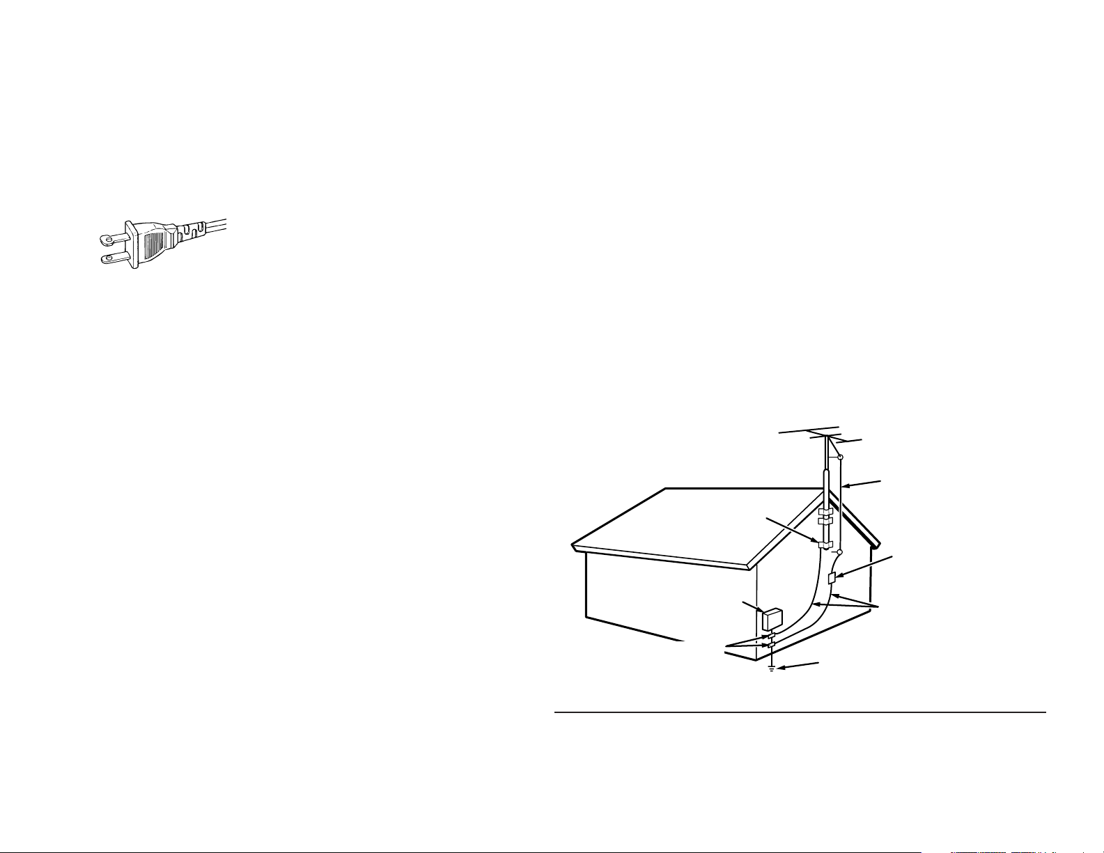
15. Outdoor Antenna Grounding – If an outside
antenna or cable system is connected to the
product, be sure the antenna or cable system
is grounded so as to provide some protection
against voltage surges and built-up static
charges. Article 810 of the National Electrical
Code, ANSI/NFPA 70, provides information
with regard to proper grounding of the mast
and supporting structure, grounding of the
lead-in wire to an antenna discharge unit, size
of grounding conductors, location of antennadischarge unit, connection to grounding
electrodes, and requirements for the
grounding electrode. See Figure 1.
16. Lightning – For added protection for this
product during a lightning storm, or when it is
left unattended and unused for long periods of
time, unplug it from the wall outlet and
disconnect the antenna or cable system. This
will prevent damage to the product due to
lightning and power-line surges.
17. Power Lines – An outside antenna system
should not be located in the vicinity of
overhead power lines or other electric light or
power circuits, or where it can fall into such
power lines or circuits. When installing an
outside antenna system, extreme care should
be taken to keep from touching such power
lines or circuits as contact with them might be
fatal.
18. Overloading – Do not overload wall outlets,
extension cords, or integral convenience
receptacles as this can result in a risk of fire or
electric shock.
19. Object and Liquid Entry – Never push objects
of any kind into this product through openings
as they may touch dangerous voltage points
or short-out parts that could result in a fire or
electric shock. Never spill liquid of any kind on
the product.
20. Servicing – Do not attempt to service this
product yourself as opening or removing
covers may expose you to dangerous voltage
or other hazards. Refer all servicing to
qualified service personnel.
21. Damage Requiring Service – Unplug this
product from the wall outlet and refer servicing
to qualified service personnel under the
following conditions:
a. When the power-supply cord or plug is
damaged.
b. If liquid has been spilled, or objects have
fallen into the product.
c. If the product has been exposed to rain or
water.
d. If the product does not operate normally by
following the operating instructions. Adjust
only those controls that are covered by the
operating instructions as an improper
adjustment of other controls may result in
damage and will often require extensive work
by a qualified technician to restore the product
to its normal operation.
e. If the product has been dropped or damaged
in any way, and
f. When the product exhibits a distinct change in
performance – this indicates a need for
service.
FIGURE 1
EXAMPLE OF ANTENNA GROUNDING AS PER
NATIONAL ELECTRICAL CODE, ANSI/NFPA 70
GROUND
CLAMP
ELECTRIC
SERVICE
EQUIPMENT
GROUND CLAMPS
NEC - NATIONAL ELECTRICAL CODE
22. Replacement Parts – When replacement
parts are required, be sure the service
technician has used replacement parts
specified by the manufacturer or have the
same characteristics as the original part.
Unauthorized substitutions may result in fire,
electric shock, or other hazards.
23. Safety Check – Upon completion of any
service or repairs to this product, ask the
service technician to perform safety checks to
determine that the product is in proper
operating condition.
24. Wall or Ceiling Mounting – The product should
be mounted to a wall or ceiling only as
recommended by the manufacturer.
25. Heat – The product should be situated away
from heat sources such as radiators, heat
registers, stoves, or other products (including
amplifiers) that produce heat.
ANTENNA
LEAD IN WIRE
ANTENNA
DISCHARGE UNIT
(NEC SECTION 810-20)
GROUNDING CONDUCTORS
(NEC SECTION 810-21)
POWER SERVICE GROUNDING
ELECTRODE SYSTEM
(NEC ART 250, PART H)
This Class B digital apparatus complies with
Canadian ICES-003.
Cet appareil numérique de la Classe B est conforme
à la norme NMB-003 du Canada.
Page 4
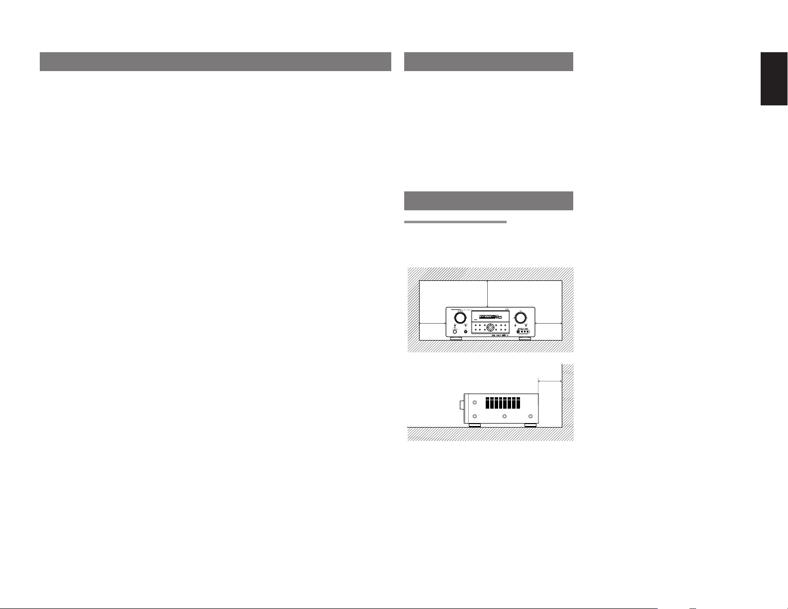
TABLE OF CONTENTS INTRODUCTION
SURROUND
DISPLAY
PURE
SETUP
DIRECT
SIMPLE
AUTO
HT-EQ
MENU
ENTER
MEMORY
CLEAR
T-MODE
EXIT
BAND
MODE
INTRODUCTION.................................. 1
PRECAUTIONS ................................... 1
DESCRIPTION..................................... 2
FEATURES .......................................... 3
ACCESSORIES ................................... 4
FRONT PANEL .................................... 5
FL DISPLAY ...................................................................... 6
REAR PANEL ...................................... 7
REMOTE CONTROL OPERATION ..... 8
FUNCTION AND OPERATION ......................................... 8
PROGRAMMING THE REMOTE CONTROLLER ............ 9
OPERATION OF REMOTE CONTROL UNIT ................. 10
GENERAL INFORMATION OF RC5500SR TO ZR6001 ..
CONNECTIONS................................. 12
CONNECTING FOR THE MULTI PLC LISTENING ........ 12
CONNECTING AN IR EMITTER (OTHER BRAND PRODUCT) ..
SPEAKER PLACEMENT ................................................ 13
CONNECTING SPEAKERS ............................................14
CONNECTING AUDIO COMPONENTS ......................... 15
CONNECTING VIDEO COMPONENTS ......................... 16
ADVANCED CONNECTING ........................................... 17
CONNECTING TO THE RC-5 (MARANTZ PRODUCTS ONLY) ..
CONNECTING THE ANTENNA TERMINALS .................18
CONNECTING FOR THE MULTI ROOM ........................19
SETUP ............................................... 20
ON SCREEN DISPLAY MENU SYSTEM ........................ 20
1 INPUT SETUP (ASSIGNABLE DIGITAL INPUT AND
COMPONENT VIDEO INPUT) ..................................... 21
2 SPEAKER SETUP ...................................................... 21
3 PREFERENCE ............................................................22
4 SURROUND ............................................................... 23
5 PL II (PRO LOGIC II)
MUSIC PARAMETER .................................................. 23
6 CS II (CIRCLE SURROUND II) PARAMETER .......... 23
7 MULTI ROOM..............................................................23
8 7.1 CH INPUT LEVEL ................................................. 24
9 MULTI PLC SETUP ..................................................... 24
10 SPEAKERS LEVEL SETTING WITHOUT TEST TONE ..
SIMPLE SETUP ................................. 26
BASIC OPERATION (PLAY BACK) .. 27
SELECTING AN INPUT SOURCE ..................................27
VIDEO CONVERT ........................................................... 27
SELECTING THE SURROUND MODE .......................... 27
ADJUSTING THE MAIN VOLUME .................................. 27
ADJUSTING THE TONE (BASS & TREBLE) CONTROL ...
TEMPORARILY TURNING OFF THE SOUND ............... 28
USING THE SLEEP TIMER ............................................ 28
NIGHT MODE ................................................................. 28
SURROUND MODE........................... 28
OTHER FUNCTION ........................... 31
TV AUTO ON/OFF FUNCTION....................................... 31
10
ATTENUATION TO ANALOG INPUT SIGNAL ................ 31
LISTENING THROUGH HEADPHONES ........................ 31
DOLBY HEADPHONE MODE ......................................... 31
VIDEO ON/OFF .............................................................. 31
13
DISPLAY MODE .............................................................. 31
SELECTING ANALOG AUDIO INPUT OR DIGITAL AUDIO INPUT
RECORDING AN ANALOG SOURCE ............................ 32
HT-EQ ............................................................................. 32
7.1 CH INPUT ................................................................. 32
AUX2 INPUT ................................................................... 33
17
LIP.SYNC ........................................................................33
BASIC OPERATION (TUNER) .......... 33
LISTENING TO THE TUNER .......................................... 33
PRESET MEMORY .........................................................34
MULTI ROOM SYSTEM ..................... 36
MULTI ROOM PLAYBACK USING THE MULTI ROOM
OUT TERMINALS ........................................................ 36
MULTI ROOM PLAYBACK USING THE MULTI SPEAKER
TERMINALS ................................................................. 36
MULTI PLC SYSTEM ......................................................36
TROUBLESHOOTING....................... 37
TECHNICAL SPECIFICATIONS ....... 38
DIMENSIONS .................................... 38
26
Thank you for purchasing the Marantz ZR6001
Surround receiver.
This remarkable component has been engineered
to provide you with many years of home theater
enjoyment. Please take a few minutes to read this
manual thoroughly before you connect and
operate the ZR6001.
As there are a number of connection and configuration
options, you are encouraged to discuss your own
27
particular home theater setup with your Marantz A/V
specialist dealer.
PRECAUTIONS
CAUTIONS ON INSTALLATION
For heat dispersal, leave at least 20 cm/8 inch of
space between the top, back and sides of this unit
and the wall or other components.
• Do not obstruct the ventilation holes.
SURROUND
MODE
AUTO
DISPMULTI AUTO TUNEDST V—OFFNIGHT PEAK ANALOG
SLEEP SURRAUTO DIRECT DISC 6.1MTX 6.1 SPKR BEQ
PURE
SIMPLE
SETUP
DIRECT
HT-EQ
MENU
20 cm (8 ins.)
SURROUND
ATT
DIGITAL
DIGITAL
LCR
LFE
AAC
PCM
SLS SR
DISPLAY
MEMORY
CLEAR
ENTER
T-MODE
EXIT
BAND
20 cm (8 ins.)
.. 32
ENGLISH
1
Page 5
ENGLISH
DESCRIPTION
DTS was introduced in 1994 to provide 5.1 channels
of discrete digital audio into home theater systems.
DTS brings you premium quality discrete
multichannel digital sound to both movies and music.
DTS is a multichannel sound system designed to
create full range digital sound reproduction.
The no compromise DTS digital process sets the
standard of quality for cinema sound by delivering
an exact copy of the studio master recordings to
neighborhood and home theaters.
Now, every moviegoer can hear the sound exactly
as the moviemaker intended.
DTS can be enjoyed in the home for either movies
or music on of DVD’s, LD’s, and CD’s.
“DTS” and “DTS Digital Surround” are registered
trademarks of Digital Theater Systems, Inc.
The advantages of discrete multichannel systems
over matrix are well known.
But even in homes equipped for discrete
multichannel, there remains a need for high-quality
matrix decoding. This is because of the large library
of matrix surround motion pictures available on disc
and on VHS tape; and analog television broadcasts.
The typical matrix decoder of today derives a
center channel and a mono surround channel from
two-channel matrix stereo material. It is better than
a simple matrix in that it includes steering logic to
improve separation, but because of its mono,
band-limited surround it can be disappointing to
users accustomed to discrete multichannel.
Neo:6 offers several important improvements as
follow,
• Neo:6 provides up to six full-band channels of
matrix decoding from stereo matrix material.
Users with 6.1 and 5.1 systems will derive six
and five separate channels, respectively,
corresponding to the standard home-theater
speaker layouts.
•
Neo:6 technology allows various sound elements
within a channel or channels to be steered
separately, and in a way which follows naturally
from the original presentation.
•
Neo:6 offers a music mode to expand stereo
nonmatrix recordings into the five- or six-channel
layout, in a way which does not diminish the subtlety
and integrity of the original stereo recording.
2
DTS-ES Extended Surround is a new multichannel
digital signal format developed by Digital Theater
Systems Inc. While offering high compatibility with
the conventional DTS Digital Surround format,
DTS-ES Extended Surround greatly improves the
360-degree surround impression and space
expression thanks to further expanded surround
signals. This format has been used professionally
in movie theaters since 1999.
In addition to the 5.1 surround channels (FL, FR, C,
SL, SR and LFE), DTS-ES Extended Surround
also offers the SB (Surround Back) channel for
surround playback with a total of 6.1 channels.
DTS-ES Extended Surround includes two signal
formats with different surround signal recording
methods, as DTS-ES Discrete 6.1 and DTS-ES
Matrix 6.1.
“DTS”, “DTS-ES” and “Neo:6” are trademarks of
Digital Theater Systems, Inc.
The stereo CD is a 16-bit medium with sampling at
44.1 kHz. Professional audio has been 20- or 24bit for some time, and there is increasing interest in
higher sampling rates both for recording and for
delivery into the home. Greater bit depths provide
extended dynamic range. Higher sampling rates
allow wider frequency response and the use of
anti-alias and reconstruction filters with more
favorable aural characteristics.
DTS 96/24 allows for 5.1channel sound tracks to
be encoded at a rate of 96kHz/24bits on DVDVideo titles.
When DVD-video appeared, it became possible to
deliver 24-bit, 96 kHz audio into the home, but only
in two channels, and with serious limitations on
picture. This capability has had little use.
DVD-audio allows 96/24 in six channels, but a new
player is needed, and only analog outputs are
provided, necessitating the use of the D/A
converters and analog electronics provided in the
player.
DTS 96/24 offers the following:
1. Sound quality transparent to the original 96/24
master.
2.
Full backward compatibility with all existing
decoders. (Existing decoders will output a 48 kHz
signal)
3.No new player required: DTS 96/24 can be
carried on DVD-video, or in the video zone of
DVD-audio, accessible to all DVD players.
4. 96/24 5.1-channel sound with full-quality fullmotion video, for music programs and motion
picture soundtracks on DVD-video.
“DTS” and “DTS 96/24” are trademarks of Digital
Theater Systems, Inc.
Dolby Digital identifies the use of Dolby Digital
audio coding for such consumer formats as DVD
and DTV. As with film sound, Dolby Digital can
provide up to five full-range channels for left,
center, and right screen channels, independent left
and right surround channels, and a sixth (“.1”)
channel for low-frequency effects.
Dolby Surround Pro Logic II is an improved matrix
decoding technology that provides better spatiality
and directionality on Dolby Surround program
material; provides a convincing three-dimensional
soundfield on conventional stereo music
recordings; and is ideally suited to bring the
surround experience to automotive sound. While
conventional surround programming is fully
compatible with Dolby Surround Pro Logic II
decoders, soundtracks will be able to be encoded
specifically to take full advantage of Pro Logic II
playback, including separate left and right
surround channels. (Such material is also
compatible with conventional Pro Logic decoders.)
Dolby Digital EX creates six full-bandwidth output
channels from 5.1-channel sources. This is done
using a matrix decoder that derives three surround
channels from the two in the original recording.
For best results, Dolby Digital EX should be used
with movies soundtracks recorded with Dolby
Digital Surround EX.
About Dolby Pro Logic
Dolby Pro Logic II x technology delivers a natural
and immersing 7.1-channel listening experience to
the home theater environment. A product of
Dolby’s expertise in surround sound and matrix
decoding technologies, Dolby Pro Logic II x is a
complete surround sound solution that maximizes
the entertainment experience from stereo as well
as 5.1-channel encoded sources.
II x
Dolby Pro Logic II x is fully compatible with Dolby
Surround Pro Logic technology and can optimally
decode the thousands of commercially available
Dolby Surround encoded video cassettes and
television programs with enhanced depth and
spatiality. It can also process any high-quality
stereo or Advanced Resolution 5.1-channel music
content into a seamless 6.1- or 7.1-channel
listening experience.
The Dolby Headphone technology provides a
surround sound listening experience over headphones.
When listening to multichannel content such as
DVD movies over headphones, the listening
experience is fundamentally different than
listening to speakers. Since the headphone
speaker drivers are covering the pinna of the ear,
the listening experience differs greatly from
traditional speaker playback. Dolby utilizes
patented headphone perspective curves to solve
this problem and provides a non-fatiguing,
immersive, home theater listening experience.
Dolby Headphone also delivers exceptional 3D
audio from stereo material.
Manufactured under license from Dolby
Laboratories. “Dolby”, “Pro Logic”, and the doubleD symbol are trademarks of Dolby Laboratories.
Circle Surround II (CS-II) is a powerful and
versatile multichannel technology. CS-II is
designed to enable up to 6.1 multichannel
surround sound playback from mono, stereo, CS
encoded sources and other matrix encoded
sources. In all cases the decoder extends it into 6
channels of surround audio and a LFE/subwoofer
signal. The CS-II decoder creates a listening
environment that places the listener “inside” music
performances and dramatically improves both hi-fi
audio conventional surround-encoded video
material. CS-II provides composite stereo rear
channels to greatly improve separation and image
positioning – adding a heightened sense of realism
to both audio and A/V productions.
Page 6
CS-II is packed with other useful feature like dialog
clarity (SRS Dialog) for movies and cinema-like
bass enrichment (TruBass). CS-II can enable the
dialog to become clearer and more discernable in
movies and it enables the bass frequencies
contained in the original programming to more
closely achieve low frequencies – overcoming the
low frequency limitations of the speakers by full
octave.
Circle Surround II , Dialog Clarity, TruBass, SRS
and
symbol are trademarks of SRS Labs,
Inc.
Circle Surround II , Dialog Clarity and TruBass
technology are incorporated under license from
SRS Labs, Inc.
HDCD® (High Definition Compatible Digital ®) is a
patented process for delivering on Compact Disc
the full richness and details of the original
microphone feed.
HDCD encoded CDs sound better because they
are encoded with 20-bits of real musical
information as compared to 16-bits for all other
CDs.
HDCD overcomes the limitation of the 16-bit CD
format by using a sophisticated system to encode
the additional four bits onto the CD while remaining
completely compatible with the CD format.
When listening to HDCD recordings, you hear
more dynamic range, a focused 3-D sound stage,
and extremely natural vocal and musical timbre.
With HDCD, you get the body, depth and emotion
of the original performance not a flat, digital
imitation.
HDCD system manufactured under license from
Microsoft. This product is covered by one or more
of the following: In the United States 5,479,168
5,638,074 5,640,161 5,808,574 5,838,274
5,854,600 5,864,311 5,872,531 and in Australia
669,114 with other patents pending.
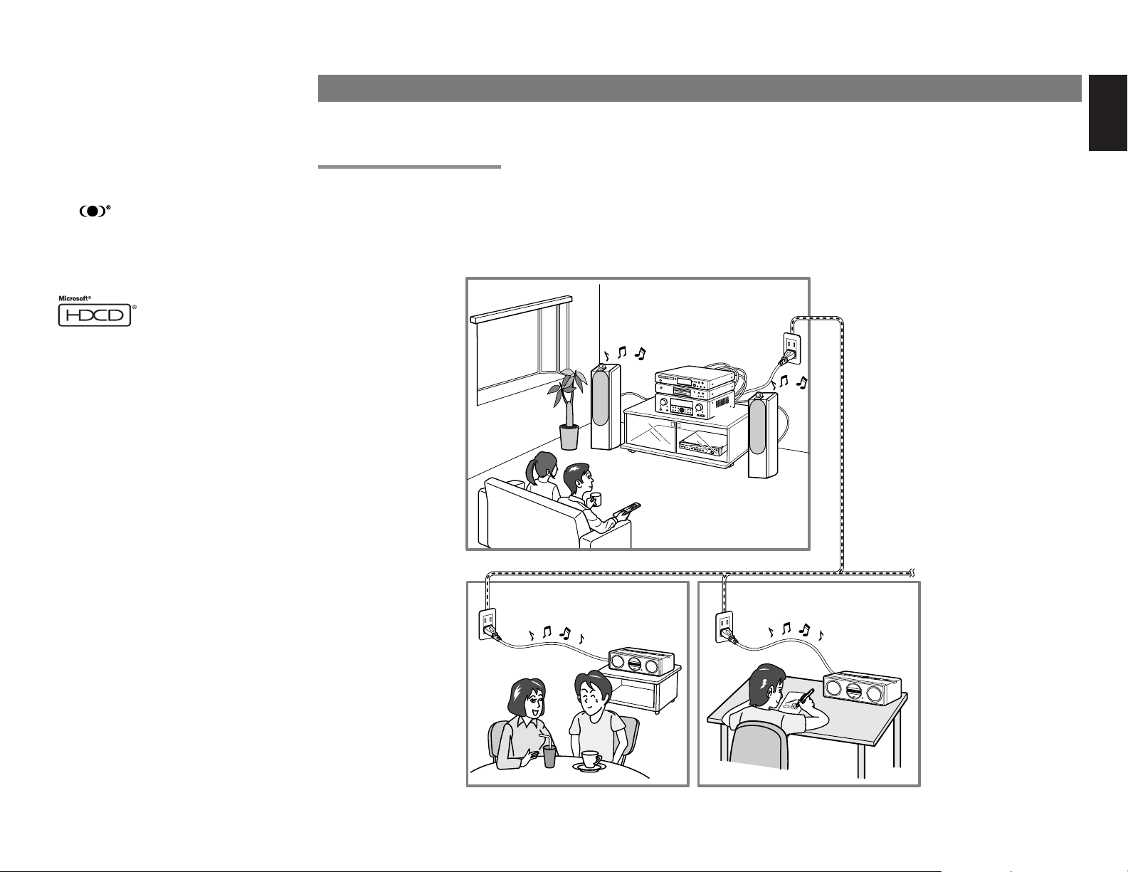
FEATURES
By simply plugging the power cables of the ZR6001 and ZC4001 into ordinary home electrical outlets, the ZR6001 sends audio sources over your home electrical
line for playback by the ZC4001.
PLC (POWER LINE COMMUNICATION)
The ZR6001* converts analog audio signals into noncompressed linear PCM digital signals, modulates them into high frequency signals, and sends them over
power lines. The ZC4001 demodulates the sent signals and converts them back to analog signals.
* If the condition of the power line degenerates because of the effects of noise from other devices or for other reasons, the ZR6001 uses an audio format of
different sampling rate and data bit length.
ROOM A
ZR6001
P
O
W
O
E
R
N
/
S
T
A
N
D
BY
P
H
O
N
E
S
SU
RR
O
U
N
D
M
O
DE
O
P
E
N
/
C
L
O
S
E
P
L
A
Y
ST
O
P
D
P
A
V
U
D
S
E
M
P
E
R
M
EV
O
R
V
.
Y
I
D
E
O
N
E
M
X
O
T
D
E
B
S
F
/
D
P
I
G
I
T
A
L
T
V
T
U
N
I
N
G
F
M
/
A
M
1
R
C
20
2
0
M
D
Home power line
ROOM B
ZC4001
ROOM C
ZC4001
ENGLISH
3
Page 7
ENGLISH
The ZR6001 incorporates the latest generation of
digital surround sound decoding technology such
as Dolby Digital EX, Dolby Digital, DTS-ES
(Discrete 6.1 and Matrix 6.1), DTS Neo:6 (Cinema,
Music), Dolby Pro-Logic II x (Movie, Music and
Game), Circle Surround II (Cinema and Music) .
In addition, Marantz has focused on the future. By
utilizing pre-out jacks, 7.1 direct inputs and a RS232C communication port, the ZR6001 is
tomorrow’s technology, today!
The ZR6001 features a fully discrete 7 channel
amplifier section capable of delivering 90 watts of
high-current amplification, for continuously clean
and stable power into each of the 7 channels. It
employs a massive EI power transformer in
combination with oversized filter capacitors.
Current feedback topology allows total operation
stability, while requiring minimal amounts of
negative feed-back, resulting in an excellent
transient frequency response and superb sonic
transparency. This design configuration is capable
of a clear and powerful reproduction of the most
demanding action movie soundtracks and full
range (multichannel) music discs. Through its
ability to generate very high output voltages, the
ZR6001 can easily drive the most demanding
speakers with optimum results.
The ZR6001 incorporates the most advanced
Digital Signal Processing circuitry, along with a
®
Crystal
192 kHz/24 bit D/A converter in each of
the 8 channels. Independent power supply circuits
are incorporated for the FL display, audio and
video sections for maximum separation, clarity
and dynamic range. Together with hand-selected
customized components, all elements work in
harmony to recreate the emotion, exactly as the
artist had intended.
The ZR6001 is designed and engineered with
extensive feedback from custom installation
experts, dealers and consumers. It features multiroom/multisource, a RS-232C communication
port, heavy duty speaker binding posts and an
extensive array of both analog and digital inputs /
outputs. With 4 assignable digital inputs, 2
assingnable component inputs, SACD Multi
Channel (7.1 channel) direct inputs video convert
system and OSD output versatility is taken to a
stunning new level. Furthermore, the ZR6001 can
output the OSD information through the Y/C (Svideo) and composite video outputs.
An easy-to-use universal remote control allows full
access to all of the operating functions and can be
used for system operation as well.
This unit has Simple Setup function for easy setup.
You can setup all speaker settings by just selecting
your room size and the number of your speakers
with Simple Setup function. You can also setup
customized settings just like conventional AV
amplifiers.
• Dolby Digital EX, Dolby Digital ,
DTS ES (Discrete 6.1, Matrix 6.1, Neo: 6)
• Dolby Headphone (DH1, DH2, DH3)
• Dolby Pro Logic II x (Movie, Music, Game)
• Circle Surround II (Movie, Music, Mono)
• HDCD decording
• 7 x 95 Watts (8 Ohm), Discrete Amplifiers
• High Power Current Feedback Circuitry
• Massive Energy Power Supply, Huge EI
Transformer, Large ELCO’s.
• 192 kHz/24 bit Crystal
®
DAC for all 8 Channels
• 32 bit Digital Surround Processing Chipsets
• Video Off Mode
• Large Heavy Duty Speaker Terminals for all
Channels
• RS-232C Terminal for System Control
• Set Up Menu via all Video Output (Composite,
S-Video and Component video)
• Auto Input Signal Detection
• Improved Station Name Input Method, 50
Presets
• Auto Adjust Function for Speaker Distance
Settings (Delay Time)
• Front AUX Input (Digital Camera, Portable DVD)
• Universal remote control
• Simple Setup Function
• Video convert system
• LIP.SYNC Funciton (Audio delay)
• PLC (Power Line Communication) function to
ZC4001.
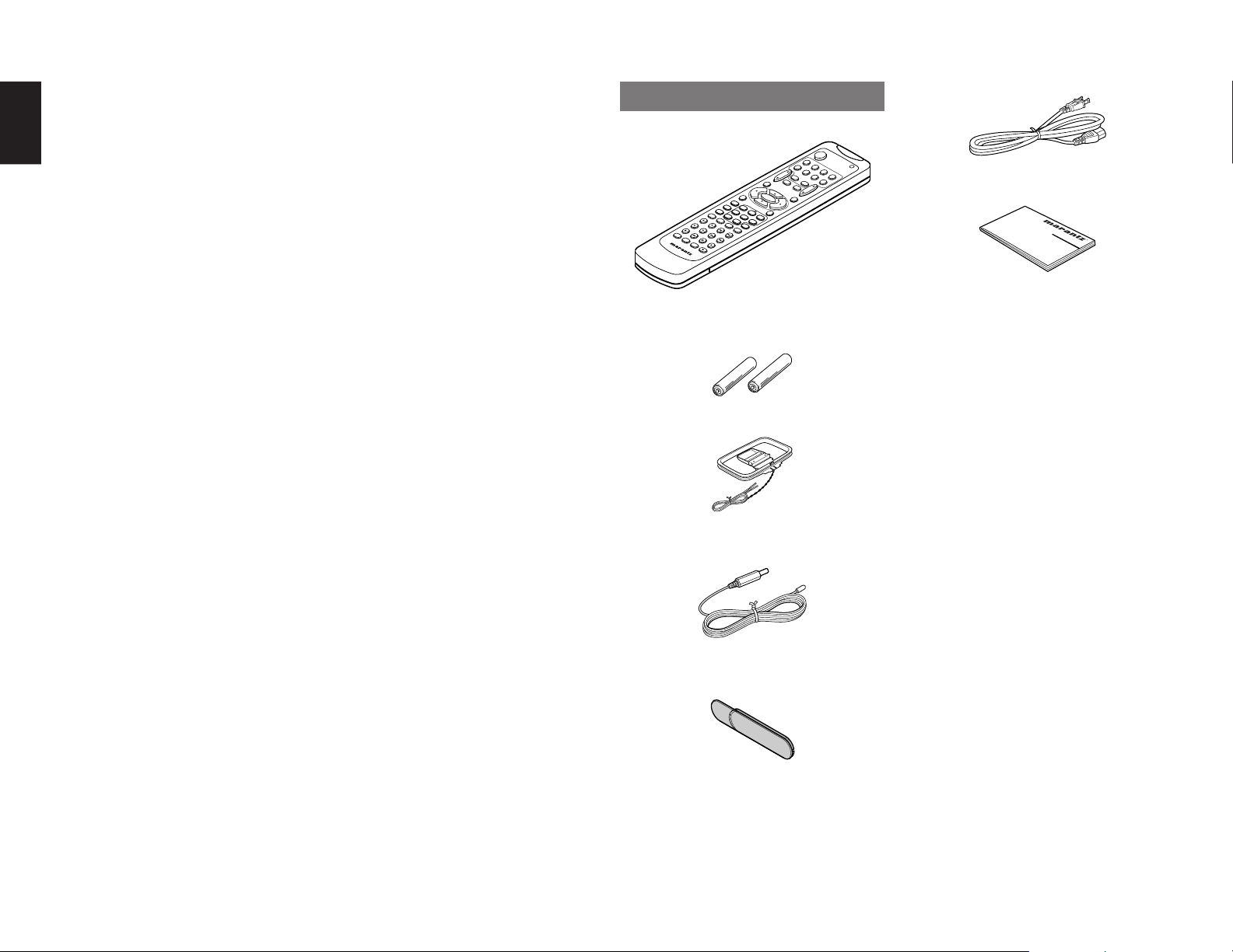
ACCESSORIES
Remote Controller RC5500SR
TUNER
TV
VOL.
A
U
X1
SLEEP
MUTE
O
S
D
ENTER
MENU
SETUP/
S
D
T
.TO
IR
E
N
C
E
T
NIG
AUTO
HT
ME
D
N
ISP
U
O
CSII EX/E
L
F
A
F
Y
4
21
CLEAR
M
C
H
-S
D
TS
7
T
S
3
S
MEMO
V
TER
IR
TU
EO
A
8
L
BASS
T-MODE
INPUT/DISC+
CH.SEL
A
U
D
IO
SUB-T/ATT
SYSTEM REMOTE CONTROLLER
RC5500SR
LIP.SYNC
AAA-size batteries X 2
AM Loop Antenna
FM Antenna
Front AUX Jack Cover
65
7.1C
A
/D
H
0
IN
9
P
.S
TR
C
C
A
E
H
N
B
A
/V
LE
N
-O
N
FF
E
L
/S
K
IP
T
U
N
E
/S
E
A
R
C
R
H
D
S
F
.D
IR
E
C
T
P
TY
P
P
U
U
S
S
H
H
AC Power Cord
POW
ER
T
V
VCR1
D
S
S
/
V
C
C
D
R
2
TAPE
DVD
C
D
R
/M
D
A
M
P
M
A
IN
VOL.
User Guide
4
Page 8
SURROUND
DISPLAY
PURE
SETUP
DIRECT
SIMPLE
AUTO
HT-EQ
MENU
ENTER
MEMORY
CLEAR
T-MODE
EXIT
BAND
MODE
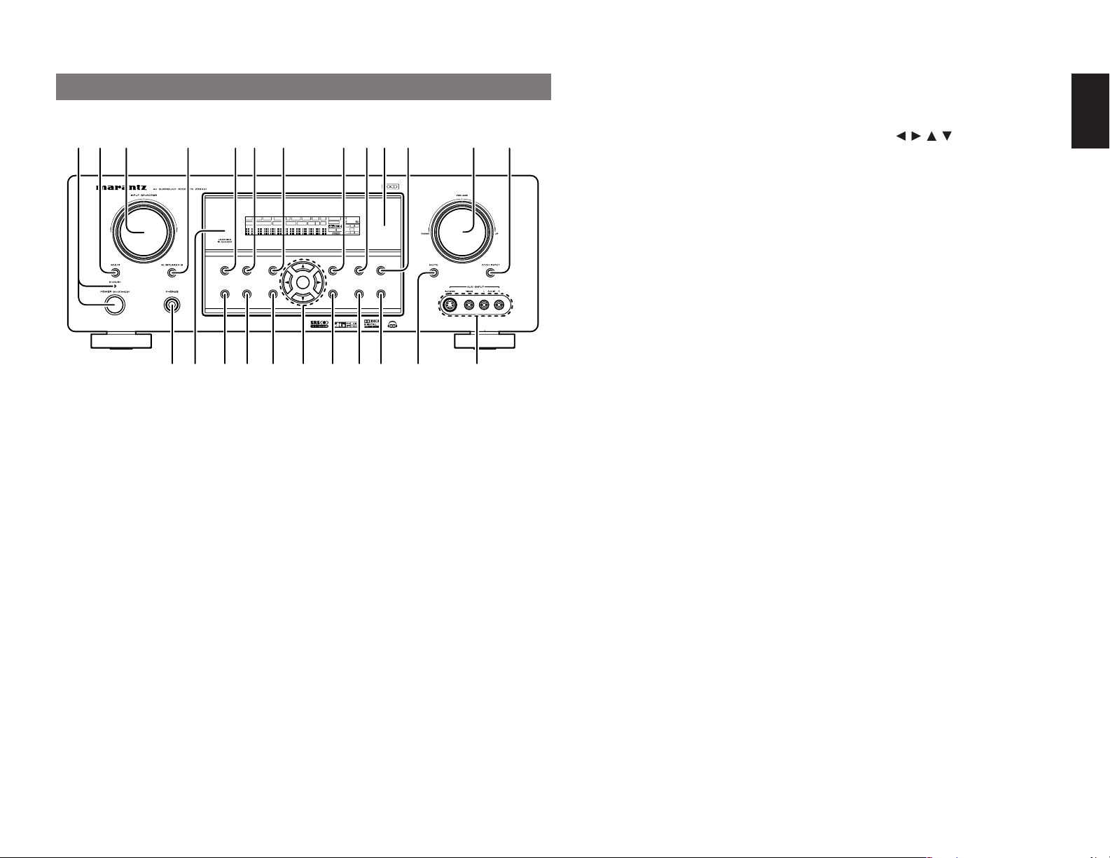
FRONT PANEL
qw ty !3uio !2!1re
DISP MULTI AUTO TUNED ST V—OFF NIGHT PEAK ANALOG
SURR
SLEEP
DIRECT DISC 6.1 MTX 6.1 SPKR B EQ
AUTO
SURROUND
PURE
SIMPLE
SETUP
DIRECT
MODE
AUTO
HT-EQ
MENU
q
POWER switch and STANDBY indicator
When this switch is pressed once, the unit turns ON
and the display illuminates. When pressed again,
the unit turns OFF and the STANDBY indicator will
be illuminated.
w
MULTI (Multi Room) button
Press this button to activate the Multiroom system.
“MULTI” indicator will be illuminated in the display.
e
INPUT SELECTOR knob (AUDIO/ VIDEO)
This knob is used to select the input sources.
The video function selector, such as TV, DVD, VCR1
and DSS, selects video and audio simultaneously.
Audio function sources such as CD, TAPE, CDR/
MD, and TUNER may be selected in conjunction
with a Video source.
This feature (Sound Injection) combines a sound
from one source with a picture from another.
Choose the video source first, and then choose a
different audio source to activate this function.
r
M.(Multi Room) SPEAKER B button
Press this button to activate the Multiroom Speaker
B system. “MULTI” indicator will be illuminated in
the display.
(See page 36)
!0
SURROUND
ATT
DIGITAL
DIGITAL
LCR
LFE
AAC
PCM
SL S SR
DISPLAY
MEMORY
CLEAR
ENTER
EXIT
t
You can select the surround mode by pressing this
button.
y
When this button is pressed, the tone control
circuitry is bypassed as well as Bass Management.
“DIRECT” indicator will be illuminated in the
display.
Notes:
• The surround mode is automatically switched to
• Additionally, Speaker Configurations are fixed
• This function is unavailable when the M. speaker
u
Press this button to enter the simple setup mode.
You can setup the speaker conditions (speaker
sizes, number of speakers, speaker delay times)
quickly by pressing the cursor buttons.
T-MODE
BAND
!6!7!8!9 !4@0@1@2@4
!5@3
SURROUND MODE button
PURE DIRECT button
AUTO when the pure direct function is turned on.
automatically as follows.
Front SPKR = Large, Center SPKR = Large,
Surround SPKR = Large, Sub woofer = On
B system is activated. While this function is
activated, this function will be canceled if the M.
SPEAKER B button is pressed.
SIMPLE SETUP button
i
DISPLAY button
When this button is pressed, the FL display mode
is changed as Surround Mode → Auto-display Off
→ Display Off → Input Function and the display off
indicator(DISP) lights up in condition of DISPLAY
OFF.
o
MEMORY button
Press this button to enter the tuner preset memory
numbers or station names. (See page 34)
!0
INFRARED receiving sensor window
This window receives infrared signals for the
remote control.
!1
CLEAR button
Press this button to cancel the station-memory
setting mode or preset scan tuning. (See page 34)
!2
VOLUME control knob
Adjusts the overall sound level. Turning the control
clockwise increases the sound level.
!3
7.1CH INPUT button
Press this button to select the output of an external
multichannel player.
!4
AUX1 INPUT jacks
These auxiliary video/audio input jacks accept the
connections of a camcorder, portable DVD, game
etc.
!5
MUTE button
Press this button to mute the output to the
speakers. Press it again to return to the previous
volume level.
!6
T-MODE button
Press this button to select the auto stereo mode or
mono mode when the FM band is selected.
The “AUTO” indicator lights in the auto stereo
mode. (See page 34)
!7
BAND button
Press this button to switch between FM and AM in
the TUNER mode.
!8
EXIT button
This button is used to exit from the SETUP MAIN
MENU.
!9
Cursor ( , , , ) / ENTER button
Use these buttons when operating the SETUP
MAIN MENU and TUNER function.
@0
MENU button
This button is used to enter the SETUP MAIN
MANU.
@1
HT-EQ button
Used to turn on or off HT(Home Theater)-EQ
mode. This mode compensates for the audio
portion of a movie sounding “bright”. When this
button is pressed, “EQ” indicator lights up.
@2
AUTO (Auto surround) button
Press this button to select the AUTO mode from the
surround modes. When this mode is selected, the
receiver determines the surround mode
corresponding to a digital input signal automatically.
@3
LEARNING IR SENSOR
This sensor is used to operate other brands from
the ZC4001 via the Multi PLC feature when the 4digit code of the source is not known.
@4
HEADPHONE jack for stereo headphones
This jack may be used to listen to the ZR6001’s
output through a pair of headphones. Be certain
that the headphones have a standard 1 / 4” stereo
phono plug. Note that the main room speakers will
automatically be turned off when the headphone
jack is in use.
Notes:
• When using headphones, the surround mode will
change to STEREO and Dolby Headphone by
MENU and Cursor button.
• The surround mode returns to the previous setting
as soon as the headphone plug is removed from
the jack.
ENGLISH
5
Page 9
ENGLISH
ND
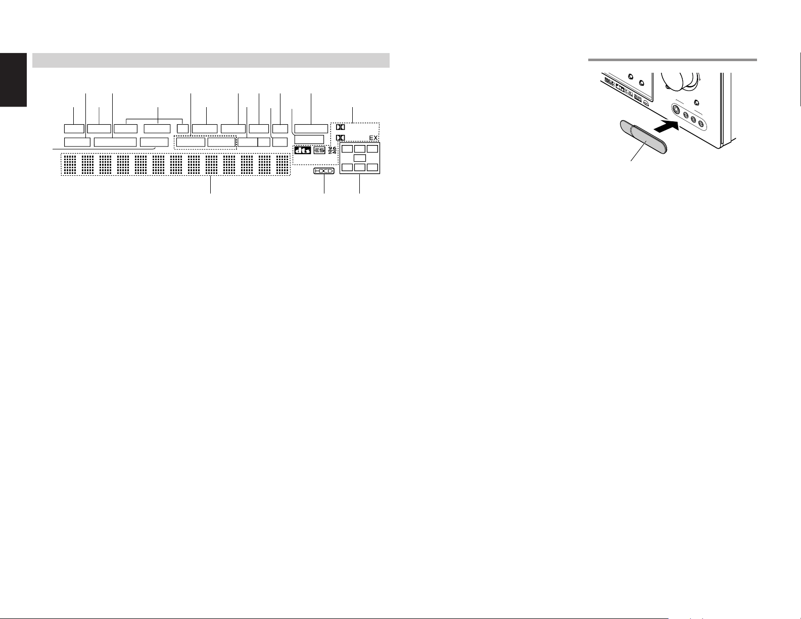
FL DISPLAY
s
a
DISP MULTI AUT O TUNED ST V–OFF NIGHT PEAK ANALOG
AUTO
SURR
SLEEP
g
DIRECT DISC 6.1 MTX 6.1 SPKR B EQ
¡8
DISP (Display Off) indicator
a
This indicator is illuminated when the ZR6001 is in
the display off condition.
s
SLEEP timer indicator
This indicator is illuminated when the sleep timer
function in the main-room is in use.
d
Multi-room system indicator
This indicator is illuminated when the multi-room
system is active.
f
AUTO SURR (Auto Surround mode)
indicator
This indicator is illuminated to show that the AUTO
SURROUND mode is in use.
g
TUNER’s indicators
AUTO : This indicator illuminates when the
TUNED : This indicator illuminates when a
ST(Stereo) : This indicator illuminates when an
tuner’s Auto mode is in use.
station is being received with
sufficient signal strength to provide
acceptable listening quality.
FM station is being tuned into
stereo condition.
h k¡0 ¡2 ¡4f
j l ¡1
¡7
j
V (video)-OFF mode indicator
This indicator is illuminated when the Video-OFF
function is active.
k
NIGHT mode indicator
This indicator is illuminated when the ZR6001 is in
the Night mode, which reduces the dynamic range
of digital program material at low volume levels.
l
SPKR (speaker) B indicator
This indicator is illuminated when the M (Multiroom)
speaker B system is active.
¡0
PEAK indicator
This indicator is a monitor for an analog audio input
signal. If the selected analog audio input signal is
greater than the capable level of internal
processing, this will illuminate. If this happens, you
should press the ATT button on the remote.
¡1
EQ mode indicator
This indicator is illuminated when the HT-EQ
function is active.
¡2
ATT (Attenuation) indicator
This indicator is illuminated when the attenuation
function is active.
ATT
¡3
DIGITAL
PCM
¡9
¡5d
SURROUND
DIGITAL
C
L
R
LFE
SL S SR
¡6
¡4
ANALOG input indicator
This indicator is illuminated when an analog input
source has been selected.
¡5
SIGNAL FORMAT indicators
2 DIGITAL, EX, 2 SURROUND, dts, ES, 96/24,
PCM
When the selected input is a digital source, some
of these indicators will be illuminated to display the
specific type of signal in use.
¡6
ENCODED CHANNEL STATUS
indicators
These indicators display the channels that are
encoded with a digital
input signal. If the selected digital input signal is
Dolby Digital 5.1ch or DTS 5.1ch, “L”, “C”, “R”,
“SL”, “SR” and “LFE” will be illuminated.If the
digital input signal is 2 channel PCM-audio, “L” and
“R” will be displayed.
If Dolby Digital 5.1ch signal with Surround EX flag
or DTS-ES signal comes in, “L”, “C”, “R”, “SL”, “S” ,
“SR” and “LFE” will be illuminated.
¡7
Main Information Display
This display shows messages relating to the
status, input source, surround mode, tuner,
volume level or other aspects of unit’s operation.
¡8
DIRECT (Puredirect) indicator
This indicator is illuminated when the ZR6001 is in
the PURE DIRECT mode.
¡9
HDCD indicator
When HDCD signal is decoded from digital input,
this indicator will light up.
HOW TO ATTACH THE FRONT AUX JACK COVER
T
-M
O
D
E
P
P
U
U
S
S
H
H
Front AUX Jack Cover
MUTE
S
V
ID
E
OV
UP
7
.1
C
H
IN
P
U
T
A
U
X
ID
1
I
E
N
O
P
U
T
L
A
U
D
I
O
R
h
DTS-ES mode indicators
(DISC6.1, MTX6.1)
These indicators will illuminate to show the DTSES decoding mode (Discrete 6.1 or Matrix 6.1).
6
¡3
DIGITAL Input Indicator
This indicator lights when a digital input has been
selected.
Page 10
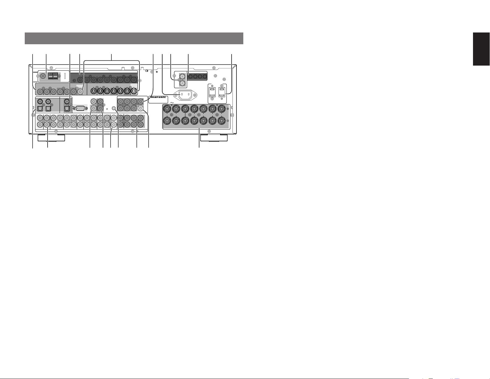
REAR PANEL
SPEAKER SYSTEMS : MINIMUM 6 OHMS
FRONT
CENTER
SURROUND
SURROUND BACK
M. SPEAKER B
MULTI
OUT
DVD
C
OUT
S-VIDEO
DVD
DSS/VCR2
C
RS-232C
RC
MULTI
OUT
DSS/VCR2
OUT
OUT
VCR1
VCR1
L
SBR
SBL
OUT
PRE
L
R
DSS/VCR2
DVDTVTV
R
IN
R
SW
RC-5
IN
SR
AUDIO
7.1CH
IN
OUT
IN
SL
SBR
SBL
CD
OUT
SW
OUT
CDR/MD
TAPE
OUTININ
OUT
VIDEO
MONITOR
VCR1
TV
OUT
(
AUX2
)
MONITOR
DIGITAL IN
DIGITAL OUT
3
1
OPT.
2
4
COAX.
L
R
L
SWITCHED
UNSWITCHED
1A 120W MAX
1A 120W MAX
FM
(
Ω
)
ANTENNA
GNDAMAM
COMPONENT VIDEO
C
B
/
P
B
C
R
/
P
R
C
R
/
P
R
C
R
/
P
R
C
B
/
P
B
C
B
/
P
B
INPUT-1
Y
Y
MONITOR OUT
INPUT-2
Y
OUT
AC OUTLETS
120V 60Hz
AC IN
IR EMITTER OUT
R
1
L
4
MULTI FIXED OUT
IN
FLASHER
MODEL NO. ZR6001
ANTENNA
(
)
FM
7575Ω
GND
VIDEO
TVTVDVD
VCR1
ININOUT
DIGITAL IN
DIGITAL OUT
3
1
L
R
COAX.
4
OPT.
2
VCR1
DVD
IN
OUT
!9 !8
q
VIDEO IN/OUT (TV, DVD, VCR1, DSS/VCR2)
These are the video inputs and outputs. There are
4 video inputs and 2 video outputs and each one
includes both composite video and S-video
configurations. Connect VCRs, DVD players, and
other video components to the video inputs.
The 2 video output channels can be used to be
connected to video tape recorders for making
recordings.
The input signals of video and S-video are
converted each other, and each of the converted
video signals can be output.
w
FM antenna terminal (75 ohms)
Connect an external FM antenna with a coaxial
cable, or a cable network FM source.
AM antenna and ground terminals
Connect the supplied AM loop antenna. Use the
terminals marked “AM” and “GND”. The supplied
AM loop antenna will provide good AM reception in
most areas. Position the loop antenna until you
hear the best reception.
e
RS-232C
The RS-232C port is to be used in conjunction with
an external controller to control the operation of the
ZR6001 by using an external device.
DSS/VCR2
ININOUT
DSS/VCR2
OUT
INPUT-1
C
B
Y
/
P
B
S-VIDEO
MONITOR
OUT
RS-232C
CD
TAPE
ININOUT
AUDIO
!7
tqw r yu
COMPONENT VIDEO
C
R
/
P
R
TV
MULTI
RC-5
Y
DVD
RC
CDR/MD
IN
INPUT-2
OUT
C
B
IN
OUT
/
P
B
VCR1
ININOUT
MONITOR OUT
C
R
/
FLASHER
IN
MULTI
OUT
C
R
C
B
Y
/
/
P
R
DSS/VCR2
ININOUT
R
LLSL
(
AUX2
P
P
B
MONITOR
OUT
SBL
SLSLL
SBR
SR
SBL
SBR
SRSRR
)
!6 !4!5 !3
!0eio
IR EMITTER OUT
R
C
MODEL NO. ZR6001
PRE
OUT
SW
C
7.1CH
IN
SW
!2
r
COMPONENT VIDEO INPUT/OUTPUT
If your DVD player or other device has component
video connectors, be sure to connect them to
these component video connectors on the
ZR6001. The ZR6001 has two component video
input connectors to obtain the color information (Y,
B
C
, CR) directly from the recorded DVD signal or
other video component and one component video
output connector to output it directly into the matrix
decoder of the display device.
By sending the pure DVD component video signal
directly, the DVD signal forgoes the extra
processing that normally would degrade the
image. The result is vastly increased image
quality, with incredibly life like colors and crisp
detail.
When the video convert function is enabled, video
and S-video images can be output to the
COMPONENT MOINTOR OUT jack.
t
MONITOR OUT
This is a monitor output and each one includes
both composite video and S-video configurations.
When connecting two video monitors or
televisions, be aware that the OSD interface can
be used with both MONITOR OUT connections.
y
Preamp Outputs
(L, R, SL, SR, SBL, SBR, C)
Jacks for L(front left), R (front right), C (Center), SL
(surround left), SR (surround right), SBL (surround
back left) and SBR (surround back right).
Use these jacks for connection to external power
amplifiers.
MULTI FIXED OUT
L
R
AC IN
RRL
FRONT
SPEAKER SYSTEMS : MINIMUM 6 OHMS
CENTER
1
22334
RRL
SURROUND
!1
AC OUTLETS
120V 60Hz
SWITCHED
1A 120W MAX
SURROUND BACK
M. SPEAKER B
UNSWITCHED
1A 120W MAX
LLR
u
AC INLET
Plug the supplied power cord into this AC INLET
and then into the power outlet on the wall.
ZR6001 can be powered by 120V AC only.
i
Multiroom Fixed OUTPUT
These are the audio output jacks for the Multi zone
(Multi room).
Volume is fixed and cannot be changed.
o
IR EMITTER OUT (1-4)
Connect to an IR emitter. These terminals output
remote control signals from the ZC4001 over the
power line to control sources via the Multi PLC
feature.
!0
AC OUTLETS
Connect the AC power cables of components such as
a DVD and CD player to these outlets. SWITCHED
and UNSWITCHED outlets are provided.
The one marked SWITCHED provides power only
when the ZR6001 is turned on and is useful for
components which you use every time you play
your system.
The one marked UNSWITCHED is always live as
long as the ZR6001 is plugged into a live outlet.
A component connected here may be left on
permanently, or may be switched off with via its
own power switch.
Caution:
•
In order to avoid potential turn-off thumps,
anything plugged into these outlets should be
powered up before the ZR6001 is turned on.
• The capacity of this AC outlet is 120W. Do not
connect devices that consume electricity more
than the capacity of these AC outlets. If the total
power consumption of the connected devices
exceeds the capacity, the protection circuit shuts
down the power supply.
!1
Speaker outputs terminals
Seven terminals are provided for the front left, front
right, front center, surround left, surround right,
surround back left and surround back right speakers.
Note:
• You can use surround back speaker terminals as
M (Multiroom) SPEAKER B terminals, when you
use no surround back speaker.
!2
Subwoofer Output
Connect this jack to the line level input of a powered
subwoofer. If an external subwoofer amplifier is used,
connect this jack to the subwoofer amplifier input. If
you are using two subwoofers, either powered or with
a 2 channel subwoofer amplifier, connect a “Y”
connector to the subwoofer output jack and run one
cable from it to each subwoofer amplifier.
!3
7.1 CHANNEL or AUX2 INPUT
By connecting a DVD Audio player, SACD
multichannel player, or other components that has
a multichannel port, you can playback the audio
with 5.1 channel or 7.1 channel outputs.
!4
FLASHER IN (Flasher input terminal)
These terminals are for controlling the unit from
each room using a keypad, etc.
!5
Multiroom Outputs (Audio L&R)
These are the audio output jacks for the Multi zone
(Multi room).
Connect these jacks to optional audio power
amplifiers to listen the source selected by the
multiroom system in a remote room.
!6
MULTI ROOM REMOTE IN/OUT terminals
IN: Connect to a multi-room remote control
device, available from your Marantz dealer.
OUT: Connect to the Marantz component
equipped with remote control (RC-5)
terminals in Multi zone (Multi room).
!7
REMOTE CONT. IN/OUT terminals
Connect to a Marantz component equipped with
remote control (RC-5) terminals.
!8
AUDIO IN/OUT (CD, TAPE, CD-R, TV,
DVD, VCR1, DSS/VCR2)
These are the analog audio inputs and outputs.
There are 7 audio inputs (4 of which are linked to
video inputs) and 4 audio outputs (2 of which are
linked to video outputs). The audio jacks are
nominally labeled for cassette tape decks,
compact disc players, DVD players and etc.... The
audio inputs and outputs require RCA-type
connectors.
!9
DIGITAL INPUT (Dig.1 - 4) / OUTPUT
(coaxial, optical)
These are the digital audio inputs and outputs.
There are 2 digital inputs with coaxial jacks, 2 with
optical jacks.
The inputs accept digital audio signals from a
compact disc, LD, DVD, or other digital source
component.
For digital output, there is 1 coaxial output and 1
optical output.
The digital outputs can be connected to MD
recorders, CD recorders, DAT decks, or other
similar components.
ENGLISH
7
Page 11
ENGLISH
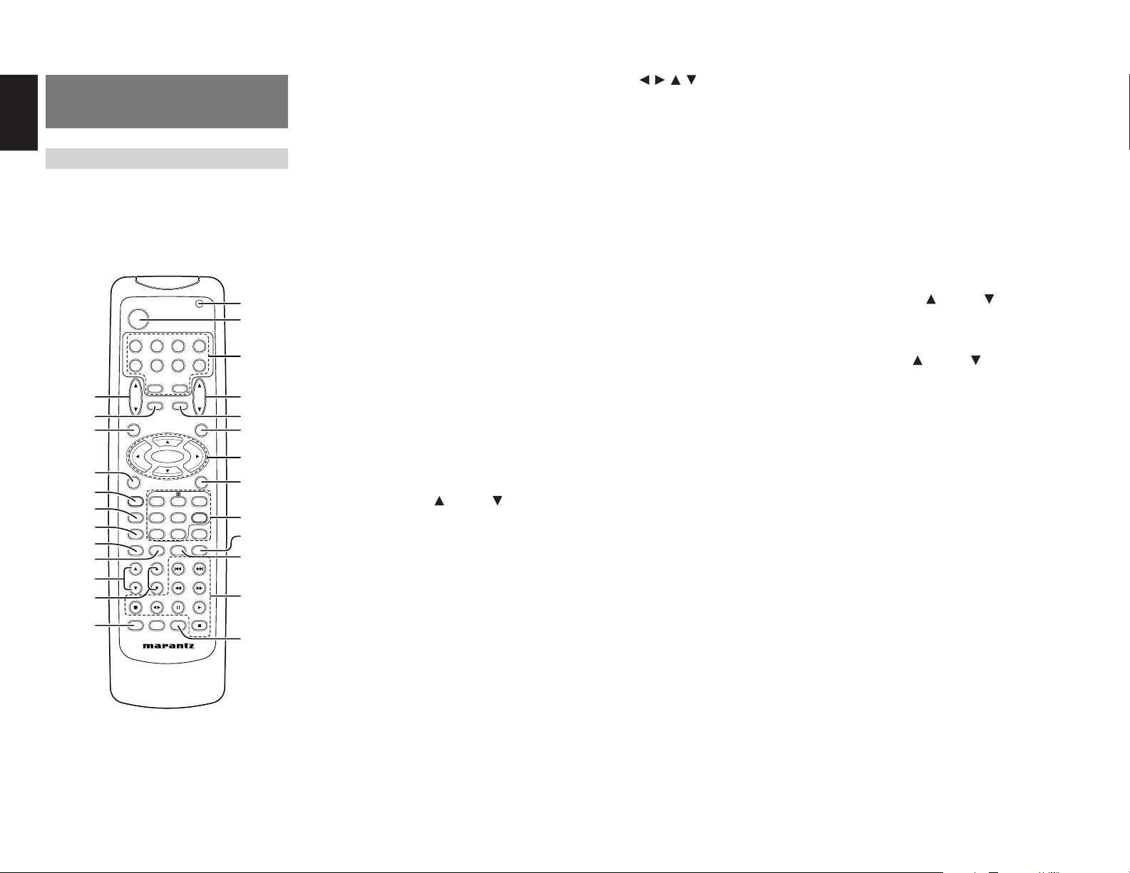
REMOTE CONTROL
OPERATION
FUNCTION AND OPERATION
The provided remote control unit is a universal
remote controller. The POWER button, numeric
buttons and control buttons are used in common
across different input source components.
The input source controlled with the remote control
unit changes when one of the input selector
buttons is pressed.
POWER
DVD
DSS/VCR2
CD
TAPE
CDR/MD
AMPAUX1
MAIN
VOL.
MUTE
MENU
ENTER
MENU OFF
DTS
RC5500SR
STEREO
A/D
CHANNEL/SKIP
TUNE/SEARCH
RDS
SUB-T/ATT
321
654
7.1CH IN
9807
P.SCAN/V-OFF
F.DIRECT
PTY
CSII EX/ES VIRTUAL
¤5
¤4
¤3
¤2
¤1
¤0
⁄9
⁄8
⁄7
⁄6
⁄5
⁄4
VCR1
TV
TUNER
TV
VOL.
SLEEP
OSD
SET UP/
T.TONE
PURE DIRECT
AUTO
NIGHT
MCH-ST
DISPLAY
MEMO
CLEAR
TREBLE
BASS
T-MODE
AUDIO
INPUT/DISC+
CH.SEL LIP.SYNC
SYSTEM REMOTE CONTROLLER
z
x
c
v
b
n
m
,
.
⁄0
⁄1
⁄2
⁄3
z
Transmitting indicator
Lights up during a button is pressed and an infrared
signal is sending.
x
(Main) POWER buttons
(when AMP mode is selected)
Press to switch the power of the ZR6001 ON or OFF
after pressing the AMP button.
c
Input selector buttons/ FUNCTION
SELECTOR buttons (AUDIO/VIDEO INPUT)
These buttons are used to select a Audio or Video
source component. Press one of these buttons once
to change the function of the remote control. Press
same button within 2 seconds, the input function of
the ZR6001 is changed.
Audio function sources such as CD, TAPE, CDR/
MD, and TUNER may be selected in conjunction
with a Video source.
This feature (Sound Injection) combines a sound
from one source with a picture from another.
Choose the video source first, and then choose a
different audio source to activate this function.
Notes:
• CDR/MD button is set CDR function at initial.
To switch MD function, press and hold down
CDR/MD button and press 2 button.
• To return CDR function, press and hold down
CDR/MD button and press 1 button.
v
MAIN VOLUME UP ( ) /DOWN ( ) buttons
Main volume control of the ZR6001. The front, surround, center and subwoofer channel volumes controlled by these buttons simultaneously.
b
MUTE button
Muting button of the ZR6001. Press this button decrease the sound temporarily. Press this button
again to return to the previous sound.
When this button is pressed, “MUTE” indicator lights
up.
n
MENU button
(when AMP mode is selected)
This button is used to enter the SETUP MAIN MENU.
m
Cursor ( , , , ) / ENTER buttons
(when AMP mode is selected)
Use these button when operating the SETUP MAIN
MENU.
,
MENU OFF button
(when AMP mode is selected)
This button is used to exit from the SETUP MAIN
MENU.
.
Numeric buttons 1 to 9 / Surround mode
buttons
Numeric buttons
These buttons are used to enter figures in the selection of a tuner preset station and station name preset or to set select a CD track number, etc. The functions of these buttons are dependent on the function
button selected.
Surround mode buttons
(when AMP mode is selected)
These buttons are used to select the surround mode.
⁄0
P.SCAN (Preset scan) / V(Video)-OFF
button
(when TUNER mode is selected)
This button is used to start preset scan when
ZR6001 is selected TUNER mode.
(when AMP mode is selected)
This is used when switching the video signals from
the various monitor outputs to Video-Off mode.
(See page 31)
⁄1
0 / A/D button
0 button
This button is used to enter the number “0”
A/D button (when AMP mode is selected)
This is used to switch between the analog and
digital inputs.
⁄2
CONTROL buttons
These buttons are used when operating the CD
player, TAPE deck, etc.
The function of these buttons are dependent on the
function button selected.
For the controllable functions of each input function,
please refer to controllable function table on the page
11.
⁄3
SUB-T (Title) / ATT (attenuator) button
When the input signal is too high and the voice distorts even while adjusting the ZR6001 VOLUME
control, turn on this function. “ATT ” is illuminated
when this function is activated.
The input level is reduced. Attenuator is invalid for
the output signal of “REC OUT”. (See page 31)
Note:
• This function is unavailable while the digital input
is selected.
⁄4
INPUT/DISC+ / CH.SEL buttons
This button is used to enter the input level setup
menu.
⁄5
TREBLE UP ( ) /DOWN ( ) buttons
These buttons are used to adjust the tone control of
high frequency sound for left and right speaker.
⁄6
BASS UP ( ) /DOWN ( ) buttons
These buttons are used to adjust the tone control of
low frequency sound for left, right and subwoofer
speaker.
⁄7
MEMO button
Memory enable button for various preset functions.
⁄8
CLEAR button
This button is used to cancel for certain memory or
programming operations.
⁄9
DISPLAY button
Selects the display mode for the front display of the
ZR6001.
¤0
NIGHT button
Pressing this button prevents the Dolby Digital signal from playback at a loud voice. This function reduces the voice by 1/3 to 1/4 at maximum. Thus, it
eliminates the occurrence of an abruptly loud voice
at night. However, the function is valid only in the
case when the Dolby Digital signal is entered into
OPTICAL or COAXIAL and data to compress the
voice exists in the signal to be played back.
When this button is pressed, the “NIGHT” indicator
is illuminated.
8
Page 12
ENTER
ENTER
TUNE/SEARCH
TREBLE
CHANNEL/SKIP
BASS
A/D
P.SCAN/V-OFF
7.1CH IN
STEREO
MCH-ST
MEMO
CLEAR
DISPLAY
NIGHT
CSII EX/ES VIRTUAL
DTS
PURE DIRECT
AUTO
321
654
9807
T.TONE
MENU OFF
SET UP/
2.
6.
3.
¤1
PURE DIRECT button
When this button is pressed, the tone control
circuit is bypassed.
¤2
SETUP / T.TONE button
(when AMP mode is selected)
Used to enter the test tone menu.
¤3
OSD button
(when AMP mode is selected)
When this button is pressed, the current setting is
displayed on the TV monitor.
¤4
SLEEP (sleep timer) button
This button is used for setting the sleep timer. It
can be operated the same way as the button on the
unit.
¤5
TV VOLUME UP ( ) /DOWN ( ) buttons
These buttons increase or decrease TV’s volume.
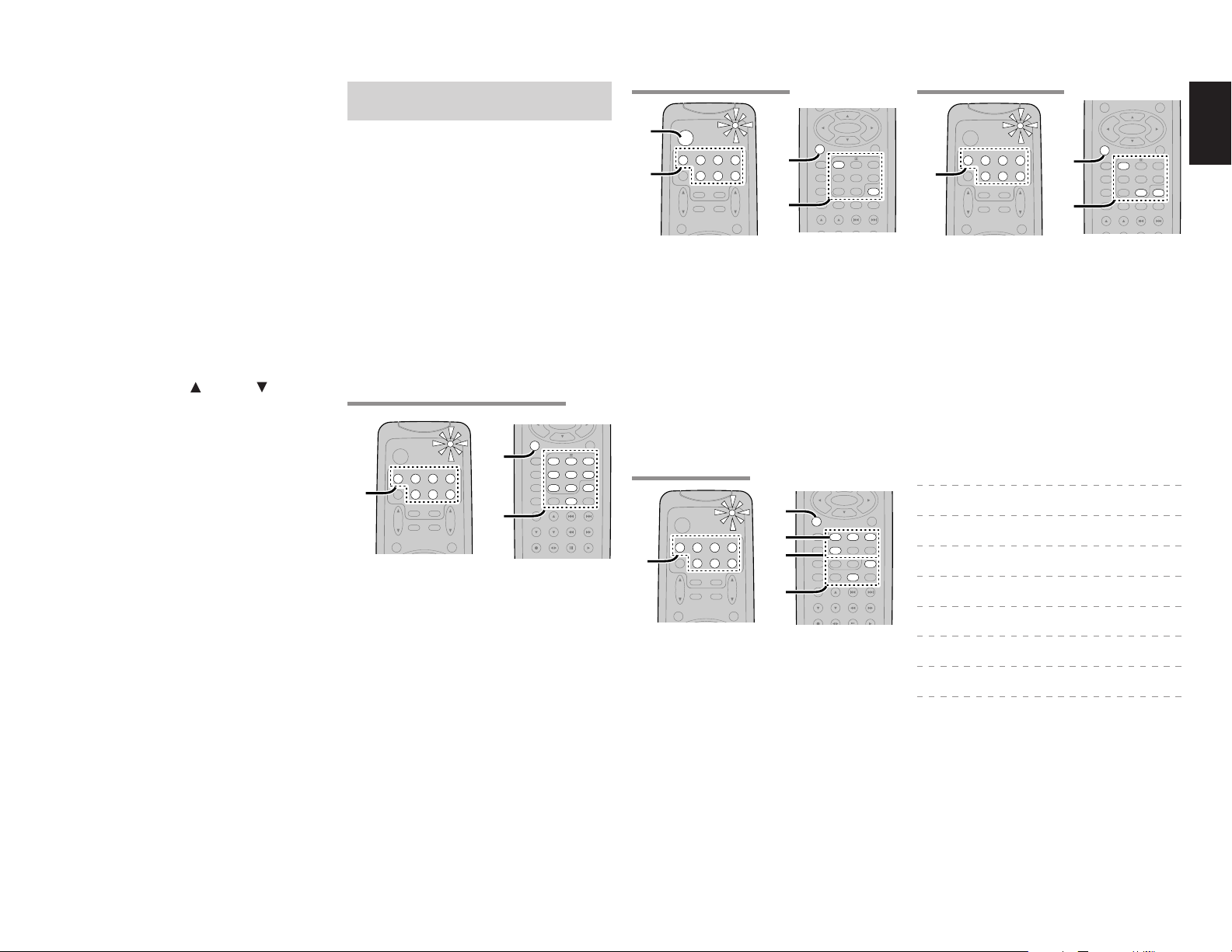
PROGRAMMING THE REMOTE
CONTROLLER
The remote controller RC5500SR must be
programmed to use the codes for your appliances
of different brands. This is done by keying in a 4digit code or by scanning the codes until the
correct one is found. We recommend to using the
4-digit code. This mode is faster and more reliable.
The code scanning method should be used only if
you cannot find the code for one of your
appliances. The codes are listed at the end of this
guide. (SET UP CODES FOR REMOTE
CONTROLLER RC5500SR)
Important:
•
Use the remote control buttons for programming,
not the buttons of the receiver or other appliances.
•
Some codes may be not match your equipment.
In this case, your equipment cannot be controlled
with this remote controller.
PROGRAMMING WITH THE 4-DIGIT CODE
POWER
1.
DVD
VCR1
DSS/VCR2
TV
1.
TUNERCDTAPE
TV
VOL.
1.
Press and hold down the Function Selector
CDR/MD
AMPAUX1
MAIN
VOL.
SLEEP
MUTE
MENU
OSD
2.
button for the appliance which should be
controlled and press SETUP button until the
indicator blinks twice.
2.
Press the 4-digit code for appliance (code
table at the end of this book)
3.
When the procedure is successful, the indicator
will blink twice.
Note:
• If the indicator did not blink twice, then repeat
steps 1 through 2 and try entering the same code
again.
PURE DIRECT
NIGHT
DISPLAY
CLEAR
BASS
INPUT/DISC+
SET UP/
T.TONE
AUTO
CSII EX/ES VIRTUAL
MCH-ST
MEMO
TREBLE
T-MODE
AUDIO
MENU OFF
STEREO
A/D
CHANNEL/SKIP
TUNE/SEARCH
RDS
SUB-T/ATT
DTS
321
654
7.1CH IN
9807
P.SCAN/V-OFF
F.DIRECT
PTY
SCANNING THE CODE TABLE
4.
2.
4.
1.
2.
3.
4.
5.
6.
POWER
DVD
VCR1
DSS/VCR2
TV
TUNERCDTAPE
TV
VOL.
CDR/MD
AMP
AUX1
MAIN
VOL.
SLEEP
MUTE
MENU
OSD
Switch on the appliance which should be
controlled.
Press and hold down the Function Selector
button for appliance which should be
controlled and press SETUP button until the
indicator blinking twice.
Press the code 9 - 9 - 1.
The indicator will blink twice.
Aim the remote control at the appliance and
slowly alternate between pressing POWER
button and the
Function Selector
the appliance.
Stop when the appliance turns off.
Press SETUP button once to lock in the code.
CHECKING THE CODE
PURE DIRECT
NIGHT
DISPLAY
CLEAR
BASS
ENTER
SET UP/
T.TONE
AUTO
CSII EX/ES VIRTUAL
MCH-ST
MEMO
TREBLE
T-MODE
POWER
VCR1
DSS/VCR2
TV
TUNERCDTAPE
1.
1.
Press and hold down the Function Selector
AMP
AUX1
TV
VOL.
SLEEP
MUTE
MENU
OSD
CDR/MD
1.
DVD
3.
4.
MAIN
VOL.
2.
button for appliance which should be
controlled and press SETUP button until the
indicator blinking twice.
2.
Press the code 9 - 9 - 0.
The indicator will blink twice.
3.
To view the code for first digit, press 1 once.
Wait 3 seconds, count the indicator blinks
(e.g. 3 blinks = 3) and write down the number.
Note:
• If a code digit is “0”, the indicator will not blink.
4.
Repeat step 3 three more times for remaining
digits. Use 2 for the second digit, 3 for the
third digit, and 4 for the fourth digit.
button for
MENU OFF
DTS
321
654
7.1CH IN
STEREO
9807
A/D
P.SCAN/V-OFF
CHANNEL/SKIP
TUNE/SEARCH
F.DIRECT
RDS
RESETTING THE ALL CODE
MENU
OSD
POWER
DVD
VCR1
DSS/VCR2
TV
TUNERCDTAPE
1.
1.
Press and hold down the any Function
AMP
AUX1
TV
VOL.
SLEEP
MUTE
MENU
OSD
CDR/MD
1.
MAIN
VOL.
2.
PURE DIRECT
NIGHT
DISPLAY
CLEAR
BASS
ENTER
SET UP/
T.TONE
AUTO
CSII EX/ES VIRTUAL
MCH-ST
MEMO
TREBLE
MENU OFF
STEREO
A/D
CHANNEL/SKIP
TUNE/SEARCH
DTS
321
654
7.1CH IN
9807
P.SCAN/V-OFF
Selector button and press SETUP button until
the indicator blinking twice.
2.
Press the code 9 - 8 - 1.
The indicator will blink twice.
Then, RC5500SR will return to the factory
preset code.
Note:
• After this procedure, the selected function button
is set initial code and other function buttons are
set initial code too.
Once you have found and the codes for your various
appliances, you may want to write them down here.
TV
VCR
DSS
DVD
CD
TAPE
CDR
MD
ENGLISH
9
Page 13
ENGLISH
CH.SEL LIP.SYNC
PTY
SUB-T/ATT
AUDIO
INPUT/DISC+
F.DIRECT
RDS
TUNE/SEARCH
T-MODE
TREBLE
CHANNEL/SKIP
BASS
A/D
P.SCAN/V-OFF
7.1CH IN
STEREO
MCH-ST
MEMO
CLEAR
DISPLAY
NIGHT
CSII EX/ES VIRTUAL
DTS
PURE DIRECT
AUTO
321
654
9807
T.TONE
MENU OFF
SET UP/
MENU
OSD
VOL.
TV
SLEEP
MUTE
AMP
TUNERCDTAPE
CDR/MD
DVD
POWER
VCR1
DSS/VCR2
TV
SYSTEM REMOTE CONTROLLER
RC5500SR
VOL.
MAIN
ENTER
AUX1
ENTER
CH.SEL LIP.SYNC
PTY
SUB-T/ATT
AUDIO
INPUT/DISC+
F.DIRECT
RDS
TUNE/SEARCH
T-MODE
TREBLE
CHANNEL/SKIP
BASS
A/D
P.SCAN/V-OFF
7.1CH IN
STEREO
MCH-ST
MEMO
CLEAR
DISPLAY
NIGHT
CSII EX/ES VIRTUAL
DTS
PURE DIRECT
AUTO
321
654
9807
T.TONE
MENU OFF
SET UP/
MENU
OSD
VOL.
TV
VOL.
MAIN
SLEEP
MUTE
AMP
TUNERCDTAPE
CDR/MD
DVD
POWER
VCR1
DSS/VCR2
TV
SYSTEM REMOTE CONTROLLER
RC5500SR
AUX1
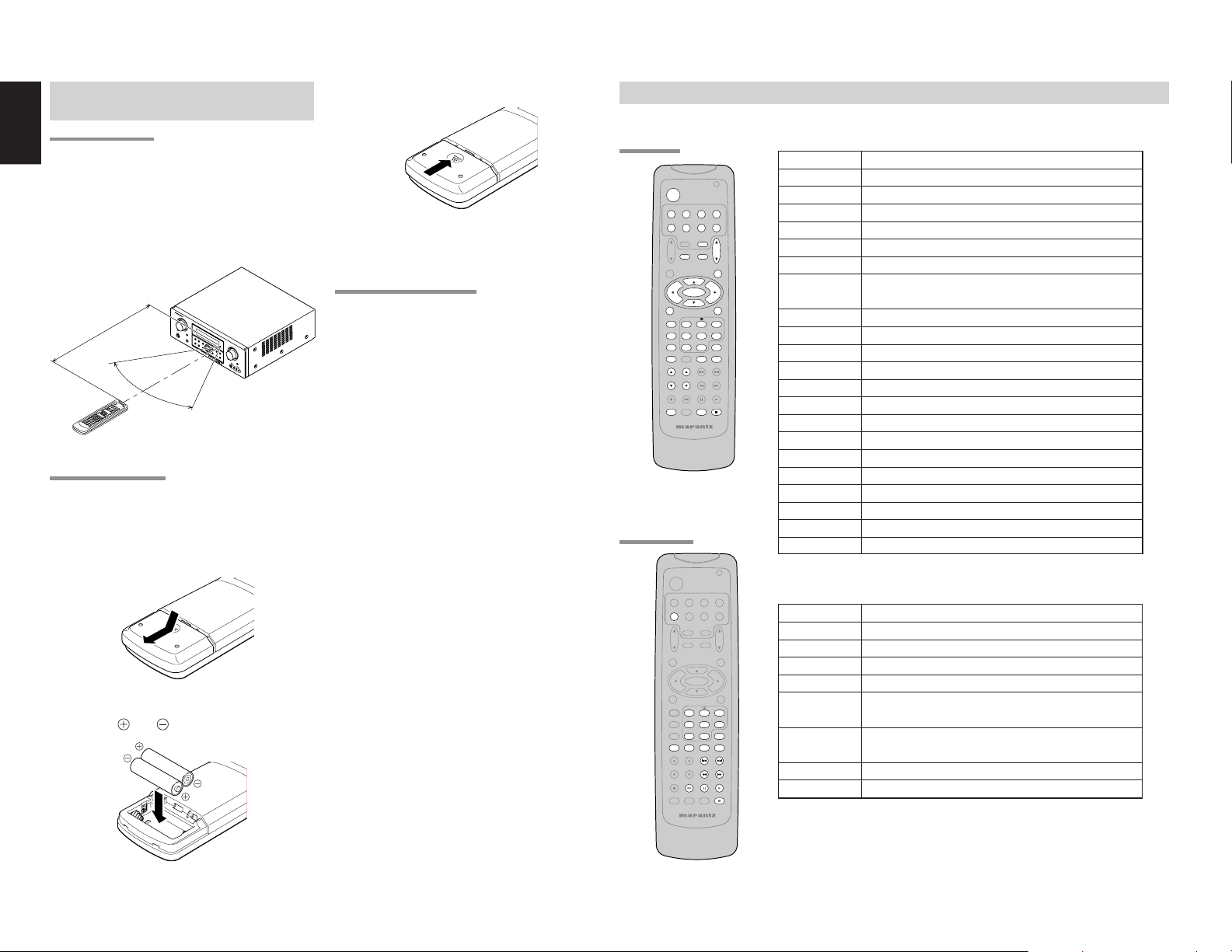
OPERATION OF REMOTE CONTROL
UNIT
REMOTE CONTROL
The distance between the transmitter of the
remote control and the IR SENSOR of the ZR6001
should be less than 5 meters. If the remote control
is pointed in a direction other than the IR SENSOR
or if there is an obstacle between them, use of the
remote control may not be possible.
Remote-controllable range
I
N
P
U
T
S
E
A
L
VSU
E
C
T
R
O
R
R
O
U
N
D
R
E
C
E
I
VER
Z
R
6
0
0
1
M
U
L
T
I
ST
AN
D
BY
P
O
W
M
E
.
R
S
P
O
E
N
A
/
O
K
F
E
F
R
B
S
U
R
R
O
M
U
O
N
P
D
D
H
E
O
N
E
S
P
U
R
D
E
I
R
E
C
T
S
I
M
P
A
S
L
E
U
E
T
T
U
O
P
Approx. 5 m
60°
Remote control unit (RC5500SR)
LOADING BATTERIES
The life of the batteries used with the remote
control is about 4 months with normal use. Also be
sure to replace batteries earlier when you notice
that they are getting weak.
1.
Remove the back cover.
2.
Insert the new batteries (AAA type) with
10
correct
and polarity.
H
T
-
E
Q
M
E
N
U
D
I
S
P
L
A
Y
E
N
TE
R
M
E
M
O
R
D
Y
O
W
N
C
E
L
X
E
I
T
A
R
B
A
N
D
T
-
M
O
D
E
M
U
T
E
3.
Close the cover until it clicks.
GENERAL INFORMATION OF RC5500SR TO ZR6001
To control the ZR6001 by your RC5500SR, you have to select the device AMP or TUNER by pressing the
function selector button. Please refer below for the details in AMP and TUNER mode.
AMP MODE
POWER Turns the ZR6001 on and off
Function selector *
SLEEP * Sets the sleep timer function
Notes:
• Do not mix alkaline and manganese batteries.
• Do not mix old and new batteries.
ZR6001
CAUTIONS ON BATTERIES
MUTE * Decreases the sound temporarily
VOL34 * Adjusts the over all sound level
MENU Enters the SETUP MENU
Cursor Moves the cursor for settings in the SETUP MENU
ENTER • Enters the SETUP MENU
• Use “AAA” type batteries in this remote control
unit.
V
O
L
U
M
E
UP
7
.
1
C
H
I
N
P
S
UT
V
I
D
E
O
A
U
X
V
I
1
D
I
E
N
OL
P
U
T
A
U
D
I
O
R
• If the remote control unit does not operate from
close to the main unit, replace the batteries with
new ones, even if less then a year has passed.
• The included battery is only for verifying
operation. Replace it with a new battery as soon
as possible.
• When inserting the batteries, be careful to do so
in the proper direction, following the + and marks in the remote control unit’s battery
compartment.
• To prevent damage or battery fluid leakage:
- Do not use a new battery with an old one.
- Do not use two different types of batteries.
- Do not short-circuit, disassemble, heat or
dispose of batteries in flames.
TUNER MODE
• Remove the batteries when not planning to use
the remote control unit for a long period of time.
SETUP/T.TONE Enters the test tone mode for setting the Speaker Level Setup
MENU OFF Exits from the SETUP MENU
PURE DIRECT * Selects the Pure Direct mode
NIGHT * Turns on or off the NIGHT mode
DISPLAY * Change the front display mode
Surround mode (1-8)
7.1CH-IN (9) Selects the 7.1CH IN
A/D (0) Switches between the analog and digital inputs
BASS34 * Adjusts the tone control of low frequency sound
TREBLE34 * Adjusts the tone control of high frequency sound
SUB-T/ATT Reduces the input level
P.SCAN/V-OFF Turns on or off the Video output
CH. SEL Adjusts the input level
LIP.SYNC Selects the LIP. SYNC mode
* These buttons are used to control ZR6001 in any function mode.
• If the batteries should leak, carefully wipe off the
fluid from the inside of the battery compartment,
then insert new batteries.
• When disposing of used batteries, please
comply with governmental regulations or
environmental public instruction’s rules that
apply in your country or area.
TUNER Selects a frequency band
0-9 Inputs the numeric #s
CLEAR Clears the inputting
MEMO Enters the tuner preset memory numbers
P.SCAN/V-OFF Starts preset scan
CHANNEL/SKIP • Selects a preset station
4
/
¢
TUNE/SEARCH Tunes a station
5
/
6
T-MODE
F.DIRECT
Selects a particular source component
• Confirms the settings in SETUP MENU
Selects the surround mode
1 2
Selects the auto stereo mode or mono mode
2
Selects the “Frequency direct input”
Page 14
THE CONTRABLE FUNCTION TABLE
POWER
VCR1
DSS/VCR2
TV
TUNERCDTAPE
AMP
AUX1
TV
VOL.
SLEEP
MUTE
MENU
OSD
ENTER
SET UP/
MENU OFF
T.TONE
PURE DIRECT
AUTO
NIGHT
CSII EX/ES VIRTUAL
STEREO
MCH-ST
DISPLAY
A/D
MEMO
CLEAR
CHANNEL/SKIP
TREBLE
BASS
TUNE/SEARCH
RDS
T-MODE
SUB-T/ATT
AUDIO
INPUT/DISC+
CH.SEL LIP.SYNC
SYSTEM REMOTE CONTROLLER
RC5500SR
DVD
CDR/MD
MAIN
VOL.
DTS
321
654
7.1CH IN
9807
P.SCAN/V-OFF
F.DIRECT
PTY
TV VCR DVD DSS CD TAPE CDR MD
POWER POWER POWER POWER POWER POWER POWER POWER POWER
MENU
CALL UP CALL UP CALL UP CALL UP SWITCH SWITCH SWITCH SWITCH
MENU MENU MENU MENU DISPLAY DISPLAY DISPLAY DISPLAY
Cursor Cursor Cursor Cursor Cursor – – – –
ENTER OK OK OK OK – – – –
SETUP/T.TONE – –
MENU OFF –
0 - 9
CLEAR
INPUT INPUT INPUT INPUT INPUT INPUT INPUT INPUT
NUMERIC NUMERIC NUMERIC NUMERIC NUMERIC NUMERIC NUMERIC NUMERIC
INPUT TAPE INPUT INPUT INPUT INPUT INPUT INPUT
CLEAR SPEED CLEAR CLEAR CLEAR CLEAR CLEAR CLEAR
CANCEL
MENU MENU
MEMO – –
SETUP
MENU
–
CALL
PROGRAM PROGRAM PROGRAM PROGRAM PROGRAM
–––––
CANCEL
–
––––
CALL CALL CALL CALL
CHANNEL/SKIP4CH– PREV PREV CH– PREV PREV PREV PREV
CHANNEL/SKIP¢CH+ NEXT NEXT CH+ NEXT NEXT NEXT NEXT
TUNE/SEARCH5– REWIND REWIND – REWIND REWIND REWIND REWIND
TUNE/SEARCH6– FF FF – FF FF FF FF
0
(REC) – REC – – – REC REC REC
T-MODE
1 2
RDS
;
F.DIRECT
2
– – – – – DIRECTION – –
– PAUSE PAUSE – PAUSE PAUSE PAUSE PAUSE
– PLAY PLAY – PLAY PLAY PLAY PLAY
INPUT/DISC+ INPUT SEL. TV/VCR DISC+ TV/DSS DISC+ – DISC+ –
AUDIO – AUDIO AUDIO AUDIO – – – –
PTY
9
– STOP STOP – STOP STOP STOP STOP
SUB-T/ATT – – SUBTITLE – – – – –
ENGLISH
11
Page 15
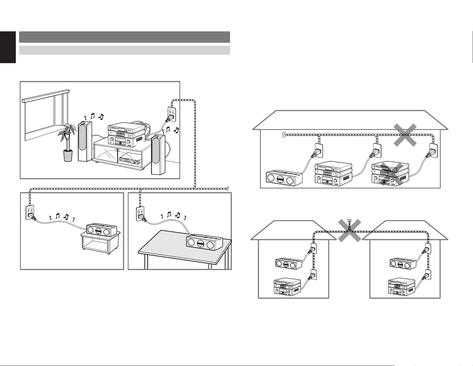
ENGLISH
CONNECTIONS
CONNECTING FOR THE MULTI PLC LISTENING
Connect the AC power cable of the ZR6001 to a wall electrical outlet. Also connect the AC power cable of
the ZC4001 to a wall electrical outlet.
Up to four ZC4001 units may be connected to the same system at one time.
ROOM A
ZR6001
P
O
W
O
E
R
N
/
S
T
A
N
D
B
Y
P
H
O
N
E
S
S
U
R
R
O
U
N
D
M
O
D
E
O
P
E
N
/
C
L
O
S
E
P
L
AY
S
T
O
P
D
P
A
V
U
D
S
E
M
P
E
R
M
E
O
V
R
V
.
Y
I
D
E
O
N
E
MO
X
T
DE
B
S
F
/
D
P
I
G
I
T
A
L
T
V
T
U
N
I
N
G
F
M
/
A
M
1
Notes:
• The ZR6001 sends audio data to the ZC4001 over power lines. Therefore, if the condition of the power line
degenerates seriously because of the effects of noise from other devices or for other reasons, audio data may
not be received or may skip.
• If the distance of the power line between the ZR6001 and ZC4001 is very long, audio data may not be received
or may skip.
• At the time of purchase, all ZC4001 and ZR6001 are set to the same Group ID. If used with this same Group
ID, you risk having your music listened into by others. Therefore, set the Group ID as explained herein.
• If the following trouble is experienced, block PLC signals from other sources using a commercially available
power filter, etc.
When a ZC4001 and ZR6001 are connected over PLC, another ZR6001 cannot be added to the same power
line and connected over PLC. In this case, PLC signals are not sent.
ZC4001
ZC4001
12
Home power line
ROOM B ROOM C
ZC4001
ZC4001
ZR6001
If a ZR6001 and ZC4001 are connected over PLC in a nearby apartment unit for example, and there is only
a short distance between your apartment and your neighbor’s, the PLC signals from your neighbor’s
apartment can travel over power lines to your place, mix with your system, and prevent audio output.
ZR6001
ZC4001 ZC4001
ZR6001ZR6001
Page 16
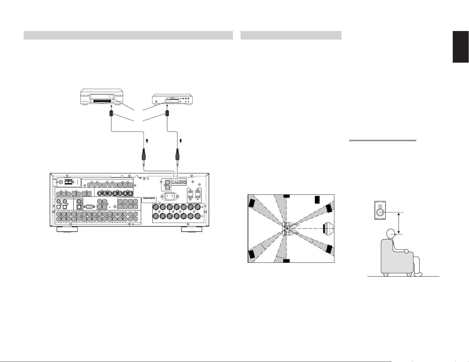
CONNECTING AN IR EMITTER (OTHER BRAND PRODUCT)
SPEAKER SYSTEMS : MINIMUM 6 OHMS
FRONT
CENTER
SURROUND
SURROUND BACK
M. SPEAKER B
MULTI
OUT
DVD
C
OUT
S-VIDEO
DVD
DSS/VCR2
C
RS-232C
RC
MULTI
OUT
DSS/VCR2
OUT
OUT
VCR1
VCR1
L
SBR
SBL
OUT
PRE
L
R
DSS/VCR2
DVDTVTV
R
IN
R
SW
RC-5
IN
SR
AUDIO
7.1CH
IN
OUT
IN
SL
SBR
SBL
CD
OUT
SW
OUT
CDR/MD
TAPE
OUTININ
OUT
VIDEO
MONITOR
VCR1
TV
OUT
(
AUX2
)
MONITOR
DIGITAL IN
DIGITAL OUT
3
1
OPT.
2
4
COAX.
L
R
L
SWITCHED
UNSWITCHED
1A 120W MAX
1A 120W MAX
FM
(
Ω
)
ANTENNA
GNDAMAM
COMPONENT VIDEO
C
B
/
P
B
C
R
/
P
R
C
R
/
P
R
C
R
/
P
R
C
B
/
P
B
C
B
/
P
B
INPUT-1
Y
Y
MONITOR OUT
INPUT-2
Y
OUT
AC OUTLETS
120V 60Hz
AC IN
IR EMITTER OUT
R
1
L
4
MULTI FIXED OUT
IN
FLASHER
MODEL NO. ZR6001
When the ZR6001 and ZC4001 are connected via the PLC, the ZC4001 can control other brand product.
Other brand product is controlled by remote control signals sent from an emitter connected to the IR
EMITTER OUT terminals of the ZR6001 to the IR sensor of the source unit.
To control other brand’s output, an IR code must be set. If the IR code of the source is unknown, the IR
code learning feature must be used.
OTHER BRAND VCR
OTHER BRAND DVD PLAYER
IR SENSOR
EMITTER
IR OUTPUT
SPEAKER PLACEMENT
The ideal surround speaker system for this unit is
7-speaker systems, using front left and right
speakers, a center speaker, surround left and right
speakers, a surround back left and right speakers,
and a subwoofer.
For best results we recommend that all front
speakers be of the same type, with identical or
similar driver units. This will deliver smooth pans
across the front sound stage as the action moves
from side to side.
Your center channel speaker is very important as
over 80% of the dialog from a typical motion
picture emanates from the center channel.
It should possess similar sonic characteristics to
the main speakers. Surround channel speakers
need not be identical to the front channel
speakers, but they should be of high quality.
The surround center speaker is useful for playback
Surround left and right speakers
When the ZR6001 is used in surround operation,
the preferred location for surround speakers is on
the side walls of the room, at or slightly behind the
listening position.
The center of the speaker should face into the
room.
Surround back left and right speakers
Surround back speakers are required when a full
7.1-channel system is installed.
Speakers should be placed on a rear wall, behind
the listening position.
The center of the speaker should face into the
room.
Subwoofer
We recommend using a sub-woofer to have
maximum bass effect. Sub-woofer bears only low
frequency range so you can place it any where in
the room.
ENGLISH
of Dolby Digital Surround EX or DTS-ES. One of
the benefits of both Dolby Digital and DTS is that
surround channels are discrete full range, while
they were frequency limited in earlier “Pro Logic’
type systems.
Bass effects are an important part of home theater.
For optimal enjoyment a subwoofer should be
used as it is optimized for low frequency
ANTENNA
(
)
FM
7575Ω
GND
VIDEO
TVTVDVD
3
1
L
R
1.
Connect an emitter to an IR EMITTER OUT terminal on the ZR6001.
2.
Position the IR output of the emitter near to the IR sensor of the other brand source.
DSS/VCR2
VCR1
ININOUT
ININOUT
DIGITAL IN
DIGITAL OUT
COAX.
4
OPT.
2
DSS/VCR2
DVD
VCR1
IN
OUT
COMPONENT VIDEO
INPUT-1
C
B
C
R
Y
/
/
P
B
P
R
S-VIDEO
MONITOR
TV
OUT
RC-5
RS-232C
CD
TAPE
ININOUT
OUT
AUDIO
MONITOR OUT
INPUT-2
C
R
C
R
C
B
C
B
Y
Y
/
/
/
/
P
R
P
R
P
B
P
B
DSS/VCR2
VCR1
MONITOR
ININOUT
ININOUT
DVD
MULTI
RC
IN
OUT
CDR/MD
IN
OUT
OUT
SBL
SLSLL
C
FLASHER
IN
R
MULTI
LLSL
OUT
(
)
AUX2
MODEL NO. ZR6001
PRE
OUT
SBR
SW
SR
C
SBL
7.1CH
SRSRR
SBR
SW
RRL
IN
FRONT
SPEAKER SYSTEMS : MINIMUM 6 OHMS
IR EMITTER OUT
MULTI FIXED OUT
L
1
22334
RRL
SURROUND
AC OUTLETS
120V 60Hz
SWITCHED
1A 120W MAX
SURROUND BACK
M. SPEAKER B
UNSWITCHED
1A 120W MAX
LLR
R
AC IN
CENTER
Notes:
• Up to 4 emitters can be connected to the ZR6001.
• To control Marantz products from the ZC4001 over a PLC connection, connect the source as explained in
“CONNECTING TO THE RC-5” on page 17.
reproduction. If you have full range front speakers,
however, they may be used in place of a
subwoofer with proper setting of the switches in
the menu system.
Subwoofer
Front Left
Front Center
0
°
22
°
30
°
90
°
Front Right
Surround Back
Left
Surround Back
Right
150
°
135
110
°
°
Surround Left
Surround Right
Front left and right speakers
We recommend to set the front L and R speakers
with 45-60 degrees from the listening position.
Center speaker
Align the front line of the center speaker with the
front L/R speakers. Or place the center speaker a
little backward from the line.
HEIGHT OF THE SPEAKER UNITS
Front left and right speakers, and a center speaker
Align the tweeters and mid-range drivers on the
three front speakers at the same height, as best as
possible.
Surround left and right speakers, and surround
back speaker
Place the surround left, right and surround back
speakers higher than your ears by about 2 Ft. – 3
Ft. (70 cm – 1 m). Also place the speakers at the
same height, as best as possible.
2 Ft. – 3 Ft.
70cm
1m
(70 cm – 1 m)
Note:
• Use magnetically-shielded speakers for front left,
right and the center speakers when the speakers
are installed near the TV and the TV is a monitor
type.
13
Page 17
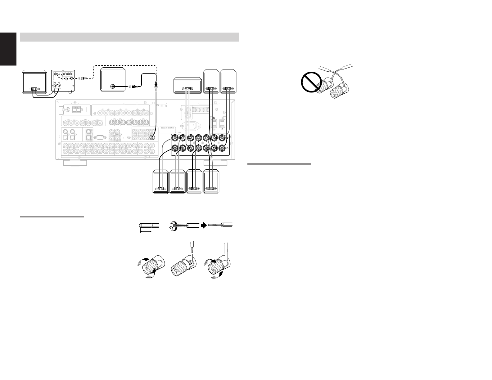
ENGLISH
SPEAKER SYSTEMS : MINIMUM 6 OHMS
FRONT
CENTER
SURROUND
SURROUND BACK
M. SPEAKER B
MULTI
OUT
DVD
C
OUT
S-VIDEO
DVD
DSS/VCR2
C
RS-232C
RC
MULTI
OUT
DSS/VCR2
OUT
OUT
VCR1
VCR1
L
SBR
SBL
OUT
PRE
L
R
DSS/VCR2
DVDTVTV
R
IN
R
SW
RC-5
IN
SR
AUDIO
7.1CH
IN
OUT
IN
SL
SBR
SBL
CD
OUT
SW
OUT
CDR/MD
TAPE
OUTININ
OUT
VIDEO
MONITOR
VCR1
TV
OUT
(
AUX2
)
MONITOR
DIGITAL IN
DIGITAL OUT
3
1
OPT.
2
4
COAX.
L
R
L
SWITCHED
UNSWITCHED
1A 120W MAX
1A 120W MAX
FM
(
Ω
)
ANTENNA
GNDAMAM
COMPONENT VIDEO
C
B
/
P
B
C
R
/
P
R
C
R
/
P
R
C
R
/
P
R
C
B
/
P
B
C
B
/
P
B
INPUT-1
Y
Y
MONITOR OUT
INPUT-2
Y
OUT
AC OUTLETS
120V 60Hz
AC IN
IR EMITTER OUT
R
1
L
4
MULTI FIXED OUT
IN
FLASHER
MODEL NO. ZR6001
SPEAKER SYSTEMS : MINIMUM 6 OHMS
FRONT
CENTER
SURROUND
SURROUND BACK
M. SPEAKER B
L
R
L
OUT
PRE
SW
CONNECTING SPEAKERS
PASSIVE
SUBWOOFER
POWER
AMPLIFIER
INVERT
INPUT
BTL REMOTE CONT.EXT. CONT. IN
INPUT
OUTPUT
LEVEL
MASTERSLAVE
MIN MAX
VIDEO/
SYSTEM OUT OUT
+5~13V DC
S
E
U
F
SPEAKER SYSTEM
MINIMUM 4 OHMS
FM
VIDEO
TVTVDVD
3
1
L
R
Caution:
• Be sure to use speakers with the specified
impedance as shown on the rear panel of this unit.
POWERED
SUBWOOFER
IN
or
CENTER
SURROUND
BACK
RIGHT
LEFT
• To prevent damage to circuitry, do not let the bare
speaker wires
touch each other
and do not let them
touch any metal
part of this unit.
• Do not touch the
speaker terminals
when the power is
on. It may cause
ANTENNA
(
)
7575Ω
GND
DSS/VCR2
VCR1
ININOUT
ININOUT
DIGITAL IN
DIGITAL OUT
4
COAX.
OPT.
2
VCR1
DSS/VCR2
DVD
IN
OUT
OUT
COMPONENT VIDEO
INPUT-1
C
B
C
R
Y
/
/
P
B
P
R
S-VIDEO
MONITOR
RS-232C
DVD
TV
OUT
MULTI
RC-5
RC
CD
TAPE
IN
ININOUT
AUDIO
MONITOR OUT
INPUT-2
C
R
C
R
C
B
C
B
Y
Y
/
/
/
/
P
R
P
R
P
B
P
B
DSS/VCR2
VCR1
ININOUT
IN
OUT
CDR/MD
OUT
MONITOR
OUT
ININOUT
C
SBL
SLSLL
FLASHER
IN
R
SR
MULTI
LLSL
OUT
SRSRR
(
)
AUX2
MODEL NO. ZR6001
PRE
PRE
OUT
OUT
SBR
SW
SW
C
SBL
7.1CH
IN
SBR
SW
AC IN
RRL
RRL
FRONT
FRONT
SPEAKER SYSTEMS : MINIMUM 6 OHMS
SPEAKER SYSTEMS : MINIMUM 6 OHMS
MULTI FIXED OUT
L
R
CENTER
CENTER
IR EMITTER OUT
1
22334
RRL
RRL
SURROUND
SURROUND
AC OUTLETS
120V 60Hz
SWITCHED
1A 120W MAX
SURROUND BACK
SURROUND BACK
M. SPEAKER B
M. SPEAKER B
UNSWITCHED
1A 120W MAX
LLR
LLR
you to receive an electric shocks.
• Do not connect more than one speaker cable to
one speaker terminal. Doing so may damage this
unit.
Note:
• Be sure to connect the positive and negative
cables for the speaker properly. If they are missconnected, the signal phase will be reversed and
the signal quality will be corrupted.
CONNECTING A SUBWOOFER
Use the PRE OUT SUBWOOFER jack to connect
a powered subwoofer (power amplifier built in).
If your subwoofer is a passive type (power
amplifier is not built in), connect a monaural power
amplifier to the PRE OUT SUBWOOFER jack and
RIGHT LEFT
FRONT
RIGHTLEFT
SURROUND
connect the subwoofer to the amplifier.
CONNECTING SPEAKER WIRE
1.
Strip away approx. 3/8 inch (10 mm) of wire
insulation.
2.
Twist the bared wire ends tight, to prevent
short circuits.
3.
Loosen the knob by turning it counterclockwise.
4.
Insert the bare part of the wire into the hole in
side of each terminal.
5.
Tighten the knob by turning it clockwise to
secure the wire.
14
1. 2.
3/8 inch
(10 mm)
3. 4. 5.
Page 18
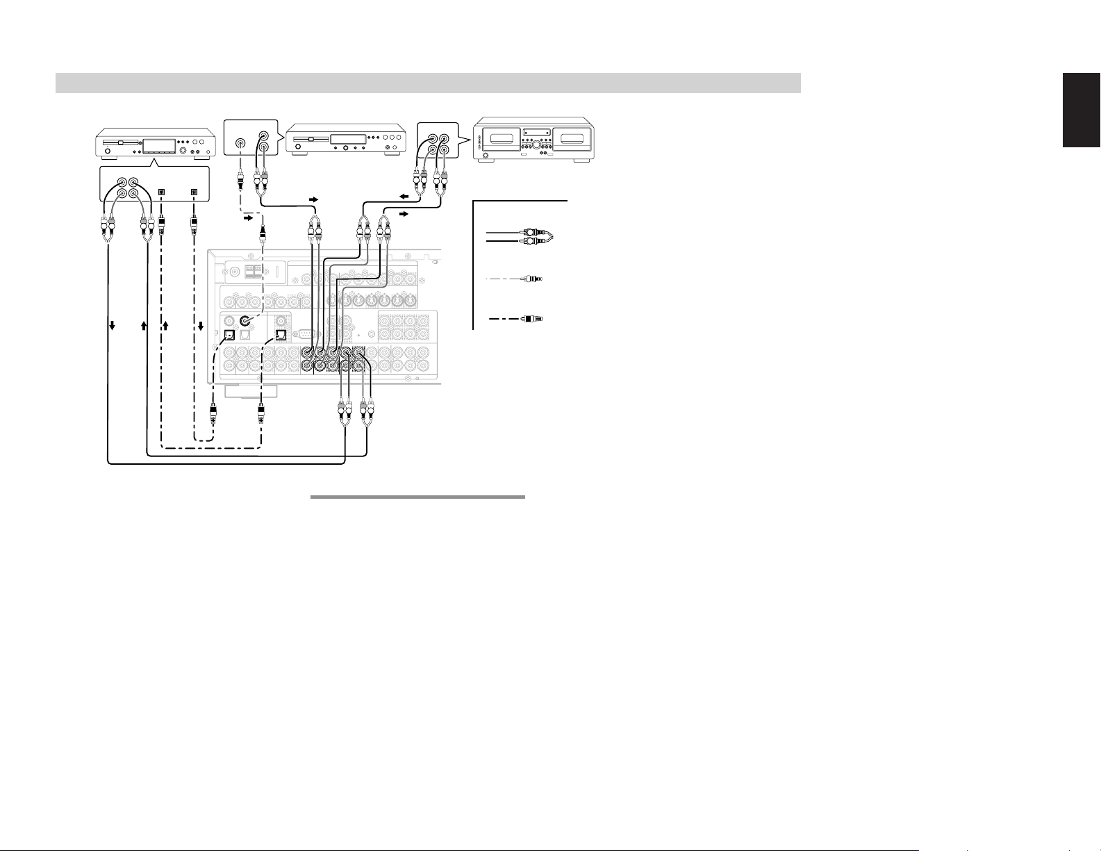
CONNECTING AUDIO COMPONENTS
MULTI
OUT
DVD
C
OUT
S-VIDEO
DVD
DSS/VCR2
C
RS-232C
RC
MULTI
OUT
DSS/VCR2
OUT
OUT
VCR1
VCR1
L
SBR
SBL
OUT
PRE
L
R
DSS/VCR2
DVDTVTV
R
IN
R
SW
RC-5
IN
SR
AUDIO
7.1CH
IN
OUT
IN
SL
SBR
SBL
CD
OUT
SW
OUT
CDR/MD
TAPE
OUTININ
OUT
VIDEO
MONITOR
VCR1
TV
OUT
(
AUX2
)
MONITOR
DIGITAL IN
DIGITAL OUT
3
1
OPT.
2
4
COAX.
FM
(
Ω
)
ANTENNA
GNDAMAM
COMPONENT VIDEO
C
B
/
P
B
C
R
/
P
R
C
R
/
P
R
C
R
/
P
R
C
B
/
P
B
C
B
/
P
B
INPUT-1
Y
Y
MONITOR OUT
INPUT-2
Y
OUT
IN
FLASHER
AUDIO
IN
CD
OUT
OUT
CDR/MD
TAPE
DIGITAL IN
1
OPT.
CD RECORDER / MD DECK
OUT IN
DIGITAL
DIGITAL
INPUT
LRL
OUTPUT
R
R L
RL
The output audio signal from the TAPE OUT jack
and the CD-R/MD OUT jack is the same signal
which is currently selected.
Caution:
• Do not connect this unit and other components to
mains power until all connections between
components have been completed.
Notes:
• Insert all plugs and connectors securely.
Incomplete connections may make noise.
• Be sure to connect the left and right channels
properly.
Red connectors are for the R (right) channel, and
white connectors are for the L (left) channel.
• Be sure to connect input and output properly.
• Refer to the instructions for each component that
is connected to this unit.
• Do not bind audio/video connection cables with
power cords and speaker cables this will result in
generating a hum or other noise.
TAPE DECK
ANALOG AUDIO
L R
DIGITAL AUDIO
(COAXIAL)
DIGITAL AUDIO
(OPTICAL)
ENGLISH
VIDEO
3
1
1
L
R
DIGITAL
OUTPUT
(
FM
7575Ω
TVTVDVD
DIGITAL IN
DIGITAL IN
4
2
DVD
CD PLAYER
OUT IN
LRL
L R
R
L R
L R
OUT
L
R
RL RL RL
ANTENNA
)
GND
DSS/VCR2
VCR1
ININOUT
ININOUT
DIGITAL OUT
COAX.
OPT.
OPT.
VCR1
DSS/VCR2
OUT
OUT
IN
COMPONENT VIDEO
INPUT-1
C
B
C
R
Y
Y
/
/
P
B
P
R
S-VIDEO
MONITOR
RS-232C
DVD
TV
OUT
MULTI
RC-5
RC
CD
TAPE
CD
TAPE
IN
ININOUT
IN
ININOUT
AUDIO
AUDIO
MONITOR OUT
INPUT-2
C
R
C
R
C
B
C
B
Y
/
/
/
/
P
R
P
R
P
B
P
B
DSS/VCR2
VCR1
ININOUT
IN
OUT
CDR/MD
CDR/MD
OUT
OUT
MONITOR
ININOUT
OUT
C
SBL
SLSLL
FLASHER
IN
R
MULTI
LLSL
OUT
(
)
AUX2
PRE
OUT
SBR
SW
SR
C
SBL
7.1CH
IN
SBR
SW
SRSRR
R L R L
CONNECTING DIGITAL AUDIO COMPONENTS
• There are 4 digital inputs, 2 coaxial jacks and 2
optical jacks, on the rear panel. You can use
these jacks to input PCM, Dolby Digital and DTS
bitstream signals from a CD, DVD, or other
digital source components.
• There is one digital output coaxial jack and one
optical output jack on the rear panel. These
jacks can be connected to a CD recorder-, or a
MD deck inputs, respectively.
• Refer to the instructions for each component. To
setup the digital audio format of DVD player, or
other digital source’s connected to digital input
jacks.
Notes:
• There is no Dolby Digital RF input jack. Please
use an external RF demodulator Dolby Digital
decoder when connecting the Dolby Digital RF
output jack of the video disc player to the digital
input jack.
• The digital signal jacks on this unit conform to the
EIA standard. If you use a cable that does not
conform to this standard, this unit may not
function properly.
• Each type of audio jack works independently.
Signals input through the digital and analog jacks
are output through the corresponding digital and
analog jacks, respectively.
• Use fiber optical cables (optical) for DIG-1,2
input jacks. Use 75 ohms coaxial cables (for
digital audio or video) for DIG-3, 4 input jacks.
• You can designate the input for each digital
input/output jacks according to your component.
See page 20.
15
Page 19
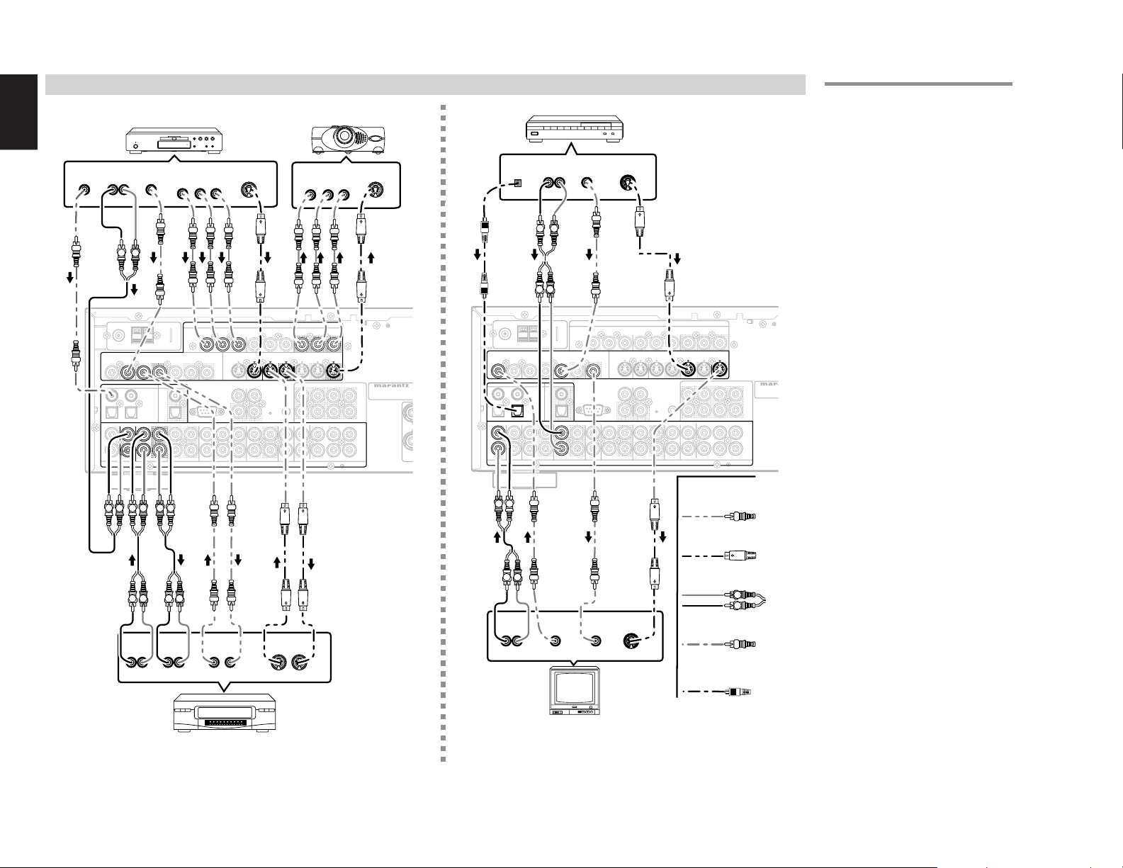
ENGLISH
SPEAKER SYSTEMS : MINIMUM 6 OHMS
MULTI
OUT
DVD
C
OUT
S-VIDEO
DVD
DSS/VCR2
C
RS-232C
RC
MULTI
OUT
DSS/VCR2
OUT
OUT
VCR1
VCR1
L
SBR
SBL
OUT
PRE
L
R
DSS/VCR2
DVDTVTV
R
IN
R
SW
RC-5
IN
SR
AUDIO
7.1CH
IN
OUT
IN
SL
SBR
SBL
CD
OUT
SW
OUT
CDR/MD
TAPE
OUTININ
OUT
VIDEO
MONITOR
VCR1
TV
OUT
(
AUX2
)
MONITOR
DIGITAL IN
DIGITAL OUT
3
1
OPT.
2
4
COAX.
RRL
FM
(
Ω
)
ANTENNA
GNDAMAM
COMPONENT VIDEO
C
B
/
P
B
C
R
/
P
R
C
R
/
P
R
C
R
/
P
R
C
B
/
P
B
C
B
/
P
B
INPUT-1
Y
Y
MONITOR OUT
INPUT-2
Y
OUT
IN
FLASHER
MODEL NO. ZR6001
DVD
DVD
OUT
VCR1
OUT
OUT
MONITOR
DIGITAL IN
3
COMPONENT VIDEO
AUDIO
VIDEO
COMPONENT VIDEO
C
B
/
P
B
C
R
/
P
R
C
R
/
P
R
C
B
/
P
B
INPUT-1
Y
Y
MONITOR OUT
VCR1
DVD
IN
VCR1
AUDIO
MULTI
OUT
DVD
C
OUT
S-VIDEO
DVD
DSS/VCR2
C
RS-232C
RC
MULTI
OUT
DSS/VCR2
OUT
OUT
VCR1
VCR1
L
SBR
SBL
OUT
PRE
L
R
DSS/VCR2
DVDTVTV
R
IN
R
SW
RC-5
IN
SR
AUDIO
7.1CH
IN
OUT
IN
SL
SBR
SBL
CD
OUT
SW
OUT
CDR/MD
TAPE
OUTININ
OUT
VIDEO
MONITOR
VCR1
TV
OUT
(
AUX2
)
MONITOR
DIGITAL IN
DIGITAL OUT
3
1
OPT.
2
4
COAX.
FM
(
Ω
)
ANTENNA
GNDAMAM
COMPONENT VIDEO
C
B
/
P
B
C
R
/
P
R
C
R
/
P
R
C
R
/
P
R
C
B
/
P
B
C
B
/
P
B
INPUT-1
Y
Y
MONITOR OUT
INPUT-2
Y
OUT
IN
FLASHER
TV
IN
DSS/VCR2
DSS/VCR2
OUT
L
DSS/VCR2
TV
R
AUDIO
IN
VIDEO
MONITOR
OUT
MONITOR
DIGITAL IN
2
S-VIDEO
OMODEL NO. ZR6001
CONNECTING VIDEO COMPONENTS
DVD PLAYER
DIGITAL
OUT
AUDIO
OUT
VIDEO
OUT
COMPONENT
VIDEO OUT
YCB/PBCR/P
R
LR
L R
ANTENNA
(
)
FM
7575Ω
GND
VIDEO
VIDEO
VCR1
DVD
VCR1
TVTVDVD
ININOUT
ININOUT
DIGITAL IN
DIGITAL OUT
DIGITAL IN
3
4
2
DVD
DVD
L R L R
AUDIO
OUT
LR
COAX.
OPT.
VCR1
VCR1
IN
OUT
IN
AUDIO
IN
LR
3
1
L
R
L R L R LR
DSS/VCR2
ININOUT
DSS/VCR2
OUT
MONITOR
RS-232C
INPUT-1
INPUT-1
C
C
Y
Y
OUT
CD
AUDIO
AUDIO
AUDIO
VIDEO
OUT IN
S-VIDEO
B
C
B
C
/
/
P
B
P
B
S-VIDEO
RC-5
TAPE
ININOUT
OUT
COMPONENT VIDEO
COMPONENT VIDEO
COMPONENT VIDEO
R
R
Y
/
/
P
R
P
R
DVD
TV
DVD
MULTI
RC
CDR/MD
IN
INPUT-2
C
IN
OUT
OUT
VIDEO PROJECTOR
COMPONENT
VIDEO IN
YCB/PBCR/P
MONITOR OUT
MONITOR OUT
C
R
B
/
P
ININOUT
ININOUT
S-VIDEO
OUT IN
C
C
Y
Y
/
P
R
B
DSS/VCR2
VCR1
VCR1
ININOUT
FLASHER
IN
R
MULTI
LLSL
OUT
(
)
AUX2
C
R
B
C
R
B
/
/
/
/
P
R
P
B
P
R
P
B
MONITOR
MONITOR
OUT
OUT
SBL
SLSLL
SR
SBR
SBL
SRSRR
SBR
S-VIDEO
IN
R
C
MODEL NO. ZR6001
PRE
OUT
SW
C
7.1CH
IN
SW
VIDEO, S-VIDEO , COMPONENT JACKS
SATELLITE TUNER
AUDIO
DIGITAL
OUT
OUT
VIDEO
OUT
S-VIDEO
OUT
LR
L R
L R
MONITOR
MONITOR
RS-232C
COMPONENT VIDEO
INPUT-1
C
B
C
R
Y
OUT
CD
AUDIO
AUDIO
/
P
B
S-VIDEO
S-VIDEO
TAPE
ININOUT
Y
/
P
R
DVD
TV
MULTI
RC-5
RC
CDR/MD
IN
INPUT-2
C
IN
OUT
OUT
B
/
P
B
VCR1
ININOUT
FLASHER
MONITOR OUT
C
R
/
IN
MULTI
OUT
C
R
C
B
Y
/
/
P
R
DSS/VCR2
DSS/VCR2
ININOUT
IN
R
LLSL
(
AUX2
P
R
P
B
MONITOR
MONITOR
OUT
OUT
C
SBL
SLSLL
SR
SRSRR
)
MODEL N
PRE
OUT
SBR
SW
SBL
C
7.1CH
IN
SBR
SW
VIDEO
ANTENNA
(
)
FM
7575Ω
GND
VIDEO
VIDEO
TVTVDVD
TV
DIGITAL IN
DIGITAL IN
3
4
2
1
2
DVD
TV
L
L
R
S
R
VCR1
ININOUT
VCR1
IN
COAX.
OPT.
OUT
DIGITAL OUT
DSS/VCR2
DSS/VCR2
ININOUT
ININOUT
DSS/VCR2
DSS/VCR2
IN
OUT
LR
S-VIDEO
L R
AUDIO
OUT
VIDEO
OUT
VIDEO
IN
S-VIDEO
IN
ANALOG AUDIO
L R
DIGITAL AUDIO
(COAXIAL)
LR
DIGITAL AUDIO
(OPTICAL)
There are 3 types of video jacks on the rear panel.
VIDEO jack
The video signal for the VIDEO jacks is the
conventional composite video signal.
S-VIDEO jack
The video signal is separated into luminance (Y)
and color (C) signals for the S-VIDEO jack. The SVIDEO signals enables high-quality color
reproduction. If your video component has an SVIDEO output, we recommend to use it. Connect
the S-VIDEO output jack on your video component
to the S-VIDEO input jack on this unit.
Component jack
Make component video connections to a TV or
monitor with component inputs to produce higher
quality video images. Use a component video
cable or 3 video cords to connect the component
video out jacks on the ZR6001 to the monitor.
Notes:
•
Be sure to connect the left and right audio channels
properly.
Red connectors are for the R (right) channel, and
white connectors are the for L (left) channel.
• Be sure to connect the inputs and outputs of the
video signals properly.
• If you connect the S-VIDEO or component signal
to the S-VIDEO or component jack on this unit, it
is not necessary to connect the conventional video
signal to the VIDEO (composite) jack. If you use
both video inputs, this unit gives priority to the SVIDEO signal.
• Each type of video jack works independently.
Signals input to the VIDEO (composite) and SVIDEO jacks or component are output to the
corresponding VIDEO (composite) and S-VIDEO
or component jacks, respectively.
• This unit has the “TV-AUTO ON/OFF” function
to turn the TV ON or OFF automatically, by
sensing the incoming video signal from the
VIDEO jacks.
• You may need to setup the digital audio output
format of your DVD player, or other digital source
components. Refer to the instructions of the each
component connected to the digital input jacks.
• There is no Dolby Digital RF input jack. Please
use an external RF demodulator with a Dolby
Digital decoder to connect a video disc player
which has a Dolby Digital RF output jack to the
digital input jack on this unit.
16
TV
VCR
Page 20
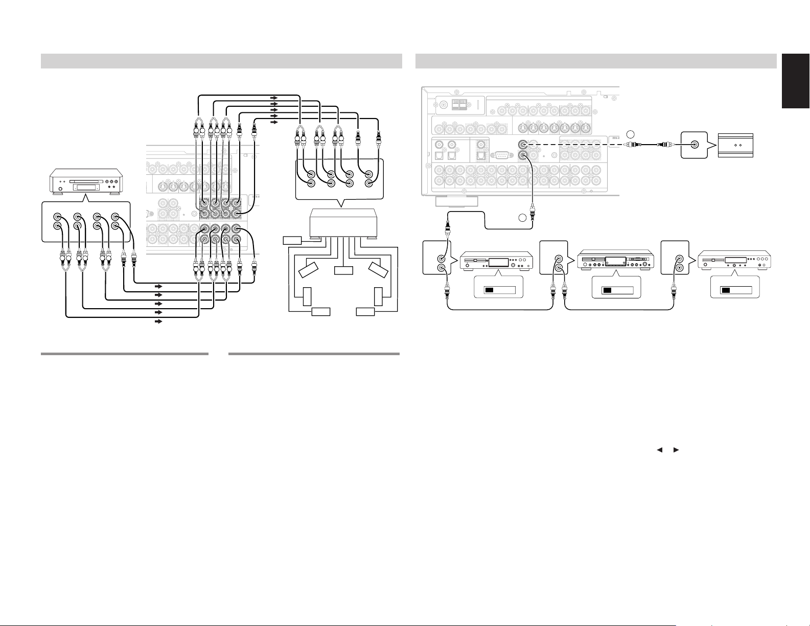
ADVANCED CONNECTING
MULTI
OUT
C
OUT
S-VIDEO
DVD
DSS/VCR2
C
CRS-232C
RC
MULTI
SBR
SBL
OUT
PRE
L
R
R
SW
RC-5
IN
SR
AUDIO
7.1CH
IN
IN
SL
SBR
SBL
OUT
SW
OUT
CDR/MD
TAPE
OUT
RMONITOR
VCR1
TV
OUT
(
AUX2
)
MONITOR
COMPONENT VIDEO
C
B
/
P
B
C
R
/
P
R
C
R
/
P
R
C
R
/
P
R
C
B
/
P
B
C
B
/
P
B
INPUT-1
Y
MONITOR OUT
INPUT-2
Y
OUT
IN
FLASHER
LMODEL NO. ZR6001
C
C
SBR
SBL
OUT
PRE
L
R
R
SW
SR
7.1CH
IN
SL
SBR
SBL
SW
MULTI
OUT
DVD
C
OUT
S-VIDEO
DVD
DSS/VCR2
C
RS-232C
RC
MULTI
OUT
DSS/VCR2
OUT
OUT
VCR1
VCR1
L
SBR
SBL
OUT
PRE
L
R
DSS/VCR2
DVDTVTV
R
IN
R
SW
RC-5
IN
SR
AUDIO
7.1CH
IN
OUT
IN
SL
SBR
SBL
CD
OUT
SW
OUT
CDR/MD
TAPE
OUTININ
OUT
VIDEO
MONITOR
VCR1
TV
OUT
(
AUX2
)
MONITOR
DIGITAL IN
DIGITAL OUT
3
1
OPT.
2
4
COAX.
FM
(
Ω
)
ANTENNA
GNDAMAM
COMPONENT VIDEO
C
B
/
P
B
C
R
/
P
R
C
R
/
P
R
C
R
/
P
R
C
B
/
P
B
C
B
/
P
B
INPUT-1
Y
Y
MONITOR OUT
INPUT-2
Y
OUT
IN
FLASHER
LMODEL NO. ZR6001
RC-5
CONNECTING TO THE RC-5 (MARANTZ PRODUCTS ONLY)
RS-232C
COMPONENT VIDEO
INPUT-1
C
B
C
R
Y
MONITOR
OUT
CD
Y
/
/
P
B
P
R
S-VIDEO
DVD
TV
MULTI
RC-5
RC-5
RC
CDR/MD
TAPE
IN
ININOUT
AUDIO
INPUT-2
C
B
ININOUT
IN
OUT
OUT
MONITOR OUT
C
R
C
R
C
B
Y
/
/
P
P
B
VCR1
FLASHER
IN
MULTI
OUT
/
/
R
P
R
P
B
DSS/VCR2
MONITOR
ININOUT
OUT
2
MODE
PRE
OUT
RC OUT
OPTION
7.1CH
IN
(
AUX2
R
LLSL
C
SBL
SLSLL
SBR
SW
SR
C
SBL
SRSRR
SBR
SW
)
ENGLISH
1
REMOTE
CONTROL
IN
OUT
MD DECK
EXTERNAL INTERNAL
REMOTE
CONTROL
IN
OUT
CD PLAYER
EXTERNAL INTERNAL
w
Whenever external infrared sensors or similar
devices are connected to RC-5 IN of the ZR6001,
be sure to always disable operation of the infrared
sensor on the main unit by using the following
procedure.
1.
Hold down the MULTI button and MENU
button on the front panel at the same time for
five seconds.
2.
The setting “IR=ENABLE” is shown on the FL
DISPLAY.
3.
Press the or cursor button to change this
to “IR=DISABLE”.
4.
Press the ENTER button. Once this setting is
made, the infrared sensor on the main unit is
disabled.
Note:
• Be sure to set to “IR=ENABLE” when external
infrared sensors or similar devices are not
connected. Otherwise, the main unit will be
unable to receive remote control commands.
5.
To restore the original setting, perform steps 1
to 4 to set to “IR=ENABLE”.
17
ANTENNA
(
)
FM
7575Ω
GND
VIDEO
DVD AUDIO PLAYER
SACD MULTI CHANNEL
or
PLAYER
CENTER
L
R
FRONT SURR.
SURR.
BACK
SUB
WOOFER
RL RLRL
INPUT-1
C
AUDIO
B
/
P
B
S-VIDEO
TAPE
ININOUT
COMPONENT VIDEO
C
R
/
P
R
TV
RC-5
TVTVDVD
LR
LR LR
MONITOR OUT
INPUT-2
C
R
C
R
C
/
P
B
VCR1
ININOUT
B
Y
/
P
FLASHER
IN
MULTI
OUT
/
/
R
P
R
P
B
DSS/VCR2
MONITOR
ININOUT
OUT
SBL
SLSLL
C
SBL
SLSLL
C
MODE
PRE
PRE
OUT
OUT
SBR
R
SW
SR
SBR
R
SW
SR
LLSL
LLSL
(
AUX2
C
SBL
C
SBL
7.1CH
7.1CH
IN
IN
SBR
SW
SRSRR
SRSRR
SBR
SW
)
C
B
Y
DVD
MULTI
RC
IN
OUT
CDR/MD
IN
OUT
POWER
AMPLIFER
Subwoofer
R L
R L
L
R
FRONT SURR.
R L
SURR.
BACK
CENTER
SUB
WOOFER
3
1
L
R
REMOTE
CONTROL
DIGITAL IN
4
2
DVD
IN
RL RL RL
Front
Left
Surround
Left
Surround
Back Left
Center
Surround
Front
Right
Right
Surround
Back Right
OUT
DSS/VCR2
VCR1
ININOUT
ININOUT
DIGITAL OUT
COAX.
OPT.
VCR1
DSS/VCR2
IN
OUT
OUT
CD RECORDER
EXTERNAL INTERNAL
q
CONNECTING MULTI CHANNEL AUDIO SOURCE
The 7.1CH INPUT jacks are for multichannel
audio source such as a SACD multichannel
player, DVD audio player or external decoder.
If you use these jacks, switch on the 7.1CH INPUT
CONNECTING AN EXTERNAL POWER AMPLIFIER
The PREOUT jacks are for connecting external
power amplifiers.
Be sure to connect each speaker to the corresponding
external power amplifier.
and set the 7.1CH INPUT level by using the
SETUP MAIN MENU. See page 32.
You can control other Marantz products through
this unit with the remote control by connecting the
REMOTE CONTROL terminals on each unit.
The signal transmitted from the remote control is
received by the remote sensor on this unit. Then
the signal is sent to the connected device through
this terminal. Therefore you need to aim the
remote signal only to the unit. Also, if a Marantz
power amplifier (some models excluded) is
connected to one of these terminals, the power
amplifier’s, power switch is synchronized with this
unit’s power switch.
Set the REMOTE CONTROL SWITCH on the units,
other than the main unit to EXT.(EXTERNAL) for
this feature.
Page 21
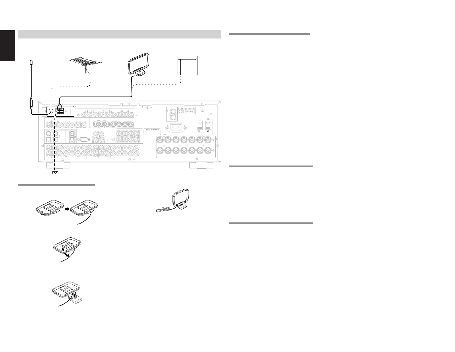
ENGLISH
SPEAKER SYSTEMS : MINIMUM 6 OHMS
FRONT
CENTER
SURROUND
SURROUND BACK
M. SPEAKER B
MULTI
OUT
DVD
C
OUT
S-VIDEO
DVD
DSS/VCR2
C
RS-232C
RC
MULTI
OUT
DSS/VCR2
OUT
OUT
VCR1
VCR1
L
SBR
SBL
OUT
PRE
L
R
DSS/VCR2
DVDTVTV
R
IN
R
SW
RC-5
IN
SR
AUDIO
7.1CH
IN
OUT
IN
SL
SBR
SBL
CD
OUT
SW
OUT
CDR/MD
TAPE
OUTININ
OUT
VIDEO
MONITOR
VCR1
TV
OUT
(
AUX2
)
MONITOR
DIGITAL IN
DIGITAL OUT
3
1
OPT.
2
4
COAX.
L
R
L
SWITCHED
UNSWITCHED
1A 120W MAX
1A 120W MAX
FM
(
Ω
)
ANTENNA
GNDAMAM
COMPONENT VIDEO
C
B
/
P
B
C
R
/
P
R
C
R
/
P
R
C
R
/
P
R
C
B
/
P
B
C
B
/
P
B
INPUT-1
Y
Y
MONITOR OUT
INPUT-2
Y
OUT
AC OUTLETS
120V 60Hz
AC IN
IR EMITTER OUT
R
1
L
4
MULTI FIXED OUT
IN
FLASHER
MODEL NO. ZR6001
FM
(
Ω
)
ANTENNA
GNDAMAM
CONNECTING THE ANTENNA TERMINALS
FM EXTERNAL
VCR1
ININOUT
VCR1
IN
ANTENNA
ANTENNA
COAX.
OUT
DIGITAL OUT
OPT.
ANTENNA
DSS/VCR2
MONITOR
ININOUT
RS-232C
DSS/VCR2
OUT
COMPONENT VIDEO
INPUT-1
C
B
C
R
Y
OUT
CD
AUDIO
/
P
B
S-VIDEO
TAPE
ININOUT
Y
/
P
R
DVD
TV
MULTI
RC-5
RC
CDR/MD
IN
FM ANTENNA
3
1
L
R
VIDEO
FM
FM
TVTVDVD
(
)
(
)
7575Ω
7575Ω
GND
GND
DIGITAL IN
4
2
DVD
ASSEMBLING THE AM LOOP ANTENNA
1.
Release the vinyl tie and take out the
connection line.
INPUT-2
IN
OUT
C
B
/
P
ININOUT
OUT
CONNECTING THE SUPPLIED ANTENNAS
AM LOOP
ANTENNA
MONITOR OUT
C
R
C
R
C
B
Y
/
/
/
P
R
P
R
P
B
VCR1
B
DSS/VCR2
MONITOR
OUT
ININOUT
C
SBL
SLSLL
FLASHER
IN
R
SR
MULTI
LLSL
OUT
SRSRR
(
)
AUX2
MODEL NO. ZR6001
PRE
OUT
SBR
SW
C
SBL
7.1CH
IN
SBR
SW
AM EXTERNAL
MULTI FIXED OUT
L
R
AC IN
RRL
FRONT
CENTER
SPEAKER SYSTEMS : MINIMUM 6 OHMS
ANTENNA
IR EMITTER OUT
1
22334
RRL
SURROUND
AC OUTLETS
120V 60Hz
SWITCHED
1A 120W MAX
SURROUND BACK
M. SPEAKER B
UNSWITCHED
1A 120W MAX
LLR
Connecting the supplied FM antenna
The supplied FM antenna is for indoor use only.
During use, extend the antenna and move it in
various directions until the clearest signal is received.
Fix it with push pins or similar implements in the
position that will cause the least amount of distortion.
If you experience poor reception quality, an
outdoor antenna may improve the quality.
Connecting the supplied AM loop antenna
The supplied AM loop antenna is for indoor use
only.
Set it in the direction and position it to where you
receive the clearest sound. Put it as far away as
possible from the unit, televisions, speaker cables,
and power cords.
If you experience poor reception quality, an
outdoor antenna may improve the quality.
1.
Press and hold down the lever of the AM
antenna terminal.
2.
Insert the bare wire into the antenna terminal.
3.
Release the lever.
CONNECTING AN FM OUTDOOR ANTENNA
Notes:
4.
Place the antenna on stable surface.
• Keep the antenna away from noise sources (neon
signs, busy roads, etc.).
• Do not put the antenna close to power lines. Keep
it well away from power lines, transformers, etc.
• To avoid the risk of lightning and electrical shock,
grounding is necessary.
18
2.
Bend the base part in the reverse direction.
3.
Insert the hook at the bottom of the loop part
into the slot at the base part.
CONNECTING AN AM OUTDOOR ANTENNA
An outdoor antenna will be more effective if it is
stretched horizontally above a window or outside.
Notes:
• Do not remove the AM loop antenna.
• To avoid the risk of lightning and electrical shock,
grounding is necessary.
Page 22
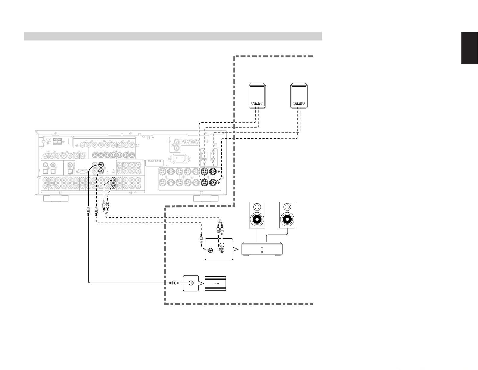
SPEAKER SYSTEMS : MINIMUM 6 OHMS
FRONT
CENTER
SURROUND
SURROUND BACK
M. SPEAKER B
MULTI
OUT
DVD
C
OUT
S-VIDEO
DVD
DSS/VCR2
C
RS-232C
RC
MULTI
OUT
DSS/VCR2
OUT
OUT
VCR1
VCR1
L
SBR
SBL
OUT
PRE
L
R
DSS/VCR2
DVDTVTV
R
IN
R
SW
RC-5
IN
SR
AUDIO
7.1CH
IN
OUT
IN
SL
SBR
SBL
CD
OUT
SW
OUT
CDR/MD
TAPE
OUTININ
OUT
VIDEO
MONITOR
VCR1
TV
OUT
(
AUX2
)
MONITOR
DIGITAL IN
DIGITAL OUT
3
1
OPT.
2
4
COAX.
L
R
L
SWITCHED
UNSWITCHED
1A 120W MAX
1A 120W MAX
FM
(
Ω
)
ANTENNA
GNDAMAM
COMPONENT VIDEO
C
B
/
P
B
C
R
/
P
R
C
R
/
P
R
C
R
/
P
R
C
B
/
P
B
C
B
/
P
B
INPUT-1
Y
Y
MONITOR OUT
INPUT-2
Y
OUT
AC OUTLETS
120V 60Hz
AC IN
IR EMITTER OUT
R
1
L
4
MULTI FIXED OUT
IN
FLASHER
MODEL NO. ZR6001
MULTI
OUT
RC
MULTI
AUDIO
SURROUND BACK
M. SPEAKER B
R
CONNECTING FOR THE MULTI ROOM
(Multi room speaker B)
RIGHT
SPEAKER
LEFT
SPEAKER
ENGLISH
ANTENNA
(
)
FM
7575Ω
GND
VIDEO
TVTVDVD
DIGITAL IN
3
4
1
2
DVD
L
R
DSS/VCR2
VCR1
ININOUT
ININOUT
DIGITAL OUT
COAX.
OPT.
VCR1
DSS/VCR2
IN
OUT
OUT
COMPONENT VIDEO
INPUT-1
C
B
C
R
Y
MONITOR
OUT
RS-232C
CD
Y
/
/
P
B
P
R
S-VIDEO
DVD
TV
MULTI
MULTI
RC-5
RC
RC
CDR/MD
TAPE
IN
ININOUT
AUDIO
AUDIO
L R
INPUT-2
IN
OUT
C
B
/
ININOUT
OUT
P
B
VCR1
FLASHER
C
R
/
P
R
IN
MULTI
MULTI
OUT
OUT
(
AUX2
MONITOR OUT
C
R
C
B
Y
/
/
P
B
DSS/VCR2
MONITOR
ININOUT
OUT
SBL
SLSLL
SBR
R
SR
LLSL
SBL
SRSRR
SBR
)
P
R
C
MODEL NO. ZR6001
PRE
OUT
SW
C
7.1CH
IN
SW
AC IN
RRL
FRONT
SPEAKER SYSTEMS : MINIMUM 6 OHMS
MULTI FIXED OUT
L
R
CENTER
IR EMITTER OUT
1
RRL
SURROUND
22334
AC OUTLETS
120V 60Hz
SWITCHED
1A 120W MAX
SURROUND BACK
SURROUND BACK
M. SPEAKER B
M. SPEAKER B
UNSWITCHED
1A 120W MAX
LLR
LLR
MULTIROOM
MULTIROOM
LEFT
SPEAKER
MULTIROOM
RIGHT
SPEAKER
R L
L
R
FRONTRC IN
MAIN AMP
(For MULTIROOM)
IR RECEIVER
Note:
RC OUT
• You can use surround back speaker terminals as
multi room speaker terminals when you use no
surround back speaker.
19
Page 23

ENGLISH
SETUP
After all components are connected, initial setup
must be performed.
ON SCREEN DISPLAY MENU
SYSTEM
The ZR6001 incorporates an on-screen menu
system, which makes various operations possible
by using the cursor (
buttons on the remote control or on the front panel.
Note:
•
To view the on-screen displays, make certain you
have made a connection from the Monitor Out jack
on the rear panel to the composite, S-Video,
component video input of your TV or projector.
(see page 16)
1.
Press the AMP button of the remote control.
(This step is not needed when operating the
setup menus from the receiver itself.)
2.
Press the MENU button on the remote control
or set to display the “SETUP MAIN MENU” of
the OSD menu system.
There are 8 items in the SETUP MAIN MENU.
3.
Select a desired sub-menu with the
cursor buttons, and press the ENTER button
to enter. The display will change to the
selected sub-menu. You can lock the
condition of setup to each sub-menu with the
or
or cursor buttons.
Note:
• If you desire to adjust any sub-menu, you need to
set it to UNLOCKED.
4.
If you desire to exit from this menu system,
press the EXIT button, or move the cursor to
EXIT and press the ENTER button.
, , , ) and ENTER
or
1INPUTSETUP
CD : D4 - AT TV :
TAPE : ANA DVD :D3- AT
CD - R : D1 -A T VCR1 : ANA
MA I N EX I T
3 PRE FERENCE
STANDBY MODE : ECONOMY
TV-AUTO : ✽✽✽
OSD I NFO : ENABLE
VIDEO CONVERT : ENABLE
MA I N EX I T
4SURROUND
SURR . MODE : AUTO
HT -EQ : OFF
LFE LEVEL :
MA I N E X I T
ANA
DSS : D2 -AT
COMP 1 : DVD
COMP 2 : DSS
✽✽✽
SETUUPMMAIN MENU
1.INPUT SETUP :UNLOCK
2.SPEAKER SETUP:UNLOCK
3 . PREF ERENCE : UNLOCK
4.SURROUND ::UNLOCK
5.PL ICII UNLOCK
6.CSSII :UNLOCK
8.MULTI ROOM :UNLOCK
9 MULT I PL C.
2-1 SPEAKERS SIZE
SUBWOOFER : YES
FRONT L /R : LARGE
CENTER : SMAL L
SURROUND L / R : SMAL L
SURR . BACK : 2CH
SURR . BACK S I ZE : SMAL L
LPF/HPF : 100 HZ
BASS M I X : BOTH
MA I N NE XT E X I T
2 - 2 S PEAKERS D I ST ANCE
FRONT L : 10 f t 3 . 0 m
FRONT R : 10 f t 3 . 0 m
CENTER : 1 0 f t 3 . 0 m
SURR . L : 1 0 f t 3 . 0 m
SURR . R : 1 0 f t 3 . 0 m
SUB W : 10 f t 3 . 0 m
SURR . B L : 1 0 f t 3 . 0 m
SURR . B R : 1 0 f t 3 . 0 m
MA I N R E TU RN N EX T E X I T
2 - 3 SPEAKERS LEVEL
T EST MODE : MANUAL
FRONT L : 0 dB
CENTER : 0 dB
FRONT R : 0 dB
SURR . R : 0 dB
SURR . B R : 0 d B
SURR . B L : 0 d B
SURR . L : 0 dB
SUB W : 0 dB
MA I N R E TU RN EX I T
:UNLOCK77..1CHINPUT
:UNLOCK
EX I T
77.1CHINPUTLEVEL
VIDEO IN : LAST
FRONT L : 0 dB
CENTER : 0 dB
FRONT R : 0 dB
SURR . R : 0 dB
SURR . B R : 0 d B
SURR . B L : 0 d B
SURR . L : 0 dB
SUB W : 0 dB
MA I N E X I T
8MULTI ROOM
VIDEO : DVD
SLEEP T IMER : OFF
MUL T I : OF F MS PK B :
VOL : VAR I VOL :
L EVEL : - 9 0dB LEVEL :
- ---MAIN-ROOM STATUS---V I DEO : DVD AUD I O: DVD
MA I N E X I T
9MULTI PLC
MUL T I
PLC SERVER :ON
CONNE CT I ON MODE :
AUTO
H I GH A UD I O QU AL I TY
HIGH RELIABI LITY
GP
ID SETT ING:START
MA I N EX I T
✽✽✽
✽✽✽
✽✽✽
20
5PL II MUS I C PARAMETER
PARAMETER : DE FAULT
PANORAMA : OF F
DIMENSION : 3
CENTER WI DT H : 3
MA I N E X I T
6CSII PARAMETER
TRUBASS : 0
SRS D I ALOG : 0
MA I N E X I T
Page 24

1 INPUT SETUP (ASSIGNABLE DIGITAL
INPUT AND COMPONENT VIDEO INPUT)
4 digital inputs and 2 component video inputs can
be assigned to a desired source.
Use this menu to select the digital input jack to be
assigned to the input source.
1.
Select “INPUT SETUP” in SETUP MAIN
MENU with
the ENTER button.
CD : D 4 - AT TV : ANA
TAPE :ANA DVD :D3 -AT
CD-R :D1-AT VCR1 :ANA
MA I N EX I T
2.
To select the input source, press the or
cursor buttons.
3.
To select the digital input jack, press the or
cursor buttons.
Select “Dx-AT” for input sources, for automatic
detection of the digital input signal condition.
If there is not a digital signal present, but there
is an analog signal present, the analog signal
will be played.
Select “Dig x”, when only a digital signal will be
used.
no digital input jacks are used.
4.
To select the vdieo source, select “COMP1” or
“COMP2” by pressing the
buttons, and press the
to select the vdieo source to be assigned .
5.
After you complete this portion of the set up,
move the cursor to MAIN with the
cursor buttons and press the ENTER button.
Notes:
• The TUNER, AUX1 and AUX2 are fixed to the
analog input, and cannot be selected for any
digital input.
• When a DTS-LD or DTS-CD is playing, this setup
is not available. This is to avoid noise being
generated from the analog input.
• If “Dx-AT” is selected and a DVD, compact disc
or LD is fast-forwarded during playback, decoded
signals may produce a skipping sound. In such
cases, change the setting to DIGITAL.
or cursor button, and press
1INPUTSETUP
DSS : D2 - AT
COMP 1 : DVD
COMP 2 : DSS
Select “ANA” for input sources for which
or cursor
or cursor buttons
or
2 SPEAKER SETUP
After you have installed the ZR6001, connected all
the components, and determined the speaker
layout, it is now time to perform the settings in the
Speaker Setup menu for the optimum sound
acoustics for your environment and speaker
layout.
Before you perform the following settings, it is
important that you first determine the following
characteristics:
2-1 SPEAKERS SIZE
When setting the speaker size in the SPEAKER
SIZE sub-menu, use the guidelines given below.
LARGE:
The complete frequency range for the channel
you are setting will be output from the speaker.
SMALL:
Frequencies of the channel you are setting
lower than approx. 100 Hz will be output from
the subwoofer.
If the Subwoofer is set to “NONE” and the front
speakers are set to “LARGE,” then the sound
will be output from both the left and right
speakers.
2-1 SPEAKERS SIZE
SUBWOOFER : YES
FRONT L /R : LARGE
CENTER : SMAL L
SURROUND L / R : SMAL L
SURR . BACK : 2CH
SURR . BACK S I ZE : SMAL L
LPF/HPF : 100 HZ
BASS M I X : BOTH
MA I N NE XT E X I T
1.
Select “SPEAKER SETUP” in SETUP MAIN MENU with the ENTER button.
2.
To select the each speaker, press the or
cursor buttons.
3.
To select the setting of each speaker size,
press the
4.
After you complete this portion of the set up,
move the cursor to “NEXT” with the
cursor buttons and then press the ENTER
button to go to the next page.
SUBWOOFER:
YES:
Select when a subwoofer is connected.
NONE:
Select when a subwoofer is not connected.
or cursor button, and press
or cursor buttons.
or
FRONT L/R
LARGE:
Select if the front speakers are large.
SMALL:
Select if the front speakers are small.
• If “NONE” is selected for the Subwoofer setting,
then this setting is fixed to “LARGE.”
CENTER
NONE:
Select if no center speaker is connected.
LARGE:
Select if the center speaker is large.
SMALL:
Select if the center speaker is small.
SURROUND L/R
NONE:
Select if no surround left and right speakers are
connected.
LARGE:
Select if the surround left and right speakers are
large.
SMALL:
Select if the surround left and right speakers are
small.
SURR. BACK
NONE:
Select if no surround back left and right
speakers are connected.
2CH:
Select if the surround back left and right
speakers are connected.
1CH:
Select if the one surround back speaker is
connected.
In this case, the audio signal is emitted form the
Surround L output terminal.
Notes:
• If “NONE” is selected for the Surround L/R
setting, then this setting is fixed to “NONE.”
• You can use surround back speaker terminals as
multi room speaker terminals when you use no
surround back speaker. (See page 19)
SURR. BACK SIZE
LARGE:
Select if the surround back speaker is large.
SMALL:
Select if the surround back speaker is small.
Note:
• If “NONE” is selected for the Surround L/R
setting, then this setting is not available.
LPF/HPF
When you use a subwoofer, you can select the
cutoff frequency for the small speakers used.
Select one of the crossover frequency levels
according to the size of the small speaker
connected.
80Hz:
Select this when the bass speaker is about 12
cm (4 3/4 inches).
100Hz:
Select this when the bass speaker is about 10
cm (3 15/16 inches).
120Hz:
Select this when the bass speaker is about 8 cm
(3 3/16 inches).
Notes:
• Use the above comments as reference when
adjusting.
• If Pure-Direct mode, 7.1CH Input is in use, this
function does not take effect.
BASS MIX
• The bass mix setting is only valid when
“LARGE” is set for the front speakers and “YES”
is set for the subwoofer during stereo playback .
This setting has effect only during playback of
PCM or analog stereo sources.
• When “BOTH” is selected, the low frequencies
will be played through the main L&R, as well as
the sub woofer.
In this playback mode, the low frequency range
expand more uniformly through the room, but
depending on the size and shape of the room,
interference may result in a decrease of the
actual volume of the low frequency range.
• By selecting “MIX”, the low frequencies will play
through the main L&R ONLY.
Note:
• LFE signals during playback of Dolby Digital or
DTS, will be played through the sub woofer.
ENGLISH
21
Page 25

ENGLISH
3 PRE FERENCE
S TANDBY MODE : E CONOMY
TV-AUTO : ✽✽✽
OSD I N FO : ENABL E
V I DEO CONV ERT : ENAB LE
MA I N E X I T
2-2 SPEAKERS DISTANCE
Use this parameter to specify the distance of each
speaker’s position from the listening position. The
delay time is automatically calculated according to
these distances.
Begin by determining the ideal or most commonly
used seating position in the room.
This is important for the timing of the acoustics to
create the proper sound space that the ZR6001
and today’s sound systems are able to produce.
Note:
• For speakers that you have selected “NONE” the
Speaker Configuration sub-menu will not appear
here. (There are several useful books and special
DVD and LD’s available to guide you through
proper home theater configuration. If you are
unsure, have your Marantz dealer perform the
installation for you. They are trained
professionals familiar with even the most
sophisticated custom installations. Marantz
recommends the WWW.CEDIA.ORG website for
further information about this).
2 - 2 S PEAKE RS D I STANCE
FRONT L : 10 f t 3 . 0 m
FRONT R : 10 f t 3 . 0 m
CENTER : 1 0 f t 3 . 0 m
SURR . L : 1 0 f t 3 . 0 m
SURR . R : 1 0 f t 3 . 0 m
SUB W : 10 f t 3 . 0 m
SURR . B L : 10 f t 3 . 0 m
SURR . B R : 10 f t 3 . 0 m
MAI N RETURN NEX T EX I T
1.
To select each speaker , press the or
cursor buttons.
2.
To set the distance for each speaker , press
or cursor buttons.
the
3.
After you complete this portion of the set up,
move the cursor to “NEXT” with the
cursor buttons and then press the ENTER
button to go to the next page.
FRONT L:
Set the distance from the front left speaker to
your normal listening position.
Center:
Set the distance from the center speaker to your
normal listening position.
FRONT R:
Set the distance from the front right speaker to
your normal listening position.
SURR. L:
Set the distance from the surround left speaker
to your normal listening position.
SURR. R:
Set the distance from the surround right speaker
to your normal listening position.
22
or
SUB W:
Set the distance from the subwoofer to your
normal listening position.
SURR. B L:
Set the distance from the surround back left
speaker to your normal listening position.
SURR. B R:
Set the distance from the surround back right
speaker to your normal listening position.
Using the
level of the noise from the speaker so that it is the
same level for all the speakers.
If you select “MANUAL”, adjust the output level of
each speaker as listed below.
1.
Notes:
• Set the distance to each speaker in meters (m) or
feet (ft) as follows.
m: 0.3 - 9 m in 0.3 m steps
ft: 1 - 30 ft in 1 ft steps
• For the speakers that you have selected “NONE”
the Speaker Size menu will not appear.
• The setting for Surr.Back L and Surr.Back R
appears if you set for it to, two surround back
speakers in the Speaker Size menu.
• The setting of Surr.Back appears if it is set for one
surround back speaker in the Speaker Size menu.
2-3 SPEAKERS LEVEL SETTING WITH TEST TONE
Here you will set the volume for each speaker so
that they are all heard by the listener at the same
level. We recommend using a SPL (Sound
Pressure Level) meter, when available.
2.
3.
4.
Note:
• The speaker level settings are not available in 7.1
Channel Input mode, CS mode and Multi Channel
Stereo mode.
2-3 SPEAKERS LEVEL
T ES T MODE : MANUAL
FRONT L : 0 dB
CENTER : 0 dB
FRONT R : 0 dB
SURR . R : 0 dB
SURR . B R : 0 dB
SURR . B L : 0 dB
SURR . L : 0 dB
SUB W : 0 dB
MA I N R ETURN E X I T
TEST MODE :
Selects “MANUAL” or “AUTO” for generating
the mode of the test tone with the
buttons.
If you select “AUTO” , the test tone will be cycled
through in a circular pattern which is Left →Center
→ Right → Surround Right → Surround Back Right
→ Surround Back Left → Surround Left →
Subwoofer → Left →.. increments of 2 seconds
for each channel.
or cursor
After you complete this portion of the set up, press
the ENTER button, the cursor will move to “MAIN”
and then press the ENTER button to go to SETUP
MAIN MENU.
Notes:
• Speakers that you selected “NONE” for in the
• The setting of Surr.Back L and Surr.Back R
•
• To adjust the speaker levels for 7.1-channel input
or cursor buttons, adjust the volume
When you move the cursor to FRONT L by
pressing the
emit a pink noise from the front left speaker.
Remember the level of this noise and then
press the
(Note that this can be adjusted to any level
between -10 and +10 dB in 1 dB intervals
except the subwoofer setting. The subwoofer
can be adjusted to any level between -15 and
+10 dB in 1 dB intervals.)
The ZR6001 will now emit the pink noise from
the center speaker.
Using the and cursor buttons, adjust the
volume level of the noise from the center
speaker so that it is the same level as the front
left speaker.
Press the cursor button again. The ZR6001
will now emit the pink noise from the front right
speaker.
Repeat steps 2 and 3 above for the front right
and other speakers until all speakers are
adjusted to the same volume level.
Speaker Size menu will not appear.
appears if you have set it for two surround back
speakers in the Speaker Size menu.
The setting of Surr.Back appears if you have set it for
one surround back speaker in the Speaker Size menu.
sources, you will need to use the 7.1CH-INPUT
sub menu. (See page 24).
cursor button, the ZR6001 will
cursor button.
3 PREFERENCE
1.
Select “PREFERENCE” in the SETUP MAIN
MENU with the
press the ENTER button.
2.
To select a desired content, press the or
cursor buttons.
STANDBY MODE:
When this function is set to “ECONOMY”, you
can reduce the power consumption when the
unit is in the standby mode.
Note:
• TV-AUTO and RS-232C are disabled in the
“ECONOMY” setting.
TV AUTO:
Select the TV AUTO ON/OFF function to enable
or disable with the
to page 31)
OSD Info:
Select the OSD information function to enable or
disable with the
If you select “ENABLE”, the ZR6001 will display
the status of the feature (Volume up/down, input
select, etc..) on the TV monitor. But if you do not
desire this information, select “DISABLE ”.
VIDEO CONVERT:
Select the VIDEO CONVERT function to enable
or disable with the
cable connection: Refer to page 27)
After you complete this portion of the set up, move
the cursor to “MAIN” with the
and press the
ENTER
or cursor buttons, and
or cursor buttons. (refer
or cursor buttons.
or cursor buttons. (Video
or cursor buttons
button.
Page 26

4 SURROUND
7MULTI ROOM
AUD IO : DVD
SLEEP T IMER : OFF
MU L T I : OF F MS PK B :
✽✽✽
VOL : VAR I VOL : ✽✽✽
L EVEL : - 9 0dB LEVE L : ✽✽✽
- ---MAIN-ROOM STATUS---V I DEO: DVD AUD I O :DVD
MA I N E X I T
4 S URROUND
SURR .MODE : AUTO
HT -EQ : OFF
LFE LEVEL : 0 dB
5 PL II (PRO LOGIC II)
MUSIC PARAMETER
Pro Logic II-Music mode creates a rich and
enveloping surround ambience from stereo
sources such as CDs.
In this mode, ZR6001 includes three controls to
fine-tune the soundfield as follows.
5PL II MUS I C P ARAME T ER
6 CS II (CIRCLE SURROUND II )
PARAMETER
6CSII PARAMETER
TRUBASS : 0
SRS D IALOG : 0
7 MULTI ROOM
ZR6001 has features in MULTI ROOM SYSTEM
such as source selector, sleep timer, Multi Room
Speaker output and remote control.
You can set these feature in this sub-menu.
ENGLISH
MA I N E X I T
1.
Select “SURROUND” in the SETUP MAIN MENU with the press the ENTER button.
2.
To select a desired content , press the or
cursor buttons.
SURR.MODE:
Select the desired surround mode with the
cursor buttons.
HT-EQ:
Select to active the HT-EQ with the or cursor
buttons.
The tonal balance of a film soundtrack will be
excessively bright and harsh when played back
over audio equipment in the home. This is
because film soundtracks were designed to be
played back in large movie theater environments.
Activating the HT-EQ feature when watching a
film made for movie theaters corrects this and
restores the correct tonal balance.
The HT-EQ feature is available except in the
following modes.
• 7.1 CH INPUT
• PURE-DIRECT
• When VIRTUAL is set for the surround mode
LFE LEVEL:
Select the output level of the LFE signal included
in the Dolby Digital signal or the DTS signal.
Select 0 dB, -10 dB or OFF with the or
cursor buttons.
After you complete this portion of the set up, move
the cursor to “MAIN” with the
and press the ENTER button.
or cursor buttons, and
or
or cursor buttons
PARAMET ER : DEFAULT
PANORAMA : OFF
DIMENSION : 3
CENTER W I DTH : 3
MA I N E X I T
Select “PL II MUSIC” in the SETUP MAIN MENU
with the
ENTER button.
PARAMETER:
PANORAMA:
DIMENSION:
CENTER WIDTH:
After you complete this portion of the set up, move
cursor to “MAIN” with the
press the ENTER button.
or cursor buttons, and press the
Select “DEFAULT” or “CUSTOM” with the
cursor buttons.
If you select “CUSTOM”, you can adjust three
parameters as listed below.
Select the Panorama mode On or Off with the
or cursor buttons.
Panorama wraps the sound of the front left and right
speakers around you, for an exciting perspective.
Set the Dimension level between 0 and 6 level in
1 level intervals with the
Adjust the soundfield either towards the front or
towards the rear.
This can be useful to help achieve a more
suitable balance from all the speakers with
certain recordings.
Set the Center width level between 0 and 7 in 1
level intervals with the
Center Width allows you to gradually spread the
center channel sound into the front left and right
speakers.
At its widest setting, all the sound from the
center is mixed into the left and right.
This control may help achieve a more spacious
sound or a better blend for the front image.
If “NONE” was selected for the Center speaker
setting, in the Speaker size set up menu, then
this setting will not appear.
or cursor buttons.
or cursor buttons.
or cursor buttons and
or
MA I N E X I T
1.
Select “CS II ” in the SETUP MAIN MENU with
the
or cursor buttons, and press the
ENTER button.
2.
To Select desired contents as below, press
the
TRUBASS:
SRS DIALOG:
After you complete this portion of the set up, move
cursor to “MAIN” with the
press the
or cursor buttons.
Set the TRUBASS level between 0 and 6 level in
1 level interval with the
TRUBASS produced by the speakers are an
octave below the actual physical capabilities of the
speakers adding exciting, deeper bass effects.
Set the SRS DIALOG level between 0 and 6 in 1
level intervals with the
This can be popped out of the surround audio
effects, allowing the listener to easily discern what
the actors say.
If “NONE” was selected for the Center speaker
setting, in the Speaker size set up menu, then this
setting will not appear.
ENTER
button.
or cursor buttons.
or cursor buttons.
or cursor buttons and
1.
Select “MULTI ROOM” in the SETUP MAIN
MENU with
the ENTER button.
2.
To Select desired contents, press or
cursor button
AUDIO:
Select the audio source of the Multi-room output
with
or cursor buttons.
SLEEP TIMER:
SLEEP timer function is available during the
multiroom is active, set the time with
cursor buttons.
MULTI (MULTI ROOM):
To switch on the Multi-room output ON or OFF,
press
VOL (VOLUME SETUP):
LEVEL (VOLUME LEVEL):
MSPK B (MULTI SPEAKER B):
or cursor button.
Select whether the Multi-room output level is
variable or fixed with a
Adjust the Multi-room output level with
cursor buttons.
To switch on the Multi-speaker B output ON or
OFF, press
or cursor button, and press
or cursor buttons.
or cursor buttons.
Note:
• This setting can be changed when the Surr Back is
set “NONE” in 2-1 SPEAKER SIZE menu.
When this setting is unavailable, “✽✽✽” is
displayed
VOL (VOLUME SETUP):
Select whether the Multi-speaker output level is
variable or fixed with a
or cursor buttons.
Note:
• This setting can be changed when the Surr Back is
set “NONE” in 2-1 SPEAKER SIZE menu.
When this setting is unavailable, “✽✽✽” is
displayed
or
or
23
Page 27

ENGLISH
9MULTI PLC
MULT I
CONNE CT I ON MODE :
AUTO
H I GH AUD I O QUAL I TY
HIGH RELIABILITY
GP
ID SETTING:START
MA I N EX I T
PLC SERVER :ON
1. 3. 2.
LEVEL (VOLUME LEVEL):
Adjust the Multi-speaker output level with
cursor button.
Note:
• This setting can be changed when the Surr Back is
set “NONE” in 2-1 SPEAKER SIZE menu.
When this setting is unavailable, “✽✽✽” is
displayed
MAIN ROOM STATUS:
Selected input source in the main room will be
displayed.
Note:
• If “VOLUME” is set to “FIXED”, the multi-room
output level cannot be adjusted from the second
zone.
After you complete this portion of the set up, move
the cursor to “MAIN” with
press ENTER button.
or cursor buttons and
or
8 7.1 CH INPUT LEVEL
This sub-menu is to adjust the speaker levels for
7.1-channel input sources.
Here you will adjust the volume for each channel so
that they are all heard by the listener at the same
level.
87.1CH INPUTLEVEL
VIDEO IN : LAST
FRONT L : 0 dB
CENTER : 0 dB
FRONT R : 0 dB
SURR . R : 0 dB
SURR . B R : 0 dB
SURR . B L : 0 dB
SURR . L : 0 dB
SUB W : 0 dB
MA I N E X I T
1.
Select “7.1CH INPUT” in the SETUP MAIN
MENU with the
press the ENTER button.
2.
To select “VIDEO IN”, press or cursor
button.
3.
Using the or cursor buttons, select the
video input source which is emitted from
Monitor out in the 7.1 CH INPUT function.
The input source is switched by pressing the
or cursor buttons as follows;
LAST ↔ TV ↔ DVD ↔ VCR1 ↔ DSS ↔
AUX1 ↔ V-OFF ↔ LAST ↔
Notes:
•
When select LAST, the source is set previous
source before 7.1 CH INPUT function
When select V-OFF, no signal is emitted from
•
monitor out terminal.
4.
To Select desired channel , press the or
cursor buttons.
5.
Using the or cursor buttons, adjust the
volume level of each channel.
6.
After you complete this portion of the set up,
move the cursor to “MAIN” with the
cursor buttons and press the ENTER button.
Notes:
•
These settings will be memorized to 7.1CH INPUT
source.
• This feature can be directly selected with the
CH.SEL button of the remote controller.
or cursor buttons, and
is activated.
or
9 MULTI PLC SETUP
This submenu is for setting up the Multi PLC
feature of the ZR6001.
9MULTI PLC
MULT I
CONNE CT I ON MODE :
GP
MA I N EX I T
1.
Select “9. MULTI PLC” in the SETUP MAIN
MENU with the
press the ENTER button.
2.
To select desired contents, press or
cursor button.
MULTI PLC SEVER:
Select “ON” or “OFF” with the / cursor buttons
to turn the Multi PLC Server feature ON/OFF.
CONNECTION MODE:
Select the Connection Mode of the Multi PLC
feature with the
The available Connection Modes are:
- AUTO :Normal mode
Use this mode as standard.
- HIGH AUDIO QUALITY(H-AQ)
Use this mode to listen to high audio quality.
(However, when multiple ZC4001 units are
connected, audio may be lost or noise may
occur in a ZC4001 that experience poor
reception.)
- HIGH RELIABILITY(H-R)
Use this mode when multiple ZC4001 units are
connected, audio is lost, or noise occurs.
PLC SERVER :ON
AUTO
H I GH AUD I O QUAL I TY
HIGH RELIABILITY
ID SETTING:START
or cursor buttons and
/ cursor buttons.
:Emphasizes audio quality.
:Emphasizes reliability.
GP-ID SETTING
To set a Group ID, connect the AC power cables of
the ZR6001 and ZC4001 to wall power outlets as
close to each other as possible.
Set the Group ID simultaneously for the ZR6001
and ZC4001.
<ZR6001>
Using the OSD menu system, set “GP-ID
SETTING” to “START”.
ZR6001ONSCREENDISPLAYMENUSYSTEMZR6001ONSCREENDISPLAYMENUSYSTEM
ZR6001ONSCREENDISPLAYMENUSYSTEM
ZR6001ONSCREENDISPLAYMENUSYSTEMZR6001ONSCREENDISPLAYMENUSYSTEM
1.
Select “9. MULTI PLC” in the SETUP MAIN
MENU with the
press the ENTER button.
2.
Select “GP-ID SETTING” with the or
cursor buttons.
<ZC4001>
1.
Press and hold the ENTER button for 5 sec or
more.
or cursor buttons, and
24
Page 28

2.
Press the button once.
3.
Simultaneously press the ENTER buttons of
the ZR6001 and ZC4001.
<ZC4001>
<ZR6001>
GP-ID SETTING : **
The below message appears when the Group ID
has been successfully set.
<ZC4001>
<ZR6001>
GP-ID SETTING : SUCCEED
The below message appears if the units fail to set
the Group ID.
<ZC4001>
<ZR6001>
GP-ID SETTING : MISSING
Notes:
One possible reason the Group ID cannot be set is
power line noise. In that case, unplug the power
cable of the device that is generating noise, then
plug it back in and try setting the Group ID again.
PLC IR EMITTER OUT SETUP
When the ZR6001 and ZC4001 are connected
over the PLC, the ZC4001 can control output from
other brands.
The ZR6001’s IR EMITTER OUT terminals output
remote control signals from the ZC4001 to an
emitter, which are then picked up by the IR sensor
of other brand products. To control other brand
sources, an IR code must be set. If the IR code of
the source is unknown, the IR code learning
feature must be used.
IR CODE SETTING
1.
Press and hold the MENU button for 5 sec. or
more.
2.
“SET REMOTE IR” appears, followed by
“INPUT IR CODE”.
3.
Press the ENTER button.
4.
Select a function to be controlled by ZR6001
with the
(Select from DVD, TV, VCR1, DSS, AUX1,
TAPE, CD-R and CD.)
“FUNCTION : DVD”
5.
Press the ENTER button.
6.
Select a source device of the other brand with
the
CODES table at the end of this guide.
Select from TV, CABLE, V.ACC, DSS, VCR,
LD, DVD, TUNER, AMP, CD, HOME, TAPE,
CD-R and AUX.)
“DEVICE : DVD”
7.
Press the ENTER button.
8.
Input the code of the source with the /
buttons. Move to other digits in the code with
the
“CODE NR : 6000”
9.
After inputting the code, press the ENTER
button.
“WRONG NUMBER” appears if an incorrect
code is input. In that case, press the ENTER
button.
“CHECK IR CODE” appears followed by
“CODE: POWER” if the correct code is input.
10.
Press the ENTER button to output the Power
Code from the IR EMITTER OUT terminal and
subsequently via the emitter as a test.
/ buttons.
/ buttons. (See the PLC REMOTE
/ buttons.
IR CODE LEARNING
1.
Press and hold the MENU button for 5 sec. or
more.
2.
“SET REMOTE IR” appears, followed by
“INPUT IR CODE”.
3.
Select “LEARN IR CODE” with the /
buttons.
4.
Press the ENTER button.
5.
Select a function to be controlled by ZR6001
with the
(Select from DVD, TV, VCR1, DSS, AUX1,
TAPE, CD-R and CD.)
“FUNCTION : DVD”
6.
Press the ENTER button.
7.
Select a source device of the other brand with
the
(Select from TV, CABLE, V.ACC, DSS, VCR,
LD, DVD, TUNER, AMP, CD, HOME, TAPE,
CD-R and AUX.)
“DEVICE : DVD”
8.
Press the ENTER button.
9.
Select a button to learn with the / buttons.
(Select from 0, 1-9, SKIP+, SKIP-, POWER,
ENTER, INPUT, PLAY, STOP, SEARCH+,
SEARCH- and PAUSE.)
“KEY : POWER”
10.
Press the ENTER button.
/ buttons.
/ buttons.
11.
Face the remote controller of the other brand
source towards the learning IR sensor on the
front panel of the ZR6001 and press the
remote controller button to provide the code.
(In this case, the Power button is pressed.)
ZR6001
Remote
controller of other
brand source
VOL
H
M
OK
Ex
CH
S
Remote controller
of other brand
source
1-4 inchs (2.5 - 10 cm)
12.
“LEARNING*” appears.
“FAIL LEARNING” appears if the ZR6001
fails to learn the IR code.
“SUCCEED” appears if the ZR6001
successfully learns the IR code. After that,
“CHECK IR CODE” appears, followed by
“CODE: POWER”.
13.
Press the ENTER button to output the Power
Code from the IR EMITTER OUT terminal and
subsequently via the emitter as a test.
14.
Press the EXIT button and repeat the
procedure to learn the IR code for another
remote controller button.
ZR6001
ENGLISH
25
Page 29

ENGLISH
SURROUND
DISPLAY
PURE
SETUP
DIRECT
SIMPLE
AUTO
HT-EQ
MENU
ENTER
MEMORY
CLEAR
T-MODE
EXIT
BAND
MODE
10 SPEAKERS LEVEL SETTING
WITHOUT TEST TONE
Channel level (speaker level) can be adjusted
without using test tone.
Note:
• Four channel level settings can be memorized for
reproduction: the 7.1 ch input mode, CS mode,
Multi channel stereo mode, and all other surround
modes, respectively.
C H L EV EL AD J US T
FRONT L : 0 dB
CENTER : 0 dB
FRONT R : 0 dB
SURR .R : 0 dB
SURR .B R : 0 dB
SURR .B L : 0 dB
SURR . L : 0 dB
SUB W : 0 dB
1.
Set the surround mode or 7.1 ch input mode
which you want to adjust the channel level.
2.
Press the CH.SEL button on the remote.
3.
Select the desired channel (speaker) with the
or cursor buttons.
4.
Adjust the level with the or cursor buttons.
5.
After completing the setup, press the CH.SEL
button again.
SIMPLE SETUP
You can setup the speaker conditions quickly with
SIMPLE SETUP menu. In this menu, the number
of speakers and speaker delay time can be set.
These settings can be changed more detail in “2.
SPEAKER” setup menu.
Press the SIMPLE SETUP button on the unit to
enter this menu.
3. 5.1. 2. 4.
DIRECT DISC 6.1 MTX 6.1 SPKRB EQ
ENTER
SURROUND
ATT
DIGITAL
DIGITAL
LCR
LFE
AAC
PCM
SL S SR
DISPLAY
MEMORY
CLEAR
T-MODE
EXIT
BAND
EX I T
DISP MULTI AUTO TUNED ST V—OFF NIGHT PEAK ANALOG
SURR
AUTO
SLEEP
SURROUND
PURE
SIMPLE
SETUP
DIRECT
MODE
AUTO
HT-EQ
MENU
1.
Press the SIMPLE SETUP button on the unit
to enter the “SPEAKERS” menu.
2.
Press or cursor button to select the
speaker number.
3.
Press the cursor button to enter the
“ROOM” menu.
4.
Press or cursor button to select the room
size.
5.
After finishing all setup, press the cursor
button to exit the SIMPLE SETUP menu.
Note:
• All Simple Setup menu is reset when the speaker
setting is changed with Speaker Setup menu.
SIMPLE SETUP
1 . SPEAKERS : ?
2.ROOM : ?
The relation of the speakers number and
conectted speaker
CHANNEL L/R Center L/R Back L/R woofer
Front Front Surround Surround Sub
(F) (C) (S) (SB) (SW)
7.1 ch LARGE SMALL SMALL 2ch YES
7.0 ch LARGE SMALL SMALL 2ch NONE
6.1 ch LARGE SMALL SMALL 1ch YES
6.0 ch LARGE SMALL SMALL 1ch NONE
5.1 ch LARGE SMALL SMALL NONE YES
5.0 ch LARGE SMALL SMALL NONE NONE
4.1 ch LARGE NONE SMALL NONE YES
4.0 ch LARGE NONE SMALL NONE NONE
3.1 ch LARGE SMALL NONE NONE YES
3.0 ch LARGE SMALL NONE NONE NONE
2.1 ch LARGE NONE NONE NONE YES
2.0 ch LARGE NONE NONE NONE NONE
The relation of the room size and floor space
Floor Width Depth
SIZE
space (W) (D)
Imaging Distance
Front (F) 6 ft. (1.8 m)
Center (C) 5 ft. (1.5 m)
SMALL 10 m22.7 m 3.6 m Surround (S) 4 ft. (1.2 m)
Surr. Back (SB) 5 ft. (1.5 m)
Sub Woofer (SW) 5 ft. (1.5 m)
Front (F) 7 ft. (2.1 m)
Center (C) 6 ft. (1.8 m)
MEDIUM 16 m23.6 m 4.5 m Surround (S) 5 ft. (1.5 m)
Surr. Back (SB) 7 ft. (2.1 m)
Sub Woofer (SW) 6 ft. (1.8 m)
Front (F) 9 ft. (2.7 m)
Center (C) 8 ft. (2.4 m)
LARGE 24 m24.5 m 5.4 m Surround (S) 7 ft. (2.1 m)
Surr. Back (SB) 8 ft. (2.4 m)
Sub Woofer (SW) 8 ft. (2.4 m)
The relation of the room size and floor space is a
roughly standard.
26
Page 30

BASIC OPERATION
SURROUND
DISPLAY
PURE
SETUP
DIRECT
SIMPLE
A
UTO
H
T-EQ
M
ENU
ENTER
MEMORY
CLEAR
T
-MODE
E
XIT
B
AND
MODE
SURROUND
DISPLAY
PURE
SETUP
DIRECT
SIMPLE
AUTO
HT-EQ
MENU
ENTER
MEMORY
CLEAR
T-MODE
EXIT
BAND
MODE
S
URR
OUND
DISPLAY
P
URE
SETUP
DIRECT
S
IMP
LE
AUT
O
HT-
EQ
MEN
U
ENTE
R
MEMORY
CLEAR
T-M
ODE
EXI
T
BAN
D
MODE
TUNE/SEARCH
TREBLE
CHANNEL/SKIP
BASS
A/D
P.SCAN/V-OFF
7.1CH IN
STEREO
MCH-ST
MEMO
CLEAR
DISPLAY
NIGHT
CSII EX/ES VIRTUAL
DTS
PURE DIRECT
AUTO
321
654
9807
T.TONE
MENU OFF
SET UP/
ENTER
SURROUND
PURE
SETUP
DIRECT
SIMPLE
AUTO
HT-EQ
MENU
MODE
DISPLAY
MEMORY
CLEAR
T-MODE
EXIT
BAND
E
(PLAY BACK)
VIDEO CONVERT
When this function is activated, the video or
S-video signal can be emitted from the video, Svideo or component video output terminal.
To activate this function, select VIDEO CONVERT
SELECTING AN INPUT SOURCE
Before you can listen to any input media, you must
first select the input source on the ZR6001.
Example : DVD
POWER
DVD
VCR1
DSS/VCR2
TV
TUNERCDTAPE
TV
VOL.
To select DVD, turn the INPUT FUNCTION
SELECTOR knob on the front panel or simply
press the DVD button on the remote.
After you have selected DVD, simply turn on the
DVD player and play the DVD.
• As the input source is changed, the new input
name will appear momentarily an OSD
CDR/MD
AMP
AUX1
MAIN
VOL.
SLEEP
MUTE
in PREFERENCE menu and set ENABLE.
Notes:
• The component video signal is emitted only from
component video output terminal.
When the video equipment is connected by
component terminal, connect the monitor and
ZR6001 by the component terminal.
• This function is unavailable for the REC out
terminal.
This function is unavailable for the still picture, fast
•
forward and reverse playing of the video component.
• If, while attempting to use the video convert
feature, the ZR6001 cannot synchronize with the
display device, “NO SIGNAL” appears on the
monitor, or noise is generated, this feature cannot
be used. All of these signs are caused by
equipment incompatibility; there is nothing
wrong with the ZR6001.
In such case, set VIDEO CONVERT in the
PREFERENCE menu to DISABLE. Also, connect
the video input signal to the display device via the
MONITOR OUT terminal under VIDEO and the
S-video input signal to the display device via the
MONITOR OUT terminal under S-VIDEO.
information on the video display. The input
name will also appear in the display, on the
front-panel.
• As the input is changed, the ZR6001 will
automatically switch to the digital input,
surround mode, attenuation, and night mode
Example:
Monitor is connected with the component.
SURROUND
PURE
SIMPLE
DISPLAY
SETUP
DIRECT
MEMORY
CLEAR
MODE
ENTER
AUTO
HT-EQ
MENU
T-MODE
EXIT
BAND
status which were entered during the
configuration process for that source.
• When an audio source is selected, the last video
input used remains routed to the VCR1 & DSS/
VCR2 Outputs and Monitor Output. This
permits simultaneous viewing and listening to
VIDEO
or S-VIDEO
or component
component
different sources.
• When a Video source is selected, the video
signal for that input will be routed to the Monitor
Output jacks and will be viewable on a TV
monitor connected to the ZR6001.
If a component video input is connected to the
DVD or DSS component inputs, it will be routed
to the Component Video Output. Make certain
Monitor is connected with the video or S-video.
SURROUND
PURE
SIMPLE
DISPLAY
SETUP
DIRECT
MEMORY
CLEAR
MODE
ENTER
AUTO
HT-EQ
MENU
T-MODE
EXIT
BAND
VIDEO
or S-VIDEO
VIDEO
or S-VIDEO
that your TV is set to the proper input to view the
signal.
SURROUND
PURE
SIMPLE
DISPLAY
SETUP
DIRECT
MEMORY
CLEAR
MODE
ENTER
AUTO
HT-EQ
MENU
T-MODE
EXIT
BAND
component
VIDEO
or S-VIDEO
The signal cannot be converted from the
component to the video or S-video.
Notes of OSD menu:
• The setup menu can be displayed through all
video out (COMPONENT, S-VIDEO, VIDEO).
• The setting informations (e.g. volume setting) are
displayed through all video out when the VIDEO
CONVERT function are set ENABLE.
Note:
No setting information is displayed when the
signal is emitted from the COMPONENT IN to
COMPONENT OUT.
• The setting informations (e.g. volume setting) are
displayed through the S-VIDEO or VIDEO out
when the VIDEO CONVERT function are set
DISABLE. When the S-VIDEO and VIDEO
outputs are used simultaneously, the setting
informations are displayed through the S-VIDEO
out only.
SELECTING THE SURROUND MODE
Example: AUTO SURROUND
DISP MULTI AUTO TUNED
SURR
AUTO
SLEEP
DIRECT
SURROUND
PURE
SIMPLE
SETUP
DIRECT
MODE
AUTO
HT-EQ
MENU
To select the surround mode during playback,
press the SURROUND MODE button on the front
panel or the Surround mode buttons on the
remote.
ADJUSTING THE MAIN VOLUME
AK ANALOG
B EQ
SURROUND
ATT
DIGITAL
DIGITAL
LCR
LFE
AAC
PCM
SL S SR
DISPLAY
MEMORY
CLEAR
T-MODE
EXIT
BAND
TV
TUNERCDTAPE
AUX1
TV
VOL.
SLEEP
OSD
ENTER
CDR/MD
AMP
MAIN
VOL.
MUTE
MENU
DVD
VCR1
DSS/VCR2
Adjust the volume to a comfortable level using the
VOLUME control knob on the front panel or VOL
/ buttons on the remote.
To increase the volume, turn the VOLUME knob
clockwise or press VOL
button on the remote, to
decrease the volume, turn counterclockwise or
press VOL
button on the remote.
Notes:
• The volume can be adjusted within the range of –
∞ to 18 dB, in steps of 1 dB.
However, when the channel level is set as described
•
on page 22, if the volume for any channel is set at
+1 dB or greater, the volume cannot be adjusted up
to 18 dB.
(In this case the maximum volume adjustment
range is “18 dB - Maximum value of channel level)
ADJUSTING THE TONE (BASS &
TREBLE) CONTROL
CSII EX/ES VIRTUAL
STEREO
MCH-ST
A/D
MEMO
CHANNEL/SKIP
TREBLE
TUNE/SEARCH
RDS
T-MODE
SUB-T/ATT
AUDIO
321
654
7.1CH IN
9807
P.SCAN/V-OFF
F.DIRECT
PTY
II x
, DTS, DTS-ES,
or
NIGHT
DISPLAY
CLEAR
BASS
INPUT/DISC+
During a listening session you may wish to adjust
the Bass and Treble Control to suit your listening
tastes or room acoustics.
(Using the remote control unit)
To adjust the bass effect, press BASS or BASS
on the remote.
To adjust the treble effect, press TREBLE
TREBLE
on the remote.
Note:
• The tone control function can work in the AUTO
Surround, Stereo, Dolby PL
and Multi Ch. Stereo mode.
ENGLISH
27
Page 31

ENGLISH
MEMORY
CLEAR
T-MODE
EXIT
BAND
28
TEMPORARILY TURNING OFF
THE SOUND
DVD
VCR1
DSS/VCR2
TV
SURROUND
ANALOG
DIGITAL
DIGITAL
LCR
LFE
AAC
PCM
SL S SR
ISPLAY
MEMORY
CLEAR
T-MODE
EXIT
BAND
TUNERCDTAPE
TV
VOL.
CDR/MD
AMP
AUX1
MAIN
VOL.
SLEEP
MUTE
MENU
OSD
ENTER
To temporarily silence all speaker outputs such as
when interrupted by a phone call, press the MUTE
button on the front panel or MUTE button on the
remote.
This will interrupt the output to all speakers and the
head-phone jack, but it will not affect any recording
or dubbing that may be in progress.
When the system is muted, the display will show
“MUTE” .
Press the MUTE button again to return to normal
operation.
USING THE SLEEP TIMER
DVD
VCR1
DSS/VCR2
TV
TUNERCDTAPE
TV
VOL.
To program the ZR6001 for automatic standby,
press the SLEEP button on the remote.
Each press of the button will increase the time
before shut down in the following sequence.
OFF 10 20 30 40
90 80 70 60 50
The sleep time will be shown for a few seconds in
the display on the front panel, and it will count
down until the time has elapsed.
When the programmed sleep time has elapsed,
the unit will automatically turn off.
Note that the SLEEP indicator on the display will
illuminate when the Sleep function is programmed.
To cancel the Sleep function, press the SLEEP
button until the display shows “SLEEP OFF” and
the SLEEP indicator will disappear.
CDR/MD
AMP
AUX1
MAIN
VOL.
SLEEP
MUTE
MENU
OSD
ENTER
NIGHT MODE
MENU
OSD
ENTER
SET UP/
MENU OFF
T.TONE
PURE DIRECT
AUTO
DTS
CSII EX/ES VIRTUAL
STEREO
MCH-ST
A/D
MEMO
CHANNEL/SKIP
TREBLE
TUNE/SEARCH
321
654
7.1CH IN
9807
P.SCAN/V-OFF
NIGHT
DISPLAY
CLEAR
BASS
Press the NIGHT button on the remote to turn on
the NIGHT mode.
Selecting the Night Mode ON is effective in Dolby
Digital only, and it compresses the dynamic range.
This softens loud passages such as sudden
explosions, to help prevent disturbing others late
at night.
To turn off the Night mode, press the NIGHT
button again.
SURROUND MODE
The ZR6001 is equipped with many surround
modes. These are provided to reproduce a variety
of surround sound effects, according to the content
of the source to be played.
The available surround modes may be restricted
depending on the input signal and speaker setup.
AUTO
When this mode is selected, the receiver
determines whether the digital input signal is Dolby
Digital, Dolby Digital Surround EX, DTS, DTS-ES,
DTS 96/24 or PCM-audio.
Surround EX & DTS-ES will operate for multichannel
source that has a Dolby Digital Surround EX or DTSES auto trigger flag in the digital signal.
When a Dolby Digital or DTS signal is input, the
number of channels for which the corresponding
signal is encoded will be played.
Inputting a Dolby Digital two channel signal with
Dolby surround status automatically subjects that
signal to Pro Logic IIx movie processing before
play.
PCM 96 kHz source material can be played in this
mode.
Notes:
• When you use this mode with certain DVD and
CD players, performing operations such as “Skip”
or “Stop” may momentarily interrupt the output.
• When the signal is not decoded, the mode is
changed to AUTO mode automatically. Refer to
page 27 to confirm the available decoding mode.
2
MODE
(Dolby Digital, Pro Logic IIx MOVIE, Pro Logic
II
x MUSIC, Pro Logic IIx GAME, Pro Logic)
This mode is used with source materials encoded
in Dolby Digital and Dolby Surround.
DOLBY DIGITAL
This mode is enabled when playing source
materials encoded in Dolby Digital.
Playing multichannel encoded 6.1 or 7.1-channel
Dolby Digital sources provides five main audio
channels (left, center, right, surround left and
surround right) and Low Frequency Effect channel.
Dolby Digital EX decoding is not available in this
mode.
Dolby Pro Logic IIx brings the excitement of
surround sound to any stereo mix, while making
existing Dolby Surround mixes sound more like
discrete 7.1 channels Surround sound.
Dolby Pro Logic IIx has 3 modes. Please see
below.
Pro Logic II x MOVIE
This mode provides 6.1 or 7.1 channel surround
sound from Dolby Surround encoded stereo movie
sound tracks.
Pro Logic II x MUSIC
This mode provides 6.1 or 7.1 channel surround
sound from conventional stereo sources, analog or
digital, such as CD, Tape, FM, TV, Stereo VCR, etc.
Pro Logic II x GAME
Game mode restores the impact low-frequency
surround effects by routing them to the system’s
subwoofer.
Pro Logic
This mode emulated original Dolby Pro Logic
decoding (3/1 surround) suit for Dolby Surround
encoded stereo movie soundtracks.
Notes:
• Pro Logic IIx mode will decode as Pro Logic II
mode when the SURROUND BACK SPEAKER
is set NONE in SPEAKER SETUP menu. (See
SPEAKER SETUP, page 21)
• Pro Logic IIx mode is available for a 2ch input
signal which is encoded in Dolby Digital or PCM
format.
• PCM-audio signals can be subjected to Pro Logic
processing when the sampling frequency is 32
kHz, 44.1 kHz or 48 kHz.
Page 32

EX/ES
This mode provides 6.1 channel surround for
DOLBY DIGITAL EX, DTS-ES encoded source
material such as DVD.
This mode cannot be used when an analog input
has been selected.
Dolby Digital EX
In a movie theater, film soundtracks that have
been encoded with Dolby Digital surround EX
technology are able to reproduce an extra channel
which has been added during the mixing of the
program.
This channel, called Surround Back, places
sounds behind the listener in addition to the
currently available front left, front center, front
right, surround right, surround left and subwoofer
channels.
This additional channel provides the opportunity
for more detailed imaging behind the listener and
brings more depth, spacious ambience and sound
localization than ever before.
Dolby Digital EX is not available in the system
without surround back speaker(s).
DTS-ES (Discrete 6.1, Matrix 6.1)
DTS-ES adds the surround center channel audio
to the DTS 5.1-channel format to improve the
acoustic positioning and makes acoustic image
movement more natural with the 6.1-channel
reproduction.
This receiver incorporates a DTS-ES decoder,
which can handle DTS-ES Discrete-encoded and
DTS-ES Matrix-encoded program sources from
DVD, etc..
DTS-ES Discrete 6.1 features digital discrete
recording of all channels including the surround
back channel(s) and higher quality of audio
reproduction.
DTS-ES is not available in the system without a
surround back speaker.
dts MODE
(dts, Neo:6 Cinema, Neo:6 Music)
This mode is for DTS encoded source materials
such as LASER DISC, CD, and DVD. Neo:6 is for
some 2 channel sources.
dts : This mode is enabled when playing source
materials encoded in dts multichannel.
Playing multichannel encoded 5.1-channel dts
sources provides five main audio channels (left,
center, right, surround left and surround right) and
Low Frequency Effect channel.
dts-ES decoding is not available in this mode.
The DTS mode cannot be used when an analog
input has been selected.
Neo:6 Cinema, Neo:6 Music
This mode decodes 2-channel signals into 6channel signals using high-accuracy digital matrix
technology.
The DTS NEO:6 decoder has near-discrete
properties in the frequency characteristics of the
channels as well as in channel separation.
According to the signals to be played back, DTS
NEO:6 uses either the NEO:6 CINEMA mode
optimized for movie playback or the NEO:6 MUSIC
mode optimized for music playback.
Notes:
•
Neo:6 mode is available to 2ch input signals which
are encoded in Dolby Digital or PCM format.
• PCM-audio signals can be subjected to Pro Logic
processing when the sampling frequency is 32
kHz, 44.1 kHz or 48 kHz.
MULTI CH. ST
This mode is used to create a wider, deeper and more
natural soundstage from two channel source material.
This is done by feeding the left channel signal to
both left front and left surround speaker and the
right channel signal to both right front and right
surround speaker. Additionally, the center channel
reproduces a mix of the right and left channel.
CIRCLE SURROUND
II
(CSII-CINEMA, CSII-MUSIC, CSII-MONO)
Circle Surround is designed to enable multichannel
surround sound playback of non-encoded and
multichannel encoded material.
Backward compatibility provides listeners with up
to 6.1 channels of surround performance from
entire collection of music and film, including
broadcast, videotape and stereo recorded music.
Depending on source material, you can select
CSII -Cinema mode, CSII-Music mode or CSII Mono mode.
CSII Cinema mode
This mode is suited for playing back Circle
Surround-encoded and non-encoded film and
television soundtracks. Cinema Mode enables 6.1channel surround playback of 2-channel sources
such as Video Cassettes, TV broadcasts,
streaming media and DVDs.
CSII Music mode
This mode is suited for playing back Circle
Surround-encoded and non-encoded music.
Music Mode decodes, music DVDs, radio and TV
music broadcasts and CDs into enveloping 6.1channel surround.
CSII-Mono mode
This mode plays back monaural recordings from
any source, including CDs, DVDs and TV and
radio broadcasts in compelling 6.1-channel
surround.
Notes:
• CS II mode is available for 2ch input signals
which are encoded in Dolby Digital or PCM
format.
• PCM-audio signals can be subjected to Pro Logic
processing when the sampling frequency is 32
kHz, 44.1 kHz or 48 kHz.
VIRTUAL
This mode creates a virtualized surround sound
experience from a two-speaker (front L and R)
playback system playing any multichannel audio
source (such as found on DVDs and digital
broadcasts), including Dolby Digital, Dolby Pro
Logic or DTS.
STEREO
This mode bypasses all surround processing.
In stereo program sources, the left and right
channels play normally when PCM-audio or
analog stereo is input.
With Dolby Digital and DTS sources, the 5.1
multichannels are converted to two channel
stereo. 96 kHz PCM source material can be played
back in stereo mode.
PURE-DIRECT
In the Pure Direct mode, the tone control circuit
and bass management configuration are bypassed
for full range frequency response and the purist
audio reproduction.
96 kHz PCM source material can be played back in
this mode.
Notes:
• Internal speaker size is setup to front L/R =
LARGE, Center = LARGE, Surround L/R =
LARGE and Subwoofer = YES automatically.
Tone controls and additional processing are also
defeated.
• When you use this mode with certain DVD and
CD players, performing operations such as “Skip”
or “Stop” may momentarily interrupt the output.
CAUTION
NOTE for DTS signal
* Connected DVD-player, laser-disc player or CD-
player needs to support DTS-digital output. You
may not be able to play some DTS source
signals from certain CD players and LD players
even if you connect the player to the ZR6001
digitally. This is because the digital signal has
been processed (such as the output level,
sampling frequency, or frequency response)
and the ZR6001 cannot recognize the signal as
DTS data.
* Depending on the player used, DTS play may
produce a short noise. This is not a malfunction.
* While signals from DTS-laser disc or CD are
playing in another Surround mode, you cannot
switch to digital input or from digital input to
analog input by INPUT SETUP in SETUP MAIN
MENU or the A/D button.
* The outputs for the VCR 1 OUT, DSS/VCR 2
OUT, TAPE OUT, and CD-R OUT output analog
audio signals. Do not record from CDs or LDs
that support DTS using these outputs. If you do,
the DTS-encoded signal will be recorded as
noise.
NOTE for Dolby Digital Surround EX signal
* When playing Dolby Digital Surround EX-
encoded software in 6.1 channels, it is required
to set the EX/ES mode.
* Note that some of Dolby Digital Surround EX-
encoded software does not contain the
identification signal. In this case, set the EX/ES
mode manually.
NOTE for 96kHz PCM audio
* AUTO, PURE-DIRECT, and STEREO modes
can be used when playing PCM signals with a
sampling frequency of 96 kHz (such as from
DVD-Video discs that contain 24 bit, 96 kHz
audio). If such signals are input during playback
in one of the other surround modes, output from
ZR6001 will be muted.
* Certain DVD player models inhibit digital output.
For details, refer to the player’s operation
manual.
* Some DVD formatted discs feature copy
protection. When using such disc, 96 kHz PCM
signal is not output from the DVD player. For
details, refer to the player’s operation manual.
NOTE for HDCD signal
* HDCD is effective only at the time of digital
input.
* AUTO, PURE DIRECT, and STEREO modes
can be used when playing HDCD signals (such
as from CD discs that contain HDCD).
* You may not be able to play some HDCD source
signals from certain CD players if you connect
the player to the ZR6001 digitally. This is
because the digital signal has been processed
(such as the output level, sampling frequency, or
frequency response) and the ZR6001 cannot
recognize the signal as HDCD data.
ENGLISH
29
Page 33

ENGLISH
The relation between the selected surround
mode and the input signal
The surround mode is selected with the surround
mode selector on ZR6001 or the remote control
unit. However, the sound you hear is subject to the
relationship between the selected surround mode
and input signal. That relationship is as follows;
Notes:
• Dolby Digital (2 ch: Lt/Rt): signal with Dolby
Surround flag Speakers are full set.
• No sound outputs from the surround speaker,
center speaker and subwoofer if the DVD disc has
no surround data.
Abbreviations
L/R : Front speakers
C : Center speaker
SL/SR : Surround speakers
SBL/SBR : Surround Back speakers
SubW : Sub woofer speaker
30
Surround Mode Input Signal Decoding
AUTO Dolby Surr. EX Dolby Digital EX
PURE DIRECT Dolby D Surr. EX Dolby Digital EX
EX/ES Dolby D Surr. EX Dolby Digital EX
DOLBY Dolby D Surr. EX Dolby Digital 5.1
(PLIIx movie) Dolby D (5.1ch) Dolby Digital 5.1
(PLIIx music) Dolby D (2ch) Pro Logic IIx
(PLIIx game) Dolby D (2ch Surr) Pro Logic IIx
(Pro Logic) PCM (Audio) Pro Logic IIx
DTS DTS-ES DTS 5.1
(Neo:6 Cinema) DTS 96/24 DTS 96/24
(Neo:6 Music) DTS (5.1ch) DTS 5.1
CSII Cinema PCM (Audio) CS
CSII Music Analog CS
CS
II
Mono Dolby D (2ch) CS
STEREO Dolby Surr. EX Stereo
Virtual Dolby Surr. EX Virtual
Multi Ch. Dolby Surr. EX Dolby Digital EX
Stereo Dolby D (5.1ch) Dolby Digital 5.1
Dolby D (5.1ch) Dolby Digital 5.1
Dolby D(2ch) Dolby Digital 2.0
Dolby D (2ch Surr) Pro Logic IIx movie
DTS-ES DTS-ES
DTS 96/24 DTS 96/24
DTS (5.1ch) DTS 5.1
PCM(Audio) PCM (Stereo)
PCM 96kHz PCM (96kHz Stereo)O- - - - PCM L, R
HDCD PCM (Stereo)
Analog Stereo
Dolby D (5.1ch) Dolby Digital 5.1
Dolby D (2ch) Dolby Digital 2.0
Dolby D (2ch Surr) Pro Logic IIx movie
DTS-ES DTS-ES
DTS 96/24 DTS 96/24
DTS (5.1ch) DTS 5.1
PCM (Audio) PCM (Stereo)
PCM 96kHz PCM (96kHz Stereo)O- - - - PCM L, R
Analog Stereo
Dolby D (5.1ch) Dolby Digital EX
DTS-ES DTS-ES
DTS(5.1ch) DTS-ES
Analog Pro Logic IIx
PCM (Audio) Neo:6
Analog Neo:6
Dolby D (2ch) Neo:6
Dolby D (2ch Surr) Neo:6
Dolby D (2ch Surr) CS
Dolby D (5.1ch) Stereo
Dolby D (2ch) Stereo
Dolby D (2ch Surr) Stereo
DTS-ES Stereo
DTS 96/24 Stereo
DTS (5.1ch) Stereo
PCM (Audio) Stereo
PCM 96kHz Stereo
HDCD PCM (Stereo)
Analog Stereo
Dolby D (5.1ch) Virtual
Dolby D (2ch) Virtual
Dolby D (2ch Surr) Virtual
DTS-ES Virtual
DTS (5.1ch) Virtual
PCM (Audio) Virtual
Analog Virtual
Dolby D (2ch) Multi Channel Stereo
Dolby D (2ch Surr) Multi Channel Stereo
DTS-ES DTS-ES
DTS (5.1ch) DTS 5.1
PCM (Audio) Multi Channel Stereo
Analog Multi Channel Stereo
II
II
II
II
Output Channel Front information display
SL SBL
SubW
L/R C
SR SBR
OOOOO2 DIGITAL L, C, R, SL, SR, S, LFE
OOO-O2 DIGITAL L, C, R, SL, SR, LFE
O
-- --2 DIGITAL L, R
OOOO-2
OOOOO
OOO-O
OOO-O
O
- - - - PCM L, R
O
- - - - PCM HDCD L, R
O
- - - - ANALOG OOOOO2 DIGITAL L, C, R, SL, SR, S, LFE
OOO-O2 DIGITAL L, C, R, SL, SR, LFE
O
-- --2 DIGITAL L, R
OOOO-2
OOOOO
OOO-O
OOO-O
O
- - - - PCM L, R
O
- - - - ANALOG OOOOO2 DIGITAL L, C, R, SL, SR, S, LFE
OOOOO2 DIGITAL L, C, R, SL, SR, LFE
OOOOO
OOOOO
OOOOO2 DIGITAL L, C, R, SL, SR, S, LFE
OOOOO2 DIGITAL L, C, R, SL, SR, LFE
OOOO-2
OOOO-2
OOOO
OOOO
OOO-O
OOO-O
OOO-O
OOOO
OOOO
OOOO-2
OOOO-2
OOOOO
OOOOO
OOOOO2 DIGITAL L, R
OOOOO2 DIGITAL , 2 SURROUND L, R, S
O
-- -O2
O
-- -O2
O
-- --2 DIGITAL L, R
O
-- --2DIGITAL , 2 SURROUND L, R, S
O
-- -Odts, ES L, C, R, SL, SR, S, LFE
O
-- -Odts 96/24 L, C, R, SL, SR, LFE
O
-- -Odts L, C, R, SL, SR, LFE
O
- - - - PCM L, R
O
- - - - PCM L, R
O
- - - - PCM HDCD L, R
O
- - - - ANALOG O
-- --2 DIGITAL L, C, R, SL, SR, S, LFE
O
-- --2 DIGITAL L, C, R, SL, SR, LFE
O
-- --2 DIGITAL L, R
O
-- --2 DIGITAL , 2 SURROUND L, R, S
O
- - - - dts, ES L, C, R, SL, SR, S, LFE
O
- - - - dts L, C, R, SL, SR, LFE
O
- - - - PCM L, R
O
- - - - ANALOG OOOOO2 DIGITAL L, C, R, SL, SR, S, LFE
OOO-O2 DIGITAL L, C, R, SL, SR, LFE
OOOO-2
OOOO-2
OOOOO
OOO-O
OOOO
OOOO
Signal format indicators Channel status
DIGITAL , 2 SURROUND L, R, S
dts, ES L, C, R, SL, SR, S, LFE
dts 96/24 L, C, R, SL, SR, LFE
dts L, C, R, SL, SR, LFE
DIGITAL , 2 SURROUND L, R, S
dts, ES L, C, R, SL, SR, S, LFE
dts 96/24 L, C, R, SL, SR, LFE
dts L, C, R, SL, SR, LFE
dts , ES L, C, R, SL, SR, S, LFE
dts L, C, R, SL, SR, LFE
DIGITAL L, R
DIGITAL , 2 SURROUND L, R, S
- PCM L, R
- ANALOG dts, ES L, C, R, SL, SR, S, LFE
dts 96/24 L, C, R, SL, SR, LFE
dts L, C, R, SL, SR, LFE
- PCM L, R
- ANALOG -
DIGITAL L, R
DIGITAL , 2 SURROUND L, R, S
PCM L, R
ANALOG -
DIGITAL L, C, R, SL, SR, S, LFE
DIGITAL L, C, R, SL, SR, LFE
DIGITAL L, R
DIGITAL , 2 SURROUND L, R, S
dts, ES L, C, R, SL, SR, S, LFE
dts L, C, R, SL, SR, LFE
- PCM L, R
- ANALOG -
Page 34

OTHER FUNCTION
SURROUND
PURE
SETUP
DIRECT
SIMPLE
AUTO
HT-EQ
MENU
ENTER
MODE
SURROUND
DISPLAY
PURE
SETUP
DIRECT
SIMPLE
AUTO
HT-EQ
MENU
ENTER
MEMORY
CLEAR
T-MODE
EXIT
BAND
MODE
SET UP/
SURROUND
DISPLAY
PURE
SETUP
DIRECT
SIMPLE
AUTO
HT-EQ
MENU
ENTER
MEMORY
CLEAR
T-MODE
EXIT
BAND
MODE
TV AUTO ON/OFF FUNCTION
This function allows the component connected to
the TV-VIDEO in jack to control the power (ON/
OFF) to the ZR6001.
AUTO POWER ON
1.
Be sure the TV auto mode is ENABLED.
(Refer page 22 : System Setup)
2.
Connect your TV TUNER (etc) to the TVVIDEO in terminal. Be sure to connect the
VIDEO input.
3.
Turn OFF the power to the TV TUNER and the
ZR6001.
4.
Turn ON the TV TUNER and tune in a
receivable station.
5.
When the station is received, the ZR6001
turns ON and TV is selected automatically.
AUTO POWER OFF
1.
In the above situation, turn the TV TUNER
OFF or select a channel that does not contain
any broadcast.
2.
The power to the ZR6001 switches to
STANDBY after approx. 5 minutes.
Notes:
• AUTO POWER OFF is canceled if the ZR6001 is
set to a source other than TV.
The function reactivates when TV is selected again.
• Some TV broadcasts may cause the TV AUTO
FUNCTION to turn ON.
• The S-Video terminal does not support “TV
AUTO ON/OFF” function.
ATTENUATION TO ANALOG INPUT
SIGNAL
F.DIRECT
RDS
T-MODE
PTY
SUB-T/ATT
AUDIO
INPUT/DISC+
CH.SEL LIP.SYNC
SYSTEM REMOTE CONTROLLER
RC5500SR
If the selected analog audio input signal is greater
than the capable level of internal processing, the
“PEAK” indicator will light up on the front display.
If this happens, you should press the ATT button
on the remote.
“ATT” indicator will be illuminated when this
function is activated. The signal-input level is
reduced by about half. Attenuation will not work
with the output signal of TAPE-OUT, CD-R/MDOUT, VCR1-OUT and DSS/VCR2-OUT.
This function is memorized for each individual
input source.
LISTENING THROUGH HEADPHONES
This jack may be used to listen to the ZR6001’s
output through a pair of headphones. Be certain
that the headphones have a standard 1/4” stereo
phono plug. (Note that the speakers will
automatically be turned off when the headphone
jack is in use.)
DISP MULTI AUTO TUNED ST V
SURR
AUTO
SLEEP
DIRECT DISC 6.1
SURROUND
PURE
SIMPLE
SETUP
DIRECT
MODE
AUTO
HT-EQ
MENU
Note:
• The surround mode returns to the previous setting
as soon as the plug is removed from the jack.
DOLBY HEADPHONE MODE
This feature simulates the waveforms of the actual
sounds heard from the speakers.
When headphones are used, the MENU button
automatically switches to the Dolby headphone
mode.
The OSD that appears when the MENU button is
pressed is shown below.
HEAD PHONE
DOLBY HP MODE : BYPASS
SURROUND : ✽✽✽
L LEVEL : 0dB
R LEVEL : 0dB
DOLDBY HP (Headphone) MODE can be selected
with the left and right cursor buttons.
BYPASS→DH1→DH2→DH3→BYPASS
BYPASS: Bypasses the Dolby headphone mode
When the PURE DIRECT mode is selected, Dolby
surround processing is bypassed and “✽✽✽” is
displayed as the mode indication.
—
The surround mode can be selected when any of
the modes in DH1, DH2, or DH3 is selected.
L/R LEVEL can be set in the ±10 dB range.
Notes:
and delivers ordinary 2-channel stereo.
DH1: The size of a typical living room space
is simulated.
DH2: The expansiveness of a structure as
large as a music hall is simulated.
DH3: A large space such as that found in a
movie theater is simulated.
• The surround mode returns to the previous setting
as soon as the plug is removed from the jack.
• TONE cannot be set when any of the modes in
DH1, DH2, or DH3 is selected.
• The Dolby Headphone function will not work
when 32 or 96 kHz PCM digital signals are input.
VIDEO ON/OFF
When no video signal is connected to the ZR6001
or a DVD, etc., is connected directly to your TV, the
unnecessary video circuit can be turned off by
selecting the “VIDEO OFF” setting.
To select video off, press the AMP button and
press the V-OFF button.
DISP MULTI AUTO TUNED ST V—OFF NIGHT PEAK ANALOG
AUTO
SLEEP
SURROUND
PURE
DIRECT
MODE
AUTO
HT-EQ
SURR
DIRECT DISC 6.1 MTX 6.1 SPKRB EQ
SIMPLE
SETUP
MENU
TUNERCDTAPE
TV
SURROUND
ATT
DIGITAL
DIGITAL
LCR
LFE
AAC
PCM
SL S SR
DISPLAY
MEMORY
ENTER
CLEAR
T-MODE
EXIT
BAND
VOL.
NIGHT
DISPLAY
CLEAR
BASS
AUX1
SLEEP
OSD
CSII EX/ES VIRTUAL
STEREO
MCH-ST
MEMO
TREBLE
AMP
MUTE
MENU
A/D
P.SCAN/V-OFF
CHANNEL/SKIP
TUNE/SEARCH
CDR/MD
7.1CH IN
MAIN
VOL.
654
9807
DISPLAY MODE
MENU OFF
T.TONE
PURE DIRECT
AUTO
DTS
CSII EX/ES VIRTUAL
STEREO
MCH-ST
A/D
P.SCAN/V-OFF
MEMO
CHANNEL/SKIP
TREBLE
TUNE/SEARCH
RDS
T-MODE
7.1CH IN
F.DIRECT
321
654
9807
DISP MULTI AUTO TUNED ST V—OFF NIGHT PEAK ANALOG
SLEEP
SURROUND
PURE
DIRECT
MODE
AUTO
HT-EQ
SURR
AUTO
SIMPLE
SETUP
MENU
DIRECT DISC 6.1 MTX 6.1 SPKRB EQ
ENTER
SURROUND
ATT
DIGITAL
DIGITAL
LCR
LFE
AAC
PCM
SL S SR
DISPLAY
MEMORY
CLEAR
T-MODE
EXIT
BAND
NIGHT
DISPLAY
CLEAR
BASS
You can select the display mode for the front
display of the ZR6001.
To select this mode, press the DISPLAY on the
remote control.
When this button is pressed, the display mode is
switched in the following sequence.
→ Surround Mode → Auto-display Off → Display
Off → Input Function → Surround Mode....
In Auto display off mode, the display is off. But, if
you make a change to the unit such as input or
surround mode, the display will show that change,
then go back to off after about 3 seconds. When
changing the volume, it is not displayed.
In Display off mode, the display is off completely.
Note:
• Only the DISP indicator will be illuminated on the
front display in display off condition
ENGLISH
31
Page 35

ENGLISH
SURROUND
DISPLAY
PURE
SETUP
DIRECT
SIMPLE
AUTO
HT-EQ
MENU
ENTER
MEMORY
CLEAR
T-MODE
EXIT
BAND
MODE
SURROUND
PURE
SETUP
DIRECT
SIMPLE
AUTO
HT-EQ
MENU
MODE
T
SURROUNDSURROUND PUREPURE
SETUPDIRECTDIRECT
SIMPLE
AUTOAUTO HT-EQHT-EQ MENU
MODEMODE
DISP MULTI
SLEEP AUTO
1.2.
T-MODET-MODEEXIT BANDBAND
DIGITAL
SURROUND
LCR
SL S SR
LFE
4.
SELECTING ANALOG AUDIO INPUT
OR DIGITAL AUDIO INPUT
TUNER
CD
TAPE
CDR/MD
AMP
AUX1
TV
VOL.
SLEEP
MCH-ST
DISPLAY
MEMO
CLEAR
TREBLE
BASS
If you have already assigned the digital inputs, you
can temporarily select the audio input mode for
each input source as following procedures.
Press the AMP button and press the A/D (0)
button.
When this button is pressed, the input mode is
switched in the following sequence.
→ Digital Auto → Digital → Analog → Digital Auto....
In Digital Auto mode, the types of signals being
input to the digital and analog input jacks for the
selected input source are detected automatically.
If no digital signal is being input, the analog input
jacks are selected automatically.
In Digital mode, input is fixed to an assigned digital
input terminal.
In analog mode, the analog input jacks are selected.
This selecting is temporary, so the result will not be
stored in memory.
If you need to change the input mode completely,
use INPUT SETUP in OSD menu system. (see
page 21)
32
MAIN
VOL.
MUTE
654
7.1CH IN
STEREO
9807
A/D
P.SCAN/V-OFF
CHANNEL/SKIP
TUNE/SEARCH
RECORDING AN ANALOG SOURCE
In normal operation, the audio or video source
selected for listening through the ZR6001 is sent to
the record outputs.
This means that any program you are watching or
listening to may be recorded simply by placing
machines connected to the outputs for TAPE OUT,
CD-R/MD OUT, VCR1 OUT, and DSS/VCR2 OUT
in the record mode.
To record the input source signal you are
currently watching or listening to
1.
DISP MULTI AUTO TUNED S
SURR
AUTO
SLEEP
DIRECT DI
SURROUND
PURE
SIMPLE
SETUP
DIRECT
MODE
AUTO
HT-EQ
MENU
1.
Select the input source to record by turning
the INPUT FUNCTION SELECTOR knob on
the front panel or simply press the input
selector buttons on the remote.
The input source is now selected and you may
watch or listen to it as desired.
2.
The currently selected input source signal is
output to the TAPE OUT, CD-R/MD OUT,
VCR1 OUT, and DSS/VCR2 OUT outputs for
recording.
3.
Start recording to the recording component as
desired.
Recording the video from one source and
the audio from another
You can add the sound from one source to the
video of another source to make your own video
recordings.
Below is an example of recording the sound from a
compact disc player connected to CD IN and the
video from a video camera connected to VCR1 to
video cassette recorder connected to the DSS/
VCR2 OUT jack.
VCR1
1.
2.
TV
TUNERCDTAPE
AUX1
TV
VOL.
SLEEP
OSD
1.
DSS/VCR2
MUTE
POWER
DVD
VCR1
DSS/VCR2
TV
TUNERCDTAPE
TV
VOL.
DVD
CDR/MD
AMP
MAIN
VOL.
MENU
CDR/MD
AMP
AUX1
MAIN
MAIN
VOL.
SLEEP
MUTE
MENU
OSD
1.
Switch the video output source to VCR1 by
simply pressing the input selector buttons on
the remote.
2.
Switch the audio input source to CD by simply
pressing the input selector buttons on the
remote.
3.
Now “CD” has been selected as the audio
input source and “VCR1” as the video input
source.
Notes:
• If you change the input source during recording,
you will record the signals from the newly
selected input source.
• You cannot record the surround effects.
• Digital input signals are only output to the digital
outputs. There is no conversion from digital to
analog .
When connecting CD players and other digital
components, do not connect only the digital
terminals, but the analog ones as well.
HT-EQ
DISP MULTI AUTO TUNED ST V—OFF NIGHT PEAK ANALOG
SURR
SLEEP
DIRECT DISC 6.1 MTX 6.1 SPKRB EQ
AUTO
SURROUND
PURE
SIMPLE
SETUP
DIRECT
MODE
AUTO
HT-EQ
MENU
Press the HT-EQ button on the front panel to turn
on the HT-EQ mode.
The tonal balance of a film soundtrack will be
excessively bright and harsh when played back
over audio equipment in the home. This is because
film soundtracks were designed to be played back
in large movie theater environments.
Activating the HT-EQ feature when watching a film
made for movie theaters corrects this and restores
the correct tonal balance.
The HT-EQ feature is available except in the
following modes.
• 7.1 CH INPUT
• PURE-DIRECT
• When VIRTUAL is set for the surround mode
SURROUND
ATT
DIGITAL
DIGITAL
LCR
LFE
AAC
PCM
SL S SR
DISPLAY
MEMORY
ENTER
CLEAR
T-MODE
EXIT
BAND
7.1 CH INPUT
The ZR6001 is equipped for future expansion
through the use of Multi channel SACD
multichannel player or DVD-Audio player.
When this is selected, the input signals connected
to the L(front left), R (front right), CENTER, SL
(surround left), SR (surround right) and SBL
(surround back left) and SBR (surround back right)
channels of the 7.1 CH. In jacks are output directly
to the front (left and right), center, surround (left
and right) and surround back speaker systems as
well as the pre-out jacks without passing through
the surround circuitry.
In addition, the signal input to the SW (subwoofer)
jack is output to the PRE OUT SW (subwoofer)
jack.
When 7.1 CH. INPUT is selected, the last video
input used remains routed to the Monitor Outputs.
This permits simultaneous viewing with video
sources
POWER
DVD
VCR1
DSS/VCR2
1.
4.
2.
TV
TUNERCDTAPE
AUX1
TV
VOL.
SLEEP
OSD
ENTER
SET UP/
T.TONE
PURE DIRECT
AUTO
NIGHT
CSII EX/ES VIRTUAL
MCH-ST
DISPLAY
MEMO
CLEAR
AMP
MUTE
MENU OFF
STEREO
A/D
CHANNEL/SKIP
MENU
P.SCAN/V-OFF
CDR/MD
7.1CH IN
MAIN
VOL.
DTS
321
654
9807
Page 36

SURROUND
PURE
TSETUP
DIRECT
SIMPLE
AUTO
HT-EQMEMENU
MODE
1.
A/D
P.SCAN/VOFF
MEMO
CLEAR
DISPLAY
PURE
SETUP
DIRECT
SIMPLE
HT-EQ
MENU
ENTER
MEMORY
CLEAR
T-MODE
EXIT
BAND
A/D
P.SCAN/VOFF
MEMO
CLEAR
DISPLAY
PURE
SETUP
DIRECT
SIMPLE
HT-EQ
MENU
ENTER
MEMORY
CLEAR
T-MODE
EXIT
BAND
Select a desired Video source to decide the
routed video signal to the Monitor Outputs .
2.
Press the 7.1 CH INPUT button on the front
panel or press 7.1 CH IN on the remote to
switch the 7.1 channel input.
3.
If it is necessary to adjust the output level of
each channel, press the CH.SEL button on
the remote.
Adjust the speaker output levels so that you
can hear the same sound level from each
speaker at the listening position. For the front
left, front right, center, surround left, surround
right and surround back speakers, the output
levels can be adjusted between –10 to +10 dB.
The subwoofer can be adjusted between –15
and +10 dB.
These adjustments result will be stored to 7.1
CH. INPUT memory.
4.
Adjust the main volume with the MAIN
VOLUME knob or the VOL buttons on the
remote.
To cancel the 7.1 CH. INPUT setting, press the 7.1
CH INPUT button on the front panel or press 7.1
CH IN on the remote.
Notes:
• When the 7.1 CH. Input is in use, you may not
select a surround mode, as the external decoder
determines processing.
• In addition, there is no signal at the record outputs
when the 7.1 CH. Input is in use.
AUX2 INPUT
If you don’t need to connect 7.1 Ch. input terminals
with multi channel decoder,
L(front left) and R (front right) inputs terminals are
available as AUX2 input.
In this case, You can connect additional audio
source to AUX2 as other audio input terminals.
DISP MULTI AUTO
SURR
AUTO
SLEEP
SURROUND
PURE
SIM
SE
DIRECT
MODE
AUTO
HT-EQ
LIP.SYNC
Depending on the image device (TV, monitor,
projector, etc.) connected to the ZR6001, a time
lag can occur between image signal processing
and audio signal processing. Though minor, this
time lag can interfere with movie and music
enjoyment. The LIP.SYNC feature delays the
audio signal with respect to the image signal
output from the ZR6001 to correct the time lag
between the sound and image. It can be operated
with the “LIP.SYNC” and
the remote controller. Set the remote controller to
the AMP mode before operating the LIP.SYNC
feature. The initial setting is OFF (0 ms).The time
lag can be adjusted in 10 ms steps up to 200 ms.
Watch the picture on the image device (i.e., TV,
monitor, projector, etc.) as you adjust the time lag.
Note:
• The LIP.SYSNC feature turns OFF (0 ms) in the
PURE DIRECT mode. When the PURE DIRECT
mode is deactivated, the set value of the
LIP.SYSNC feature is automatically restored.
and cursor buttons of
BASIC OPERATION
(TUNER)
LISTENING TO THE TUNER
Frequency scan step for AM is selectable.
Default setup is 10 kHz step, if your country’s
standard is 9 kHz step, Press TUNER button on
the remote more than 6 seconds. Scan step will
change.
Note:
•
Preset memory for the tuner will clear by changing
this setup.
•
When using the PLC feature, AM sensitivity may
decrease because of the effects of the PLC signals.
There is nothing wrong with the equipment.
AUTO TUNING
TV
TUNERCDTAPE
TV
VOL.
BASS
INPUT/DISC+
DISP MULTI AUTO TUNED ST V—OFF NIGHT PEAK ANALOG
SURR
AUTO
SLEEP
DIRECT DISC 6.1 MTX 6.1 SPKRB EQ
D
PURE
SIMPLE
SETUP
DIRECT
HT-EQ
MENU
1.2.
SURROUND
ATT
DIGITAL
DIGITAL
LCR
LFE
AAC
PCM
SL S SR
DISPLAY
MEMORY
ENTER
EXIT
BAND
1.
CLEAR
T-MODE
2.
(Using the ZR6001)
1.
To select tuner and desired band (FM or AM),
press the BAND button on the front panel.
2.
Press the
or cursor buttons
panel for more than 1 second to start the auto
tuning function.
3.
Automatic searching begins then stops when
a station is tuned in.
(Using the remote control unit)
1.
To select tuner and desired band (FM or AM),
press the TUNER button twice within in two
seconds on the remote.
55
2.
Press the
66
5 or
6 for more than 1 second on
55
66
the remote.
3.
Automatic searching begins then stops when
a station is tuned in.
DVD
VCR1
DSS/VCR2
CDR/MD
AMP
AUX1
MAIN
VOL.
SLEEP
MUTE
0
CHANNEL/SKIP
TREBLE
TUNE/SEARCH
F.DIRECT
RDS
T-MODE
PTY
SUB-T/ATT
AUDIO
on the front
MANUAL TUNING
1.2.
TV
TUNERCDTAPE
1.
TV
DISP MULTI AUTO TUNED ST V—OFF NIGHT PEAK ANALOG
SURR
SLEEP
DIRECT DISC 6.1 MTX 6.1 SPKRB EQ
AUTO
D
PURE
SIMPLE
SETUP
DIRECT
HT-EQ
MENU
SURROUND
ATT
DIGITAL
DIGITAL
LCR
LFE
AAC
PCM
SL S SR
DISPLAY
MEMORY
ENTER
CLEAR
T-MODE
EXIT
BAND
VOL.
BASS
2.
INPUT/DISC+
(Using the ZR6001)
1.
To select tuner and desired band (FM or AM),
press the BAND button on the front panel
2.
Press the
panel to select the desired station.
(Using the remote control unit)
1.
To select tuner and desired band (FM or AM),
press the TUNER button twice within in two
seconds on the remote.
2.
Press the
desired station.
DIRECT FREQUENCY CALL
1.
TUNERCDTAPE
1.
To select tuner and desired band (FM or AM),
press the TUNER button twice within two
seconds on the remote.
2.
Press the F.DIRECT on the remote, display
will show “FREQ - - - -”.
3.
Input your desired station’s frequency with the
numeric buttons on the remote.
4.
The desired station will automatically be
tuned.
or cursor buttons
55
5 or
55
POWER
VCR1
DSS/VCR2
TV
AMP
AUX1
TV
VOL.
SLEEP
MUTE
MENU
OSD
66
6 on the remote to tune in the
66
PURE DIRECT
NIGHT
DISPLAY
CLEAR
BASS
INPUT/DISC+
CH.SEL LIP.SYNC
SYSTEM REMOTE CONTROLLER
CDR/MD
3.
DVD
MAIN
VOL.
2.
DVD
VCR1
DSS/VCR2
CDR/MD
AMP
AUX1
MAIN
VOL.
SLEEP
MUTE
0
CHANNEL/SKIP
TREBLE
TUNE/SEARCH
F.DIRECT
RDS
T-MODE
PTY
SUB-T/ATT
AUDIO
on the front
DTS
AUTO
321
CSII EX/ES VIRTUAL
654
7.1CH IN
STEREO
MCH-ST
9807
A/D
P.SCAN/V-OFF
MEMO
CHANNEL/SKIP
TREBLE
TUNE/SEARCH
F.DIRECT
RDS
T-MODE
PTY
SUB-T/ATT
AUDIO
ENGLISH
If tuning does not stop at the desired station, use to
the “Manual tuning” operation.
33
Page 37

ENGLISH
SURROUND
DISPLAY
PURE
SETUP
DIRECT
SIMPLE
AUTO
HT-EQ
MENU
ENTER
MEMORY
CLEAR
T-MODE
EXIT
BAND
MODE
DISPLAY
ENTER
MEMORY
CLEAR
T-MODE
EXIT
BAND
SURROUND
DISPLAY
PURE
SETUP
DIRECT
SIMPLE
AUTO
HT-EQ
MENU
ENTER
MEMORY CLEAR
T-MODE
EXIT
BAND
MODE
F.DIRECT
RDS
TUNE/SEARCH
T-MODE
TREBLE
CHANNEL/SKIP
BASS
A/D
P.SCAN/V-OFF
7.1CH IN
STEREO
MCH-ST
MEMO
CLEAR
DISPLAY
NIGHT
CSII EX/ES VIRTUAL
DTS
PURE DIRECT
AUTO
321
654
9807
T.TONE
MENU OFF
SET UP/
1.
1.
SURROUND
DISPLAY
PURE
SETUP
DIRECT
SIMPLE
AUTO
HT-EQ
MENU
ENTER
MEMORY
CLEAR
T-MODE
EXIT
BAND
MODE
34
(FM) TUNING MODE (AUTO STEREO OR MONO)
F.DIRECT
RDS
OFF NIGHT PEAK ANALOG
MTX 6.1 SPKRB EQ
ENTER
SURROUND
ATT
DIGITAL
DIGITAL
LCR
LFE
AAC
PCM
SL S SR
DISPLAY
MEMORY
CLEAR
T-MODE
EXIT
BAND
T-MODE
SUB-T/ATT
AUDIO
INPUT/DISC+
CH.SEL LIP.SYNC
SYSTEM REMOTE CONTROLLER
RC5500SR
PTY
When in the auto stereo mode, AUTO indicator will
be illuminated on the display.
The “ST” indicator is illuminated when a stereo
broadcast is tuned in.
At open frequencies, the noise is muted and the
“TUNED” and “ST” indicators are not illuminated.
If the signal is weak, it may be difficult to tune into
the station in stereo. In such a case, press the
T-MODE button on the front panel or remote.
“AUTO” indicator is not illuminated, if FM stereo
broadcasts are received in monaural and the “ST”
indicator is not illuminated.
To return to auto stereo mode, press the T-MODE
button or press T-MODE button on the remote
again. AUTO indicator is illuminated on the display.
PRESET MEMORY
With this unit you can preset up to 50 FM/AM
stations in any order.
For each station, you can memorize the frequency
and reception mode if desired.
AUTO PRESET MEMORY
This function automatically scans the FM and AM
band and enters all stations with proper signal
strength into the memory.
2. 4. 2. 5. 1. 3.
DIRECT DISC 6.1 MTX 6.1 SPKRB EQ
ENTER
SURROUND
ATT
DIGITAL
DIGITAL
LCR
LFE
AAC
PCM
SL S SR
DISPLAY
MEMORY
CLEAR
T-MODE
EXIT
BAND
DISP MULTI AUTO TUNED ST V—OFF NIGHT PEAK ANALOG
SLEEP
SURROUND
PURE
DIRECT
MODE
AUTO
HT-EQ
SURR
AUTO
SIMPLE
SETUP
MENU
1.
To select FM , press the BAND button on the
front panel.
2.
While pressing the MEMO button, press the
cursor button.
“AUTO PRESET” will appear on the display,
and scanning starts from the lowest frequency.
3.
Each time the tuner finds a station, scanning
will pause and the station will be played for
five seconds.
During this time, the following operations are
possible.
The band can be changed by the BAND button.
4.
If no button is pressed during this period, the
current station is memorized in location Preset
02.
If you wish to skip the current station, press
the
cursor button during this period, this
station is skipped and auto presetting
continues.
5.
Operation stops automatically when all 50
preset memory positions are filled or when
auto scanning attains the highest end of all
bands. If you desire to stop the auto preset
memory at anytime, press the CLEAR button.
MANUAL PRESET MEMORY
3. 2. 4.
SET UP/
T.TONE
PURE DIRECT
DIRECT DISC 6.1 MTX 6.1 SPKRB EQ
ENTER
SURROUND
ATT
DIGITAL
DIGITAL
LCR
LFE
AAC
PCM
SL S SR
3.
DISPLAY
MEMORY
2.
EXIT
BAND
DISP MULTI AUTO TUNED ST V—OFF NIGHT PEAK ANALOG
AUTO
SLEEP
SURROUND
PURE
DIRECT
MODE
AUTO
HT-EQ
SURR
SIMPLE
SETUP
MENU
(Using the ZR6001)
1.
Tune into the radio station you desire (Refer to
the “MANUAL TUNING” or “AUTO TUNING”
section).
2.
Press the MEMO button on the front panel.
“––“ (preset number) starts blinking on the
display.
3.
Select the preset number by pressing the or
cursor
buttons, while this is still blinking
(approx. 5 seconds)
4.
Press the MEMO button again to enter. The
display stops blinking.
The station is now stored in the specified
preset memory location.
NIGHT
DISPLAY
CLEAR
BASS
ENTER
MENU OFF
AUTO
CSII EX/ES VIRTUAL
STEREO
MCH-ST
A/D
MEMO
CHANNEL/SKIP
TREBLE
TUNE/SEARCH
RDS
T-MODE
DTS
321
654
7.1CH IN
9807
P.SCAN/V-OFF
F.DIRECT
(Using the remote control unit)
1.
Tune into the radio station you desire (Refer to
the “MANUAL TUNING” or “AUTO TUNING”
section).
2.
Press the MEMO button on the remote. “––“
(preset number) starts blinking on the display.
3.
Enter the desired preset number by pressing
the numeric buttons.
Note:
• When entering a single digit number (2 for
example), either input “02” or just input “2” and
wait for a few seconds.
RECALLING A PRESET STATION
1.
DIRECT DISC 6.1 MTX 6.1 SPKRB EQ
ENTER
or
SURROUND
ATT
DIGITAL
DIGITAL
LCR
LFE
AAC
PCM
SL S SR
DISPLAY
MEMORY
CLEAR
T-MODE
EXIT
BAND
cursor
buttons on the front panel
DISP MULTI AUTO TUNED ST V—OFF NIGHT PEAK ANALOG
SURR
AUTO
SLEEP
SURROUND
PURE
SIMPLE
SETUP
DIRECT
MODE
AUTO
HT-EQ
MENU
(Using the ZR6001)
1.
Select the desired preset station by pressing
the
(Using the remote control unit)
1.
Press the 4 or ¢ buttons to select the
desired preset station, or input your desired
preset channel with the numeric buttons on
the remote.
PRESET SCAN
SET UP/
MENU OFF
T.TONE
PURE DIRECT
NIGHT
DISPLAY
CLEAR
3.
BASS
3.
(Using the remote control unit)
1.
Press the P.SCAN on the remote.
“PRESET SCAN” appears on the display and
then the preset station with the lowest preset
number is recalled first.
2.
Preset stations are recalled in sequence (No.1
→ No.2 → etc.) for 5 seconds each.
No stored preset number will be skipped.
3.
You can fast forward the preset stations by
pressing the ¢ continuously.
When the desired preset station is received,
cancel the preset scan operation by pressing
the CLEAR button or P.SCAN on the remote.
INPUT/DISC+
AUTO
CSII EX/ES VIRTUAL
STEREO
MCH-ST
A/D
MEMO
CHANNEL/SKIP
TREBLE
TUNE/SEARCH
RDS
T-MODE
SUB-T/ATT
AUDIO
DTS
321
654
7.1CH IN
9807
P.SCAN/V-OFF
F.DIRECT
PTY
1.
3.
Page 38

CLEARING STORED PRESET STATIONS
SURROUND
DISPLAY
PURE
SETUP
DIRECT
SIMPLE
AUTO
HT-EQ
MENU
ENTER
MEMORY
CLEAR
T-MODE
EXIT
BAND
MODE
DISPLAYSETUP
ENTER
MEMORY
CLEAR
T-MODE
EXIT
BAND
SURROUND
DISPLAY
PURE
SETUP
DIRECT
SIMPLE
AUTO
HT-EQ
MENU
MEMORY
CLEAR
T-MODE
EXIT
BAND
MODE
ENTER
You can remove preset stations from the memory
using the following procedure.
SET UP/
MENU OFF
T.TONE
AUTO
CSII EX/ES VIRTUAL
STEREO
MCH-ST
A/D
MEMO
CHANNEL/SKIP
TREBLE
TUNE/SEARCH
RDS
T-MODE
SUB-T/ATT
AUDIO
DTS
321
654
7.1CH IN
9807
P.SCAN/V-OFF
F.DIRECT
PTY
2.
3.
PURE DIRECT
NIGHT
DISPLAY
CLEAR
BASS
INPUT/DISC+
CH.SEL LIP.SYNC
2. 3.
SURROUND
ST V—OFF NIGHT PEAK ANALOG
ATT
DIGITAL
DIGITAL
DISC 6.1 MTX 6.1 SPKR B EQ
LCR
LFE
AAC
PCM
SL S SR
DISPLAY
MEMORY
ENTER
1.
CLEAR
T-MODE
EXIT
BAND
Recall the preset number to be cleared with
the method described in “Recalling” a preset
station.
2.
Press the MEMO button on the front panel or
press the MEMO button on the remote.
3.
The stored preset number blinks in the display
for 5 seconds. While blinking, press the
CLEAR button on the front panel or the remote.
4.
“xx CLEAR” appears on the display to
indicate that the specified preset number has
been cleared.
Note:
•
To clear all stored preset stations, press and hold the
CLEAR and the ENTER buttons for two seconds.
SORTING PRESET STATIONS
DISP MULTI AUTO TUNED ST V—OFF NIGHT PEAK ANALOG
SURR
AUTO
SLEEP
DIRECT DISC 6.1 MTX 6.1 SPKRB EQ
SURROUND
PURE
SIMPLE
SETUP
DIRECT
MODE
AUTO
HT-EQ
MENU
If you have stations memorized, and there is a gap
in the sequential order:
I.e. the stations are stored as follows
1) 87.1 MHz
2) 93.1 MHz
3) 94.7 MHz
10) 105.9 MHz
(notice there is no stations programmed for pre
sets for 4-9), you can have pre set 10 become pre
set 5:
To sort the numbers, press and hold the MEMO
and the
cursor buttons.
“PRESET SORT” will appear on the display and
sorting will be done.
SURROUND
ATT
DIGITAL
DIGITAL
LCR
LFE
AAC
PCM
SL S SR
DISPLAY
MEMORY
ENTER
CLEAR
T-MODE
EXIT
BAND
NAME INPUT OF THE PRESET STATION.
This function allows the name of each preset
channel to be entered using alphanumeric
characters.
Before name inputting, you need to store preset
stations with the preset memory operation.
4.
5. 2. 5. 6.
1.
Recall the preset number to be inputted name
with the method described in “Recalling” a
preset station.
2.
Press the MEMO button on the front panel or
press the MEMO button on the remote for
more than 3 seconds.
3.
The left most column of the station name
indicator flashes, indicating the character
entry ready status.
4.
When you press the or cursor buttons on
the front panel or the
55
66
5 /
6 buttons on the
55
66
remote, alphabetic and numeric characters
will be displayed in the following order:
A → B → C ... Z → 1 → 2 → 3 ..... 0 → – → +
→ / → (Blank) → A
UP →
← DOWN
5.
After selecting the first character to be
entered, press the MEMO or ENTER buttons,
press the MEMO button on the remote.
The entry in this column is fixed and the next
column starts to flash. Fill the next column the
same way.
To move back and forth between the
characters, press the / cursor buttons or
press 4 or ¢ buttons on the remote.
Note:
• Unused columns should be filled by entering
blanks.
6.
To save the name, press the MEMO button on
the front panel or remote for more than 2
seconds.
ENGLISH
Ten keypad Press, press again, press again, etc.
1A
2D
3G
4J
5M
6P
7S
8V
9Y
0–
→ B→ C→ 1→
→ E→ F→ 2→
→ H→ I→ 3→
→ K→ L→ 4→
→ N→ O→ 5→
→ Q→ R→ 6→
→ T→ U→ 7→
→ W→ X→ 8→
→ Z→
space→ 9→ Y
→ +→ /→
0
A
D
G
J
M
P
S
V
SURROUND
MODE
AUTO
5.
5.
2. 5. 6.
5.
4.
DISP MULTI AUTO TUNED ST V—OFF NIGHT PEAK ANALOG
SURR
SLEEP
DIRECT DISC 6.1 MTX 6.1 SPKRB EQ
AUTO
PURE
SIMPLE
SETUP
DIRECT
ENTER
HT-EQ
MENU
OSD
SET UP/
T.TONE
PURE DIRECT
NIGHT
DISPLAY
CLEAR
BASS
INPUT/DISC+
CH.SEL LIP.SYNC
SURROUND
ATT
DIGITAL
DIGITAL
LCR
LFE
AAC
PCM
SL S SR
DISPLAY
MEMORY
EXIT
BAND
MENU
ENTER
MENU OFF
AUTO
CSII EX/ES VIRTUAL
STEREO
MCH-ST
A/D
MEMO
CHANNEL/SKIP
TREBLE
TUNE/SEARCH
RDS
T-MODE
SUB-T/ATT
AUDIO
CLEAR
T-MODE
DTS
321
654
7.1CH IN
9807
P.SCAN/V-OFF
F.DIRECT
PTY
35
Page 39

ENGLISH
SURROUND
DISPLAY
PURE
SETUP
DIRECT
SIMPLE
AUTO
HT-EQ
MENU
ENTER
MEMORY
CLEAR
T-MODE
EXIT
BAND
MODE
SURROUND
DISPLAY
PURE
SETUP
DIRECT
SIMPLE
AUTO
HT-EQ
MENU
ENTER
MEMORY
CLEAR
T-MODE
EXIT
BAND
MODE
MULTI ROOM
SYSTEM
The Multi Room system is a function which allows
you to listen to the same or a different source in a
room other than the room in which the ZR6001 is
located.
To use this function, a multi room remote unit and
remote control signal receiver available from your
Marantz dealer are necessary.
The operations possible with the multi room
function are explained briefly below.
For details, refer to the instruction manual supplied
with the multi room remote control unit and
receiver.
When the outputs of the MULTI OUT terminals are
wired and connected to amplifiers installed in
other rooms or M (MULTI) SPEAKER B terminals
are wired and connected to L&R speakers in other
room, different sources can be played in rooms
other than the main room in which this unit and the
playback devices are installed.
ZR6001 has some feature to MULTI ROOM
SYSTEM as source selector, sleep timer, Multi
Room Speaker output and remote control.
MULTI ROOM PLAYBACK USING
THE MULTI ROOM OUT TERMINALS
The ZR6001 is equipped with audio pre-out
terminals for which the volume is adjustable as the
MULTI output terminals.
A separately sold stereo power amplifier can be
connected to enjoy multi room playback.
The MULTI OUT system can not be operated with
the supplied remote controller.
2. 2.1.
DIRECT DISC 6.1 MTX 6.1 SPKRB EQ
ENTER
SURROUND
ATT
DIGITAL
DIGITAL
LCR
LFE
AAC
PCM
SL S SR
DISPLAY
MEMORY
CLEAR
T-MODE
EXIT
BAND
DISP MULTI AUTO TUNED ST V—OFF NIGHT PEAK ANALOG
SURR
SLEEP
AUTO
SURROUND
PURE
SIMPLE
SETUP
DIRECT
MODE
AUTO
HT-EQ
MENU
1.
Press the MULTI button. The unit enters multi
room mode and the display indicates “SELCT
SOURCE” and flashes the “MULTI” indicator
for approx. 10 seconds.
2.
In this time, you can select the input source by
turning the input selector knob.
Then, the display indicates “MULTI VOLUME”
“MULTI VOL. xx” for approx. 5 seconds.
3.
During this time, you can set the volume level
in the multi room as desired.
This will only set the volume in the second
room.
MULTI ROOM PLAYBACK USING
THE MULTI SPEAKER TERMINALS
The ZR6001 allows you to connect another set of
speakers and place them in a different room or
separated area for listening to music.
The MULTI ROOM SPEAKER system can not be
operated with the supplied remote controller.
2. 2.1.
DIRECT DISC 6.1 MTX 6.1 SPKRB EQ
ENTER
SURROUND
ATT
DIGITAL
DIGITAL
LCR
LFE
AAC
PCM
SL S SR
DISPLAY
MEMORY
CLEAR
T-MODE
EXIT
BAND
DISP MULTI AUTO TUNED ST V—OFF NIGHT PEAK ANALOG
SURR
SLEEP
AUTO
SURROUND
PURE
SIMPLE
SETUP
DIRECT
MODE
AUTO
HT-EQ
MENU
1.
Press the M. SPEAKER B button. The unit
enters multi room speaker mode and the
display indicates “SELCT SOURCE” and
flashes the “MULTI” indicators for approx. 10
seconds.
2.
In this time, you can select the input source by
turning the input selector knob.
3.
Then, the display indicates “MSPKR VOLUME”
“MSPKR VOL.–18” for approx. 5 seconds.
During this time, you can set the volume level
in the multi room as desired.
This will only set the volume in the multi room.
Notes for MULTI ROOM SPEAKER
• MULTI ROOM SPEAKER On/ Off is available in
main room only.
• MULTI ROOM SPEAKER output terminals can
be used when the SURROUND BACK
SPEAKER is set NONE in SPEAKER SETUP
menu. (See SPEAKER SETUP, page 21)
• “The Surr. Back Speakers are in use” is displayed
by pressing the MULTI SPEAKER button when
the SURROUND BACK SPEAKER is set except
NONE in SPEAKER SETUP menu. (See
SPEAKER SETUP, page 21)
• Multi room operations cannot be performed from
the remote controller.
MULTI PLC SYSTEM
With the ZR6001, the source selected for the Multi
PLC and MULTI ROOM features are one and the
same.
Accordingly, the source selected for the “MULTI
ROOM” setting also becomes the source for the
Multi PLC feature.
For PLC settings, see pages 24 – 25.
36
Page 40

TROUBLESHOOTING
In case of trouble, check the following before calling for service:
1. Are the connections made properly ?
2. Are you operating the unit properly following the user’s guide ?
3. Are the power amplifiers and speaker working properly ?
If the unit does not operate properly, check items shown in the following table.
If your trouble cannot be recovered with the remedy actions listed in the following table, malfunction of the
internal circuitry is suspected; immediately unplug the power cable and contact your dealer, nearest
Marantz authorized dealer or the Marantz Service Center in your country.
SYMPTOM
ZR6001 cannot be turned up.
No sound and picture are
output even when power is on.
No speaker output.
Incorrect Audio or Video for
selected source.
Incorrect Audio from a channel.
No Audio output from the
center channel speaker.
No Audio output from the
surround speakers.
No Audio output from the
surround back speakers.
Can not select EX/ES mode.
The power plug is not connected.
Mute is on.
The input cable is not connected correctly.
The master volume control is turned all
the way down.
The function selector position is wrong.
The headphones are connected to the
headphone jack.
Input cable connected incorrectly.
Speaker cable connected incorrectly.
The center speaker cable connection is
incomplete.
STEREO has been selected for Surround
mode.
Center = NONE has been selected in
SETUP mode.
The surround speaker cable connection
is incomplete.
STEREO has been selected for Surround
mode.
Surround = NONE has been selected in
SETUP mode.
The surround back speaker cable
connection is incomplete.
Surround mode is not EX/ES mode.
Surround back = NONE has been
selected in SPEAKERS SIZE SETUP
Surround center= NONE has been
selected in SPEAKERS SIZE SETUP
Input signal is incompatible.
CAUSE
Connect the power plug to the outlet.
Cancel mute using the remote control unit.
See the connection diagram and connect the
cables correctly.
Adjust the master volume.
Select correct position.
Disconnect the headphones. (Speakers will not
output sound when headphones are connected.)
Connect the cable correctly by referring to the
connection diagram.
Connect the cable correctly by referring to the
connection diagram.
Connect the cable correctly.
When STEREO is selected for Surround mode, no
sound will be output from the center speaker. Set
another Surround mode.
Make the correct setting.
Connect the cable correctly.
When STEREO has been selected for Surround
mode, no sound will be output from the surround
speaker. Set another Surround mode.
Make the correct setting.
Connect the cable correctly.
Set surround mode EX/ES.
Make the correct setting.
Make the correct setting.
Use 5.1channel source.
REMEDY
SYMPTOM
Can not select Pro Logic IIx
mode.
Can not select Neo:6 mode.
Can not select CS
No output to Sub Woofer Out.
Noise is produced during DTSencoded CD or laser disc play.
A specific channel does not
produce output.
FM or AM reception fails.
Noise is heard during AM
reception.
Noise is heard during FM
reception.
Cannot get programmed
station when the PRESET
button is pressed.
Control with the remote
control unit fails.
Nothing is heard over PLC
connection.
II
mode.
Input signal is incompatible.
Input signal is incompatible.
Input signal is incompatible.
Sub-woofer = NONE has been selected
in SETUP mode.
Analog has been selected for input.
Nothing recorded on source.
Antenna connection is incomplete.
Reception is affected by other electrical
fields.
The radio waves from the broadcasting
station are weak.
Preset data has been erased.
Batteries are consumed.
Remote controller’s function-key
setting is wrong.
The distance between this ZR6001 and
the remote commander is too far.
Something is blocking ZR6001 and the
remote commander.
The PLC is wrongly set.
The source (Marantz product) is not
correctly connected to the ZR6001.
The source (other brand product) is not
correctly connected to the ZR6001.
Another device is generating a high
level of noise on the power line.
CAUSE
REMEDY
Use 2 channel Dolby Digital input signal, PCM input
signal or analog input signal.
Use 2 channel Dolby Digital input signal, PCM input
signal or analog input signal.
Use 2 channel Dolby Digital input signal, PCM input
signal or analog input signal.
Select Sub-woofer = YES.
Be sure to perform digital connection, select digital
input, then play.
Check the encoded channel on the source side.
Correctly connect the indoor FM and AM antennas
to FM and AM antenna outlets.
Try changing location where the AM indoor
antenna is set up.
Install an FM outdoor antenna.
Disconnecting power plug for long periods of time
will erase preset data. If that happens, input the
preset data again.
Replace all the batteries with new ones.
Select different position from which equipment will
be controlled.
Move closer to this ZR6001.
Remove offending object.
Correctly set the PLC as explained in “MULTI PLC
SETUP” on page 24.
You can check whether or not the ZC4001 is
securely connected to the ZR6001 via the PLC
status display area of the ZC4001.
Marantz products connect over an RC-5 bus.
Correctly connect the source as explained in
“CONNECTING TO THE RC-5” on page 17.
Other brand sources are controlled by remote
control signals sent from an emitter connected to
the IR EMITTER OUT terminals of the ZR6001 to
the IR sensor of the source unit.
Operation requires you to set the brand code or use
the IR code learning feature.
Correctly connect the source as explained in
“CONNECTING AN IR EMITTER” on page 13.
Turn off the device that is causing the noise or
move it farther away from the ZR6001 and ZC4001.
Note:
• After “PROTECT” appears on the unit’s display, the standby indicator may start flashing. If it does, there is a
problem in the unit or the connection. If this problem reoccurs even when power is activated from the remote
control unit, call for servicing.
ENGLISH
37
Page 41

ENGLISH
SURROUND
DISPLAY
PURE
SETUP
DIRECT
SIMPLE
AUTO
HT-EQ
MENU
ENTER
MEMORY
CLEAR
T-MODE
EXIT
BAND
MODE
GENERAL MALFUNCTION
If the equipment malfunctions, this may be
because an electrostatic discharge or AC line
interference has corrupted the information in the
equipment memory circuits. Therefore:
- disconnect the plug from the AC line supply
- after waiting at least three minutes, reconnect
the plug to the AC line supply
- re-attempt to operate the equipment
Memory backup
• In case a power outage occurs or the power
cord is accidentally unplugged, the ZR6001
is equipped with a backup function to
prevent memory data such as the preset
memory from being erased.
HOW TO RESET THE UNIT
DIRECT DISC 6.1 MTX 6.1 SPKR B EQ
SIMPLE
SETUP
MENU
SURROUND
ATT
DIGITAL
DIGITAL
LCR
LFE
AAC
PCM
SL S SR
DISPLAY
MEMORY
CLEAR
ENTER
T-MODE
EXIT
BAND
DISP MULTI AUTO TUNED ST V—OFF NIGHT PEAK ANALOG
SLEEP
AUTO
SURROUND
PURE
DIRECT
MODE
AUTO
HT-EQ
SURR
Should the operation or display seem to be abnormal,
reset the unit with the following procedure.
The ZR6001 is turned on, press and hold the
MULTI and 7.1CH INPUT buttons simultaneously
for 3 seconds or more.
Remember that the procedure will reset the
settings of the function selector, Surround mode,
delay time, TUNER PRESET etc., to their initial
settings.
TECHNICAL
SPECIFICATIONS
FM TUNER SECTION
Frequency Range ................................ 87.5 - 108.0 MHz
Usable Sensitivity ............................ IHF 1.8
Signal to Noise Ratio ................... Mono/Stereo 75/70 dB
Distortion .................................... Mono/Stereo 0.2/0.3 %
Stereo Separation ....................................... 1 kHz 45 dB
Alternate Channel Selectivity ...............
Image Rejection ....................................... 98 MHz 70 dB
Tuner Output Level ........... 1 kHz,
µ
V/16.4 dBf
±
300 kHz 60 dB
±
75 kHz Dev 800 mV
AM TUNER SECTION
Frequency Range .................................... 520 - 1710 kHz
Signal to Noise Ratio .............................................. 50 dB
Usable Sensitivity ............................................................
Loop 400 µV (When MULTI PLC SERVER is OFF)
...
Distortion ................................. 400Hz, 30 % Mod. 0.5 %
Selectivity ...............................................± 18 kHz 70 dB
AUDIO SECTION
Power Output (20 Hz - 20 kHz/THD=0.08%)
Front L&R ........................................... 8 ohms 95 W / Ch
Center ................................................ 8 ohms 95 W / Ch
Surround L&R .................................... 8 ohms 95 W / Ch
Surround Back L&R ........................... 8 ohms 95 W / Ch
Front L&R ......................................... 6 ohms 115 W / Ch
Center .............................................. 6 ohms 115 W / Ch
Surround L&R .................................. 6 ohms 115 W / Ch
Surround Back L&R ......................... 6 ohms 115 W / Ch
Input Sensitivity/Impedance ............. 168 mV/ 47 Kohms
Signal to Noise Ratio(Analog Input / Pure Direct) ......105 dB
Frequency Response
(Analog Input / Pure Direct)
.......................................... 8 Hz - 100 kHz (
(Digital Input / 96 kHz PCM)
........................................... 8 Hz - 45 kHz (
±
3 dB)
±
3 dB)
VIDEO SECTION
Television Format .................................................. NTSC
Input Level/Impedance ...........................1 Vp-p/75 ohms
Output Level/Impedance ........................ 1 Vp-p/75 ohms
Video Frequency Response ....... 5 Hz to 8 MHz (– 1 dB)
Video Frequency (Component)
S/N ......................................................................... 60 dB
... 5 Hz to 80 MHz (– 1 dB)
PLC SECTION
Modulation Method ....................................... Multi carrier
Frequency Band .................................... 2 MHz - 20 MHz
GENERAL
Power Requirement .............................. AC 120 V 60 Hz
Power Consumption ...................................................5 A
Weight ................................................. 30.2 lbs (13.7 kg)
ACCESSORIES
Remote Control Unit RC5500SR .................................. 1
AAA-size batteries ........................................................ 2
FM Antenna ................................................................... 1
AM Loop Antenna ......................................................... 1
Front AUX Jack Cover .................................................. 1
AC Power Cable ............................................................ 1
Specifications subject to change without prior notice.
DIMENSIONS
17-5/16 ins. (440 mm)
AV SURROUND RECEIVER ZR6001
INPUT SELECTOR
MULTI
STANDBY
POWER ON / STANDBY PHONES
DISP MULTI AUTO TUNED ST V—OFF NIGHT PEAK ANALOG
SLEEP
SURROUND
PURE
MODE
DIRECT
M. SPEAKER B
AUTO
HT-EQ
SURR
AUTO
SIMPLE
SETUP
DIRECT DISC 6.1 MTX 6.1 EQ
MENU
SURROUND
ATT
DIGITAL
DIGITAL
LCR
LFE
PCM
SL S SR
DISPLAY
MEMORY
ENTER
EXIT
BAND
1 in.
(25 mm)
(463 mm)
18-1/4 ins.
(418 mm)
16-1/2 ins.
(20 mm)
13/16 ins.
VOLUME
DOWN
CLEAR
T-MODE
UP
MUTE
7.1CH INPUT
AUX 1 INPUT
AUDIOS-VIDEO VIDEO L R
5-3/4 ins.
(146 mm)
(162 mm)
6-7/16 ins.
(16 mm)
11/16 ins.
38
Page 42

SETUP CODES FOR REMOTE CONTROLLER
RC5500SR
CD
Aiwa ...................................................... 0184
Burmester.............................................. 0447
California Audio Labs ............................ 0056
Carver ......................................... 0184, 0206
Classic................................................... 0324
Denon.................................................... 0030
DKK ....................................................... 0027
DMX Electronics.................................... 0184
Emerson ................................................ 0332
Fisher .......................................... 0352, 0206
Garrard .................................................. 0447
Genexxa ...................................... 0059, 0332
GPX....................................................... 0323
Harman/Kardon ................. 0184, 0200, 0229
Hitachi ................................................... 0059
Integra ................................................... 0128
JVC ............................................. 0099, 0321
Kenwood ........................... 0055, 0064, 0217
KLH ....................................................... 0345
Koss ...................................................... 0344
Krell ....................................................... 0184
Linn ....................................................... 0184
Luxman ................................................. 0120
LXI ......................................................... 0332
Magnavox.................................... 0184, 0332
Marantz ............................. 0999, 0056, 0184
MCS ...................................................... 0056
Miro ....................................................... 0027
Mission .................................................. 0184
MTC ...................................................... 0447
NSM ...................................................... 0184
Onkyo .................................................... 0128
Optimus ........ 0027, 0059, 0064, 0332, 0206,
0495, 0172, 0447, 0102
Panasonic ............................................. 0056
Parasound ............................................. 0447
Philips.......................................... 0999, 0184
Pioneer .............................. 0059, 0332, 0495
Polk Audio ............................................. 0184
Proton.................................................... 0184
QED ...................................................... 0184
Quad ..................................................... 0184
Quasar .................................................. 0056
RadioShack ........................................... 0102
RCA........................ 0089, 0059, 0447, 0080,
0332, 0206, 0495
Realistic....................................... 0447, 0206
Rotel ............................................ 0184, 0447
SAE ....................................................... 0184
Sansui ......................................... 0184, 0332
Sanyo .................................................... 0206
Scott ...................................................... 0332
Sears ..................................................... 0332
Sharp..................................................... 0064
Sonic Frontiers ...................................... 0184
Sony .................................. 0027, 0127, 0391
Soundesign ........................................... 0172
Symphonic ............................................ 0332
TAG McLaren ........................................ 0184
Tascam ................................................. 0447
TDK ....................................................... 0235
Teac ...................................................... 0447
Technics ................................................ 0056
Victor ..................................................... 0099
Wards .......................................... 0184, 0080
Yamaha ....................................... 0063, 0319
Zonda .................................................... 0184
CDR
Classic................................................... 0324
Fisher .................................................... 0352
Harman/Kardon ..................................... 0229
JVC ....................................................... 0321
Kenwood ............................................... 0999
Marantz ................................................. 0999
Philips.................................................... 0999
Pioneer ........................................ 0089, 0114
Sony ............................................ 0391, 0127
TDK ....................................................... 0235
Teac ...................................................... 0447
Yamaha ................................................. 0319
MD PLAYERS
Denon.................................................... 1900
Kenwood ..................................... 1708, 1853
Marantz ................................................. 1207
Onkyo .................................................... 1895
Optimus ................................................. 1090
Pioneer .................................................. 1090
Sharp..................................................... 1888
Sherwood .............................................. 1094
Sony ...................................................... 1517
Yamaha ................................................. 1915
TAPE
Aiwa .................................. 0056, 0227, 0224
Akai ....................................................... 0310
Carver ................................................... 0056
Denon.................................................... 0103
Fisher .................................................... 0101
Garrard ........................................ 0466, 0335
Harman/Kardon ........................... 0209, 0056
JVC ............................................. 0271, 0300
Kenwood ............................................... 0097
Magnavox.............................................. 0056
Marantz ....................................... 0056, 0036
Mitsubishi .............................................. 0310
NAD....................................................... 0171
Onkyo ................................ 0309, 0163, 0162
Optimus ................... 0054, 0247, 0466, 0364
Panasonic ............................................. 0256
Philips.................................................... 0056
Pioneer .............................. 0054, 0247, 0126
Polk Audio ............................................. 0056
RCA............................................. 0054, 0247
Revox .................................................... 0217
Sansui ......................................... 0056, 0036
Sherwood .............................................. 0364
Sony .................................. 0270, 0197, 0318
Teac ...................................................... 0335
Technics ................................................ 0256
Victor ..................................................... 0300
Wards .................................................... 0054
Yamaha ....................................... 0124, 0121
SAT (DSS)
AlphaStar .............................................. 0799
Chaparral .............................................. 0243
Crossdigital ........................................... 1136
DirecTV .................. 0419, 0593, 0666, 1666,
1169, 0274, 0776, 1776,
0751, 0846, 1883, 1103,
1136, 0126, 1470, 1469
Dish Network System ........ 1032, 0802, 1197
Dishpro ........................................ 1032, 0802
Echostar ............................ 1032, 0802, 1197
Expressvu ............................................. 0802
GE ......................................................... 0593
General Instrument ............................... 0896
GOI........................................................ 0802
Hitachi ................................................... 0846
HTS ....................................................... 0802
Hughes Network Systems
...................... 1169, 0776, 1776, 1470, 1469
JVC ............................................. 0802, 1197
Magnavox.................................... 0751, 0749
Memorex ............................................... 0751
Mitsubishi .............................................. 0776
Motorola ................................................ 0896
Next Level ............................................. 0896
Panasonic ................................... 0274, 0728
Paysat ................................................... 0751
Philips..................... 1169, 0776, 1776, 0751,
1103, 0749, 0126, 1469
Proscan ....................................... 0419, 0593
RadioShack ........................................... 0896
RCA......................... 0419, 0593, 0882, 0170
Samsung ..................................... 1303, 1136
SKY ....................................................... 0883
Sony ............................................ 0666, 1666
Star Choice ........................................... 0896
Tivo ................................... 1169, 1470, 1469
Toshiba ................... 0776, 1776, 0817, 1312
Uniden ......................................... 0751, 0749
Zenith .......................................... 0883, 1883
TV
Admiral ........................................ 0120, 0490
Advent ......................................... 0788, 0869
Aiko ....................................................... 0119
Akai ................................... 0729, 0057, 0699
Albatron ................................................. 0870
America Action ...................................... 0207
Anam ..................................................... 0207
AOC ...................................................... 0057
Apex Digital ....................... 0775, 0792, 0906
Audiovox ........................... 0478, 0207, 0119
Bell & Howell ......................................... 0181
SETUP CODES FOR REMOTE CONTROLLER RC5500SR i
Page 43

Bradford ................................................ 0207
Broksonic .................................... 0263, 0490
Candle ................................................... 0057
Carnivale ............................................... 0057
Carver ................................................... 0081
Celebrity ................................................ 0027
Celera.................................................... 0792
Changhong ........................................... 0792
Citizen ............................... 0087, 0057, 0119
Clarion ................................................... 0207
Contec ................................................... 0207
Craig...................................................... 0207
Crosley .................................................. 0081
Crown .................................................... 0207
Curtis Mathes ......... 0074, 0081, 0181, 0478,
0120, 0087, 0729, 0057,
0172, 0193, 1174, 1374
CXC....................................................... 0207
Daewoo ................... 0478, 1688, 0119, 0699
Denon.................................................... 0172
Dumont.................................................. 0044
Durabrand ................................... 0207, 0205
Electroband ........................................... 0027
Elektra ......................................... 0044, 1688
Emerson ........................... 0181, 0263, 0490,
0207, 0205, 0198
Envision................................................. 0057
Fisher .................................................... 0181
Fujitsu................................ 0710, 0880, 0836
Funai ........................................... 0207, 0198
Futuretech ............................................. 0207
Gateway ...................................... 1782, 1783
GE .......................... 0074, 0078, 0478, 0205,
1474, 1374, 1174
Gibralter ...................................... 0044, 0057
GoldStar ...................................... 0057, 0205
Grunpy .................................................. 0207
Hallmark ................................................ 0205
Harman/Kardon ..................................... 0081
Harvard ................................................. 0207
Havermy ................................................ 0120
Hello Kitty .............................................. 0478
Himitsu .................................................. 0207
Hisense ................................................. 0775
Hitachi ......................................... 1172, 0172
Infinity .................................................... 0081
Inteq ...................................................... 0044
JBL ........................................................ 0081
JCB ....................................................... 0027
Jensen................................................... 0788
JVC ....................................................... 0080
KEC ....................................................... 0207
Kenwood ............................................... 0057
KLH ....................................................... 0792
KTV ............................................. 0207, 0057
LG ..................................... 1205, 0883, 0469
LXI ................. 0074, 0081, 0181, 0183, 0205
Magnavox...... 0081, 0057, 1481, 0733, 1281
Marantz ................... 0081, 0057, 1581, 0731
Matsushita ................................... 0277, 0677
Megatron ..................................... 0205, 0172
Memorex ................. 0181, 0490, 0177, 0205
MGA .................................. 0177, 0057, 0205
Midland.............................. 0074, 0044, 0078
Mitsubishi ...... 0120, 0177, 1277, 0205, 0863
Monivision ............................................. 0870
Motorola ................................................ 0120
MTC ............................................ 0087, 0057
Multitech ................................................ 0207
NAD............................................. 0183, 0205
NEC............................................. 0057, 1731
Nikko ................................. 0057, 0205, 0119
Norcent........................................ 0775, 0851
NTC ....................................................... 0119
Onwa ..................................................... 0207
Optimus ................... 0181, 0277, 0193, 0677
Optonica ................................................ 0120
Orion ........................................... 0263, 0490
Panasonic ......................... 0277, 0078, 0677
Penney ................... 0074, 0183, 0078, 0087,
0057, 0205, 1374
Philco .......................................... 0081, 0057
Philips................................ 0081, 1481, 0717
Pilot ....................................................... 0057
Pioneer ........................................ 0193, 0706
Portland ................................................. 0119
Prima ..................................................... 0788
Prism ..................................................... 0078
Proscan ............................. 0074, 1474, 1374
Proton.................................................... 0205
Pulsar .................................................... 0044
Quasar .............................. 0277, 0078, 0677
RadioShack ... 0074, 0181, 0207, 0057, 0205
RCA........................ 0074, 1474, 1274, 1574,
0117, 1174, 1074, 1374, 0706
Realistic................... 0181, 0207, 0057, 0205
Runco .......................................... 0044, 0057
Sampo ......................................... 0057, 1782
Samsung ................. 0087, 0729, 0057, 0205
Sansui ................................................... 0490
Sanyo .................................................... 0181
Scotch ................................................... 0205
Scott .................................. 0263, 0207, 0205
Sears ... 0074, 0081, 0181, 0183, 0205, 0198
Sharp..................................................... 0120
Sheng Chia ........................................... 0120
Sony ...................................................... 0027
Soundesign ................................. 0207, 0205
Squareview ........................................... 0198
SSS ....................................................... 0207
Starlite ................................................... 0207
Studio Experience ................................. 0870
Supreme................................................ 0027
SVA ............................................. 0775, 0892
Sylvania............................. 0081, 0057, 0198
Symphonic .................................. 0207, 0198
Tandy .................................................... 0120
Tatung ................................................... 1783
Technics ...................................... 0277, 0078
Techwood.............................................. 0078
Teknika.......... 0081, 0207, 0177, 0087, 0119
Telefunken ............................................ 0729
TMK....................................................... 0205
TNCi ...................................................... 0044
Toshiba .................. 0181, 0183, 0087, 1283,
1383, 1183, 1731, 0677
TVS ....................................................... 0490
Vector Research ................................... 0057
Victor ..................................................... 0080
Vidikron ................................................. 0081
Vidtech .................................................. 0205
Viewsonic .............................................. 1782
Wards ...................... 0081, 0057, 0205, 1183
Waycon ................................................. 0183
White Westinghouse ............................. 0490
Yamaha ................................................. 0057
Zenith ...................... 0044, 0490, 0205, 0119
VCR
Admiral ........................................ 0075, 0236
Adventura .............................................. 0027
Aiwa ............................................ 0064, 0027
American High....................................... 0062
Asha ...................................................... 0267
Audiovox ............................................... 0064
Beaumark .............................................. 0267
Bell & Howell ......................................... 0131
Broksonic ................ 0211, 0148, 0236, 1506
Calix ...................................................... 0064
Canon.................................................... 0062
Carver ................................................... 0108
Citizen ......................................... 0064, 1305
Craig.................................. 0064, 0074, 0267
Curtis Mathes .......... 0087, 0062, 0189, 1062
Cybernex ............................................... 0267
Daewoo ....................................... 0072, 1305
Denon.................................................... 0069
Durabrand ............................................. 0066
Dynatech ............................................... 0027
Electrohome .......................................... 0064
Electrophonic ........................................ 0064
Emerex .................................................. 0059
Emerson ................. 0064, 0211, 0027, 0148,
0070, 0236, 1305, 1506
Fisher .......................................... 0074, 0131
Fuji .............................................. 0062, 0060
Funai ..................................................... 0027
Garrard .................................................. 0027
GE ....... 0087, 0062, 0267, 1087, 1062, 0834
GoldStar ...................................... 0064, 1264
Gradiente .............................................. 0027
Harley Davidson .................................... 0027
Harman/Kardon ..................................... 0108
HI-Q....................................................... 0074
Hitachi ......................................... 0027, 0069
Hughes Network Systems ..................... 0069
JVC ....................................................... 0094
KEC ....................................................... 0064
Kenwood ............................................... 0094
Kodak .......................................... 0062, 0064
Lloyd’s ................................................... 0027
LXI ......................................................... 0064
Magnasonic ........................................... 1305
Magnavox...... 0062, 0066, 0108, 0027, 1808
Magnin .................................................. 0267
Marantz ............................. 0062, 0108, 1408
Marta ..................................................... 0064
Matsushita ................................... 0062, 0189
MEI ........................................................ 0062
Memorex ...... 0062, 0189, 0064, 0075, 0066,
0074, 0267, 0027, 0131, 0236, 1264
MGA ............................................ 0267, 0070
MGN Technology .................................. 0267
Minolta................................................... 0069
Mitsubishi .......................... 0094, 0070, 0834
Motorola ...................................... 0062, 0075
MTC ............................................ 0267, 0027
Multitech ................................................ 0027
NAD....................................................... 0085
NEC............................................. 0131, 0094
Nikko ..................................................... 0064
Noblex ................................................... 0267
SETUP CODES FOR REMOTE CONTROLLER RC5500SR ii
Page 44

Olympus ................................................ 0062
Optimus ............................ 1089, 0189, 0064,
0075, 0131, 0085
Orion ................................. 0211, 0236, 1506
Panasonic ........................ 1089, 0062, 0189,
0252, 1062, 0643
Penney ............................. 0062, 0064, 0267,
0069, 1264, 1062
Pentax ................................................... 0069
Philco .................................................... 0062
Philips................................ 0062, 0108, 0645
Pilot ....................................................... 0064
Pioneer ........................................ 0094, 0085
Polk Audio ............................................. 0108
Profitronic .............................................. 0267
Proscan ....................................... 0087, 1087
Pulsar .................................................... 0066
Quasar .............................. 0062, 0189, 1062
RadioShack ........................................... 0027
Radix ..................................................... 0064
Randex .................................................. 0064
RCA........................ 0087, 0267, 0069, 1062,
0907, 0085, 0834, 1087
Realistic............................ 0062, 0064, 0075,
0074, 0027, 0131
ReplayTV .............................................. 0643
Runco .................................................... 0066
Samsung ........................... 0267, 0072, 1041
Sanky .......................................... 0075, 0066
Sansui ..................... 0027, 0094, 0236, 1506
Sanyo ................................ 0074, 0267, 0131
Scott ........................ 0211, 0072, 0148, 0070
Sears ...................... 0062, 0064, 0074, 0027,
0069, 0131, 1264
Sharp........................................... 0075, 0834
Shogun .................................................. 0267
Sonic Blue ............................................. 0643
Sony .... 0062, 0059, 0060, 0027, 1259, 0663
STS ....................................................... 0069
Sylvania......... 0062, 0108, 0027, 0070, 1808
Symphonic ............................................ 0027
Teac ...................................................... 0027
Technics ...................................... 0062, 0189
Teknika.............................. 0062, 0064, 0027
Thomas ................................................. 0027
Tivo ................................... 1530, 0663, 0645
TMK....................................................... 0267
Toshiba ......... 0072, 0070, 1530, 1172, 0872
Totevision .................................... 0064, 0267
Unitech .................................................. 0267
Vector .................................................... 0072
Video Concepts ..................................... 0072
Videomagic ........................................... 0064
Videosonic............................................. 0267
Villain..................................................... 0027
Wards ..................... 0087, 0062, 0075, 0074,
0108, 0267, 0027, 0069
White Westinghouse ............................. 0236
XR-1000 ...................................... 0062, 0027
Zenith ............ 0066, 0060, 0027, 0236, 1506
DVD
Aiwa ...................................................... 0668
Allegro ................................................... 0896
Apex Digital ............ 0699, 0823, 1031, 1127,
0821, 0857, 1088, 0824, 1047
Blue Parade .......................................... 0598
Broksonic .............................................. 0722
CineVision ................................... 0903, 0896
Curtis Mathes ........................................ 1114
CyberHome ....................... 1050, 0843, 1051
Daewoo ....................................... 0896, 0860
Denon.................................................... 0517
DVD2000............................................... 0548
Emerson ...................................... 0618, 0848
Enterprise .............................................. 0618
GE ............................................... 0549, 0842
Go Video ........................... 0860, 0742, 0896
Harman/Kardon ........................... 0729, 0609
Hitachi ................................................... 0600
Hiteker ................................................... 0699
JBL ........................................................ 0729
JVC ................................... 0585, 0650, 0894
Kenwood ..................................... 0517, 0561
KLH ....................................................... 1047
Koss ...................................................... 0678
Magnavox.................................... 0530, 0848
Marantz ................................................. 0566
Memorex ............................................... 0722
Microsoft................................................ 0549
Mintek.................................................... 0866
Mitsubishi .................................... 1548, 0548
Onkyo .................................................... 0530
Oritron ................................................... 0678
Panasonic ......................... 0517, 1789, 1389
Philips...................... 0530, 0566, 0673, 0881
Pioneer ........................................ 0552, 0598
Polaroid ................................................. 1088
Polk Audio ............................................. 0566
Proscan ................................................. 0549
Qwestar ................................................. 0678
RCA......................... 0549, 0598, 0849, 1049
Rio ......................................................... 0896
Rotel ...................................................... 0650
Sampo ................................................... 0779
Samsung ........................... 0517, 0600, 0847
Sansui ................................................... 0722
Sanyo .................................................... 0722
Sharp........................................... 0657, 0779
Shinsonic..................................... 0560, 0866
Sonic Blue ............................................. 0896
Sony .................................. 0560, 0891, 1060
Superscan ............................................. 0848
Sylvania................................................. 0848
Technics ................................................ 0517
Theta Digital .......................................... 0598
Toshiba ............................. 0530, 1072, 0722
Tredex ................................................... 0826
Urban Concepts .................................... 0530
US Logic................................................ 0866
Xbox ...................................................... 0549
Yamaha ............................. 0517, 0566, 0572
Zenith ................................ 0530, 0618, 0896
SETUP CODES FOR REMOTE CONTROLLER RC5500SR iii
Page 45

PLC REMOTE CODES
TV
TV’s
Accent ............................................................ 0009
Acura .............................................................. 0009
Addison ...................................... 0092, 0108, 0653
Admiral ................................................. 0093, 0463
Advent .................................................. 0761, 0842
Aiko ...................................................... 0009, 0092
Aim ....................................................... 0037, 0706
Aiwa ........................................... 0701, 1904, 1911
Akai .............. 0009, 0030, 0037,0178, 0208, 0480,
0548, 0556, 0672, 0702, 0714, 0812
Akiba .............................................................. 0037
Akito ............................................................... 0037
Akura ................................ 0009, 0037, 0668, 0714
Alba .... 0009, 0037, 0443, 0487, 0668, 0714, 1037
Albatron ................................................ 0700, 0843
Alfide .............................................................. 0672
Allstar ............................................................. 0037
America Action ............................................... 0180
Amplivision ..................................................... 0370
Amstrad ............................ 0009, 0037, 0171, 1037
Anam ................................ 0009, 0180, 0250, 0700
Anam National ..................................... 0250, 0650
Anglo .............................................................. 0009
Anhua ............................................................. 0051
Anitech ................................................. 0009, 0037
Ansonic ...................................... 0009, 0370, 0668
AOC ...................... 0009, 0030, 0060, 0092, 0093,
0108, 0178, 0180, 0451
Apex Digital ............ 0748, 0765, 0767, 0879, 1943
Ardem .................................................. 0037, 0714
Aristona ................................................ 0037, 0556
Asberg ............................................................ 0037
Asora .............................................................. 0009
Astra ............................................................... 0037
ATD ................................................................ 0698
Atlantic ........................................................... 0037
Atori ................................................................ 0009
Audinac .......................................................... 0180
Audiosonic ............. 0009, 0037, 0370, 0486, 0714
Audioton ............................................... 0370, 0486
Audiovox .......................... 0092, 0180, 0451, 0623
Awa ...................................................... 0009, 0108
Axxent ............................................................ 0009
Axxon ............................................................. 0714
Baihe .............................................................. 0009
Baile ..................................................... 0009, 0661
Baird ..................................................... 0073, 0208
Bang & Olufsen .............................................. 0565
Baosheng ....................................................... 0009
Basic Line .............. 0009, 0037, 0556, 0668, 1037
Baur ..................................................... 0009, 0037
Baysonic .................................... 0180, 0236, 0463
Beaumark ....................................................... 0178
Beijing .............................. 0009, 0208, 0661, 0812
Beko ....................... 0037, 0370, 0486, 0714, 1037
Bell & Howell .................................................. 0154
BenQ .................................................... 1032, 1756
Beon ............................................................... 0037
Berthen .......................................................... 0668
Bestar ................................................... 0037, 0370
Black Diamond ............................................... 1037
Blaupunkt ....................................................... 0195
Blue Sky ................ 0037, 0487, 0556, 0668, 0714,
1037, 1254
Boots .............................................................. 0009
BPL ................................................................ 0037
Bradford ......................................................... 0180
Brand Unknown ............................................. 0060
Brandt ........................................ 0287, 0560, 0625
Brinkmann .................................. 0037, 0486, 0668
Broksonic ......................... 0236, 0463, 1911, 1935
Bush ............ 0009, 0037, 0208, 0487, 0556, 0661,
0668, 0698, 0714, 1037, 1935
Caihong .......................................................... 0009
Cailing ............................................................ 0748
Candle ............................................................ 0030
Carad ......................................... 0610, 0668, 1037
Carena ........................................................... 0037
Carnivale ........................................................ 0030
Carver ............................................................ 0054
Cascade ............................................... 0009, 0037
Casio .............................................................. 0037
Cathay ............................................................ 0037
CCE ............................................................... 0037
Celebrity ......................................................... 0000
Celera ............................................................ 0765
Celestial ......................................................... 0767
Centrum ......................................................... 1037
Centurion ....................................................... 0037
CGE ............................................................... 0370
Changcheng ............................... 0009, 0051, 0661
Changfei ......................................................... 0009
Changhai ........................................................ 0009
Changhong ........... 0009, 0156, 0508, 0765, 0767,
1008, 1156
Chengdu ........................................................ 0009
Ching Tai .............................................. 0009, 0092
Chun Yun ..... 0000, 0009, 0092, 0180, 0700, 0843
Chunfeng ....................................................... 0009
Chung Hsin ................................ 0053, 0108, 0180
Chunsun ......................................................... 0009
Cimline ........................................................... 0009
PLC REMOTE CODES i
Cinema ........................................................... 0672
Cineral .................................................. 0092, 0451
Citizen .............................. 0030, 0060, 0092, 0451
City ................................................................. 0009
Clarion ............................................................ 0180
Clarivox .......................................................... 0037
Clatronic ........................... 0009, 0037, 0370, 0714
Clayton ........................................................... 1037
Commercial Solutions .......................... 0047, 1447
Concorde ....................................................... 0009
Condor ....................................... 0009, 0037, 0370
Conrac ........................................................... 0808
Conrowa ................. 0009, 0145, 0156, 0698, 1156
Contec ........................................ 0009, 0037, 0180
Continental Edison ............................... 0287, 0487
Cosmel ................................................. 0009, 0037
Craig .............................................................. 0180
Crosley ........................................................... 0054
Crown .......... 0009, 0037, 0053, 0180, 0208, 0370,
0486, 0487, 0672, 0714
Crown Mustang .............................................. 0672
Curtis Mathes ........ 0030, 0047, 0051, 0054, 0060,
0093, 0145, 0154, 0166, 0451,
0702, 1147, 1347
CXC ............................................................... 0180
D-Vision ............................................... 0037, 0556
Daenix .................................................. 0180, 0672
Daenyk ........................................................... 0672
Daewoo ................. 0009, 0030, 0037, 0092, 0108,
0154, 0178, 0180, 0451, 0556,
0623, 0634, 0661, 0672, 0700,
0865, 1661
Dansai ........................................ 0009, 0037, 0208
Dantax ............................................................ 0714
Dawa .................................................... 0009, 0037
Dayton ............................................................ 0009
Daytron ...................................... 0009, 0037, 0180
Dayu ............................................................... 0661
De Graaf .............................................. 0208, 0548
Decca ............................................................. 0037
Dell ................................................................. 1080
Denon ............................................................ 0145
Denver ........................................................... 0037
Desmet ................................................. 0009, 0037
Diamant .......................................................... 0037
Diamond ..................................... 0009, 0698, 0706
Digatron ......................................................... 0037
Digiline ........................................................... 0668
Digitor ............................................................. 0037
Dixi ....................................................... 0009, 0037
Domeos .......................................................... 0668
Dongda .......................................................... 0009
Donghai .......................................................... 0009
Drean ............................................................. 0037
DTS ................................................................ 0009
Dual ................................................................ 0037
Dumont .......................................................... 0017
Durabrand .... 0171, 0178, 0180, 0463, 1034, 1463
Dux ................................................................. 0037
Dynatron ........................................................ 0037
Ecco ............................................................... 0706
ECE ................................................................ 0037
Edison-Minerva .............................................. 0487
Elbe ................................................................ 0610
Electroband .................................................... 0000
Elekta ............................................................. 0009
Elektra .................................................. 0017, 1661
ELG ................................................................ 0037
Elin ............................................. 0009, 0037, 0548
Elta ................................................................. 0009
Emerson 0037, 0154, 0171, 0178, 0180, 0236,
0370, 0463, 0486, 0623, 0714, 1911
Envision ......................................................... 0030
Erres .............................................................. 0037
ESA ...................................................... 0171, 0812
ESC ................................................................ 0037
Ether .................................................... 0009, 0030
Etron .............................................................. 0009
Euroman .............................................. 0037, 0370
Europa ........................................................... 0037
Exquisit .......................................................... 0037
Feilang ........................................................... 0009
Feilu ............................................................... 0009
Feiyue ............................................................ 0009
Fenner ............................................................ 0009
Ferguson ............... 0037, 0053, 0073, 0287, 0548,
0560, 0625
Fidelity .................................................. 0037, 0171
Finlandia .............................................. 0208, 0548
Finlux ......................................... 0037, 0480, 0714
Firstar ................................................... 0009, 0236
Firstline ................. 0009, 0037, 0208, 0556, 0668,
0714, 1037
Fisher ............................... 0047, 0154, 0208, 0370
Flint ...................................................... 0037, 0610
Formenti ......................................................... 0037
Fortress .......................................................... 0093
Fraba .................................................... 0037, 0370
Friac ................................. 0009, 0037, 0370, 0610
Frontech ......................................................... 0009
Fujitsu .............................. 0009, 0683, 0809, 0853
Fujitsu General ............................................... 0009
Fujitsu Siemens ............................................. 0809
Funai ................................ 0171, 0180, 0668, 1904
Furi ................................................................. 0145
Futuretech ...................................................... 0180
Galaxi ............................................................. 0037
Galaxis ................................................. 0037, 0370
Gateway ............................................... 1755, 1756
GBC ............................................................... 0009
GE ............... 0030, 0047, 0051, 0092, 0093, 0178,
0180, 0451, 0560, 0625, 1147, 1347,
1447, 1454, 1917, 1922
Page 46

GEC ............................................................... 0037
Geloso ............................................................ 0009
General Electric ............................................. 0047
General Technic ............................................. 0009
Genesis ................................................ 0009, 0037
Genexxa ............................................... 0009, 0037
Gericom ......................................................... 0865
Gibralter ............................................... 0017, 0030
Go Video ........................................................ 0886
Goldfunk ......................................................... 0668
GoldStar ................. 0030, 0037, 0154, 0178, 0714
Gooding ......................................................... 0487
Goodmans .. 0009, 0037, 0480, 0487, 0556, 0560,
0634, 0661, 0668, 0714, 1037
Gorenje .......................................................... 0370
Gradiente ....................................................... 0053
Graetz ............................................................ 0487
Granada ................. 0037, 0108, 0208, 0548, 0560
Grandin ........................... 0009, 0037, 0610, 0668,
0714, 1037
Grundig ....... 0009, 0037, 0195, 0443, 0487, 0556,
0587, 0672, 0706, 1935
Grunpy ........................................................... 0180
Haaz ............................................................... 0706
Haier ............ 0037, 0508, 0587, 0698, 1017, 1034
Haihong .......................................................... 0009
Hallmark ......................................................... 0178
Hankook ..................................... 0030, 0178, 0180
Hanseatic .............. 0009, 0037, 0556, 0634, 0661,
0714, 0808
Hantarex .................................... 0009, 0037, 0865
Hantor ............................................................ 0037
Harley Davidson ............................................. 1904
Harman/Kardon .............................................. 0054
Harsper .......................................................... 0865
Harvard .......................................................... 0180
Harwood ..................................... 0009, 0037, 0487
Hauppauge .................................................... 0037
Havermy ......................................................... 0093
HCM ..................................................... 0009, 0037
Helios ............................................................. 0865
Hello Kitty ....................................................... 0451
Hema ............................................................. 0009
Highline .......................................................... 0037
Himitsu ........................................................... 0180
Hinari .................................................... 0009, 0037
Hisawa ................................................. 0610, 0714
Hisense ................. 0009, 0145, 0156, 0208, 0508,
0556, 0748, 1022, 1156
Hitachi ......... 0009, 0030, 0037, 0092, 0108, 0145,
0156, 0178, 0480, 0481, 0508, 0548,
0634, 1037, 1145, 1156, 1256, 1904, 1960
Hitachi Fujian ....................................... 0108, 0150
Hitsu ..................................................... 0009, 0610
Hongmei ............................................... 0009, 0093
Hornyphon ..................................................... 0037
Hua Tun ......................................................... 0009
Huafa ................................................... 0009, 0145
Huanghaimei .................................................. 0009
Huanghe ........................................................ 0009
Huanglong ...................................................... 0009
Huangshan ..................................................... 0009
Huari .............................................................. 0145
Huodateji ........................................................ 0051
Hyper ............................................................. 0009
Hypson ............................. 0037, 0668, 0714, 1037
Hyundai ................................................ 0849, 0865
Hoher ............................................................. 0714
Iberia .............................................................. 0037
Imperial ................................................ 0037, 0370
Imperial Crown ..................................... 0009, 0661
Indiana ........................................................... 0037
Infinity ............................................................. 0054
Ingelen ....................................... 0487, 0610, 0714
Ingersoll ......................................................... 0009
Inno Hit ........................................................... 0009
Innova ............................................................ 0037
Innowert ......................................................... 0865
Inteq ............................................................... 0017
Interbuy .......................................................... 0037
Interfunk ......................................................... 0037
Internal ........................................................... 0037
Intervision ......................... 0009, 0037, 0486, 0487
IR .......................... 0037, 0073, 0093, 0108, 0195,
0287, 0370, 0556
Irradio ................................................... 0009, 0037
IRT ............................................. 0451, 0698, 1661
Isukai .............................................................. 0037
ITS ................................................................. 0037
ITT .................................... 0208, 0480, 0548, 0610
ITT Nokia ............... 0180, 0208, 0480, 0548, 0610
ITV ................................................................. 0037
JBL ................................................................. 0054
JCB ................................................................ 0000
Jean ....................... 0009, 0051, 0092, 0156, 0236
Jensen ........................................................... 0761
Jiahua ............................................................ 0051
Jialicai ............................................................ 0009
Jinfeng ................................................. 0051, 0208
Jinque ............................................................ 0009
Jinta ............................................................... 0009
Jinxing ................... 0009, 0037, 0054, 0145, 0156,
0556, 0698, 1011
JMB ............................................ 0443, 0556, 0634
Jubilee ............................................................ 0556
JVC ....................... 0053, 0093, 0463, 0508, 0653,
0683, 0731, 1253, 1923
Kaige .............................................................. 0009
Kaisui ................................................... 0009, 0037
Kangli ................................................... 0009, 0661
Kangyi ............................................................ 0009
Karcher ................................................ 0610, 0714
Kathrein .......................................................... 0556
KEC ................................................................ 0180
Ken Brown ........................................... 0236, 0463
Kendo ................................................... 0037, 0610
Kenia .............................................................. 0030
Kenwood ........................................................ 0030
Kioto ........................................... 0054, 0556, 0706
Kiton ..................................................... 0037, 0668
KLH ...................................................... 0765, 0767
KLL ................................................................. 0037
Kneissel ..................................... 0037, 0556, 0610
Kolin ................................. 0053, 0108, 0150, 0180
Kongque ......................................................... 0009
Konichi ........................................................... 0009
Konka ............................... 0037, 0587, 0714, 1084
Kontakt ........................................................... 0487
Korpel ............................................................. 0037
Koyoda ........................................................... 0009
KTV ...................................................... 0030, 0180
Kuaile ............................................................. 0009
Kulun .............................................................. 0009
Kunlun ........................................ 0051, 0208, 0661
L&S Electronic ..................................... 0714, 0808
LaSAT ............................................................ 0486
Leader ............................................................ 0009
Lecson ........................................................... 0037
Legend ........................................................... 0009
Lenco ................................................... 0037, 1037
Lenoir ............................................................. 0009
Leyco ............................................................. 0037
LG ......................... 0030, 0037, 0060, 0108, 0178,
0556, 0698, 0700,
0714, 0856
Liesenk & Tter ................................................ 0037
Liesenkotter ................................................... 0037
Lifetec .......... 0009, 0037, 0668, 0683, 0714, 1037
Lloyd's .................................................. 0009, 1904
Loewe ............................................................ 0037
Logik .................................................... 0009, 0698
Logix .............................................................. 0668
Lumatron .............................................. 0037, 0073
Lux May ............................................... 0009, 0037
Luxor ................................ 0208, 0480, 0548, 1037
LXI .......................... 0047, 0054, 0154, 0156, 0178
M & S ............................................................. 0054
M Electronic ..................... 0009, 0037, 0287, 0480
Madison ......................................................... 0037
Magnavox ................................. 0030, 0054, 0706,
1254, 1454, 1904
Magnum ............................................... 0037, 0714
Manesth ......................................................... 0037
Manhattan .................................. 0037, 0668, 1037
Marantz ............................ 0030, 0037, 0054, 0556
Mark ........................................... 0009, 0037, 0714
Masuda ................................................ 0009, 0037
Matsui ............................. 0009, 0037, 0195, 0208,
0443, 0487, 0556, 0714, 1037
Matsushita .................................. 0051, 0250, 0650
Matsuviama .................................................... 0587
Maxent ........................................................... 1755
MCE ............................................................... 0009
Mediator ......................................................... 0037
Medion .................. 0037, 0556, 0668, 0698, 0714,
0808, 1037
Megapower .................................................... 0700
Megas ............................................................ 0610
Megatron .............................................. 0145, 0178
MEI ................................................................. 1037
Melectronic ................................ 0009, 0037, 0480,
0634, 0661, 0714
Memorex ............... 0009, 0060, 0150, 0154, 0178,
0250, 0463, 1037, 1911
Mercury ...................................... 0009, 0037, 0060
Mermaid ......................................................... 0037
Metronic ......................................................... 0625
Metz ....................... 0037, 0447, 0587, 0668, 0746
MGA ........................................... 0030, 0150, 0178
Micromaxx ........................ 0037, 0668, 0808, 1037
Microstar ........................................................ 0808
Midland ...................................... 0017, 0047, 0051
Minato ............................................................ 0037
Minerva ................................................ 0108, 0487
Minoka ........................................................... 0037
Mitsubishi .... 0030, 0037, 0093, 0108, 0150, 0154,
0178, 0180, 0236, 0250, 0556, 1037,
1250, 1917
Mivar .............................................................. 0609
Monaco .......................................................... 0009
Monivision ............................................ 0700, 0843
Morgan's ........................................................ 0037
Motorola ......................................................... 0093
MTC ........................................... 0030, 0060, 0370
MTlogic .......................................................... 0714
Mudan ........................................ 0009, 0051, 0208
Multitec ............................. 0037, 0486, 0668, 1037
Multitech ........................... 0009, 0037, 0180, 0486
Myryad ........................................................... 0556
NAD ........................................... 0156, 0178, 0866
Naiko .............................................................. 0037
Nanbao .......................................................... 0009
National ...................................... 0051, 0208, 0508
NEC ...................... 0009, 0030, 0051, 0053, 0154,
0156, 0178, 0508, 0661
Neckermann ............................... 0037, 0370, 0556
NEI ................................................................. 0037
Netsat ............................................................. 0037
Neufunk .................. 0009, 0037, 0556, 0610, 0714
New Tech ................................... 0009, 0037, 0556
Newave ............................ 0009, 0092, 0093, 0178
Nikkai ................................................... 0009, 0037
Nikko .......................................... 0030, 0092, 0178
PLC REMOTE CODES ii
Page 47

Noblex .................................................. 0037, 0154
Nokia ...................... 0180, 0208, 0480, 0548, 0610
Norcent ................................................ 0748, 0824
Nordmende ............ 0037, 0195, 0287, 0560, 0714
Normerel ........................................................ 0037
Novatronic ...................................................... 0037
NTC ................................................................ 0092
NU-TEC ......................................................... 0698
Oceanic ................................................ 0208, 0548
Okano ........................................ 0009, 0037, 0370
Omni .............................................................. 0698
Onimax ........................................................... 0714
Onwa .............................................................. 0180
Opera ............................................................. 0037
Optimus ............................ 0154, 0166, 0250, 0650
Optonica ......................................................... 0093
Orbit ............................................................... 0037
Orion ..................... 0037, 0236, 0443, 0463, 0556,
0714, 1463, 1911
Orline ............................................................. 0037
Ormond ................................................ 0668, 1037
Osaki .................................................... 0037, 0556
Osio ................................................................ 0037
Osume ........................................................... 0037
Otto Versand .............................. 0037, 0093, 0556
Pacific ........................................ 0556, 0714, 1037
Palladium ................................... 0037, 0370, 0714
Palsonic ............................................... 0037, 0698
Panama .......................................................... 0037
Panasonic ... 0037, 0051, 0054, 0108, 0208, 0250,
0508, 0548, 0650, 0853, 1941
Panavision ..................................................... 0037
Panda ........................................ 0009, 0051, 0208,
0508, 0698, 0706
Pausa ............................................................. 0009
Penney ............................ 0030, 0047, 0051, 0060,
0156, 0178, 1347
Perdio ............................................................. 0037
Perfekt ............................................................ 0037
Philco .................... 0030, 0037, 0054, 0092, 0145,
0178, 0180, 0370, 0451, 0463,
0481, 1661, 1911
Philips .................. 0000, 0009, 0017, 0030, 0037,
0051, 0054, 0092, 0108, 0178,
0556, 0690, 1454, 1961
Phoenix ................................................ 0037, 0486
Phonola .......................................................... 0037
Pilot ................................................................ 0030
Pioneer ............................ 0037, 0166, 0287, 0486,
0679, 0760, 0866
Pionier .................................................. 0370, 0486
Plantron ................................................ 0009, 0037
Playsonic .............................................. 0037, 0714
Poppy ............................................................. 0009
Portland .......................................................... 0092
Powerpoint ........................................... 0037, 0487
Premier .......................................................... 0009
Prima .................................................... 0009, 0761
Princeton ........................................................ 0700
Prinston .......................................................... 1037
Prism .............................................................. 0051
Profex ............................................................. 0009
Profi ................................................................ 0009
Profitronic ....................................................... 0037
Proline ........................................ 0037, 0625, 0634
Proscan ............................ 0047, 1347, 1447, 1922
Prosco ............................................................ 0156
Prosonic ........................... 0037, 0370, 0668, 0714
Protech ................... 0009, 0037, 0486, 0668, 1037
Proton ........................................ 0009, 0030, 0178
ProVision .................................... 0037, 0556, 0714
Pulsar ............................................................. 0017
Pye ....................................................... 0037, 0556
Pymi ............................................................... 0009
Qingdao ............................................... 0051, 0208
Quasar ............................. 0009, 0051, 0250, 0650
Quelle ................................................... 0037, 0668
R-Line ............................................................ 0037
Radiola ................................................. 0037, 0556
Radiomarelli ................................................... 0037
RadioShack ..................... 0030, 0037, 0047, 0154,
0178, 0180, 1904
Radiotone ......................... 0009, 0037, 0668, 1037
RCA ............ 0000, 0030, 0047, 0051, 0060, 0090,
0092, 0093, 0178, 0560, 0618, 0625,
0679, 1047, 1147, 1247, 1347, 1447,
1454, 1547, 1917, 1922, 1948
Realistic ........................... 0030, 0154, 0178, 0180
Recor ............................................................. 0037
Rectiligne ....................................................... 0037
Rediffusion ..................................................... 0548
Reflex ......................................... 0037, 0668, 1037
Relisys ........................................................... 0865
Reoc ............................................................... 0714
Revox ............................................................. 0037
RFT ................................................................ 0037
Roadstar .......................... 0009, 0037, 0668, 1037
Rowa ...................... 0009, 0037, 0587, 0698, 0748
Royal Lux ....................................................... 0370
Runco ................................................... 0017, 0030
Saba ............. 0250, 0287, 0548, 0560, 0625, 0714
Sagem ............................................................ 0610
Saige .............................................................. 0009
Saisho ............................................................ 0009
Saivod ........................................ 0037, 0668, 1037
Salora ......................................... 0208, 0480, 0548
Sampo ................... 0009, 0030, 0092, 0093, 0154,
0171, 0178, 0650, 0700, 1755
Samsung ............... 0009, 0030, 0037, 0060, 0090,
0092, 0093, 0154, 0156, 0178,
0208, 0370, 0556, 0587, 0618,
0702, 0766, 0812, 1060, 1959
Sansei ............................................................ 0451
Sansui .......... 0037, 0463, 0706, 1904, 1911, 1935
Santon ............................................................ 0009
Sanyo .................... 0088, 0108, 0145, 0154, 0156,
0180, 0208, 0370, 0508
Sanyuan ............................................... 0009, 0093
SBR ...................................................... 0037, 0556
Schaub Lorenz ........................... 0486, 0548, 0714
Schneider .................................. 0037, 0556, 0668,
0714, 1037, 1904
Scotch ............................................................ 0178
Scott ........................................... 0178, 0180, 0236
Sears .. 0047, 0054, 0154, 0156, 0171, 0178, 1904
Seaway .......................................................... 0634
Seelver ........................................................... 1037
SEG ....................... 0009, 0037, 0634, 0668, 1037
SEI ................................................................. 0037
Sei-Sinudyne .................................................. 0037
Semivox ..................................... 0180, 0236, 0463
Semp .................................................... 0156, 1356
Sencora .......................................................... 0009
Serie Dorada .................... 0030, 0156, 0178, 0180
Serino ................................................... 0093, 0610
Shanghai .............................................. 0009, 0208
Shaofeng ........................................................ 0145
Sharp .............................. 0009, 0030, 0053, 0093,
0650, 1193, 1917
Shen Ying ............................................ 0009, 0092
Shencai ................................................ 0009, 0145
Sheng Chia ................................ 0009, 0093, 0236
Shenyang ....................................................... 0009
Sherwood ....................................................... 0009
Shintoshi ........................................................ 0037
Shivaki ....................................... 0037, 0178, 0443
Show .............................................................. 0009
Siam ............................................................... 0037
Siemens ............................................... 0037, 0195
Siesta ............................................................. 0370
Silva ............................................................... 0037
Silva Schneider .............................................. 0037
Singer ................................................... 0009, 0037
Sinudyne ........................................................ 0037
SKY ................................................................ 0037
Skygiant ......................................................... 0180
Skyworth ................ 0009, 0037, 0698, 0748, 1115
SLX ................................................................ 0668
Smaragd ........................................................ 0487
Soemtron ....................................................... 0865
Solavox ................................................ 0037, 0548
Songba ........................................................... 0009
Soniko ............................................................ 0037
Sonitron ................................................ 0208, 0370
Sonneclair ...................................................... 0037
Sonoko ................................................. 0009, 0037
Sonolor ................................................. 0208, 0548
Sontec ........................................ 0009, 0037, 0370
Sony ............ 0000, 0037, 0053, 0093, 0145, 0150,
0156, 0250, 0650, 1100, 1651, 1904
Soundesign .......................................... 0178, 0180
Soundwave .................................................... 0037
Sowa ...................... 0051, 0060, 0092, 0156, 0178
Spectra ........................................................... 0009
Squareview .................................................... 0171
Ssangyong ..................................................... 0009
SSS ................................................................ 0180
Staksonic ....................................................... 0009
Standard .................................... 0009, 0037, 1037
Starlite ........................................ 0009, 0037, 0180
Strato ................................................... 0009, 0037
Studio Experience .......................................... 0843
Sunkai .................................................. 0487, 0610
Sunstar ................................................. 0009, 0037
Sunwood ........................................................ 0037
Supersonic ........................................... 0009, 0208
SuperTech ................................. 0009, 0037, 0556
Supra ................................................... 0009, 0178
Supreme ........................................................ 0000
Susumu .......................................................... 0287
Sutron ............................................................ 0009
SVA ............................................ 0587, 0748, 0865
Sylvania ..................................... 0030, 0054, 0171
Symphonic ................................. 0171, 0180, 1904
Synco ........... 0000, 0060, 0092, 0093, 0178, 0451
Sysline ........................................................... 0037
T + A .............................................................. 0447
T+A ................................................................ 0447
Tacico ........................................ 0009, 0092, 0178
Tai Yi .............................................................. 0009
Taishan .......................................................... 0009
Talent ............................................................. 0178
Tandy ............................................................. 0093
Targa .............................................................. 0702
Tashiko ................................................ 0092, 0650
Tatung ......... 0009, 0037, 0051, 0054, 0060, 0154,
0156, 1156, 1254, 1756
TCL ...................................................... 0698, 1027
TCM ..................................................... 0714, 0808
Teac ............ 0009, 0037, 0171, 0178, 0668, 0698,
0706, 0714, 1037, 1755, 1904
Tec ....................................................... 0009, 0037
Tech Line ............................................. 0037, 0668
Technics ........................... 0051, 0250, 0556, 0650
TechniSat ....................................................... 0556
Techwood ...................................................... 0051
Tecnimagen ................................................... 0556
Teco ... 0009, 0051, 0092, 0093, 0178, 0653, 1040
Tedelex ................................................ 0009, 0208
Tek ................................................................. 0009
Teknika .................. 0054, 0060, 0092, 0150, 0180
Telecor ........................................................... 0037
Telefunken ............ 0037, 0073, 0287, 0486, 0560,
0587, 0625, 0698, 0702
PLC REMOTE CODES iii
Page 48

Telefusion ...................................................... 0037
Telegazi ......................................................... 0037
Telesonic ........................................................ 0037
Telestar ...................................... 0009, 0037, 0556
Teletech ........................... 0009, 0037, 0668, 1037
Teleview ......................................................... 0037
Tempest ......................................................... 0009
Tennessee ..................................................... 0037
Tensai .................................................. 0009, 0037
Tenson ........................................................... 0009
Tera ................................................................ 0030
Tevion .............................. 0037, 0668, 0714, 1037
Texet .............................................................. 0009
Thomas .......................................................... 1904
Thomson ................ 0037, 0287, 0560, 0625, 1447
Thorn .................................................... 0037, 0073
Thorn-Ferguson ............................................. 0073
Tiane .............................................................. 0093
TMK ............................................................... 0178
TNCi ............................................................... 0017
Tobo ..................................................... 0009, 0748
Tokai ................................ 0009, 0037, 0668, 1037
Tokaido .......................................................... 1037
Tophouse ............................................. 0180, 0672
Toshiba ....... 0009, 0060, 0093, 0145, 0154, 0156,
0195, 0508, 0618, 0650, 0714, 1156,
1256, 1356, 1656, 1935, 1945
Toyoda ........................................................... 0009
Trakton ........................................................... 0009
Trans Continens ......................... 0037, 0668, 1037
Transonic ......................... 0009, 0037, 0587, 0698
Triad ............................................................... 0556
Triumph .......................................................... 0556
Tuntex ........................................ 0009, 0030, 0092
TVS ................................................................ 0463
TVTEXT 95 .................................................... 0556
Uher ........................................... 0037, 0480, 0486
Ultravox .......................................................... 0037
Unic Line ........................................................ 0037
United ................................................... 0037, 0714
Universal ........................................................ 0037
Universum ............. 0009, 0037, 0370, 0480, 0618,
0668, 1037
Univox ............................................................ 0037
V Inc. .............................................................. 1756
V7 ................................................................... 1755
Vector Research ............................................ 0030
Vestel ............................... 0037, 0556, 0668, 1037
Vexa ..................................................... 0009, 0037
Victor ................................ 0053, 0250, 0650, 0653
Videomac ....................................................... 0009
VideoSeven .................................................... 1755
VideoSystem .................................................. 0037
Vidikron .......................................................... 0054
Vidtech ........................................................... 0178
Viewsonic ....................................................... 1755
VInc ................................................................ 1756
Vision ............................................................. 0037
Vortec ............................................................. 0037
Voxson ........................................................... 0178
Waltham ..................................... 0037, 0668, 1037
Wards .......... 0000, 0017, 0030, 0047, 0051, 0054,
0060, 0154, 0156, 0166, 0178,
0180, 0866, 1147, 1156, 1347
Warumaia ....................................................... 0661
Watson ............................. 0009, 0037, 0668, 1037
Waycon .......................................................... 0156
Wega .............................................................. 0037
Weipai ............................................................ 0009
Westinghouse ................................................ 0889
Wharfedale ........................................... 0037, 0556
White Westinghouse .................. 0037, 0463, 0623
Windsor ................................................ 0668, 1037
Windy Sam ..................................................... 0556
Wintel ............................................................. 0714
Xenius .................................................. 0634, 0661
Xiahua .................................................. 0009, 0698
Xianghai ......................................................... 0009
Xiangyu .......................................................... 0009
Xingfu ............................................................. 0009
XLogic ............................................................ 0698
XMS ............................................................... 0698
Xoceco ........................................................... 1064
Xrypton ........................................................... 0037
Yamaha ................................................ 0030, 0650
Yamishi .......................................................... 0037
Yapshe ........................................................... 0250
Yingge ............................................................ 0009
Yokan ............................................................. 0037
Yoko ..................................................... 0009, 0037
Yonggu ........................................................... 0009
Yousida .......................................................... 0009
Yuhang ........................................................... 0009
Zenith ........... 0017, 0092, 0178, 0463, 1904, 1911
Zhuhai ............................................................ 0009
Zonda ............................................................. 0698
TV/VCR
Aiwa ..................................................... 1904, 1911
America Action ............................................... 0180
Audiovox ........................................................ 0180
Broksonic ....................................................... 1911
Emerson ............................................... 0236, 1911
Funai .............................................................. 1904
GE ........................................................ 1917, 1922
Harley Davidson ............................................. 1904
Hitachi ............................................................ 1904
JVC ................................................................ 1923
Lloyd's ............................................................ 1904
Magnavox ...................................................... 1904
Mitsubishi ....................................................... 1917
Orion .............................................................. 1911
RadioShack .................................................... 1904
RCA ..................................................... 1917, 1922
Samsung ........................................................ 1959
Sansui .................................................. 1904, 1911
Schneider ....................................................... 1904
Sears .............................................................. 1904
Sharp ............................................................. 1917
Sony ............................................................... 1904
Symphonic ..................................................... 1904
Teac ............................................................... 1904
Thomas .......................................................... 1904
Zenith ................................................... 1904, 1911
TV/DVD
Apex Digital .................................................... 1943
Broksonic ....................................................... 1935
Bush ..................................................... 0698, 1037
Grundig .......................................................... 1935
Hitachi ............................................................ 1960
Panasonic ...................................................... 1941
Philips ............................................................ 1961
RCA ............................................................... 1948
Sansui ............................................................ 1935
Sylvania ......................................................... 0171
Toshiba .......................................................... 1935
TV/VCR/DVD
Sharp ............................................................. 1917
Toshiba .......................................................... 1945
CABLE
Cable Converters
ABC ............................................ 0003, 0008, 0237
Americast ....................................................... 0899
Austar ............................................................. 0276
Bell South ....................................................... 0899
Bestlink .......................................................... 0303
Birmingham Cable Communications .............. 0276
British Telecom .............................................. 0003
Cable & Wireless ........................................... 1068
Clearmaster ................................................... 0883
ClearMax ........................................................ 0883
Coolmax ......................................................... 0883
Coship ............................................................ 1462
Daehan .......................................................... 0778
Daeryung ......................... 0008, 0477, 0877, 1877
Director .......................................................... 0476
France Telecom ............................................. 0817
Galaxi ............................................................. 0008
GE .................................................................. 0237
Gehua ............................................................ 0476
General Instrument .......... 0003, 0276, 0476, 0810
General Instruments .................. 0003, 0276, 0476
GNI ................................................................. 1466
GoldStar ......................................................... 0144
Hamlin .................................................. 0009, 0273
Hongtian Jiangsu ........................................... 1462
Hwalin ............................................................ 0303
Jerrold .............................. 0003, 0276, 0476, 0810
Jiuzhou ........................................................... 1445
Kabelvision ..................................................... 0003
KNC ............................................................... 0008
LG .................................................................. 0144
Macab ............................................................ 0817
Melita ............................................................. 0003
Memorex ........................................................ 0000
Motorola ................. 0276, 0476, 0810, 1254, 1376
Mr Zapp .......................................................... 0817
MS .................................................................. 0303
Multitech ......................................................... 0883
Noos ............................................................... 0817
NTL .................................. 0003, 0276, 1060, 1068
Oak ................................................................ 0303
Ono ................................................................ 1068
Optus ................................................... 0276, 1060
Pace ................................. 0237, 1060, 1068, 1877
Panasonic .................................. 0000, 0008, 0107
Paragon ......................................................... 0000
Philips ........................................ 0317, 0817, 1305
Pioneer ............................. 0144, 0533, 0877, 1877
Pulsar ............................................................. 0000
PVP Stereo Visual Matrix ............................... 0003
Quasar ........................................................... 0000
RadioShack .......................................... 0303, 0883
Regal .................................................... 0273, 0279
Runco ............................................................. 0000
Sagem ............................................................ 0817
Salora ............................................................. 0000
Samsung .......................... 0000, 0144, 0840, 1060
Scientific Atlanta ............. 0008, 0237, 0477, 0877,
1068, 1877
Skyworth ........................................................ 1464
Sony ............................................................... 1006
Starcom .......................................................... 0003
Supercable ..................................................... 0276
Supermax ....................................................... 0883
Taihan ............................................................ 0778
TCL ................................................................ 1445
Telewest ......................................................... 1068
Time Warner cable ......................................... 1877
TongKook ....................................................... 0840
Torx ................................................................ 0003
Toshiba .......................................................... 0000
Trans PX .............................................. 0276, 0303
Tristar ............................................................. 0883
TS ........................................................ 0003, 0303
PLC REMOTE CODES iv
Page 49

United Cable .................................................. 0003
US Electronics ............................................... 0276
V2 ................................................................... 0883
Viewmaster .................................................... 0883
Vision ............................................................. 0883
Visiopass ........................................................ 0817
Vortex View .................................................... 0883
Zenith ............................... 0000, 0008, 0525, 0899
VIDEO ACCESSORY
Video Accessories
ABS ................................................................ 1272
Alienware ....................................................... 1272
CyberPower ................................................... 1272
D-Link ............................................................. 1554
Gateway ......................................................... 1272
Hewlett Packard ................................... 1267, 1272
Howard Computers ........................................ 1272
HP .................................................................. 1272
iBUYPOWER ................................................. 1272
LG .................................................................. 1415
Linksys ........................................................... 1365
Media Center PC ........................................... 1272
Microsoft ........................................................ 1272
Mind ............................................................... 1272
Motorola ......................................................... 1363
Northgate ....................................................... 1272
Packard Bell ................................................... 1272
Panasonic ...................................................... 1120
Pioneer ........................................................... 1010
Samsung .............................................. 1190, 1490
Sensory Science ............................................ 1126
Sharp ............................................................. 1010
SMC ............................................................... 1456
Sony ........................................... 1272, 1324, 1364
Systemax ....................................................... 1272
Tagar Systems ............................................... 1272
Toshiba .......................................................... 1272
Touch ............................................................. 1272
Viewsonic ............................................. 1272, 1329
ZT Group ........................................................ 1272
DSS/SATELLITE
Satellite Receivers
@sat ............................................................... 1300
ABsat ............................................................. 0123
ADB ................................................................ 0642
AGS ............................................................... 0710
Akai ................................................................ 0200
Allsat .......................................... 0200, 1017, 1043
AlphaStar ....................................................... 0772
Ampere .......................................................... 0132
Amstrad ........................... 0132, 0345, 0795, 0847,
0863, 0882, 1175
AntSat .................................................. 1017, 1083
Arcon .................................................... 1043, 1075
Arnion ............................................................. 1300
Asat ................................................................ 0200
AssCom ......................................................... 0853
Astacom ......................................................... 0710
Aston .............................................................. 0142
Astro ..................................................... 0173, 1099
Atsat ............................................................... 1300
Aurora .................................................. 0642, 0879
Austar ............................... 0497, 0642, 0863, 0879
Axiel ............................................................... 0710
Axis ................................................................ 1111
Bentley Walker ............................................... 1017
Blaupunkt ....................................................... 0173
Boca ............................................................... 0132
Boston ............................................................ 0710
Brand Unknown ................................... 0132, 0299
British Sky Broadcasting ............ 0847, 1175, 1847
BskyB ................................................... 0847, 1175
BT .................................................................. 0710
Canal Digital ................................................... 0853
Canal Satellite ................................................ 0853
Canal+............................................................ 0853
CanalSatellite ................................................. 0853
Century .......................................................... 0856
Chaparral ....................................................... 0216
Cherokee ............................................. 0123, 0710
Chess ............................................................. 1085
CityCom ..................................... 0299, 1075, 1176
Colombia ........................................................ 0132
Columbia ........................................................ 0132
Comag ........................................................... 0132
Conrad ........................................................... 0132
Crossdigital .................................................... 1109
Cryptovision ................................................... 0795
Cyrus .............................................................. 0200
D-box ................................................... 0723, 0873
Daewoo .......................................................... 1111
Delfa ............................................................... 0863
Deltasat .......................................................... 1075
Digenius ......................................................... 0299
DigiQuest ....................................................... 0863
Digiturk ........................................................... 1076
DirecTV ................. 0099, 0247, 0392, 0566, 0639,
0724, 0749, 0819,1076, 1108,
1109, 1142, 1392, 1414, 1442,
1639, 1640, 1749, 1856
Discovery ....................................................... 0710
Diseqc ............................................................ 0710
Dish Network System ....... 0775, 1005, 1505, 1775
Dishpro ............................. 0775, 1005, 1505, 1775
DMT ............................................................... 1075
DNT ................................................................ 0200
Dream Multimedia .......................................... 1237
DREAM multimedia.TV .................................. 1237
DStv ..................................................... 0642, 0879
DX Antenna .................................................... 1530
Echostar ................ 0167, 0610, 0775, 0853, 0871,
Einhell ............................................................ 0132
Elta ................................................................. 0200
Emme Esse .................................................... 0871
Engel .............................................................. 1017
Eurieult ........................................................... 0882
Europa ........................................................... 0863
Europhon ............................................. 0132, 0299
Eurosky ................................................ 0132, 0299
Expressvu ............................................ 0775, 1775
Force .............................................................. 1101
Force NO AS .................................................. 1101
Fortec Star ........................................... 1017, 1083
Foxtel ............................... 0497, 0720, 0879, 1176
Fracarro ......................................................... 0871
Freesat ........................................................... 0882
FTEmaximal ................................................... 0863
Fuba ..................................................... 0173, 0299
Galaxis ................... 0853, 0863, 0879, 1101, 1111
Garnet ............................................................ 1075
GE .................................................................. 0566
General Instrument ........................................ 0869
General Instruments ...................................... 0869
GF .................................................................. 1043
GF Star .......................................................... 1043
GOD Digital .................................................... 0200
GOI ...................................................... 0775, 1775
Gold Box ........................................................ 0853
Goldbox .......................................................... 0853
Goldvision ...................................................... 1017
Gradiente ................................... 0099, 0856, 0887
Grundig .................. 0173, 0345, 0847, 0853, 0879
Hanseatic ....................................................... 1099
Hirschmann .. 0173, 0299, 0710, 0882, 1085, 1111
Hisense .......................................................... 1535
Hitachi .................................................. 0819, 1250
HNE ............................................................... 0132
Hornet ............................................................ 1300
HSnsel & Gretel ............................................. 0132
HTS ...................................................... 0775, 1775
Hughes Network Syst .................................... 0749
Hughes Network Systems ..
Humax ........................................ 0863, 1176, 1406
Huth ........................................... 0132, 1017, 1075
Hyundai .......................................................... 1075
I-Lo ................................................................. 1535
ID Digital ........................................................ 1176
Indovision ....................................................... 0887
Ingelen ........................................................... 0882
Innova ............................................................ 0099
1005, 1086, 1200, 1505, 1775
0749, 1142, 1442, 1749
International ................................................... 0132
Interstar .......................................................... 1017
InVideo ........................................................... 0871
IR ................................................................... 0173
Irdeto Technology .......................................... 0879
ISkyB .............................................................. 0887
Italtel .............................................................. 0871
ITT Nokia ............................................. 0723, 0873
Jiuzhou ........................................................... 1450
JOK ................................................................ 0710
JVC ...................................................... 0775, 1775
Kaon ............................................................... 1300
KaTelco .......................................................... 1111
Kathrein .................. 0123, 0173, 0200, 0249, 1221
Kenwood ........................................................ 0853
Key West ........................................................ 0132
Klap ................................................................ 0710
Koscom .......................................................... 1043
Kreiling ........................................................... 0249
Kreiselmeyer .................................................. 0173
L&S Electronic ..................................... 0132, 1043
LaSAT .................................................. 0132, 0299
LG ........................................................ 1075, 1414
Lifesat ........................................ 0132, 0299, 1043
Logix .................................................... 1017, 1075
Lorenzen .............................................. 0132, 0299
Luxor .............................................................. 0345
Magnavox ............................................ 0722, 0724
Manata ................................................. 0132, 0710
Manhattan ............................................ 1017, 1083
Marantz .......................................................... 0200
Maspro ................................................. 0173, 1530
Matsui .................................................. 0173, 0710
Maximum ....................................................... 1075
MediaSat ........................................................ 0853
Medion ............................. 0132, 0299, 1043, 1075
Mega .............................................................. 0200
Memorex ........................................................ 0724
Metz ............................................................... 0173
Micromaxx ...................................................... 0299
Microstar ........................................................ 1075
Mitsubishi ....................................................... 0749
Morgan's .............................................. 0132, 0200
Motorola ............................................... 0856, 0869
Multichoice ........................................... 0642, 0879
Myryad ........................................................... 0200
Netsat ................................................... 0099, 0887
Neuling ........................................................... 0132
Next Level ...................................................... 0869
Nikko .............................................................. 0200
Nokia ............ 0723, 0751, 0853, 0873, 1023, 1223
OctalTV .......................................................... 1505
OnDigital ........................................................ 0751
Optex ............................................................. 1043
Optus ............................................................. 0879
Orbitech ......................................................... 1099
PLC REMOTE CODES v
Page 50

Origo .............................................................. 0497
OSAT ............................................................. 0345
Pace ...................... 0200, 0497, 0720, 0795, 0847,
0853, 0887, 1175
Packard Bell ................................................... 1111
Packsat .......................................................... 0710
Palcom ........................................................... 0299
Panasat ................................................ 0615, 0879
Panasonic ........................ 0247, 0701, 0847, 1527
Panda ............................................................. 0173
Patriot ................................................... 0132, 0710
Paysat ............................................................ 0724
Philips ......... 0099, 0173, 0200, 0710, 0722, 0724,
0749, 0853, 0856, 0887, 1076, 1114,
1142, 1442, 1749
Phonotrend ................................ 0863, 1017, 1200
Pioneer ........................................................... 0853
Planet ............................................................. 0871
Preisner ................................................ 0132, 1101
Premiere .............................................. 0853, 0873
Prima .............................................................. 0795
Primacom ....................................................... 1111
Profile ............................................................. 0710
Proscan ................................................ 0392, 0566
Proton ............................................................ 1535
QNS ............................................................... 1402
Quadral .......................................................... 0710
Quelle ............................................................. 0299
Radiola ........................................................... 0200
RadioShack .................................................... 0869
Radix .............................................................. 0882
RCA ....................... 0143, 0392, 0566, 0855, 1392
RFT ................................................................ 0200
Roadstar ........................................................ 0853
Saba ............................................................... 0710
Sagem ........................................ 0820, 1114, 1307
Samsung ...... 0853, 0863, 1017, 1108, 1109, 1276
Sat Control ..................................................... 1300
Satstation ....................................................... 1083
Schneider ....................................................... 0710
Schwaiger .............. 0132, 0863, 1075, 1083, 1111
SCS ................................................................ 0299
Sedea Electronique ........................................ 0132
SEG ..................................................... 1075, 1087
Seleco ............................................................ 0871
Serino ............................................................. 0610
Siemens ......................................................... 0173
Silva ............................................................... 0299
SKY ....................... 0099, 0847, 0856, 0887, 1014,
1175, 1847, 1856
SKY Italia ....................................................... 1847
Sky Television ................................................ 1014
SKY+ .............................................................. 1175
Skymaster .................................. 1075, 1085, 1200
Skymax .......................................................... 0200
SL ......................................................... 0132, 0299
SM Electronic ................................................. 1200
Smart ............................... 0132, 0299, 0882, 1101
Sony ............. 0639, 0847, 0853, 1524, 1639, 1640
SR .................................................................. 0132
Star ................................................................ 0887
Star Choice .................................................... 0869
Starlite ............................................................ 0200
Stream ........................................................... 1847
Strong .............................. 0132, 0853, 0879, 1300
Sunkai ............................................................ 0123
Sunstar ................................................. 0132, 0642
Supernova ...................................................... 0887
SVA ................................................................ 1455
Tecatel ........................................................... 1200
TechniSat ................................... 0200, 0863, 1099
Technowelt ..................................................... 0132
Techsan ......................................................... 1017
tekComm ........................................................ 1017
Teleciel ........................................................... 1043
Telefunken ..................................................... 0710
Telestar .......................................................... 1099
Televes ................................................ 0132, 1300
Televisa .......................................................... 0887
Thomson ...... 0392, 0710, 0820, 0847, 0853, 1046
Tioko .............................................................. 0132
Tivo ...................................................... 1142, 1442
Tokai .............................................................. 0200
Toshiba .................. 0749, 0790, 1285, 1530, 1749
TPS ...................................................... 0820, 1307
Triax ................................. 0132, 0200, 0853, 1099
Trio ................................................................. 1075
UEC ............................................................... 0879
UltimateTV ........................................... 1392, 1640
Uniden .................................................. 0722, 0724
Unisat ................................................... 0132, 0200
Universum ........................ 0173, 0299, 1087, 1099
US Digital ....................................................... 1535
USDTV ........................................................... 1535
Variosat .......................................................... 0173
Ventana .......................................................... 0200
VH-Sat ........................................................... 0299
Visiosat ................................................ 0142, 0710
Viva ................................................................ 0856
Voom .............................................................. 0869
Wintel ............................................................. 0299
Wisi ...................................................... 0173, 0299
Worldsat ............................................... 0123, 0710
XCOM ............................................................ 0123
Xsat ...................................................... 0123, 0847
Xtreme ........................................................... 1300
Yes ................................................................. 0887
Zehnder .......................................................... 1075
Zenith ................................................... 0856, 1856
PLC REMOTE CODES vi
VCR
VCRs
ABS ................................................................ 1972
Accent ............................................................ 0072
Admiral ................................................. 0048, 0209
Adventura ....................................................... 0000
Adyson ........................................................... 0072
Aiko ................................................................ 0278
Aim ................................................................. 0278
Aiwa ....................... 0000, 0037, 0209, 0348, 0479
Akai .............. 0037, 0041, 0240, 0315, 0348, 0642
Akiba .............................................................. 0072
Akura .............................................................. 0072
Alba .... 0000, 0072, 0081, 0209, 0278, 0315, 0348
Alienware ....................................................... 1972
Allorgan .......................................................... 0240
Allstar ............................................................. 0081
America Action ............................................... 0278
American High ............................................... 0035
Amoisonic ...................................................... 0479
Amstrad ...................................... 0000, 0072, 0278
Anam ...................... 0037, 0162, 0226, 0240, 0278
Anam National ........................... 0162, 0226, 1562
Anitech ........................................................... 0072
Ansonic .......................................................... 0000
Aristona .......................................................... 0081
ASA ...................................................... 0037, 0081
Asha ............................................................... 0240
Asuka ................................................... 0037, 0038
Audiosonic ..................................................... 0278
Audiovox .............................................. 0037, 0278
AVP ................................................................ 0000
Awa .................................. 0037, 0043, 0278, 0642
Baird ........................................... 0000, 0041, 0104
Basic Line ........................ 0046, 0072, 0104, 0278
Beaumark ....................................................... 0240
Beko ............................................................... 0104
Bell & Howell .................................................. 0104
Bestar ............................................................. 0278
Black Diamond ............................................... 0642
Black Panther ................................................. 0278
Blaupunkt ................................... 0081, 0162, 0226
Blue Sky ....... 0037, 0072, 0209, 0278, 0348, 0642
Bondstec ........................................................ 0072
Brand Unknown ................................... 0104, 0348
Brandt .................................................. 0041, 0320
Brandt Electronic ............................................ 0041
Brandt Electronique ....................................... 0041
Brinkmann ............................................ 0209, 0348
Broksonic ..... 0002, 0121, 0184, 0209, 0348, 0479
Bush ...................... 0000, 0072, 0081, 0209, 0278,
0315, 0348, 0642
Calix ............................................................... 0037
Canon ............................................................ 0035
Carena ................................................. 0081, 0209
Carrefour ........................................................ 0045
Carver ............................................................ 0081
Casio .............................................................. 0000
Cathay ............................................................ 0278
CCE ..................................................... 0072, 0278
CGE ..................................................... 0000, 0041
Changhong .......................................... 0048, 0081
Cimline ........................................................... 0072
Cineral ............................................................ 0278
Citizen .................................................. 0037, 0278
Clatronic ............................................... 0000, 0072
Colt ................................................................. 0072
Condor ........................................................... 0278
Craig ................................ 0037, 0047, 0072, 0240
Crown ......................................... 0037, 0072, 0278
Curtis Mathes ................... 0035, 0041, 0060, 0162
Cybernex ........................................................ 0240
CyberPower ................................................... 1972
Cyrus .............................................................. 0081
Daewoo ........ 0045, 0046, 0104, 0209, 0278, 0642
Dansai .................................................. 0072, 0278
Daytron .......................................................... 0278
De Graaf ................ 0042, 0046, 0048, 0081, 0104
Decca ..................... 0000, 0041, 0067, 0081, 0209
Deitron ........................................................... 0278
Dell ................................................................. 1972
Denko ............................................................. 0072
Denon ............................................................ 0042
Diamant .......................................................... 0037
Diamond ......................................................... 0348
DirecTV .......................................................... 0739
Domland ......................................................... 0209
Dual ........................ 0000, 0041, 0081, 0278, 0348
Dumont ...................................... 0000, 0081, 0104
Durabrand ............................................ 0038, 0039
Dynatech ........................................................ 0000
Elbe ...................................................... 0038, 0278
Elcatech ......................................................... 0072
Electrohome ................................................... 0037
Electrophonic ................................................. 0037
Elin ................................................................. 0240
Elsay .............................................................. 0072
Elta ....................................................... 0072, 0278
Emerex ........................................................... 0032
Emerson ................ 0000, 0002, 0035, 0037, 0043,
ESC ...................................................... 0240, 0278
Etzuko ............................................................ 0072
Ferguson .......................... 0000, 0041, 0278, 0320
Fidelity .............................. 0000, 0072, 0240, 0432
Finlandia ............... 0000, 0037, 0042, 0043, 0046,
Finlux ............................... 0000, 0042, 0081, 0104
Firstline ...
Fisher ......................................... 0046, 0047, 0104
0037, 0043, 0045, 0072, 0209, 0278, 0348
0045, 0072, 0121,0184, 0209,
0240, 0278, 0479
0048, 0081, 0104, 0226
Page 51

Flint ...................................................... 0209, 0348
Frontech ......................................................... 0072
Fuji ....................................................... 0033, 0035
Fujitsu .................................................. 0000, 0045
Fujitsu General ............................................... 0037
Funai .............................................................. 0000
Galaxi ............................................................. 0000
Galaxis ........................................................... 0278
Garrard ........................................................... 0000
Gateway ......................................................... 1972
GE ................ 0035, 0048, 0060, 0226, 0240, 0320
GEC ............................................................... 0081
General .......................................................... 0045
General Technic ............................................. 0348
Genexxa ......................................................... 0104
Go Video ........................................................ 0432
GoldHand ....................................................... 0072
GoldStar ................. 0037, 0038, 0209, 0225, 0226
Goodmans ............ 0000, 0037, 0072, 0081, 0209,
0278, 0348, 0642
GPX ............................................................... 0037
Gradiente ....................................................... 0000
Graetz ........................................ 0041, 0104, 0240
Granada ................ 0000, 0037, 0042, 0046, 0048,
0081, 0104, 0226, 0240
Grandin .................. 0000, 0037, 0072, 0209, 0278
Grundig ........ 0072, 0081, 0226, 0320, 0347, 0348
Haaz ............................................................... 0348
Hanseatic ......................... 0037, 0038, 0081, 0209
Haojie ............................................................. 0240
Harley Davidson ............................................. 0000
Harman/Kardon .................................... 0038, 0081
Harwood ......................................................... 0072
HCM ............................................................... 0072
Headquarter ................................................... 0046
Hewlett Packard ............................................. 1972
HI-Q ............................................................... 0047
Hinari ...................... 0041, 0072, 0209, 0240, 0278
Hisawa ........................................................... 0209
Hischito .......................................................... 0045
Hitachi ................... 0000, 0037, 0041, 0042, 0046,
0081, 0089, 0240
Hornyphon ..................................................... 0081
Howard Computers ........................................ 1972
HP .................................................................. 1972
Hughes Network Syst .................................... 0042
Hughes Network Systems .................... 0042, 0739
Hypson ................... 0000, 0037, 0072, 0209, 0278
Hoher ................................................... 0278, 0642
iBUYPOWER ................................................. 1972
Imperial .......................................................... 0000
Ingersoll ............................................... 0209, 0240
Inno Hit ........................................................... 0072
Interbuy ................................................ 0037, 0072
Interfunk ............................................... 0081, 0104
Internal ........................................................... 0278
International ............................... 0037, 0278, 0642
Intervision ................................... 0000, 0209, 0278
IR ................ 0041, 0042, 0045, 0047, 0072, 0081,
0104, 0209, 0226, 0240, 0348
Irradio ......................................... 0037, 0072, 0081
ITT .................................... 0041, 0046, 0104, 0240
ITV ....................................................... 0037, 0278
JBL ................................................................. 0278
Jensen ........................................................... 0041
JMB ...................................................... 0209, 0348
Joyce .............................................................. 0000
JVC ........................ 0041, 0045, 0067, 0081, 1008
Kaisui ............................................................. 0072
Kambrook ....................................................... 0037
Karcher ................................................ 0081, 0278
KEC ...................................................... 0037, 0278
Kendo ........... 0072, 0209, 0278, 0315, 0348, 0642
Kenwood .................................... 0038, 0041, 0067
KIC ................................................................. 0000
Kimari ............................................................. 0047
Kioto ............................................................... 0348
KLH ................................................................ 0072
Kneissel ........................... 0037, 0209, 0278, 0348
Kodak ................................................... 0035, 0037
Kolin ..................................................... 0041, 0043
Kolster ............................................................ 0209
Korpel ............................................................. 0072
Kuba ............................................................... 0047
Kuba Electronic .............................................. 0047
Kuwa .............................................................. 0226
Kyoto .............................................................. 0072
Lenco ............................................................. 0278
Leyco ............................................................. 0072
LG .......................... 0037, 0038, 0042, 0045, 0209
Lifetec .................................................. 0209, 0348
Lloyd's ............................................................ 0000
Loewe .............................. 0037, 0081, 0162, 1562
Logik .......................................... 0072, 0209, 0240
Lux May ......................................................... 0072
Luxor ............ 0043, 0046, 0047, 0048, 0104, 0315
LXI .................................................................. 0037
M Electronic ......................................... 0000, 0038
Magnasonic .................................................... 0278
Magnavox .... 0000, 0035, 0039, 0081, 0149, 0642
Magnin ........................................................... 0240
Magnum ......................................................... 0642
Manesth ........................... 0045, 0072, 0081, 0209
Marantz ............................ 0035, 0038, 0081, 0209
Mark ..................................................... 0000, 0278
Marta .............................................................. 0037
Master's.......................................................... 0278
Matsui .............................. 0209, 0240, 0278, 0348
Matsushita .................................. 0035, 0162, 0226
Media Center PC ........................................... 1972
Mediator ......................................................... 0081
Medion ....................................... 0209, 0348, 0642
MEI ................................................................. 0035
Melectronic ................................. 0000, 0037, 0038
Memorex ............... 0000, 0035, 0037, 0039, 0046,
0047, 0048, 0104, 0162, 0209,
0240, 0348, 0479
Memphis ........................................................ 0072
Metronic ......................................................... 0081
Metz ............. 0037, 0081, 0162, 0226, 0347, 1562
MGA ..................................................... 0043, 0240
MGN Technology ........................................... 0240
Micormay ....................................................... 0348
Micromaxx ...................................................... 0209
Microsoft ........................................................ 1972
Migros ............................................................ 0000
Mind ............................................................... 1972
Minolta ........................................................... 0042
Mitsubishi .............. 0000, 0041, 0043, 0048, 0067,
0081, 0642
Motorola ............................................... 0035, 0048
MTC ..................................................... 0000, 0240
Multitec ........................................................... 0037
Multitech ............................................... 0000, 0072
Murphy ........................................................... 0000
Myryad ........................................................... 0081
NAD ............................................................... 0104
Naiko .............................................................. 0642
National .......................................................... 0226
Nebula Electronics ......................................... 0033
NEC ...................... 0035, 0037, 0038, 0041, 0048,
0067, 0104, 0278
Neckermann ................................................... 0081
Nesco ................................................... 0000, 0072
Neufunk .......................................................... 0209
Newave .......................................................... 0037
Nikkai ................................................... 0072, 0278
Nikko .............................................................. 0037
Noblex ............................................................ 0240
Nokia ..................... 0041, 0042, 0046, 0048, 0081,
0104, 0240, 0278, 0315
Nordmende ................................ 0041, 0067, 0320
Northgate ....................................................... 1972
NU-TEC ......................................................... 0209
Oceanic ........ 0000, 0041, 0046, 0048, 0081, 0104
Okano .................... 0072, 0209, 0278, 0315, 0348
Olympus ............................................... 0035, 0226
Onimax ........................................................... 0642
Optimus ........ 0037, 0048, 0104, 0162, 0432, 1062
Orbit ............................................................... 0072
Orion ............ 0002, 0121, 0184, 0209, 0348, 0479
Orson ............................................................. 0000
Osaki .......................................... 0000, 0037, 0072
Osume ........................................................... 0072
Otake ............................................................. 0209
Otto Versand .................................................. 0081
Pacific ........................................ 0000, 0348, 0642
Packard Bell ................................................... 1972
Palladium ............... 0037, 0041, 0072, 0209, 0348
Palsonic ..................................... 0000, 0072, 0642
Panasonic ............. 0035, 0162, 0225, 0226, 0616,
Pathe Cinema ................................................ 0043
Pathe Marconi ................................................ 0041
Penney ................... 0035, 0037, 0038, 0042, 0240
Pentax ............................................................ 0042
Perdio ................................................... 0000, 0209
Philco ...
Philips .......... 0000, 0035, 0081, 0226, 0618, 0739
Phoenix .......................................................... 0278
Phonola .......................................................... 0081
Pilot ................................................................ 0037
Pioneer ............................. 0042, 0067, 0081, 0162
Polk Audio ...................................................... 0081
Portland .......................................................... 0278
Prinz ............................................................... 0000
Profitronic ............................................. 0081, 0240
Proline .............................. 0000, 0278, 0320, 0642
Proscan .......................................................... 0060
Prosco ............................................................ 0278
Prosonic ............................................... 0209, 0278
Protec ............................................................. 0072
Protech ........................................................... 0081
ProVision ........................................................ 0278
Pulsar ............................................................. 0039
Pye ....................................................... 0000, 0081
Qisheng .......................................................... 0060
Quarter ........................................................... 0046
Quartz ............................................................ 0046
Quasar ....................................... 0035, 0162, 0278
Quelle ............................................................. 0081
Radialva ........................... 0037, 0048, 0072, 0081
Radiola ........................................................... 0081
Radionette ...................................................... 0037
RadioShack .......................................... 0000, 0037
Radix .............................................................. 0037
Randex ........................................................... 0037
Rank ............................................................... 0041
Rank Arena .................................................... 0041
RCA ...................... 0000, 0035, 0042, 0048, 0060,
Realistic .......................... 0000, 0035, 0037, 0046,
Reoc ............................................................... 0348
ReplayTV ....................................................... 0616
Rex ................................................................. 0041
RFT ................................................................ 0072
Roadstar ................ 0037, 0072, 0081, 0240, 0278
Royal .............................................................. 0072
Runco ............................................................. 0039
Saba ........................................... 0041, 0278, 0320
Saisho .................................................. 0209, 0348
Salora ......................................... 0043, 0046, 0104
Sampo .................................................. 0037, 0048
0000, 0035, 0038, 0072, 0209, 0226, 0479
0149, 0226, 0240, 0320, 0880
1062, 1562
0047, 0048, 0104
PLC REMOTE CODES vii
Page 52

Samsung .................................... 0045, 0240, 0432
Sanky ................................................... 0039, 0048
Sansei ............................................................ 0048
Sansui ..
Sanyo .................... 0046, 0047, 0048, 0067, 0104,
Saville .................................................. 0240, 0278
SBR ................................................................ 0081
Schaub Lorenz ....... 0000, 0041, 0104, 0315, 0348
Schneider .............. 0000, 0037, 0042, 0072, 0081,
Scott ................................. 0043, 0045, 0121, 0184
Sears .. 0000, 0035, 0037, 0042, 0046, 0047, 0104
Seaway .......................................................... 0278
SEG ....................... 0072, 0081, 0240, 0278, 0642
SEI ................................................................. 0081
Sei-Sinudyne .................................................. 0081
Seleco .................................................. 0037, 0041
Semivox ............................................... 0045, 0209
Semp .............................................................. 0045
Sentra ............................................................ 0072
Setron ............................................................ 0072
Sharp ......................................... 0037, 0048, 0209
Shinco ............................................................ 0000
Shintom ................................................ 0072, 0104
Shivaki ........................................................... 0037
Shogun ........................................................... 0240
Siemens ....... 0037, 0046, 0081, 0104, 0320, 0347
Siera ............................................................... 0081
Silva ............................................................... 0037
Silver .............................................................. 0278
Singer ......................................... 0045, 0072, 0348
Sinudyne .............................................. 0081, 0209
Smaragd ........................................................ 0348
Sonic Blue ...................................................... 0616
Sonneclair ...................................................... 0072
Sonolor ........................................................... 0046
Sontec ............................................................ 0037
Sony ............. 0000, 0032, 0033, 0035, 0636, 1972
Soundwave ................................ 0037, 0209, 0348
Ssangyong ..................................................... 0072
Standard ........................................................ 0278
Stern .............................................................. 0278
STS ................................................................ 0042
Sunkai ........................................ 0209, 0278, 0348
Sunstar ........................................................... 0000
Suntronic ........................................................ 0000
Sunwood ........................................................ 0072
Supra ......................................... 0037, 0278, 0348
Sylvania ........................... 0000, 0035, 0043, 0081
Symphonic ..................................................... 0000
Systemax ....................................................... 1972
T+A ................................................................ 0162
Tagar Systems ............................................... 1972
Taisho ............................................................ 0209
Tandberg ........................................................ 0278
0000, 0041, 0067, 0072, 0209, 0348, 0479
0209, 0240, 0348
0240, 0278, 0348, 0642
Tandy ................................................... 0000, 0104
Tashiko .................. 0000, 0037, 0048, 0081, 0240
Tatung ................... 0000, 0041, 0043, 0045, 0048,
0067, 0081, 0209, 0348
Tchibo ............................................................ 0348
TCM ............................................................... 0348
Teac ............. 0000, 0037, 0041, 0072, 0278, 0642
Tec ................................................................. 0072
Tech Line ....................................................... 0072
Technics ........................... 0035, 0081, 0162, 0226
TechniSat ....................................................... 0348
Teco ....................... 0035, 0037, 0038, 0041, 0048
Tedelex ...................................... 0037, 0209, 0348
Teknika ...................................... 0000, 0035, 0037
Teleavia ......................................................... 0041
Telefunken ............. 0041, 0209, 0278, 0320, 0642
Telestar .......................................................... 0037
Teletech ..................................... 0000, 0072, 0278
Tenosal .......................................................... 0072
Tensai ........................................ 0000, 0072, 0278
Tevion ........................................ 0209, 0348, 0642
Texet .............................................................. 0278
Thomas .......................................................... 0000
Thomson ................ 0041, 0060, 0067, 0278, 0320
Thorn .......................................... 0037, 0041, 0104
Tivo .................................. 0618, 0636, 0739, 1503
TMK ............................................................... 0240
Tokai ................................ 0037, 0041, 0072, 0104
Topline ........................................................... 0348
Toshiba ................. 0041, 0042, 0043, 0045, 0067,
0081, 0432, 1008, 1503, 1972
Totevision ............................................. 0037, 0240
Touch ............................................................. 1972
Towada .......................................................... 0072
Tradex ............................................................ 0081
Triad ............................................................... 0278
Uher ............................................................... 0240
Ultravox .......................................................... 0278
Unitech ........................................................... 0240
United ............................................................. 0348
United Quick Star ........................................... 0278
Universum ............. 0000, 0037, 0081, 0104, 0209,
0240, 0348
Vector ............................................................. 0045
Vector Research ............................................ 0038
Victor .................................................... 0041, 0067
Video Concepts .............................................. 0045
Video Technic ................................................ 0000
Videomagic .................................................... 0037
Videosonic ..................................................... 0240
Viewsonic ....................................................... 1972
Villain ............................................................. 0000
Wards .................... 0000, 0033, 0035, 0038, 0039,
0042, 0045, 0046, 0047, 0048,
0060, 0072, 0081, 0149, 0240
Watson ................................................. 0081, 0642
PLC REMOTE CODES viii
Weltblick ......................................................... 0037
Wharfedale ..................................................... 0642
White Westinghouse .................. 0072, 0209, 0278
World .............................................................. 0348
XR-1000 ..................................... 0000, 0035, 0072
Yamaha ................................................ 0038, 0041
Yamishi ................................................ 0072, 0278
Yokan ............................................................. 0072
Yoko ........................................... 0037, 0072, 0240
Zenith ..................... 0000, 0033, 0039, 0209, 0479
ZT Group ........................................................ 1972
ZX ........................................................ 0209, 0348
LD
Laser Disk Players
Baolijin ........................................................... 0726
Caishi ............................................................. 0726
Caosde ........................................................... 0726
Denon ............................................................ 0059
Grundig .......................................................... 0059
Lingxian .......................................................... 1220
Microboss ....................................................... 0726
Mitsubishi ....................................................... 0059
NAD ............................................................... 0059
Nagsmi ........................................................... 0059
Optimus .......................................................... 0059
Panasonic ...................................................... 0204
Pioneer ........................................................... 0059
Quasar ........................................................... 0204
Skyworth ........................................................ 1218
Sony ............................................................... 0201
TCL ................................................................ 1184
Technics ......................................................... 0204
Telefunken ..................................................... 0059
Wards ............................................................. 0059
DVD
Digital Video Disks
3DLAB ............................................................ 0539
Acoustic Solutions .......................................... 0730
AEG ............................................................... 0770
Aim ....................................................... 0699, 0833
Airis ................................................................ 1250
Aiwa ............................................................... 0533
Akai ............................................ 0690, 0770, 1115
Akira ............................................................... 0699
Alba ................................. 0539, 0672, 0695, 0699,
0713, 0717, 0730, 0783
Allegro ............................................................ 0869
Amitech ...................................... 0770, 0784, 0850
Amstrad .......................................................... 0713
Ansonic ................................................ 0774, 0831
Apex Digital ........... 0672, 0717, 0794, 0796, 0797,
1004, 1020, 1056, 1061
Aspire Digital .................................................. 1168
Audiosonic ..................................................... 0690
Audiovox ........................................................ 0717
Awa ................................................................ 0730
Axion .............................................................. 0730
Baze ............................................................... 0672
Bellagio .......................................................... 1004
Black Diamond ............................................... 0713
Blaupunkt ....................................................... 0717
Blue Parade ................................................... 0571
Blue Sky ........................... 0651, 0672, 0695, 0713
Boghe ............................................................. 1004
Boman ............................................................ 0783
Brainwave ............................................ 0770, 1115
Brand Unknown ......................... 0490, 0717, 0730
Brandt .................................................. 0503, 0651
Broksonic ....................................................... 0695
Bush ...................... 0672, 0690, 0695, 0699, 0713,
0717, 0730, 0831
C-Tech ................................................. 0768, 0798
Cambridge Soundworks ................................. 0690
Cat ................................................................. 0699
CCE ............................................................... 0730
Celestial ......................................................... 1020
Centrex ................................................ 0672, 1004
Centrum ......................................................... 0713
CGV ............................................................... 1115
Changhong .................................................... 1061
Cineral ............................................................ 0730
Cinetec ........................................................... 0713
cineULTRA ..................................................... 0699
CineVision ...................................................... 0869
Classic ........................................................... 0730
Clatronic ......................................................... 0672
Clayton ........................................................... 0713
Coby ..................................................... 0730, 1086
Conia .............................................................. 0672
Page 53

Continental Edison ......................................... 0831
Crown ......................................... 0690, 0770, 1115
Cybercom ....................................................... 0831
CyberHome .......................................... 0816, 1129
Cytron .................................................. 0651, 0774
D-Vision ......................................................... 1115
Daewoo .................. 0770, 0784, 0833, 0869, 1172
Dansai ........................................ 0770, 0783, 1115
DCE ............................................................... 0831
Decca ................................................... 0770, 1115
Denon ............................................................ 0490
Denver ................................................. 0672, 0699
Desay ............................................................. 1212
Diamond ............................................... 0651, 0768
Digihome ........................................................ 0713
digiRED .......................................................... 0717
Digitor ............................................................. 0651
Digitrex ................................................. 0672, 1056
DiK ................................................................. 0831
DK digital ........................................................ 0831
DMTECH ........................................................ 0783
Dragon ........................................................... 0831
Dual ........................ 0651, 0713, 0730, 0783, 0831
Durabrand ...................................................... 0713
DVD2000 ....................................................... 0521
DVX ................................................................ 0768
Elin ................................................................. 0770
Ellion .............................................................. 0850
Elta ......................... 0672, 0690, 0770, 0850, 1115
Emerson ............................................... 0591, 0675
Enterprise ....................................................... 0591
Enzer .............................................................. 0784
EuroLine ......................................................... 1115
Fenner ............................................................ 0651
Ferguson ........................................................ 0651
Finlux ..................... 0591, 0672, 0741, 0770, 0783
Fintec ............................................................. 0784
Firstline ................................................ 0713, 0869
Fisher ............................................................. 0670
Funai .................................................... 0675, 0695
Gateway ......................................................... 1158
GE ........................................................ 0522, 0717
General Electric ............................................. 0717
Global Solutions ............................................. 0768
Global Sphere ................................................ 0768
Go Video ............... 0715, 0741, 0744, 0783, 0833,
GoldStar ............................................... 0591, 0741
Goodmans ............ 0651, 0690, 0713, 0730, 0783,
GPX ............................................................... 0699
Gradiente ....................................................... 0651
Gran Prix ........................................................ 0831
Grandin .......................................................... 0713
Greenhill ......................................................... 0717
Grundig ...
0539, 0651, 0670, 0695, 0713, 1004, 1730
0869, 1075, 1099, 1158, 1730
0833, 1004
Grunkel .......................................................... 0770
H & B .............................................................. 0850
H&B ...................................................... 0713, 0850
Haaz ............................................................... 0768
Hanseatic ............................................. 0741, 0783
HE .................................................................. 0730
HenS .............................................................. 0713
Hitachi ........................................ 0573, 0664, 0695
Hiteker ............................................................ 0672
Home Electronics ........................................... 0730
Humax ............................................................ 0646
Hyundai ................................................ 0783, 0850
Hoher ......................................... 0651, 0713, 0831
Initial ..................................................... 0717, 0839
IRT ................................................................. 0783
ISP ................................................................. 0695
JDB ................................................................ 0730
Jeken ............................................................. 0699
Jepssen .......................................................... 1250
JMB ................................................................ 0695
JVC ........................ 0503, 0539, 0558, 0623, 0867
Karcher .......................................................... 0783
Kendo ................................................... 0699, 0713
Kennex ........................................................... 0770
Kenwood .............................................. 0490, 0534
Kiiro ................................................................ 0770
KLH ...................................................... 0717, 1020
KLH Digital ..................................................... 0717
Konka ............................................................. 1192
Koss ............................................................... 0651
Lasonic ........................................................... 0798
Lawson ........................................................... 0768
Lenco ........... 0651, 0672, 0699, 0713, 0770, 0774
Lenoxx ........................................................... 0690
Lexia .................................................... 0699, 0768
LG .............................................. 0591, 0741, 0869
Lifetec .................................................. 0651, 0831
Limit ............................................................... 0768
Lite-On ................................................. 1058, 1158
LiteOn .................................................. 1058, 1158
Loewe .................................................. 0539, 0885
Logix .............................................................. 0783
Luxman .......................................................... 0573
Luxor .............................................................. 1004
Magnasonic .................................................... 0651
Magnavox .................................. 0503, 0539, 0675
Manhattan ...................................................... 0713
Marantz .......................................................... 0539
Mark ............................................................... 0713
Marquant ........................................................ 0770
Matsui .................... 0651, 0672, 0695, 0713, 1004
Maxim ............................................................ 0713
MBO ........................................... 0690, 0730, 1730
Mecotek ......................................................... 0770
Medion ................... 0630, 0651, 0774, 0783, 0831
Memorex .............................................. 0695, 0831
Metronic ......................................................... 0690
Metz ........................................... 0525, 0571, 0713
Micromedia .......................................... 0503, 0539
Micromega ..................................................... 0539
Microsoft ........................................................ 0522
Microstar ........................................................ 0831
Minato ............................................................ 0752
Minax ............................................................. 0713
Minoka ........................................................... 0770
Mintek .................................................. 0717, 0839
Mirror .............................................................. 0752
Mitsubishi ................................... 0521, 0713, 1521
Mustek ................................................. 0730, 1730
Mx Onda ........................................................ 0651
NAD ............................................................... 0741
Naiko .................................................... 0770, 1004
NEC ............................................................... 0869
Nesa ............................................................... 0717
Nevir ..................................................... 0770, 0831
Nintaus ........................................................... 1202
Nordmende .......................................... 0774, 0831
Noriko ............................................................. 0752
Okano ............................................................ 0752
Olidata ............................................................ 0672
Omni .................................................... 0690, 0833
Onkyo ............................................................. 0503
Optimus .......................................................... 0525
Orion .............................................................. 0695
Oritron ............................................................ 0651
Ormond .......................................................... 0713
Pacific ........................................ 0713, 0768, 0831
Palladium ....................................................... 0695
Palsonic ......................................................... 0672
Panasonic ............................................ 0490, 1762
Panda ................................................... 0717, 1203
Philco ............................................................. 0690
Philips .................... 0503, 0539, 0646, 0675, 0885
Phonotrend .................................................... 0699
Pioneer ................................................. 0525, 0571
Plu2 ................................................................ 0850
Pointer ............................................................ 0784
Polaroid ................................................ 1061, 1086
Polk Audio ...................................................... 0539
Polkaudio ....................................................... 0539
Portland .......................................................... 0770
Prinz ............................................................... 0831
Proline .............................. 0651, 0672, 0833, 1004
Proscan .......................................................... 0522
Prosonic ......................................................... 0699
ProVision ........................................................ 0699
Qwestar .......................................................... 0651
Radionette ............................................ 0741, 0869
RCA ................................. 0522, 0571, 0717, 0822
REC ............................................................... 0490
Red Star ......................................................... 0770
Reoc ..................................................... 0752, 0768
Revoy ............................................................. 0699
Rio .................................................................. 0869
Roadstar ................ 0672, 0690, 0699, 0713, 0730
Rotel ..................................................... 0558, 0623
Rowa .................................................... 0717, 1004
Saba ............................................................... 0651
Sabaki ............................................................ 0798
Saivod ............................................................ 0831
Salora ............................................................. 0741
Sampo ............................................................ 0752
Samsung ................ 0490, 0573, 0744, 0820, 1075
Sansui ........................................ 0695, 0768, 0784
Sanyo ......................................... 0670, 0695, 0873
Scan ............................................................... 0850
ScanMagic ........................................... 0730, 1730
Schaub Lorenz ..................................... 0770, 1115
Schneider ............... 0539, 0651, 0774, 0783, 0831
Schwaiger ...................................................... 0752
Scientific Labs ................................................ 0768
Scott ..................................................... 0651, 0672
SEG ........................................... 0713, 0768, 0798
Semp .............................................................. 0503
Shanghai ........................................................ 0672
Sharp ................................................... 0630, 0752
Sherwood ................................... 0717, 0741, 0770
Shinco ............................................................ 0717
Shinsonic ............................................. 0533, 0839
Silva Schneider .............................................. 0831
Simaudio ........................................................ 0885
Singer ................................................... 0690, 0768
Skymaster ............................................ 0730, 0768
Slim Art .......................................................... 0784
Slim Devices .................................................. 0533
SM Electronic ............................. 0690, 0730, 0768
Smart ............................................................. 0713
Sonashi .......................................................... 0831
Sonic Blue .................................. 0783, 0869, 1099
Sony ................................. 0533, 0573, 0864, 1033
Soundmaster .................................................. 0768
Soundmax ...................................................... 0768
Soundwave .................................................... 0783
Standard .............................................. 0651, 0768
Sunkai .................................................. 0770, 0850
Supervision .................................................... 0768
SVA ............................................ 0672, 0717, 1105
Sylvania ............................................... 0630, 0675
Symphonic ..................................................... 0675
Synn ............................................................... 0768
Tandberg ........................................................ 0713
Tatung ............................................................ 0770
TCL ................................................................ 1180
Teac ....................... 0571, 0717, 0741, 0768, 0833
Technics ......................................................... 0490
Technika .................................... 0770, 0831, 1115
Technisson ..................................................... 1115
Technosonic ......................................... 0730, 1115
PLC REMOTE CODES ix
Page 54

Techwood ...................................................... 0713
Tedelex .......................................................... 0690
Teletech ............................................... 0713, 0768
Tensai ........................................ 0651, 0690, 0770
Tevion ........................................ 0651, 0768, 0798
Theta Digital ................................................... 0571
Thomson ........................................................ 0522
Tokai .............................................................. 0784
Toshiba ...................................... 0503, 0695, 1154
TRANS-continents ......................................... 0831
Transonic ....................................................... 0672
Tsinghua Tongfang ........................................ 1205
Umax .............................................................. 0690
United ......................................... 0672, 0730, 1115
Universum ........................ 0591, 0713, 0741, 0869
Urban Concepts ............................................. 0503
US Logic ........................................................ 0839
Vestel ............................................................. 0713
Voxson ............................. 0690, 0730, 0774, 0831
Walkvision ...................................................... 0717
Welkin ............................................................ 0831
Wellington ...................................................... 0713
Wesder ........................................................... 0699
Wharfedale ..................................................... 0752
Wilson ............................................................ 0831
Windy Sam ..................................................... 0573
WIZE .............................................................. 1115
Xbox ............................................................... 0522
XLogic .................................................. 0768, 0798
Xoro ............................................................... 1250
Yakumo ................................................ 1004, 1056
Yamada .......................................................... 1004
Yamaha ............................ 0490, 0539, 0545, 0646
Yukai .................................................... 0730, 1730
Zenith ............................... 0503, 0591, 0741, 0869
Zeus ............................................................... 0784
TUNER
Audio Amp/Tuners
ADC ............................................................... 0531
Aiwa ................................. 0121, 0158, 0189, 1405
Anam .................................................... 1074, 1609
Arcam ............................................................. 0189
Audiolab ......................................................... 1189
Audiotronic ..................................................... 1189
AVLight .......................................................... 0158
Bose ............................................................... 1229
Cairn .............................................................. 0189
Cambridge ..................................................... 0189
Cambridge Audio ........................................... 0189
Capetronic ...................................................... 0531
Carver .................................................. 0189, 1189
Coby ............................................................... 1263
Dell ................................................................. 1383
Denon .................................................. 1142, 1360
Ferguson ........................................................ 0531
Fine Arts ......................................................... 1189
Fonmix ........................................................... 1360
Glory Horse .................................................... 1263
Goldmund ...................................................... 0189
Grundig ................................................ 0189, 1189
Harman/Kardon .......................... 0110, 0189, 1189
Inkel ............................................................... 0027
Integra ............................................................ 0135
JBL ................................................................. 0110
JVC ............................................ 0074, 0531, 1263
Kenwood .................................... 0027, 1313, 1569
KLH ................................................................ 1428
Linn ................................................................ 0189
Loewe ............................................................ 0189
Magnavox ........................ 0189, 0531, 1189, 1269
Marantz ............................ 0039, 0189, 1189, 1269
MCS ............................................................... 0039
Memorex ........................................................ 0014
Micromega ........................................... 0189, 1189
Mitsubishi ....................................................... 1393
Myryad ................................................. 0189, 1189
Onkyo ............................................................. 0135
Optimus ............................ 0531, 0670, 1023, 1074
Panasonic .................................. 0039, 0309, 1308
Philips ........................................ 0189, 1189, 1269
Pioneer ................... 0014, 0150, 0531, 0630, 1023
Polk Audio ...................................................... 0189
Proscan .......................................................... 1254
Qisheng .......................................................... 1609
Quasar ........................................................... 0039
Radiola ........................................................... 0189
RadioShack .................................................... 1263
RCA ....................... 0531, 1023, 1074, 1254, 1609
Restek ............................................................ 0189
Revox ............................................................. 0189
Rio .................................................................. 1383
PLC REMOTE CODES x
Rio Audio ....................................................... 1383
Roadstar ........................................................ 1263
Saba ............................................................... 0531
Sansui ............................................................ 0189
Sanyo ............................................................. 0670
Schneider ............................................. 0110, 0531
Sharper Image ............................................... 1263
Silsonic ........................................................... 0176
Sonic Blue ...................................................... 1383
Sony ................................. 0158, 1058, 1406, 1759
Soundesign .................................................... 0670
Stereophonics ................................................ 1023
Sunfire ............................................................ 1313
TAG McLaren ................................................. 1189
Teac ..................................................... 0110, 1074
Technics ..................................... 0039, 0309, 1308
Telefunken ..................................................... 0531
Thomson ........................................................ 1254
Thorens ................................................ 0189, 1189
Uher ............................................................... 0531
Universum ............................................ 0189, 1609
Victor .............................................................. 0074
Wards ......................................... 0014, 0158, 0189
Yamaha ...................................... 0176, 1176, 1276
AMPLIFIER
Audio Amplifiers
Amstrad .......................................................... 0078
Durabrand ...................................................... 1561
GE .................................................................. 0078
Genexxa ......................................................... 0395
Harman/Kardon .............................................. 0892
JVC ................................................................ 0331
Left Coast ....................................................... 0892
Lenoxx ........................................................... 1561
Marantz .......................................................... 0892
Optimus .......................................................... 0395
Philips ............................................................ 0892
Polk Audio ...................................................... 0892
Realistic ......................................................... 0395
Soundesign .................................................... 0078
Victor .............................................................. 0331
Wards ............................................................. 0078
Yamaha .......................................................... 0354
Miscellaneous Audio
Aiwa ............................................................... 0159
Altec Lansing ................................................. 1485
Cambridge Soundworks ................................. 1530
Creative .......................................................... 0872
Imerge ............................................................ 1491
Marantz .......................................................... 1491
Motorola ......................................................... 1464
Omnifi ............................................................. 1605
Omnify ............................................................ 1605
Sony ............................................................... 0159
Page 55

CD
CD Players
Acoustic Research ......................................... 0420
Advantage ...................................................... 0032
Aiwa ............................................................... 0157
Arcam ............................................................. 0157
Audio Research ............................................. 0157
Audiolab ......................................................... 0157
Audiomeca ..................................................... 0157
Audioton ......................................................... 0157
BAT ................................................................ 0157
Burmester ...................................................... 0420
Cairn .............................................................. 0157
California Audio Labs ..................................... 0029
Cambridge ..................................................... 0157
Cambridge Audio ........................................... 0157
Carver .................................................. 0157, 0179
CCE ............................................................... 0157
CDC ............................................................... 0420
CEC ............................................................... 0420
Cyrus .............................................................. 0157
Denon .................................................. 0003, 0873
DKK ................................................................ 0000
DMX Electronics ............................................ 0157
Dual ................................................................ 0003
Dynamic Bass ................................................ 0179
Emerson ......................................................... 0305
Fisher ............................................................. 0179
Garrard ........................................................... 0420
Genexxa ................. 0000, 0032, 0037, 0179, 0305
Goldmund ...................................................... 0157
Goodmans ..................................................... 0305
Grundig .......................................................... 0157
Harman/Kardon .................................... 0157, 0173
Hitachi ............................................................ 0032
Integra ............................................................ 0101
IR ................................................................... 0000
JVC ................................................................ 0072
Kenwood ...... 0028, 0036, 0037, 0157, 0190, 0681
KLH ................................................................ 1318
Krell ................................................................ 0157
Linn ................................................................ 0157
Loewe ............................................................ 0157
LXI .................................................................. 0305
Magnavox ............................................ 0157, 0305
Marantz ................................................ 0029, 0157
Matsui ............................................................ 0157
MCS ............................................................... 0029
Memorex .............................................. 0032, 0305
Meridian ......................................................... 0157
Micromega ..................................................... 0157
Miro ................................................................ 0000
Mission ........................................................... 0157
MTC ............................................................... 0420
Myryad ........................................................... 0157
NAD ............................................................... 0000
Naim ............................................................... 0157
NSM ............................................................... 0157
Oak ................................................................ 0145
Onkyo ................................................... 0101, 0868
Optimus ................. 0000, 0032, 0037, 0087, 0145,
0179, 0305, 0420, 1063, 1075
Panasonic ...................................................... 0029
Parasound ...................................................... 0420
Philips ............................................................ 0157
Pioneer ............................. 0032, 0101, 0305, 1063
Polk Audio ...................................................... 0157
Proton ............................................................ 0157
QED ............................................................... 0157
Quad .............................................................. 0157
Quasar ........................................................... 0029
Radiola ........................................................... 0157
RadioShack .................................................... 1075
RCA ....................... 0032, 0053, 0179, 0305, 0420
Realistic ............................................... 0179, 0420
Restek ............................................................ 0157
Revox ............................................................. 0157
Roksan ........................................................... 0420
Rotel ..................................................... 0157, 0420
Royal .............................................................. 0420
SAE ................................................................ 0157
Sansui .................................................. 0157, 0305
Sanyo ................................................... 0087, 0179
SAST .............................................................. 0157
Scott ............................................................... 0305
Sears .............................................................. 0305
Sharp ................................................... 0037, 0861
Sherwood ....................................................... 1067
Siemens ......................................................... 0157
Silsonic ................................................. 0036, 0888
Simaudio ........................................................ 0157
Sonic Frontiers ............................................... 0157
Sony ........................................... 0000, 0100, 0490
Soundesign .................................................... 0145
Symphonic ..................................................... 0305
TAG McLaren ................................................. 0157
Tandy ............................................................. 0032
Tascam .......................................................... 0420
Teac ............................................................... 0420
Technics ......................................................... 0029
Thomson ........................................................ 0053
Thorens .......................................................... 0157
Thule Audio .................................................... 0157
Tokai .............................................................. 0420
Universum ............................................ 0053, 0157
Victor .............................................................. 0072
Wards ........... 0000, 0032, 0053, 0087, 0157, 0179
Yamaha ...................................... 0032, 0036, 0888
Zonda ............................................................. 0157
HOME
Home Automation
Accutek .......................................................... 1215
Bionaire .......................................................... 1215
Frigidaire ........................................................ 1333
GE .................................................................. 0240
GE X10 Homeminder ..................................... 0240
GoldStar ......................................................... 1537
Holmes ........................................................... 1215
Lasko ............................................................. 0846
LG .................................................................. 1537
Lutron ............................................................. 0597
One For All ..................................................... 0167
RadioShack .................................................... 0240
Security System ............................................. 0167
Sharper Image ............................................... 0846
Universal X10 ................................................. 0167
Whirlpool ........................................................ 1332
Windmere ....................................................... 1215
X-10 home automation ................................... 0167
X10 ................................................................. 0167
RC-5 REMOTE CODES
(MARANTZ PRODUCT)
TV.....................................................2048
VCR..................................................2053
AUX..................................................2052
TAPE................................................2066
CD-R ................................................2074
CD ....................................................2068
DVD..................................................2064
PLC REMOTE CODES xi / RC-5 REMOTE CODES
Page 56

www.marantz.com
You can find your nearest authorized distributor or dealer on our website.
U.S.A. Marantz America, Inc. 1100 Maplewood Drive, Itasca, IL 60143, U.S.A.
EUROPE Marantz Europe B.V. P.O. Box 8744, 5605 LS Eindhoven, The Netherlands
Manufactured under license from Dolby Laboratories. “Dolby”, “Pro Logic” and the double-D symbol are trademarks of Dolby Laboratories.
Confidential Unpublished Works. Copyright 1992-1999 Dolby Laboratories, Inc. All rights reserved.
is a registered trademark.
02/2006 00M11CW851250 mzh-dPrinted in China
Page 57

Page 58

Page 59

Page 60

Page 61

Page 62

Page 63

Page 64

Page 65

Page 66

Page 67

Page 68

Page 69

Page 70

Page 71

Page 72

Page 73

 Loading...