


Model SR5500 User Guide
AV Surround Receiver
SR5500UDFU00cover 04.8.2, 3:26 PMPage 7 AdobePageMaker6.5J/PPC

CAUTION
RISK OF ELECTRIC SHOCK
DO NOT OPEN
CAUTION: TO REDUCE THE RISK OF ELECTRIC SHOCK,
DO NOT REMOVE COVER (OR BACK)
NO USER-SERVICEABLE PARTS INSIDE
REFER SERVICING TO QUALIFIED SERVICE PERSONNEL
The lightning flash with arrowhead symbol within an equilateral triangle is
intended to alert the user to the presence of uninsulated “dangerous voltage”
within the product’s enclosure that may be of sufficient magnitude to constitute
a risk of electric shock to persons.
The exclamation point within an equilateral triangle is intended to alert the user
to the presence of important operating and maintenance (servicing) instructions
in the literature accompanying the product.
WARNING
TO REDUCE THE RISK OF FIRE OR ELECTRIC SHOCK,
DO NOT EXPOSE THIS PRODUCT TO RAIN OR MOISTURE.
CAUTION:
TO WIDE SLOT, FULLY INSERT.
ATTENTION:
LAME LA PLUS LARGE DE LA FICHE DANS LA BORNE CORRESPONDANTE
DE LA PRISE ET POUSSER JUSQU’AU FOND.
NOTE TO CATV SYSTEM INSTALLER:
This reminder is provided to call the CATV (Cable-TV) system installer’s attention to Section 820-40 of the
NEC which provides guidelines for proper grounding and, in particular, specifies that the cable ground
shall be connected to the grounding system of the building, as close to the point of cable entry as practical.
NOTE:
This equipment has been tested and found to
comply with the limits for a Class B digital device,
pursuant to Part 15 of the FCC Rules. These limits
are designed to provide reasonable protection
against harmful interference in a residential
installation. This equipment generates, uses and
can radiate radio frequency energy and, if not
installed and used in accordance with the
instructions, may cause harmful interference to
radio communications. However, there is no
guarantee that interference will not occur in a
particular installation. If this equipment does cause
harmful interference to radio or television
reception, which can be determined by tuning the
TO PREVENT ELECTRIC SHOCK, MATCH WIDE BLADE OF PLUG
POUR ÉVITER LES CHOC ÉLECTRIQUES, INTRODUIRE LA
equipment off and on, the user is encouraged to try
to correct the interference by one or more of the
following measures:
- Reorient or relocate the receiving antenna.
- Increase the separation between the equipment
and receiver.
- Connect the equipment into an outlet on a circuit
different from that to which the receiver is
connected.
- Consult the dealer or an experienced radio/TV
technician for help.
IMPORTANT SAFETY
INSTRUCTIONS
READ BEFORE OPERATING EQUIPMENT
This product was designed and manufactured to
meet strict quality and safety standards. There are,
however, some installation and operation
precautions which you should be particularly
aware of.
1. Read Instructions – All the safety and
operating instructions should be read before
the product is operated.
2. Retain Instructions – The safety and operating
instructions should be retained for future
reference.
3. Heed Warnings – All warnings on the product
and in the operating instructions should be
adhered to.
4. Follow Instructions – All operating and use
instructions should be followed.
5. Cleaning – Unplug this product from the wall
outlet before cleaning. Do not use liquid
cleaners or aerosol cleaners. Use a damp
cloth for cleaning.
6. Attachments – Do not use attachments not
recommended by the product manufacturer
as they may cause hazards.
7. Water and Moisture – Do not use this product
near water-for example, near a bath tub, wash
bowl, kitchen sink, or laundry tub, in a wet
basement, or near a swimming pool, and the
like.
8. Accessories – Do not place this product on an
unstable cart, stand, tripod, bracket, or table.
The product may fall, causing serious injury to
a child or adult, and serious damage to the
product. Use only with a cart, stand, tripod,
bracket, or table recommended by the
manufacturer, or sold with the product. Any
mounting of the product should follow the
manufacturer’s instructions, and should use a
mounting accessory recommended by the
manufacturer.
9. A product and cart combination should be
moved with care. Quick stops, excessive
force, and uneven surfaces may cause the
product and cart combination to overturn.
10. Ventilation – Slots and openings in the cabinet
are provided for ventilation and to ensure
reliable operation of the product and to protect
it from overheating, and these openings must
not be blocked or covered. The openings
should never be blocked by placing the
product on a bed, sofa, rug, or other similar
surface. This product should not be placed in
a built-in installation such as a bookcase or
rack unless proper ventilation is provided or
the manufacturer’s instructions have been
adhered to.
11. Power Sources – This product should be
operated only from the type of power source
indicated on the marking label. If you are not
sure of the type of power supply to your home,
consult your product dealer or local power
company. For products intended to operate
from battery power, or other sources, refer to
the operating instructions.
SR5500UDFU00cover 04.8.2, 3:25 PMPage 1 AdobePageMaker6.5J/PPC
12. Grounding or Polarization – This product may
be equipped with a polarized alternatingcurrent line plug (a plug having one blade
wider than the other). This plug will fit into the
power outlet only one way. This is a safety
feature. If you are unable to insert the plug
fully into the outlet, try reversing the plug. If the
plug should still fail to fit, contact your
electrician to replace your obsolete outlet. Do
not defeat the safety purpose of the polarized
plug.
AC POLARIZED PLUG
13. Power-Cord Protection – Power-supply cords
should be routed so that they are not likely to
be walked on or pinched by items placed upon
or against them, paying particular attention to
cords at plugs, convenience receptacles, and
the point where they exit from the product.
14. Protective Attachment Plug – The product is
equipped with an attachment plug having
overload protection. This is a safety feature.
See Instruction Manual for replacement or
resetting of protective device. If replacement
of the plug is required, be sure the service
technician has used a replacement plug
specified by the manufacturer that has the
same overload protection as the original plug.
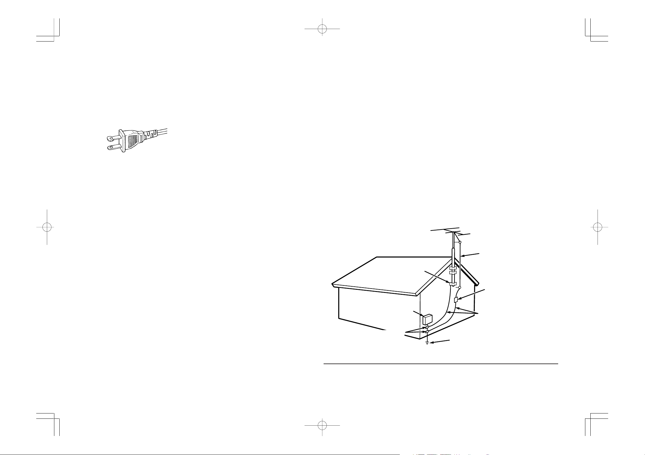
15. Outdoor Antenna Grounding – If an outside
antenna or cable system is connected to the
product, be sure the antenna or cable system
is grounded so as to provide some protection
against voltage surges and built-up static
charges. Article 810 of the National Electrical
Code, ANSI/NFPA 70, provides information
with regard to proper grounding of the mast
and supporting structure, grounding of the
lead-in wire to an antenna discharge unit, size
of grounding conductors, location of antennadischarge unit, connection to grounding
electrodes, and requirements for the
grounding electrode. See Figure 1.
16. Lightning – For added protection for this
product during a lightning storm, or when it is
left unattended and unused for long periods of
time, unplug it from the wall outlet and
disconnect the antenna or cable system. This
will prevent damage to the product due to
lightning and power-line surges.
17. Power Lines – An outside antenna system
should not be located in the vicinity of
overhead power lines or other electric light or
power circuits, or where it can fall into such
power lines or circuits. When installing an
outside antenna system, extreme care should
be taken to keep from touching such power
lines or circuits as contact with them might be
fatal.
18. Overloading – Do not overload wall outlets,
extension cords, or integral convenience
receptacles as this can result in a risk of fire or
electric shock.
19. Object and Liquid Entry – Never push objects
of any kind into this product through openings
as they may touch dangerous voltage points
or short-out parts that could result in a fire or
electric shock. Never spill liquid of any kind on
the product.
20. Servicing – Do not attempt to service this
product yourself as opening or removing
covers may expose you to dangerous voltage
or other hazards. Refer all servicing to
qualified service personnel.
21. Damage Requiring Service – Unplug this
product from the wall outlet and refer servicing
to qualified service personnel under the
following conditions:
a. When the power-supply cord or plug is
damaged.
b. If liquid has been spilled, or objects have
fallen into the product.
c. If the product has been exposed to rain or
water.
d. If the product does not operate normally by
following the operating instructions. Adjust
only those controls that are covered by the
operating instructions as an improper
adjustment of other controls may result in
damage and will often require extensive work
by a qualified technician to restore the product
to its normal operation.
e. If the product has been dropped or damaged
in any way, and
f. When the product exhibits a distinct change in
performance – this indicates a need for
service.
FIGURE 1
EXAMPLE OF ANTENNA GROUNDING AS PER
NATIONAL ELECTRICAL CODE, ANSI/NFPA 70
GROUND
CLAMP
ELECTRIC
SERVICE
EQUIPMENT
GROUND CLAMPS
NEC - NATIONAL ELECTRICAL CODE
22. Replacement Parts – When replacement
parts are required, be sure the service
technician has used replacement parts
specified by the manufacturer or have the
same characteristics as the original part.
Unauthorized substitutions may result in fire,
electric shock, or other hazards.
23. Safety Check – Upon completion of any
service or repairs to this product, ask the
service technician to perform safety checks to
determine that the product is in proper
operating condition.
24. Wall or Ceiling Mounting – The product should
be mounted to a wall or ceiling only as
recommended by the manufacturer.
25. Heat – The product should be situated away
from heat sources such as radiators, heat
registers, stoves, or other products (including
amplifiers) that produce heat.
ANTENNA
LEAD IN WIRE
ANTENNA
DISCHARGE UNIT
(NEC SECTION 810-20)
GROUNDING CONDUCTORS
(NEC SECTION 810-21)
POWER SERVICE GROUNDING
ELECTRODE SYSTEM
(NEC ART 250, PART H)
This Class B digital apparatus complies with
Canadian ICES-003.
SR5500UDFU00cover 04.8.2, 3:25 PMPage 2 AdobePageMaker6.5J/PPC
Cet appareil numérique de la Classe B est conforme
à la norme NMB-003 du Canada.
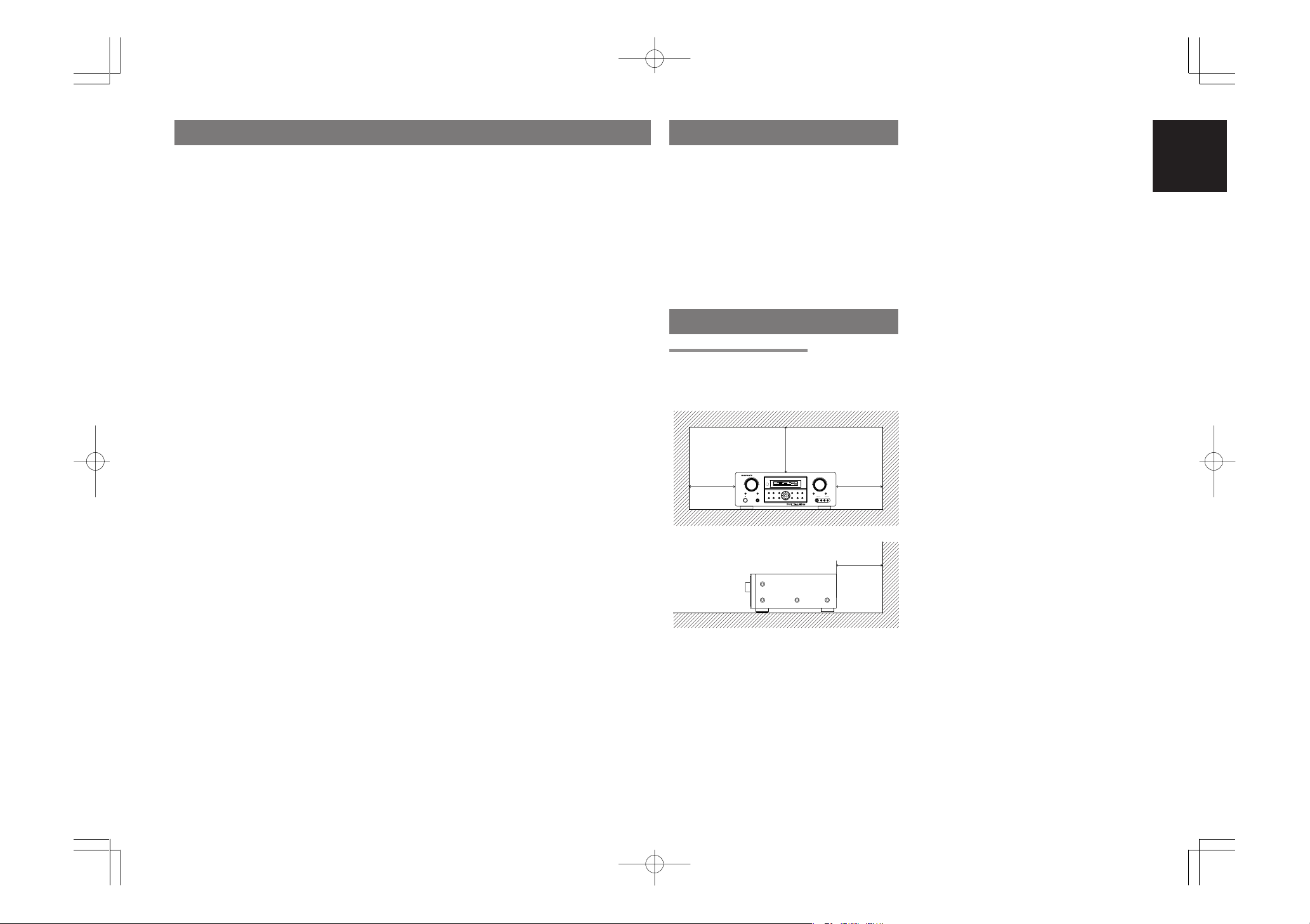
TABLE OF CONTENTS INTRODUCTION
20 cm (8 ins.)
20 cm (8 ins.)
SURROUND
AV SURROUND RECEIVER SR5500
DOWN
UP
VOLUME
INPUT SELECTOR
POWER ON / STANDBY PHONES
STANDBY
MUTE
MULTI
M. SPEAKER B
7.1CH INPUT
PURE
SETUP
DIRECT
SIMPLE
AUTO
HT-EQ
MENU
ENTER
DISPLAY
MEMORY
CLEAR
T-MODE
EXIT
BAND
MODE
DISPMULTI AUTO TUNED ST V – OFFNIGHT PEAK ANALOG
DIGITAL
ATT
SLEEP
SURR
AUTO
DIRECT DISC 6.1MT X 6.1 EQ
DIGITAL
SURROUND
PCM
LCR
SLS SR
LFE
AUX 1 INPUT
AUDIOS-VIDEO VIDEO L R
INTRODUCTION.................................. 1
PRECAUTIONS ................................... 1
DESCRIPTION..................................... 2
FEATURES .......................................... 3
ACCESSORIES ................................... 3
FRONT PANEL .................................... 4
FL DISPLAY ...................................................................... 5
REAR PANEL ...................................... 6
REMOTE CONTROL OPERATION ..... 7
FUNCTION AND OPERATION ......................................... 7
PROGRAMMING THE REMOTE CONTROLLER ............ 8
OPERATION OF REMOTE CONTROL UNIT ................... 9
GENERAL INFORMATION OF RC5500SR TO SR5500 .. 9
CONNECTIONS................................. 11
SPEAKER PLACEMENT ................................................ 11
CONNECTING SPEAKERS ............................................ 11
CONNECTING AUDIO COMPONENTS ......................... 12
CONNECTING VIDEO COMPONENTS ......................... 13
ADVANCED CONNECTING ........................................... 14
CONNECTING THE REMOTE CONTROL JACKS ........ 14
CONNECTING THE ANTENNA TERMINALS ................. 15
CONNECTING FOR THE MULTI ROOM ........................ 16
SETUP ............................................... 17
ON SCREEN DISPLAY MENU SYSTEM ........................ 17
1 INPUT SETUP (ASSIGNABLE DIGITAL INPUT AND
COMPONENT VIDEO INPUT) ..................................... 18
2 SPEAKER SETUP ...................................................... 18
3 PREFERENCE ............................................................ 19
4 SURROUND ............................................................... 20
II
(PRO LOGIC II) MUSIC PARAMETER .............. 20
5 PL
6 CS
II
(CIRCLE SURROUND II) PARAMETER .......... 20
7 MULTI ROOM.............................................................. 20
8 7.1 CH INPUT LEVEL ................................................. 21
SIMPLE SETUP ................................. 22
BASIC OPERATION (PLAY BACK) .. 23
SELECTING AN INPUT SOURCE .................................. 23
VIDEO CONVERT ........................................................... 23
SELECTING THE SURROUND MODE .......................... 23
ADJUSTING THE MAIN VOLUME .................................. 23
ADJUSTING THE TONE (BASS & TREBLE) CONTROL ...
TEMPORARILY TURNING OFF THE SOUND ............... 24
USING THE SLEEP TIMER ............................................ 24
NIGHT MODE ................................................................. 24
SURROUND MODE........................... 24
OTHER FUNCTION ........................... 27
TV AUTO ON/OFF FUNCTION ....................................... 27
ATTENUATION TO ANALOG INPUT SIGNAL ................ 27
LISTENING THROUGH HEADPHONES ........................ 27
DOLBY HEADPHONE MODE ......................................... 27
VIDEO ON/OFF .............................................................. 27
DISPLAY MODE .............................................................. 27
SELECTING ANALOG AUDIO INPUT OR
DIGITAL AUDIO INPUT ................................................ 28
RECORDING AN ANALOG SOURCE ............................ 28
HT-EQ ............................................................................. 28
7.1 CH INPUT ................................................................. 28
AUX2 INPUT ................................................................... 29
LIP.SYNC ........................................................................ 29
BASIC OPERATION (TUNER) .......... 29
LISTENING TO THE TUNER .......................................... 29
PRESET MEMORY ......................................................... 30
MULTI ROOM SYSTEM ..................... 32
MULTI ROOM PLAYBACK USING
THE MULTI ROOM OUT TERMINALS ........................ 32
MULTI ROOM PLAYBACK USING
THE MULTI SPEAKER TERMINALS ........................... 32
TROUBLESHOOTING....................... 33
TECHNICAL SPECIFICATIONS ....... 34
DIMENSIONS .................................... 34
Thank you for purchasing the Marantz SR5500
Surround receiver.
This remarkable component has been engineered
to provide you with many years of home theater
enjoyment. Please take a few minutes to read this
manual thoroughly before you connect and
operate the SR5500.
23
As there are a number of connection and configuration
options, you are encouraged to discuss your own
particular home theater setup with your Marantz A/V
specialist dealer.
PRECAUTIONS
CAUTIONS ON INSTALLATION
For heat dispersal, leave at least 20 cm/8 inch of
space between the top, back and sides of this unit
and the wall or other components.
• Do not obstruct the ventilation holes.
ENGLISH
SR5500UDFU01ENG12 04.8.2, 6:24 PMPage 1 AdobePageMaker6.5J/PPC
1
ENGLISH
DESCRIPTION
DTS was introduced in 1994 to provide 5.1 channels
of discrete digital audio into home theater systems.
DTS brings you premium quality discrete
multichannel digital sound to both movies and music.
DTS is a multichannel sound system designed to
create full range digital sound reproduction.
The no compromise DTS digital process sets the
standard of quality for cinema sound by delivering
an exact copy of the studio master recordings to
neighborhood and home theaters.
Now, every moviegoer can hear the sound exactly
as the moviemaker intended.
DTS can be enjoyed in the home for either movies
or music on of DVD’s, LD’s, and CD’s.
“DTS” and “DTS Digital Surround” are registered
trademarks of Digital Theater Systems, Inc.
The advantages of discrete multichannel systems
over matrix are well known.
But even in homes equipped for discrete
multichannel, there remains a need for high-quality
matrix decoding. This is because of the large library
of matrix surround motion pictures available on disc
and on VHS tape; and analog television broadcasts.
The typical matrix decoder of today derives a
center channel and a mono surround channel from
two-channel matrix stereo material. It is better than
a simple matrix in that it includes steering logic to
improve separation, but because of its mono,
band-limited surround it can be disappointing to
users accustomed to discrete multichannel.
Neo:6 offers several important improvements as
follow,
• Neo:6 provides up to six full-band channels of
matrix decoding from stereo matrix material.
Users with 6.1 and 5.1 systems will derive six
and five separate channels, respectively,
corresponding to the standard home-theater
speaker layouts.
•
Neo:6 technology allows various sound elements
within a channel or channels to be steered
separately, and in a way which follows naturally
from the original presentation.
•
Neo:6 offers a music mode to expand stereo
nonmatrix recordings into the five- or six-channel
layout, in a way which does not diminish the subtlety
and integrity of the original stereo recording.
2
DTS-ES Extended Surround is a new multichannel
digital signal format developed by Digital Theater
Systems Inc. While offering high compatibility with
the conventional DTS Digital Surround format,
DTS-ES Extended Surround greatly improves the
360-degree surround impression and space
expression thanks to further expanded surround
signals. This format has been used professionally
in movie theaters since 1999.
In addition to the 5.1 surround channels (FL, FR, C,
SL, SR and LFE), DTS-ES Extended Surround
also offers the SB (Surround Back) channel for
surround playback with a total of 6.1 channels.
DTS-ES Extended Surround includes two signal
formats with different surround signal recording
methods, as DTS-ES Discrete 6.1 and DTS-ES
Matrix 6.1.
“DTS”, “DTS-ES” and “Neo:6” are trademarks of
Digital Theater Systems, Inc.
The stereo CD is a 16-bit medium with sampling at
44.1 kHz. Professional audio has been 20- or 24bit for some time, and there is increasing interest in
higher sampling rates both for recording and for
delivery into the home. Greater bit depths provide
extended dynamic range. Higher sampling rates
allow wider frequency response and the use of
anti-alias and reconstruction filters with more
favorable aural characteristics.
DTS 96/24 allows for 5.1channel sound tracks to
be encoded at a rate of 96kHz/24bits on DVDVideo titles.
When DVD-video appeared, it became possible to
deliver 24-bit, 96 kHz audio into the home, but only
in two channels, and with serious limitations on
picture. This capability has had little use.
DVD-audio allows 96/24 in six channels, but a new
player is needed, and only analog outputs are
provided, necessitating the use of the D/A
converters and analog electronics provided in the
player.
DTS 96/24 offers the following:
1. Sound quality transparent to the original 96/24
master.
Full backward compatibility with all existing
2.
decoders. (Existing decoders will output a 48 kHz
signal)
3.No new player required: DTS 96/24 can be
carried on DVD-video, or in the video zone of
DVD-audio, accessible to all DVD players.
4. 96/24 5.1-channel sound with full-quality fullmotion video, for music programs and motion
picture soundtracks on DVD-video.
“DTS” and “DTS 96/24” are trademarks of Digital
Theater Systems, Inc.
Dolby Digital identifies the use of Dolby Digital
audio coding for such consumer formats as DVD
and DTV. As with film sound, Dolby Digital can
provide up to five full-range channels for left,
center, and right screen channels, independent left
and right surround channels, and a sixth (“.1”)
channel for low-frequency effects.
Dolby Surround Pro Logic II is an improved matrix
decoding technology that provides better spatiality
and directionality on Dolby Surround program
material; provides a convincing three-dimensional
soundfield on conventional stereo music
recordings; and is ideally suited to bring the
surround experience to automotive sound. While
conventional surround programming is fully
compatible with Dolby Surround Pro Logic II
decoders, soundtracks will be able to be encoded
specifically to take full advantage of Pro Logic II
playback, including separate left and right
surround channels. (Such material is also
compatible with conventional Pro Logic decoders.)
Dolby Digital EX creates six full-bandwidth output
channels from 5.1-channel sources. This is done
using a matrix decoder that derives three surround
channels from the two in the original recording.
For best results, Dolby Digital EX should be used
with movies soundtracks recorded with Dolby
Digital Surround EX.
About Dolby Pro Logic
Dolby Pro Logic II x technology delivers a natural
and immersing 7.1-channel listening experience to
the home theater environment. A product of
Dolby’s expertise in surround sound and matrix
decoding technologies, Dolby Pro Logic IIx is a
complete surround sound solution that maximizes
the entertainment experience from stereo as well
as 5.1-channel encoded sources.
II x
Dolby Pro Logic II x is fully compatible with Dolby
Surround Pro Logic technology and can optimally
decode the thousands of commercially available
Dolby Surround encoded video cassettes and
television programs with enhanced depth and
spatiality. It can also process any high-quality
stereo or Advanced Resolution 5.1-channel music
content into a seamless 6.1- or 7.1-channel
listening experience.
The Dolby Headphone technology provides a
surround sound listening experience over headphones.
When listening to multichannel content such as
DVD movies over headphones, the listening
experience is fundamentally different than
listening to speakers. Since the headphone
speaker drivers are covering the pinna of the ear,
the listening experience differs greatly from
traditional speaker playback. Dolby utilizes
patented headphone perspective curves to solve
this problem and provides a non-fatiguing,
immersive, home theater listening experience.
Dolby Headphone also delivers exceptional 3D
audio from stereo material.
Manufactured under license from Dolby
Laboratories. “Dolby”, “Pro Logic”, and the doubleD symbol are trademarks of Dolby Laboratories.
Circle Surround II (CS-II ) is a powerful and
versatile multichannel technology. CS-II is
designed to enable up to 6.1 multichannel
surround sound playback from mono, stereo, CS
encoded sources and other matrix encoded
sources. In all cases the decoder extends it into 6
channels of surround audio and a LFE/subwoofer
signal. The CS-II decoder creates a listening
environment that places the listener “inside” music
performances and dramatically improves both hi-fi
audio conventional surround-encoded video
material. CS-II provides composite stereo rear
channels to greatly improve separation and image
positioning – adding a heightened sense of realism
to both audio and A/V productions.
SR5500UDFU01ENG12 04.8.2, 4:11 PMPage 2 AdobePageMaker6.5J/PPC
CH.SEL
LIP.SYNC
PTY
S
UB-T/ATT
AUD
IO
INPUT/DISC+
F.DIRE
CT
RDS
TUNE/SEARCH
T-MOD
E
TREBLE
CHA
NNEL/
SK
IP
BASS
A/D
P.SCAN/V-OFF
7.1CH
IN
STER
EO
MC
H-ST
MEMO
CLEAR
DISPLAY
NIGHT
CSII
EX/ES
VIRTUAL
DTS
S-D
IR
EC
T
AUTO
T.TO
NE
M
ENU
O
FF
SETUP/
MENU
O
SD
SLEEP
MUTE
AMP
AUX
1
TUNER
CD
TAPE
CDR/M
D
DVD
POWER
VCR1
DS
S/VCR
2
TV
SYSTEM REMOTE CONTROLLER
RC5500SR
ENTER
0
321
654
9
8
7
VOL.
MAIN
VOL.
TV
PUSH
PUSH
CS-II is packed with other useful feature like dialog
clarity (SRS Dialog) for movies and cinema-like
bass enrichment (TruBass). CS-II can enable the
dialog to become clearer and more discernable in
movies and it enables the bass frequencies
contained in the original programming to more
closely achieve low frequencies – overcoming the
low frequency limitations of the speakers by full
octave.
Circle Surround II , Dialog Clarity, TruBass, SRS
and symbol are trademarks of SRS Labs,
Inc.
Circle Surround II , Dialog Clarity and TruBass
technology are incorporated under license from
SRS Labs, Inc.
FEATURES
The SR5500 incorporates the latest generation of
digital surround sound decoding technology such
as Dolby Digital EX, Dolby Digital, DTS-ES
(Discrete 6.1 and Matrix 6.1), DTS Neo:6 (Cinema,
Music), Dolby Pro-Logic IIx (Movie, Music and
Game), Circle Surround II (Cinema and Music) .
In addition, Marantz has focused on the future. By
utilizing pre-out jacks, 7.1 direct inputs and a RS232C communication port, the SR5500 is
tomorrow’s technology, today!
The SR5500 features a fully discrete 7 channel
amplifier section capable of delivering 90 watts of
high-current amplification, for continuously clean
and stable power into each of the 7 channels. It
employs a massive EI power transformer in
combination with oversized filter capacitors.
Current feedback topology allows total operation
stability, while requiring minimal amounts of
negative feed-back, resulting in an excellent
transient frequency response and superb sonic
transparency. This design configuration is capable
of a clear and powerful reproduction of the most
demanding action movie soundtracks and full
range (multichannel) music discs. Through its
ability to generate very high output voltages, the
SR5500 can easily drive the most demanding
speakers with optimum results.
The SR5500 incorporates the most advanced
Digital Signal Processing circuitry, along with a
®
Crystal
192 kHz/24 bit D/A converter in each of
the 8 channels. Independent power supply circuits
are incorporated for the FL display, audio and
video sections for maximum separation, clarity
and dynamic range. Together with hand-selected
customized components, all elements work in
harmony to recreate the emotion, exactly as the
artist had intended.
The SR5500 is designed and engineered with
extensive feedback from custom installation
experts, dealers and consumers. It features multiroom/multisource, a RS-232C communication
port, heavy duty speaker binding posts and an
extensive array of both analog and digital inputs /
outputs. With 4 assignable digital inputs, 2
assingnable component inputs, SACD Multi
Channel (7.1 channel) direct inputs video convert
system and OSD output versatility is taken to a
stunning new level. Furthermore, the SR5500 can
output the OSD information through the Y/C (Svideo) and composite video outputs.
An easy-to-use universal remote control allows full
access to all of the operating functions and can be
used for system operation as well.
This unit has Simple Setup function for easy setup.
You can setup all speaker settings by just selecting
your room size and the number of your speakers
with Simple Setup function. You can also setup
customized settings just like conventional AV
amplifiers.
• Dolby Digital EX, Dolby Digital ,
DTS ES (Discrete 6.1, Matrix 6.1, Neo: 6)
• Dolby Headphone (DH1, DH2, DH3)
• Dolby Pro Logic II x (Movie, Music, Game)
• Circle Surround II (Movie, Music, Mono)
• 7 x 90 Watts (8 Ohm), Discrete Amplifiers
• High Power Current Feedback Circuitry
• Massive Energy Power Supply, Huge EI
Transformer, Large ELCO’s.
• 192 kHz/24 bit Crystal® DAC for all 8 Channels
• 32 bit Digital Surround Processing Chipsets
• Video Off Mode
• Large Heavy Duty Speaker Terminals for all
Channels
• RS-232C Terminal for System Control
• Set Up Menu via all Video Output (Composite,
S-Video and Component video)
• Auto Input Signal Detection
• Improved Station Name Input Method, 50
Presets
• Auto Adjust Function for Speaker Distance
Settings (Delay Time)
• Front AUX Input (Digital Camera, Portable DVD)
• Universal remote control
• Simple Setup Function
• Video convert system
• LIP.SYNC Funciton (Audio delay)
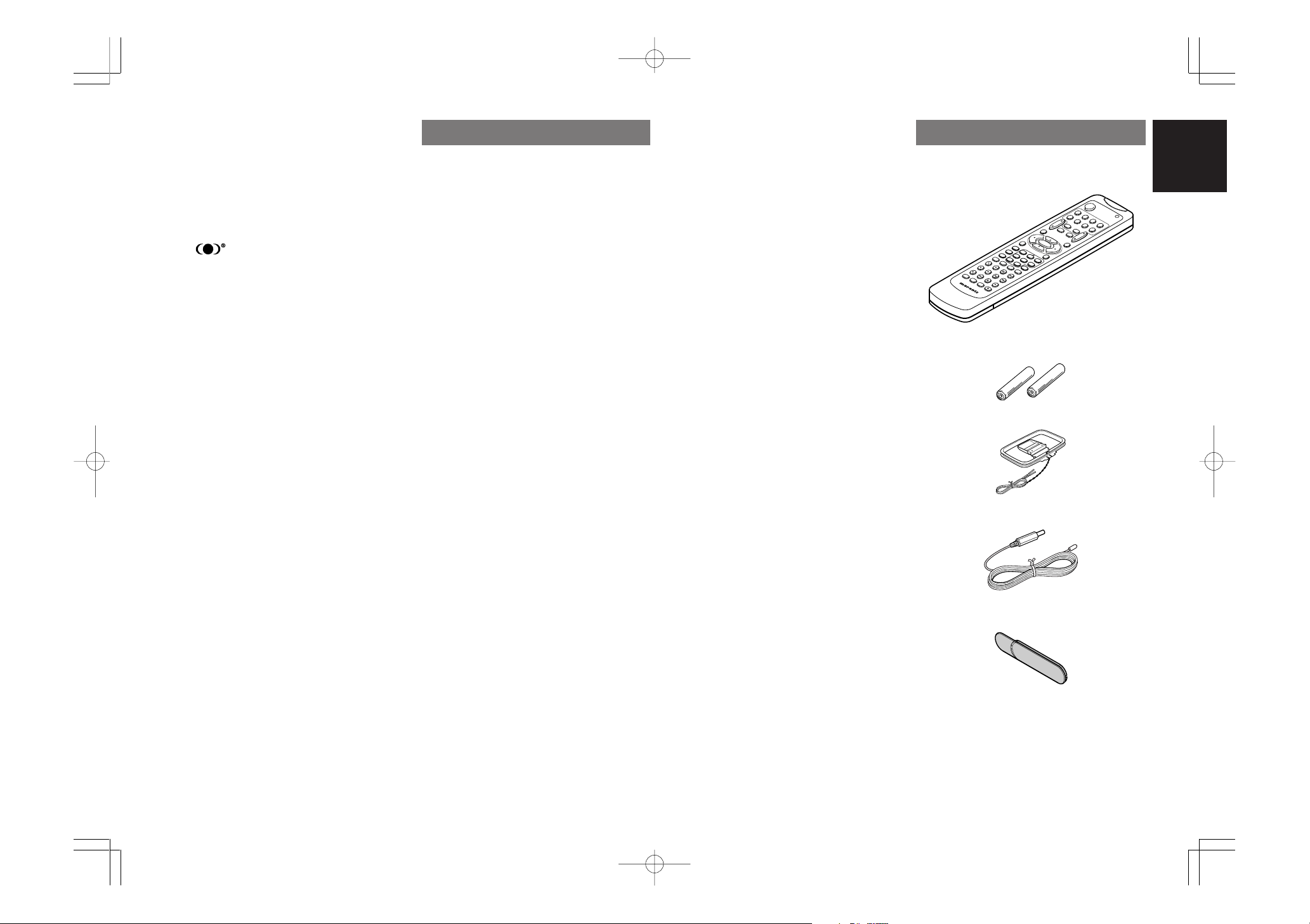
ACCESSORIES
Remote Controller RC5500SR
ENGLISH
AAA-size batteries X 2
AM Loop Antenna
FM Antenna
Front AUX Jack Cover
User Guide
SR5500UDFU01ENG12 04.8.2, 4:11 PMPage 3 AdobePageMaker6.5J/PPC
3
SURROUND
AV SURROUND RECEIVER SR5500
DOWN
UP
VOLUME
INPUT SELECTOR
POWER ON / STANDBY PHONES
STANDBY
MUTE
MULTI
M. SPEAKER B
7.1CH INPUT
PURE
SETUP
DIRECT
SIMPLE
AUTO
HT-EQ
MENU
ENTER
DISPLAY
MEMORY
CLEAR
T-MODE
EXIT
BAND
MODE
DISP MULTI AUT O TUNED ST V – OFF NIGHT PEAK ANALOG
DIGITAL
ATT
SLEEP
SURR
AUTO
DIRECT DISC 6.1 MTX 6.1 EQ
DIGITAL
SURROUND
PCM
LCR
SL S SR
LFE
AUX 1 INPUT
AUDIOS-VIDEO VIDEO L R
!5!6!7!8 @3!9@0@1@2
qw yu !3io!0t!2!1re
!4
ENGLISH
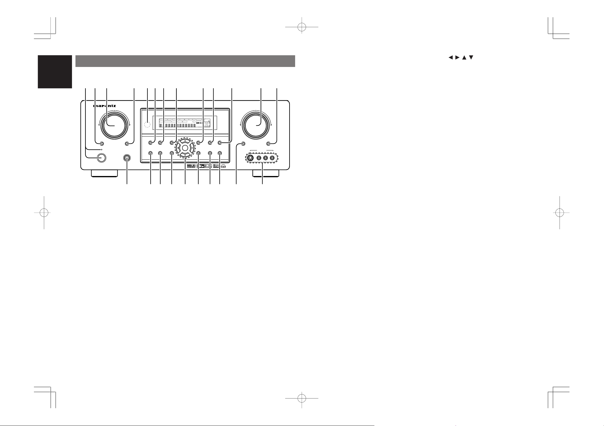
FRONT PANEL
q
POWER switch and STANDBY indicator
When this switch is pressed once, the unit turns ON
and the display illuminates. When pressed again,
the unit turns OFF and the STANDBY indicator will
be illuminated.
w
MULTI (Multi Room) button
Press this button to activate the Multiroom system.
“MULTI” indicator will be illuminated in the display.
e
INPUT SELECTOR knob (AUDIO/ VIDEO)
This knob is used to select the input sources.
The video function selector, such as TV, DVD, VCR1
and DSS, selects video and audio simultaneously.
Audio function sources such as CD, TAPE, CDR/
MD, and TUNER may be selected in conjunction
with a Video source.
This feature (Sound Injection) combines a sound
from one source with a picture from another.
Choose the video source first, and then choose a
different audio source to activate this function.
r
M.(Multi Room) SPEAKER B button
Press this button to activate the Multiroom Speaker
B system. “MULTI” indicator will be illuminated in
the display.
(See page 32)
t
INFRARED receiving sensor window
This window receives infrared signals for the
remote control.
y
SURROUND MODE button
You can select the surround mode by pressing this
button.
u
PURE DIRECT button
When this button is pressed, the tone control
circuitry is bypassed as well as Bass Management.
“DIRECT” indicator will be illuminated in the
display.
Notes:
• The surround mode is automatically switched to
AUTO when the pure direct function is turned on.
• Additionally, Speaker Configurations are fixed
automatically as follows.
Front SPKR = Large, Center SPKR = Large,
Surround SPKR = Large, Sub woofer = On
• This function is unavailable when the M. speaker
B system is activated. While this function is
activated, this function will be canceled if the M.
SPEAKER B button is pressed.
i
SIMPLE SETUP button
Press this button to enter the simple setup mode.
You can setup the speaker conditions (speaker
sizes, number of speakers, speaker delay times)
quickly by pressing the cursor buttons.
o
DISPLAY button
When this button is pressed, the FL display mode
is changed as Surround Mode → Auto-display Off
→ Display Off → Input Function and the display off
indicator(DISP) lights up in condition of DISPLAY
OFF.
!0
MEMORY button
Press this button to enter the tuner preset memory
numbers or station names. (See page 30)
!1
CLEAR button
Press this button to cancel the station-memory
setting mode or preset scan tuning. (See page 30)
!2
VOLUME control knob
Adjusts the overall sound level. Turning the control
clockwise increases the sound level.
!3
7.1CH INPUT button
Press this button to select the output of an external
multichannel player.
!4
MUTE button
Press this button to mute the output to the
speakers. Press it again to return to the previous
volume level.
!5
T-MODE button
Press this button to select the auto stereo mode or
mono mode when the FM band is selected.
The “AUTO” indicator lights in the auto stereo
mode. (See page 30)
!6
BAND button
Press this button to switch between FM and AM in
the TUNER mode.
!7
EXIT button
This button is used to exit from the SETUP MAIN
MENU.
!8
Cursor ( , , , ) / ENTER button
Use these buttons when operating the SETUP
MAIN MENU and TUNER function.
!9
MENU button
This button is used to enter the SETUP MAIN
MANU.
@0
HT-EQ button
Used to turn on or off HT(Home Theater)-EQ
mode. This mode compensates for the audio
portion of a movie sounding “bright”. When this
button is pressed, “EQ” indicator lights up.
@1
AUTO (Auto surround) button
Press this button to select the AUTO mode from the
surround modes. When this mode is selected, the
receiver determines the surround mode
corresponding to a digital input signal automatically.
@2
HEADPHONE jack for stereo headphones
This jack may be used to listen to the SR5500’s
output through a pair of headphones. Be certain
that the headphones have a standard 1 / 4” stereo
phono plug. Note that the main room speakers will
automatically be turned off when the headphone
jack is in use.
Notes:
• When using headphones, the surround mode will
change to STEREO and Dolby Headphone by
MENU and Cursor button.
• The surround mode returns to the previous setting
as soon as the headphone plug is removed from
the jack.
@3
AUX1 INPUT jacks
These auxiliary video/audio input jacks accept the
connections of a camcorder, portable DVD, game
etc.
4
SR5500UDFU01ENG12 04.8.2, 4:12 PMPage 4 AdobePageMaker6.5J/PPC
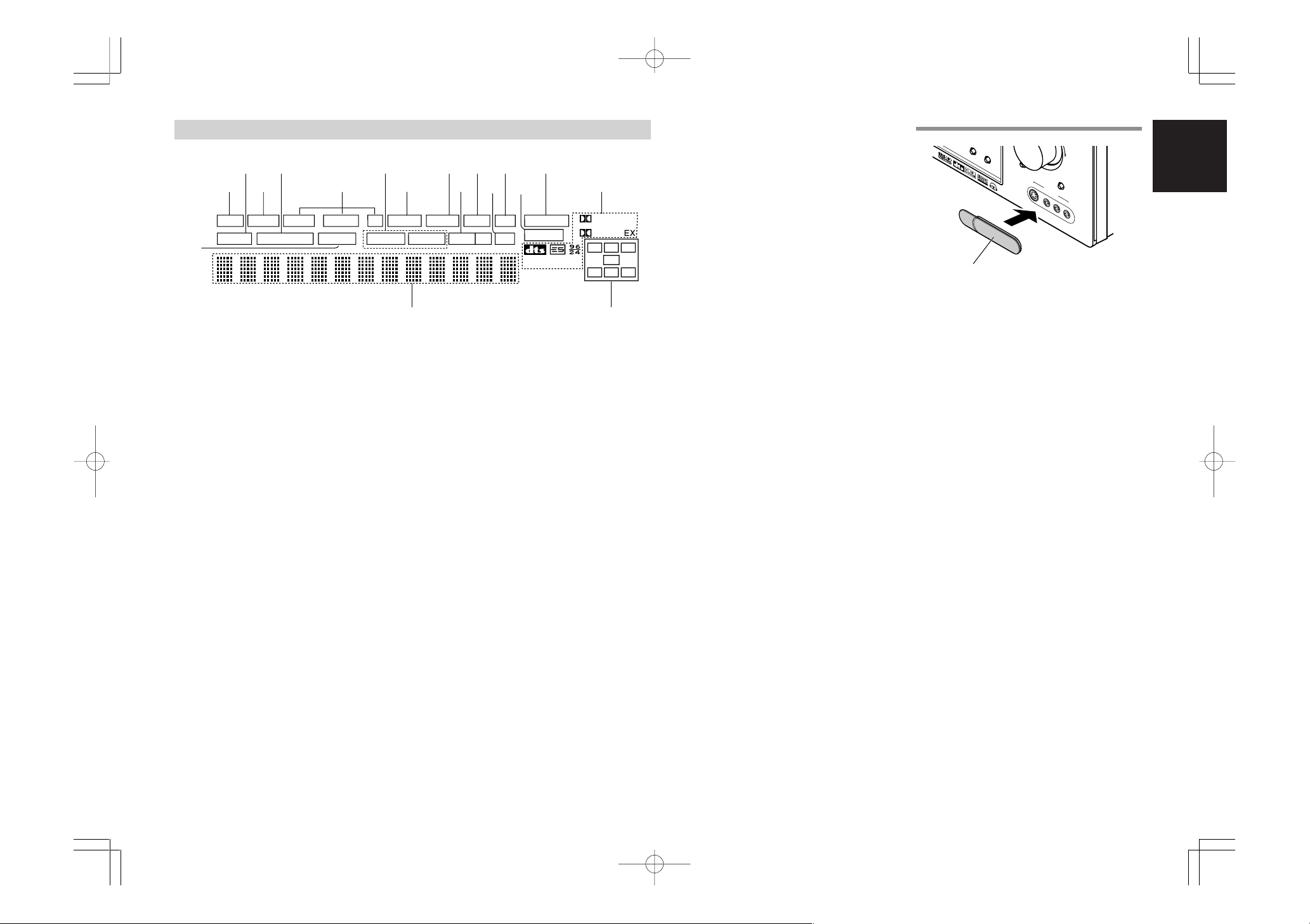
FL DISPLAY
DISP MULTI AU TO TUNED ST V – OFF NIGHT PEAK ANALOG
DIGITAL
ATT
SLEEP
SURR
AUTO
DIRECT DISC 6.1 MTX 6.1 SPKR B EQ
DIGITAL
SURROUND
PCM
L
C
R
SL S SR
LFE
¡8
¡7
g
s
a
¡6
h k¡0¡2 ¡4f
j l ¡1
¡3
¡5d
ND
a
DISP (Display Off) indicator
This indicator is illuminated when the SR5500 is in
the display off condition.
s
SLEEP timer indicator
This indicator is illuminated when the sleep timer
function in the main-room is in use.
d
Multi-room system indicator
This indicator is illuminated when the multi-room
system is active.
f
AUTO SURR (Auto Surround mode)
indicator
This indicator is illuminated to show that the AUTO
SURROUND mode is in use.
g
TUNER’s indicators
AUTO : This indicator illuminates when the
TUNED : This indicator illuminates when a
ST(Stereo) : This indicator illuminates when an
tuner’s Auto mode is in use.
station is being received with
sufficient signal strength to provide
acceptable listening quality.
FM station is being tuned into
stereo condition.
j
V (video)-OFF mode indicator
This indicator is illuminated when the Video-OFF
function is active.
k
NIGHT mode indicator
This indicator is illuminated when the SR5500 is in
the Night mode, which reduces the dynamic range
of digital program material at low volume levels.
l
SPKR (speaker) B indicator
This indicator is illuminated when the M (Multiroom)
speaker B system is active.
¡0
PEAK indicator
This indicator is a monitor for an analog audio input
signal. If the selected analog audio input signal is
greater than the capable level of internal
processing, this will illuminate. If this happens, you
should press the ATT button on the remote.
¡1
EQ mode indicator
This indicator is illuminated when the HT-EQ
function is active.
¡2
ATT (Attenuation) indicator
This indicator is illuminated when the attenuation
function is active.
¡4
ANALOG input indicator
This indicator is illuminated when an analog input
source has been selected.
¡5
SIGNAL FORMAT indicators
2 DIGITAL, EX, 2 SURROUND, dts, ES, 96/24,
PCM
When the selected input is a digital source, some
of these indicators will be illuminated to display the
specific type of signal in use.
¡6
ENCODED CHANNEL STATUS
indicators
These indicators display the channels that are
encoded with a digital
input signal. If the selected digital input signal is
Dolby Digital 5.1ch or DTS 5.1ch, “L”, “C”, “R”,
“SL”, “SR” and “LFE” will be illuminated.If the
digital input signal is 2 channel PCM-audio, “L” and
“R” will be displayed.
If Dolby Digital 5.1ch signal with Surround EX flag
or DTS-ES signal comes in, “L”, “C”, “R”, “SL”, “S” ,
“SR” and “LFE” will be illuminated.
¡7
Main Information Display
This display shows messages relating to the
status, input source, surround mode, tuner,
volume level or other aspects of unit’s operation.
¡8
DIRECT (Puredirect) indicator
This indicator is illuminated when the SR5500 is in
the PURE DIRECT mode.
HOW TO ATTACH THE FRONT AUX JACK COVER
T-M
OD
E
PUSH
PUSH
Front AUX Jack Cover
MUTE
UP
7.1CH INPUT
S-VIDEO
AUX 1 INPUT
VIDEO
L
AUDIO
R
ENGLISH
h
DTS-ES mode indicators
(DISC6.1, MTX6.1)
These indicators will illuminate to show the DTSES decoding mode (Discrete 6.1 or Matrix 6.1).
SR5500UDFU01ENG12 04.8.2, 4:12 PMPage 5 AdobePageMaker6.5J/PPC
¡3
DIGITAL Input Indicator
This indicator lights when a digital input has been
selected.
5
AMGND
ANTENNA
COMPONENT VIDEO
M.SPEAKER B
LL
SURROUNDCENTERFRONT
RRLR
SURROUND BACK
FM (75
Ω
)
CB
/
PB
CR
/
PR
CR
/
PR
CR
/
PR
CB
/
PB
CB
/
PB
INPUT-1
YY
MONITOR OUTINPUT-2
Y
COAX.
4
2
OPT.
1
3
DIGITAL OUT
DIGITAL IN
MONITOR
(AUX2)
OUTTV
VCR1
MONITOR
VIDEO
OUTIN
IN OUT
TAPE CDR/MD
OUT
SW
OUTIN
CD SBL
SBR
SLL
INOUT
IN
7.1CH
AUDIO
SR
IN
RC-5
SWR
IN
R
TV DVD DSS/VCR2
RSR
LSL
PRE
OUT
SBL
SBR
L
VCR1
VCR1
OUTOUTIN
DSS/VCR2
OUTIN
MULTI
OUT
RC
RS-232C
C
DSS/VCR2
DVD
S-VIDEO
OUTIN
C
DVDTV
OUT
MULTI
SPEAKER SYSTEMS : MINIMUM 6 OHMS
MODEL NO. SR5500MODEL NO. SR5500
SWITCHED UNSWITCHED
1A 120W MAX
AC OUTLETS
120V 60H
Z
1A 120W MAX
AC IN
!0
!4
!3 !2 !1
tqw r yeui
!6 !5
o
ENGLISH
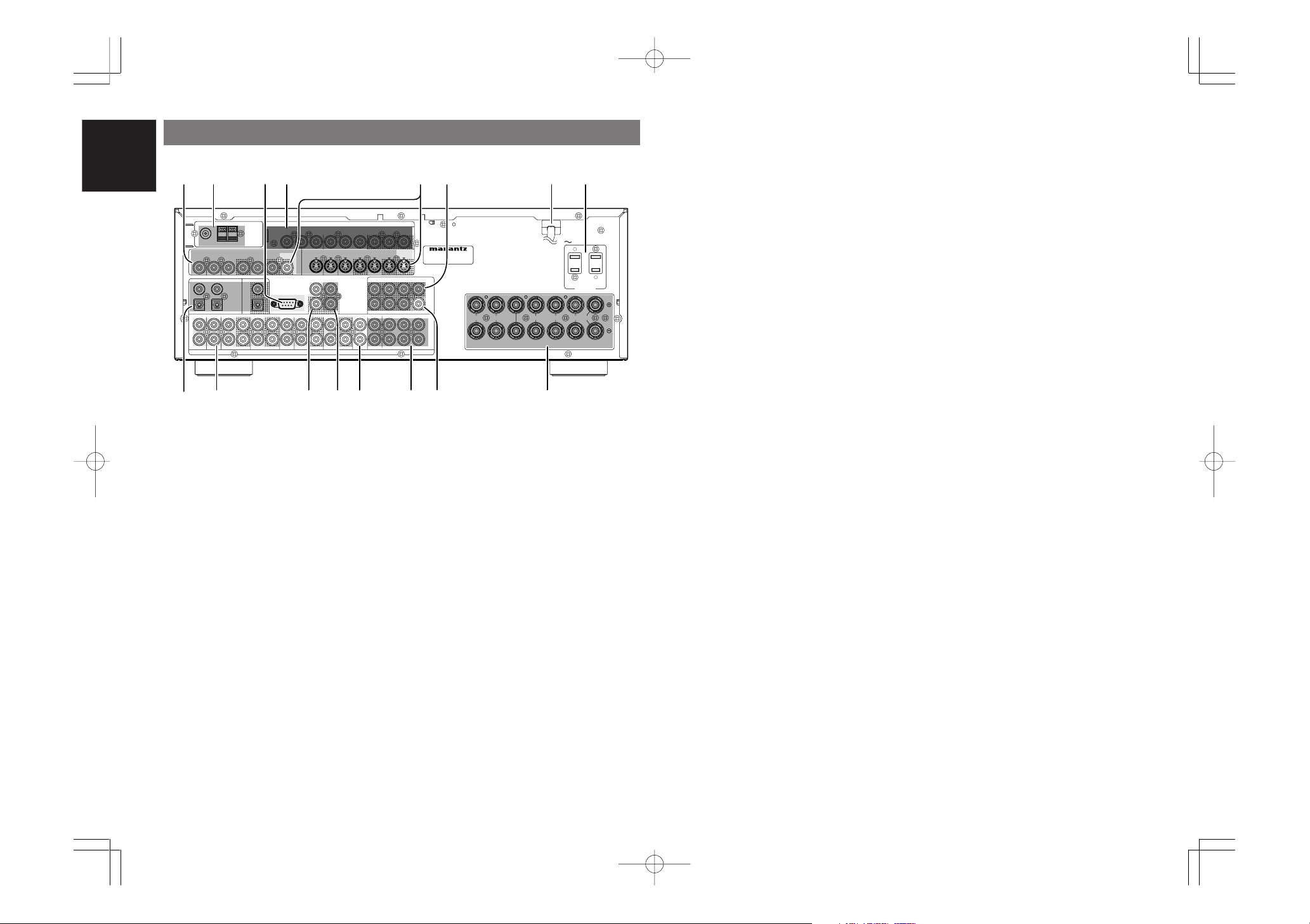
REAR PANEL
q
These are the video inputs and outputs. There are
4 video inputs and 2 video outputs and each one
includes both composite video and S-video
configurations. Connect VCRs, DVD players, and
other video components to the video inputs.
The 2 video output channels can be used to be
connected to video tape recorders for making
recordings.
The input signals of video and S-video are
converted each other, and each of the converted
video signals can be output.
w
Connect an external FM antenna with a coaxial
cable, or a cable network FM source.
Connect the supplied AM loop antenna. Use the
terminals marked “AM” and “GND”. The supplied
AM loop antenna will provide good AM reception in
most areas. Position the loop antenna until you
hear the best reception.
e
The RS-232C port is to be used in conjunction with
an external controller to control the operation of the
SR5500 by using an external device.
6
SR5500UDFU01ENG12 04.8.2, 4:12 PMPage 6 AdobePageMaker6.5J/PPC
VIDEO IN/OUT (TV, DVD, VCR1, DSS/VCR2)
FM antenna terminal (75 ohms)
AM antenna and ground terminals
RS-232C
r
COMPONENT VIDEO INPUT/OUTPUT
If your DVD player or other device has component
video connectors, be sure to connect them to
these component video connectors on the
SR5500. The SR5500 has two component video
input connectors to obtain the color information (Y,
CB, CR) directly from the recorded DVD signal or
other video component and one component video
output connector to output it directly into the matrix
decoder of the display device.
By sending the pure DVD component video signal
directly, the DVD signal forgoes the extra
processing that normally would degrade the
image. The result is vastly increased image
quality, with incredibly life like colors and crisp
detail.
When the video convert function is enabled, video
and S-video images can be output to the
COMPONENT MOINTOR OUT jack.
t
MONITOR OUT
This is a monitor output and each one includes
both composite video and S-video configurations.
When connecting two video monitors or
televisions, be aware that the OSD interface can
be used with both MONITOR OUT connections.
y
Preamp Outputs
(L, R, SL, SR, SBL, SBR, C)
Jacks for L(front left), R (front right), C (Center), SL
(surround left), SR (surround right), SBL (surround
back left) and SBR (surround back right).
Use these jacks for connection to external power
amplifiers.
u
Power cable
Connect to an AC power outlet.
SR5500 has to be powered by 120 V AC only.
i
AC OUTLETS
Connect the AC power cables of components such as
a DVD and CD player to these outlets. SWITCHED
and UNSWITCHED outlets are provided.
The one marked SWITCHED provides power only
when the SR5500 is turned on and is useful for
components which you use every time you play
your system.
The one marked UNSWITCHED is always live as
long as the SR5500 is plugged into a live outlet.
A component connected here may be left on
permanently, or may be switched off with via its
own power switch.
Caution:
•
In order to avoid potential turn-off thumps,
anything plugged into these outlets should be
powered up before the SR5500 is turned on.
•
The capacity of this AC outlet is 120W. Do not
connect devices that consume electricity more than
the capacity of these AC outlets. If the total power
consumption of the connected devices exceeds the
capacity, the protection circuit shuts down the
power supply.
o
Speaker outputs terminals
Seven terminals are provided for the front left, front
right, front center, surround left, surround right,
surround back left and surround back right speakers.
Note:
• You can use surround back speaker terminals as
M (Multiroom) SPEAKER B terminals, when you
use no surround back speaker.
!0
Subwoofer Output
Connect this jack to the line level input of a
powered subwoofer. If an external subwoofer
amplifier is used, connect this jack to the
subwoofer amplifier input. If you are using two
subwoofers, either powered or with a 2 channel
subwoofer amplifier, connect a “Y” connector to
the subwoofer output jack and run one cable from
it to each subwoofer amplifier.
!1
7.1 CHANNEL or AUX2 INPUT
By connecting a DVD Audio player, SACD
multichannel player, or other components that has
a multichannel port, you can playback the audio
with 5.1 channel or 7.1 channel outputs.
!2
Multiroom Outputs (Audio L&R)
These are the audio output jacks for the Multi zone
(Multi room).
Connect these jacks to optional audio power
amplifiers to listen the source selected by the
multiroom system in a remote room.
!3
MULTI ROOM REMOTE IN/OUT terminals
IN: Connect to a multi-room remote control
device, available from your Marantz dealer.
OUT: Connect to the Marantz component
equipped with remote control (RC-5)
terminals in Multi zone (Multi room).
!4
REMOTE CONT. IN/OUT terminals
Connect to a Marantz component equipped with
remote control (RC-5) terminals.
!5
AUDIO IN/OUT (CD, TAPE, CD-R, TV,
DVD, VCR1, DSS/VCR2)
These are the analog audio inputs and outputs.
There are 7 audio inputs (4 of which are linked to
video inputs) and 4 audio outputs (2 of which are
linked to video outputs). The audio jacks are
nominally labeled for cassette tape decks,
compact disc players, DVD players and etc.... The
audio inputs and outputs require RCA-type
connectors.
!6
DIGITAL INPUT (Dig.1 - 4) / OUTPUT
(coaxial, optical)
These are the digital audio inputs and outputs.
There are 2 digital inputs with coaxial jacks, 2 with
optical jacks.
The inputs accept digital audio signals from a
compact disc, LD, DVD, or other digital source
component.
For digital output, there is 1 coaxial output and 1
optical output.
The digital outputs can be connected to MD
recorders, CD recorders, DAT decks, or other
similar components.
ENTER
CH.SEL LIP.SYNC
PTY
SUB-T/ATT
AUDIO
INPUT/DISC+
F.DIRECT
RDS
TUNE/SEARCH
T-MODE
TREBLE
CHANNEL/SKIP
BASS
A/D
P.SCAN/V-OFF
7.1CH IN
STEREO
MCH-ST
MEMO
CLEAR
DISPLAY
NIGHT
CSII EX/ES VIRTUAL
DTS
PURE DIRECT
AUTO
321
654
9807
T.TONE
MENU OFF
SET UP/
MENU
OSD
VOL.
TV
VOL.
MAIN
SLEEP
MUTE
AMPAUX1
TUNER
CD
TAPE
CDR/MD
DVD
POWER
VCR1
DSS/VCR2
TV
SYSTEM REMOTE CONTROLLER
RC5500SR
,
m
n
b
v
c
x
z
⁄1
⁄2
⁄5
¤3
¤2
¤1
¤0
⁄9
⁄8
⁄7
⁄6
¤4
⁄4
⁄3
¤5
.
⁄0
m
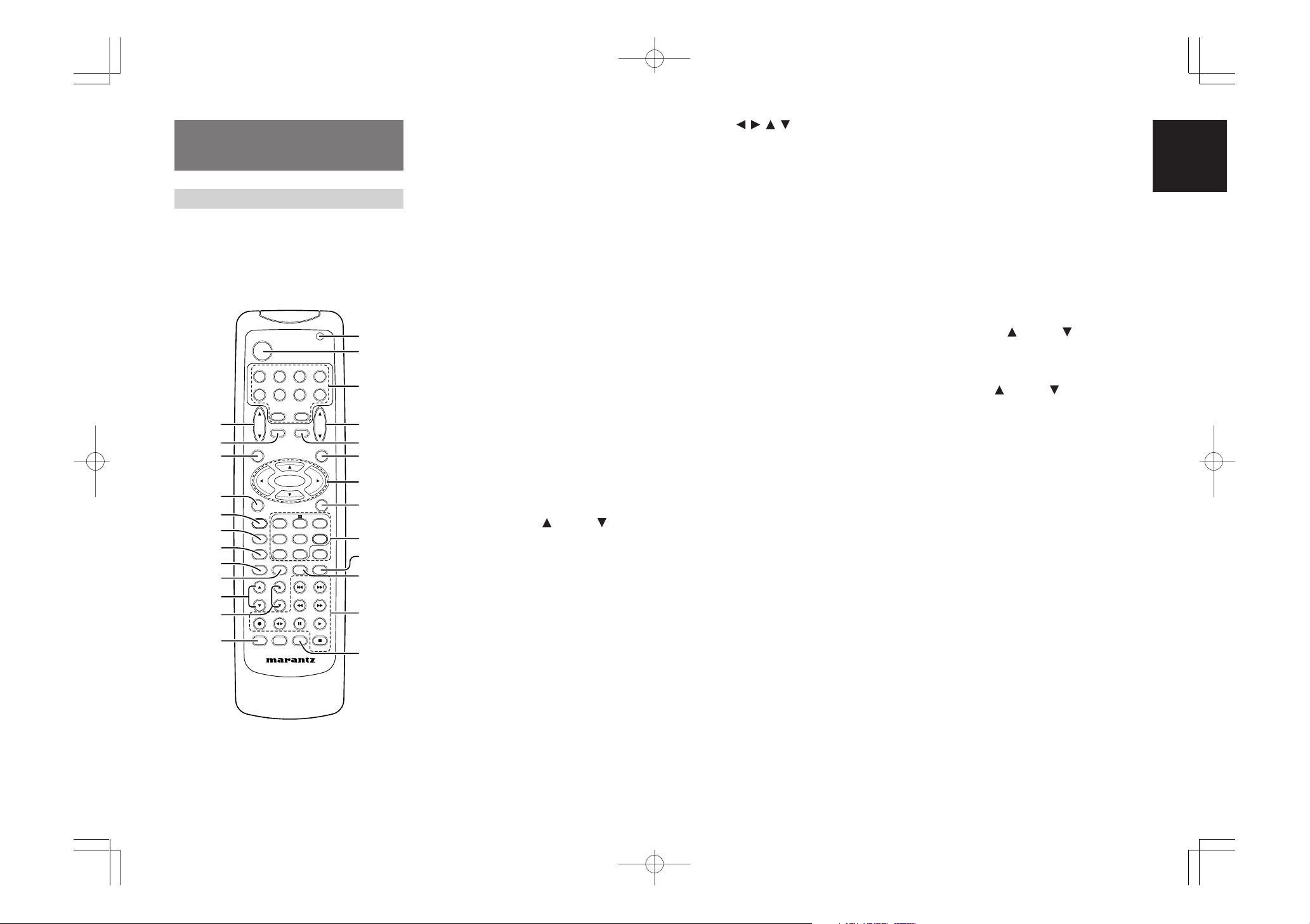
REMOTE CONTROL
OPERATION
FUNCTION AND OPERATION
The provided remote control unit is a universal
remote controller. The POWER button, numeric
buttons and control buttons are used in common
across different input source components.
The input source controlled with the remote control
unit changes when one of the input selector
buttons is pressed.
z
Transmitting indicator
Lights up during a button is pressed and an infrared
signal is sending.
x
(Main) POWER buttons
(when AMP mode is selected)
Press to switch the power of the SR5500 ON or OFF
after pressing the AMP button.
c
Input selector buttons/ FUNCTION
SELECTOR buttons (AUDIO/VIDEO INPUT)
These buttons are used to select a Audio or Video
source component. Press one of these buttons once
to change the function of the remote control. Press
same button within 2 seconds, the input function of
the SR5500 is changed.
Audio function sources such as CD, TAPE, CDR/
MD, and TUNER may be selected in conjunction
with a Video source.
This feature (Sound Injection) combines a sound
from one source with a picture from another.
Choose the video source first, and then choose a
different audio source to activate this function.
Notes:
• CDR/MD button is set CDR function at initial.
To switch MD function, press and hold down
CDR/MD button and press 2 button.
• To return CDR function, press and hold down
CDR/MD button and press 1 button.
Cursor ( , , , ) / ENTER buttons
(when AMP mode is selected)
Use these button when operating the SETUP MAIN
MENU.
,
MENU OFF button
(when AMP mode is selected)
This button is used to exit from the SETUP MAIN
MENU.
.
Numeric buttons 1 to 9 / Surround mode
buttons
Numeric buttons
These buttons are used to enter figures in the selection of a tuner preset station and station name preset or to set select a CD track number, etc. The functions of these buttons are dependent on the function
button selected.
Surround mode buttons
(when AMP mode is selected)
These buttons are used to select the surround mode.
⁄0
P.SCAN (Preset scan) / V(Video)-OFF
button
(when TUNER mode is selected)
This button is used to start preset scan when
SR5500 is selected TUNER mode.
(when AMP mode is selected)
This is used when switching the video signals from
the various monitor outputs to Video-Off mode.
(See page 27)
⁄1
0 / A/D button
0 button
This button is used to enter the number “0”
A/D button (when AMP mode is selected)
This is used to switch between the analog and
digital inputs.
⁄2
CONTROL buttons
These buttons are used when operating the CD
player, TAPE deck, etc.
The function of these buttons are dependent on the
function button selected.
For the controllable functions of each input function,
please refer to controllable function table on the page
10.
v
MAIN VOLUME UP ( ) /DOWN ( ) buttons
Main volume control of the SR5500. The front, surround, center and subwoofer channel volumes controlled by these buttons simultaneously.
b
MUTE button
Muting button of the SR5500. Press this button decrease the sound temporarily. Press this button
again to return to the previous sound.
When this button is pressed, “MUTE” indicator lights
up.
n
MENU button
(when AMP mode is selected)
This button is used to enter the SETUP MAIN MENU.
SR5500UDFU01ENG12 04.8.2, 4:12 PMPage 7 AdobePageMaker6.5J/PPC
⁄3
SUB-T (Title) / ATT (attenuator) button
When the input signal is too high and the voice distorts even while adjusting the SR5500 VOLUME
control, turn on this function. “ATT ” is illuminated
when this function is activated.
The input level is reduced. Attenuator is invalid for
the output signal of “REC OUT”. (See page 27)
Note:
• This function is unavailable while the digital input
is selected.
⁄4
INPUT/DISC+ / CH.SEL buttons
This button is used to enter the 7.1 channel input
level setup menu.
⁄5
TREBLE UP ( ) /DOWN ( ) buttons
These buttons are used to adjust the tone control of
high frequency sound for left and right speaker.
⁄6
BASS UP ( ) /DOWN ( ) buttons
These buttons are used to adjust the tone control of
low frequency sound for left, right and subwoofer
speaker.
⁄7
MEMO button
Memory enable button for various preset functions.
⁄8
CLEAR button
This button is used to cancel for certain memory or
programming operations.
⁄9
DISPLAY button
Selects the display mode for the front display of the
SR5500.
¤0
NIGHT button
Pressing this button prevents the Dolby Digital signal from playback at a loud voice. This function reduces the voice by 1/3 to 1/4 at maximum. Thus, it
eliminates the occurrence of an abruptly loud voice
at night. However, the function is valid only in the
case when the Dolby Digital signal is entered into
OPTICAL or COAXIAL and data to compress the
voice exists in the signal to be played back.
When this button is pressed, the “NIGHT” indicator
is illuminated.
ENGLISH
7
ENGLISH
MENU
OSD
VOL.
TV
VOL.
MAIN
SLEEP
MUTE
AMPAUX1
TUNERCDTAPE
CDR/MD
DVD
POWER
VCR1
DSS/VCR2
TV
1.
ENTER
PTY
SUB-T/ATT
AUDIO
INPUT/DISC+
F.DIRECT
RDS
TUNE/SEARCH
T-MODE
TREBLE
CHANNEL/SKIP
BASS
A/D
P.SCAN/V-OFF
7.1CH IN
STEREO
MCH-ST
MEMO
CLEAR
DISPLAY
NIGHT
CSII EX/ES VIRTUAL
DTS
PURE DIRECT
AUTO
321
654
9807
T.TONE
MENU OFF
SET UP/
1.
2.
MENU
OSD
VOL.
TV
VOL.
MAIN
SLEEP
MUTE
AMP
TUNERCDTAPE
CDR/MD
DVD
POWER
VCR1
DSS/VCR2
TV
AUX1
2.
4.
4.
ENTER
TUNE/SEARCH
TREBLE
CHANNEL/SKIP
BASS
A/D
P.SCAN/V-OFF
7.1CH IN
STEREO
MCH-ST
MEMO
CLEAR
DISPLAY
NIGHT
CSII EX/ES VIRTUAL
DTS
PURE DIRECT
AUTO
321
654
9807
T.TONE
MENU OFF
SET UP/
2.
6.
3.
MENU
OSD
VOL.
TV
VOL.
MAIN
SLEEP
MUTE
AMP
TUNERCDTAPE
CDR/MD
DVD
POWER
VCR1
DSS/VCR2
TV
AUX1
1.
ENTER
F.DIRECT
RDS
TUNE/SEARCH
T-MODE
TREBLE
CHANNEL/SKIP
BASS
A/D
P.SCAN/V-OFF
7.1CH IN
STEREO
MCH-ST
MEMO
CLEAR
DISPLAY
NIGHT
CSII EX/ES VIRTUAL
DTS
PURE DIRECT
AUTO
321
654
9807
T.TONE
MENU OFF
SET UP/
1.
3.
4.
2.
MENU
OSD
VOL.
TV
VOL.
MAIN
SLEEP
MUTE
AMP
TUNERCDTAPE
CDR/MD
DVD
POWER
VCR1
DSS/VCR2
TV
AUX1
1.
ENTER
TUNE/SEARCH
TREBLE
CHANNEL/SKIP
BASS
A/D
P.SCAN/V-OFF
7.1CH IN
STEREO
MCH-ST
MEMO
CLEAR
DISPLAY
NIGHT
CSII EX/ES VIRTUAL
DTS
PURE DIRECT
AUTO
321
654
9807
T.TONE
MENU OFF
SET UP/
MENU
OSD
1.
2.
¤1
PURE DIRECT button
When this button is pressed, the tone control
circuit is bypassed.
¤2
SETUP / T.TONE button
(when AMP mode is selected)
Used to enter the test tone menu.
¤3
OSD button
(when AMP mode is selected)
When this button is pressed, the current setting is
displayed on the TV monitor.
¤4
SLEEP (sleep timer) button
This button is used for setting the sleep timer. It
can be operated the same way as the button on the
unit.
¤5
TV VOLUME UP ( ) /DOWN ( ) buttons
These buttons increase or decrease TV’s volume.
PROGRAMMING THE REMOTE
CONTROLLER
The remote controller RC5500SR must be
programmed to use the codes for your appliances
of different brands. This is done by keying in a 4digit code or by scanning the codes until the
correct one is found. We recommend to using the
4-digit code. This mode is faster and more reliable.
The code scanning method should be used only if
you cannot find the code for one of your
appliances. The codes are listed at the end of this
book.
Important:
•
Use the remote control buttons for programming,
not the buttons of the receiver or other appliances.
•
Some codes may be not match your equipment.
In this case, your equipment cannot be controlled
with this remote controller.
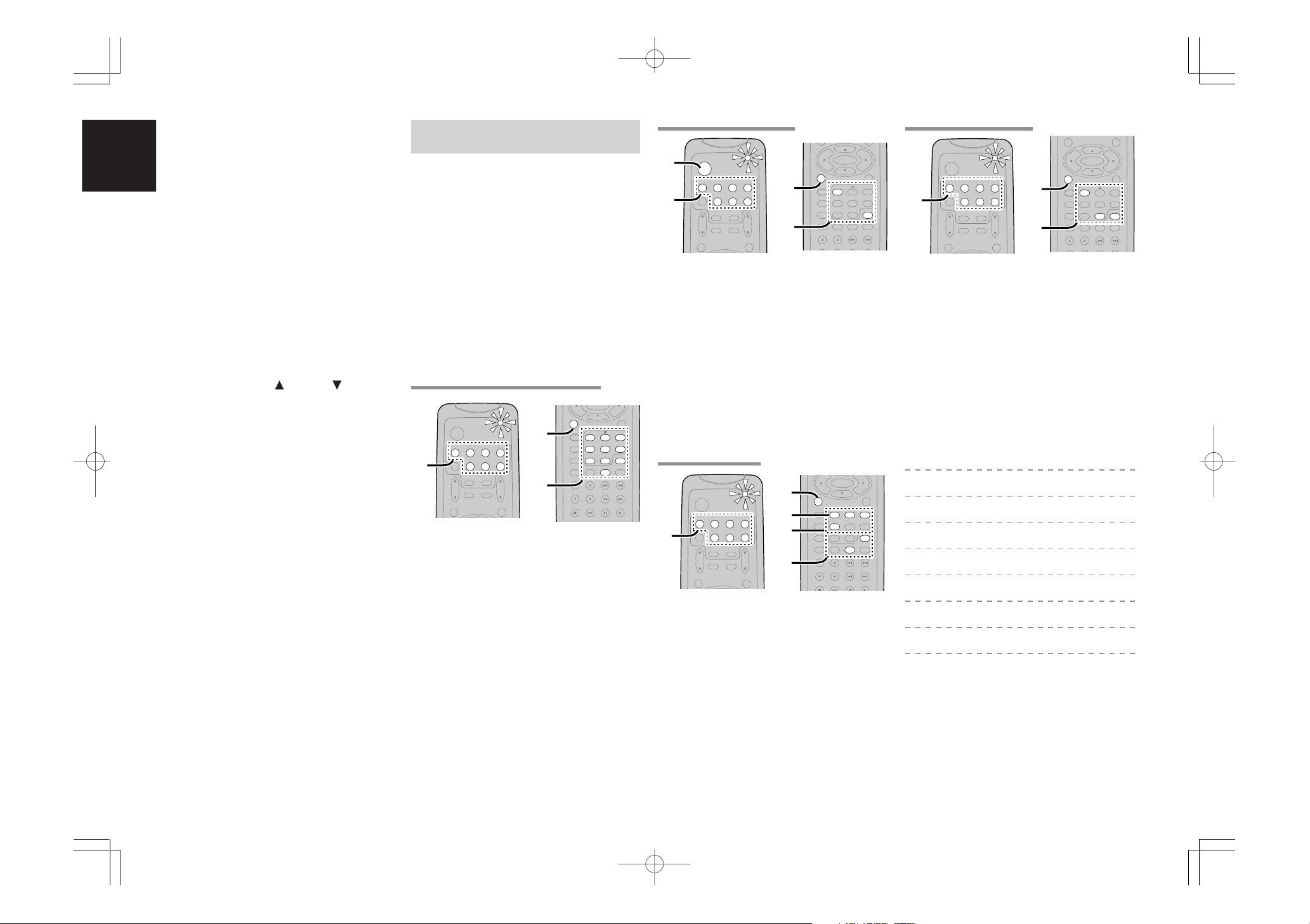
PROGRAMMING WITH THE 4-DIGIT CODE
SCANNING THE CODE TABLE
1.
Switch on the appliance which should be
controlled.
2.
Press and hold down the Function Selector
button for appliance which should be
controlled and press SETUP button until the
indicator blinking twice.
3.
Press the code 9 - 9 - 1.
The indicator will blink twice.
4.
Aim the remote control at the appliance and
slowly alternate between pressing POWER
button and the
Function Selector
the appliance.
5.
Stop when the appliance turns off.
6.
Press SETUP button once to lock in the code.
CHECKING THE CODE
button for
RESETTING THE ALL CODE
1.
Press and hold down the any Function
Selector button and press SETUP button until
the indicator blinking twice.
2.
Press the code 9 - 8 - 1.
The indicator will blink twice.
Then, RC5500SR will return to the factory
preset code.
Note:
• After this procedure, the selected function button
is set initial code and other function buttons are
set initial code too.
Once you have found and the codes for your various
appliances, you may want to write them down here.
TV
VCR
DSS
1.
Press and hold down the Function Selector
button for the appliance which should be
controlled and press SETUP button until the
indicator blinks twice.
2.
Press the 4-digit code for appliance (code
table at the end of this book)
3.
When the procedure is successful, the indicator
will blink twice.
Note:
• If the indicator did not blink twice, then repeat
steps 1 through 2 and try entering the same code
again.
1.
Press and hold down the Function Selector
button for appliance which should be
controlled and press SETUP button until the
indicator blinking twice.
2.
Press the code 9 - 9 - 0.
The indicator will blink twice.
3.
To view the code for first digit, press 1 once.
DVD
CD
TAPE
CDR
MD
Wait 3 seconds, count the indicator blinks
(e.g. 3 blinks = 3) and write down the number.
Note:
• If a code digit is “0”, the indicator will not blink.
4.
Repeat step 3 three more times for remaining
digits. Use 2 for the second digit, 3 for the
third digit, and 4 for the fourth digit.
8
SR5500UDFU01ENG12 04.8.2, 4:12 PMPage 8 AdobePageMaker6.5J/PPC
S
U
R
R
O
U
N
D
A
V
S
U
R
R
O
U
N
D
R
E
C
E
IV
E
R
S
R
5
5
0
0
D
O
W
N
UP
V
O
L
U
M
E
IN
PUT
S
EL
ECT
O
R
P
O
W
E
R
O
N
/
O
F
F
P
H
O
N
E
S
STAN
D
BY
M
UT
E
M
U
L
TI
M.
SP
EAK
ER
B
PU
RE
S
E
TU
P
D
IR
E
C
T
SI
M
P
LE
A
UTO
HT
-E
Q
M
ENU
E
N
TE
R
D
IS
P
L
A
Y
ME
MO
R
Y
C
LE
A
R
T
M
O
D
E
E
X
IT
BAN
D
M
O
DE
A
U
X
1
IN
P
U
T
A
U
D
I
O
S
VI
D
E
O
V
ID
E
O
L
R
7
.1
C
H
IN
P
U
T
CH.SEL LIP.SYNC
PTY
SUB-T/ATT
AUDIO
INPUT/DISC+
F.DIRECT
RDS
TUNE/SEARCH
T-MODE
TREBLE
CHANNEL/SKIP
BASS
A/D
P.SCAN/V-OFF
7.1CH IN
STEREO
MCH-ST
MEMO
CLEAR
DISPLAY
NIGHT
CSII EX/ES VIRTUAL
DTS
PURE DIRECT
AUTO
321
654
9807
T.TONE
MENU OFF
SET UP/
MENU
OSD
VOL.
TV
SLEEP
MUTE
AMP
TUNERCDTAPE
CDR/MD
DVD
POWER
VCR1
DSS/VCR2
TV
SYSTEM REMOTE CONTROLLER
RC5500SR
VOL.
MAIN
ENTER
AUX1
ENTER
CH.SEL LIP.SYNC
PTY
SUB-T/ATT
AUDIO
INPUT/DISC+
F.DIRECT
RDS
TUNE/SEARCH
T-MODE
TREBLE
CHANNEL/SKIP
BASS
A/D
P.SCAN/V-OFF
7.1CH IN
STEREO
MCH-ST
MEMO
CLEAR
DISPLAY
NIGHT
CSII EX/ES VIRTUAL
DTS
PURE DIRECT
AUTO
321
654
9807
T.TONE
MENU OFF
SET UP/
MENU
OSD
VOL.
TV
VOL.
MAIN
SLEEP
MUTE
AMP
TUNERCDTAPE
CDR/MD
DVD
POWER
VCR1
DSS/VCR2
TV
SYSTEM REMOTE CONTROLLER
RC5500SR
AUX1
3.
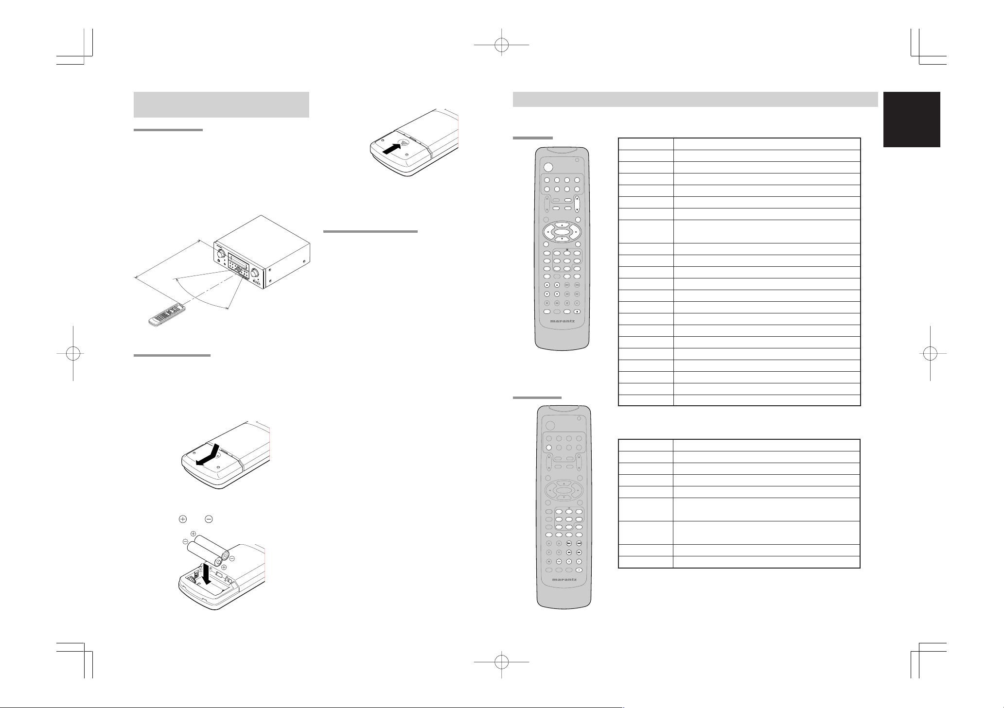
OPERATION OF REMOTE CONTROL
UNIT
REMOTE CONTROL
The distance between the transmitter of the
remote control and the IR SENSOR of the SR5500
should be less than 5 meters. If the remote control
is pointed in a direction other than the IR SENSOR
or if there is an obstacle between them, use of the
remote control may not be possible.
Remote-controllable range
SR5500
Close the cover until it clicks.
Notes:
• Do not mix alkaline and manganese batteries.
• Do not mix old and new batteries.
CAUTIONS ON BATTERIES
GENERAL INFORMATION OF RC5500SR TO SR5500
To control the SR5500 by your RC5500SR, you have to select the device AMP or TUNER by pressing the
function selector button. Please refer below for the details in AMP and TUNER mode.
AMP MODE
POWER Turns the SR5500 on and off
Function selector *
SLEEP * Sets the sleep timer function
MUTE * Decreases the sound temporarily
VOL 34 * Adjusts the over all sound level
MENU Enters the SETUP MENU
Cursor Moves the cursor for settings in the SETUP MENU
ENTER • Enters the SETUP MENU
• Use “AAA” type batteries in this remote control
SETUP/T.TONE Enters the test tone mode for setting the Speaker Level Setup
MENU OFF Exits from the SETUP MENU
PURE DIRECT * Selects the Pure Direct mode
NIGHT * Turns on or off the NIGHT mode
DISPLAY * Change the front display mode
Surround mode (1-8)
7.1CH-IN (9) Selects the 7.1CH IN
A/D (0) Switches between the analog and digital inputs
BASS 34 * Adjusts the tone control of low frequency sound
TREBLE 34 * Adjusts the tone control of high frequency sound
SUB-T/ATT Reduces the input level
P.SCAN/V-OFF Turns on or off the Video output
CH. SEL Adjusts the 7.1 ch input level
LIP.SYNC Selects the LIP. SYNC mode
* These buttons are used to control SR5500 in any function mode.
Approx. 5 m
60°
Remote control unit (RC5500SR)
LOADING BATTERIES
The life of the batteries used with the remote
control is about 4 months with normal use. Also be
sure to replace batteries earlier when you notice
that they are getting weak.
1.
Remove the back cover.
unit.
• If the remote control unit does not operate from
close to the main unit, replace the batteries with
new ones, even if less then a year has passed.
• The included battery is only for verifying
operation. Replace it with a new battery as soon
as possible.
• When inserting the batteries, be careful to do so
in the proper direction, following the + and marks in the remote control unit’s battery
compartment.
• To prevent damage or battery fluid leakage:
- Do not use a new battery with an old one.
- Do not use two different types of batteries.
- Do not short-circuit, disassemble, heat or
dispose of batteries in flames.
• Remove the batteries when not planning to use
the remote control unit for a long period of time.
TUNER MODE
• If the batteries should leak, carefully wipe off the
fluid from the inside of the battery compartment,
then insert new batteries.
• When disposing of used batteries, please
comply with governmental regulations or
environmental public instruction’s rules that
apply in your country or area.
TUNER Selects a frequency band
0-9 Inputs the numeric #s
CLEAR Clears the inputting
MEMO Enters the tuner preset memory numbers
P.SCAN/V-OFF Starts preset scan
2.
Insert the new batteries (AAA type) with
correct and polarity.
CHANNEL/SKIP • Selects a preset station
4
/
¢
TUNE/SEARCH Tunes a station
5
/
6
T-MODE
F.DIRECT
SR5500UDFU01ENG12 04.8.2, 4:12 PMPage 9 AdobePageMaker6.5J/PPC
Selects a particular source component
• Confirms the settings in SETUP MENU
Selects the surround mode
1 2
Selects the auto stereo mode or mono mode
2
Selects the “Frequency direct input”
ENGLISH
9
ENGLISH
CH.SEL LIP.SYNC
PTY
SUB-T/ATT
AUDIO
INPUT/DISC+
F.DIRECT
RDS
TUNE/SEARCH
T-MODE
TREBLE
CHANNEL/SKIP
BASS
A/D
P.SCAN/V-OFF
7.1CH IN
STEREO
MCH-ST
MEMO
CLEAR
DISPLAY
NIGHT
CSII EX/ES VIRTUAL
DTS
PURE DIRECT
AUTO
321
654
9807
T.TONE
MENU OFF
SET UP/
MENU
OSD
VOL.
TV
VOL.
MAIN
SLEEP
MUTE
AMP
TUNERCDTAPE
CDR/MD
DVD
POWER
VCR1
DSS/VCR2
TV
SYSTEM REMOTE CONTROLLER
RC5500SR
ENTER
AUX1
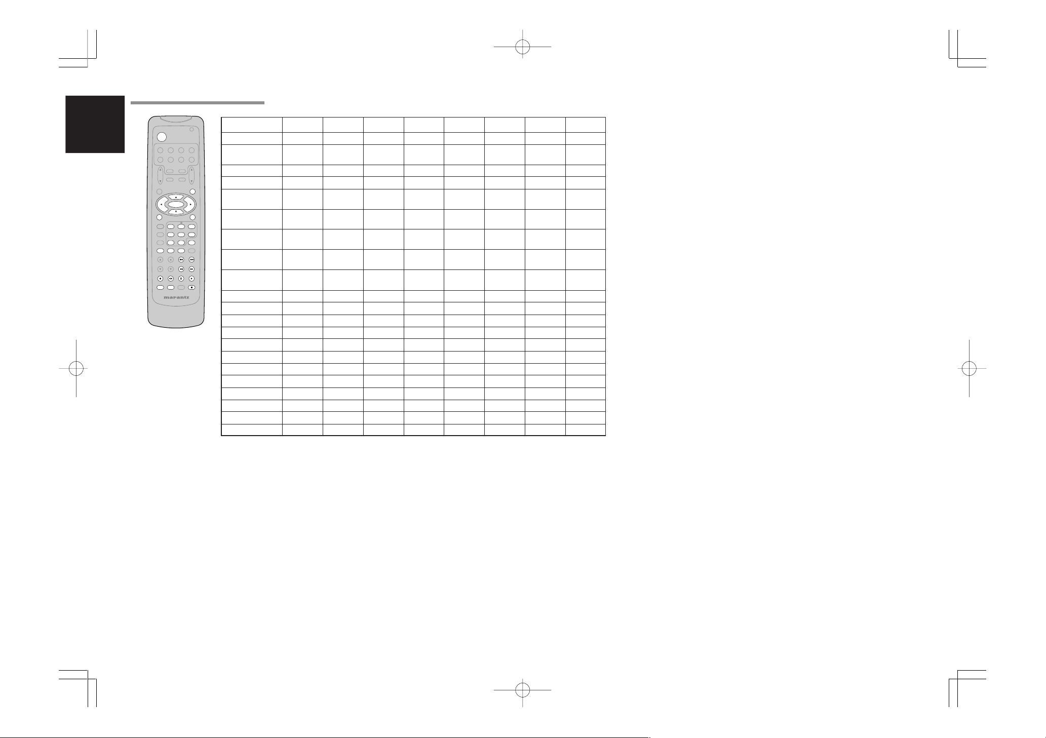
THE CONTRABLE FUNCTION TABLE
POWER POWER POWER POWER POWER POWER POWER POWER POWER
MENU
Cursor Cursor Cursor Cursor Cursor ––––
ENTER OK OK OK OK ––––
SETUP/T.TONE ––
MENU OFF –
0 - 9
CLEAR
MEMO ––
CHANNEL/SKIP 4CH– PREV PREV CH– PREV PREV PREV PREV
CHANNEL/SKIP ¢CH+ NEXT NEXT CH+ NEXT NEXT NEXT NEXT
TUNE/SEARCH 5– REWIND REWIND – REWIND REWIND REWIND REWIND
TUNE/SEARCH 6– FF FF – FF FF FF FF
0
(REC) – REC –––REC REC REC
T-MODE
RDS
;
F.DIRECT
INPUT/DISC+ INPUT SEL. TV/VCR DISC+ TV/DSS DISC+ – DISC+ –
AUDIO – AUDIO AUDIO AUDIO ––––
PTY
9
SUB-T/ATT ––SUBTITLE –––––
1 2
2
TV VCR DVD DSS CD TAPE CDR MD
CALL UP CALL UP CALL UP CALL UP SWITCH SWITCH SWITCH SWITCH
MENU MENU MENU MENU DISPLAY DISPLAY DISPLAY DISPLAY
SETUP
MENU
CANCEL
MENU MENU
–
–––––
CANCEL
––––
INPUT INPUT INPUT INPUT INPUT INPUT INPUT INPUT
NUMERIC NUMERIC NUMERIC NUMERIC NUMERIC NUMERIC NUMERIC NUMERIC
INPUT TAPE INPUT INPUT INPUT INPUT INPUT INPUT
CLEAR SPEED CLEAR CLEAR CLEAR CLEAR CLEAR CLEAR
CALL
PROGRAM PROGRAM PROGRAM PROGRAM PROGRAM
–
CALL CALL CALL CALL
–––––DIRECTION ––
– PAUSE PAUSE – PAUSE PAUSE PAUSE PAUSE
– PLAY PLAY – PLAY PLAY PLAY PLAY
– STOP STOP – STOP STOP STOP STOP
10
SR5500UDFU01ENG12 04.8.2, 4:12 PMPage 10 AdobePageMaker6.5J/PPC
 Loading...