

Page 1

RS-232C Control Specification :
Rev 00
SR5001
RS-232C Control Specification
Category :
Document Version :
A/V Receiver
1.0
Author(s) :
Date : 2006/08/18
Number of Page : 20
Marantz America, Inc.
Marantz America, Inc. 2006
All rights are reserved. Reproduction in whole or in part is prohibited without the written consent of copyright.
All specifications might be subject to change without notice.
Page 2

SR5001 RS-232C Control Specification Page: 2 / 20
Document Version [1.0]
Table of Contents
Introduction............................................................................................................................................................ 3
1.
1-1. Purpose ............................................................................................................................................................ 3
1-2. Scope................................................................................................................................................................ 3
1-3. Abbreviations ...................................................................................................................................................3
1-4. References....................................................................................................................................................... 3
2. Global Description ................................................................................................................................................ 3
2-1. Overview...........................................................................................................................................................3
2-2. Block Diagram.................................................................................................................................................. 3
2-3. Interface connection specification of the product...........................................................................................3
2-4. Assumptions and Dependencies.................................................................................................................... 3
3. Detailed Description.............................................................................................................................................. 4
3-1. Connection format ...........................................................................................................................................4
3-1-1. Physical connection................................................................................................................................. 4
3-1-1-1. Data transmission sequence from Host to Slave ..........................................................................4
3-1-1-2. Data transmission sequence from Slave to Host ..........................................................................4
3-2. Transmission data format................................................................................................................................ 5
3-2-1. Transmission data format from Host to Slave........................................................................................ 5
3-2-1-1. Form1: Command ........................................................................................................................... 5
3-2-1-2. Form2: Status request ..................................................................................................................... 5
3-2-2. Transmission data format from Slave to Host........................................................................................5
3-2-2-1. Form1: ACK/NAK ............................................................................................................................ 5
3-2-2-2. Form2: Status answer and Auto status feedback.......................................................................... 5
3-3. The transaction sequences and the regulations............................................................................................ 6
3-3-1. The transaction sequences..................................................................................................................... 6
3-3-2. The transaction regulations..................................................................................................................... 6
3-3-3. Specification of Auto status feedback ..................................................................................................... 6
3-3-4. Example of the transactions.................................................................................................................... 6
3-3-5. Examples of the handshaking flowchart ................................................................................................7
3-3-5-1. Example of successful handshaking.............................................................................................. 7
3-3-5-2. Examples of handshaking error...................................................................................................... 7
4. Recommendations of Command, Status and Layer definition..................................................................... 8
5. Definitions of Command, Status and Layer......................................................................................................9
5-1. Normal Command list...................................................................................................................................... 9
5-1-1. Main function contents............................................................................................................................. 9
5-1-2. Display and Menu contents...................................................................................................................10
5-1-3. Surround contents ................................................................................................................................. 11
5-1-4. Tuner contents ....................................................................................................................................... 13
5-1-5. XM Contents ..........................................................................................................................................13
5-1-6. Multi Room contents.............................................................................................................................. 14
5-2. Specific Commands....................................................................................................................................... 15
5-3. Status request and Status answer list...........................................................................................................16
5-3-1. Normal Status request and Status (answer and feedback) list........................................................... 16
5-3-2. Layer of the statuses .............................................................................................................................19
6. Revision history...................................................................................................................................................20
Company Restricted
Page 3
SR5001 RS-232C Control Specification Page: 3 / 20
Document Version [1.0]
1. Introduction
1-1. Purpose
This document was written as a reference specification of products that are controled by the host
controller.
1-2. Scope
This document would be using by software or hardware engineers for production of the product.
1-3. Abbreviations
Abbreviation Description
1-4. References
- Hardware Software Interface Specification ver. 1.02 / author: N.Sakamoto
-
2. Global Description
2-1. Overview
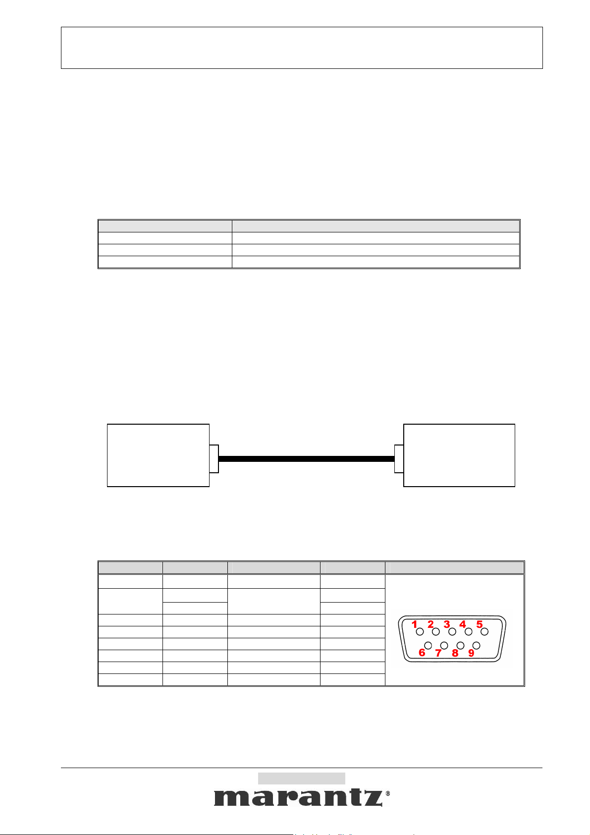
A Host controller can control or watch out the product as a Slave very easily via the communication cable.
2-2. Block Diagram
* The product connector is using D-SUB 9pin male.
* RS232C cable must use D-SUB 9pin female to connect the products.
2-3. Interface connection specification of the product
uP Interface Signal name Connection device D-Sub Pin Connecter
2-4. Assumptions and Dependencies
HOST
(Controller)
- N.C. - 1
TxD (output) 2 UART
RxD (input)
- N.C. - 4
- GND GND 5
- N.C. - 6
- N.C. - 7
- N.C. - 8
- N.C. - 9
RS232C cable (straight)
RS232C
Level shift driver
3
SLAVE
(The product)
Connector
D-SUB (9pin, male)
<The product connector>
RS232C D-SUB (9pin,Male)
Company Restricted
Page 4
SR5001 RS-232C Control Specification Page: 4 / 20
Document Version [1.0]
3. Detailed Description
The interface specification between the product and a Host controller is described below.
3-1. Connection format
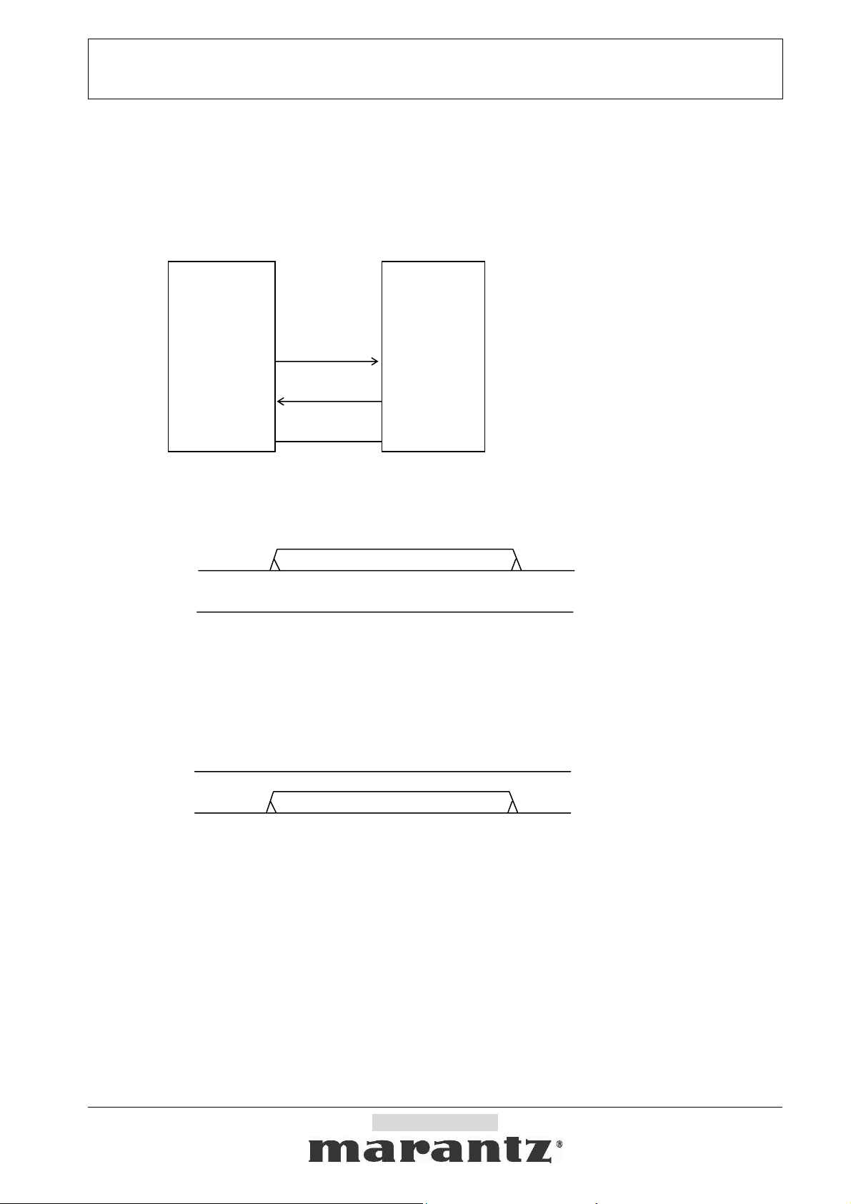
3-1-1. Physical connection
Host (Controller) Slave (the product)
Serial setting <RS232C basic
Baud Rate : 9600bps
TxD
Data Bits : 8bit
Parity : None
RxD
Stop bit : 1bit
Handshaking : None
3-1-1-1. Data transmission sequence from Host to Slave
Host (Controller) Slave (The product)
3-1-1-2. Data transmission sequence from Slave to Host
GND
TxD → RxD
RxD ← TxD
1. Host starts a data transmission from TxD.
2. Host performs the data transmission of the number of required bytes, and ends a transmission.
Host (Controller) Slave (The product)
TxD → RxD
RxD ← TxD
1. Slave starts a data transmission from TxD.
2. Slave performs the data transmission of the number of required bytes, and ends a transmission.
RxD
TxD
GND
Company Restricted
Page 5

SR5001 RS-232C Control Specification Page: 5 / 20
C
K
Document Version [1.0]
3-2. Transmission data format
3-2-1. Transmission data format from Host to Slave
There are two kinds of transmission data form from Host shown below.
3-2-1-1. Form1: Command
Command is a data that requests some status change.
Start character : ’@’
COMMAND : see “Command list”
End character (CR) : 0Dh
start
‘@’
3-2-1-2. Form2: Status request
Status request is a data that requests a answer of some status.
Start character : ’@’
Request status : see “Status request list”
Request character : ‘?’
End character (CR) : 0Dh
start
‘@’
3-2-2. Transmission data format from Slave to Host
There are two kinds of transmission data form from Slave shown below.
3-2-2-1. Form1: ACK/NAK
ACK is a reply data from Slave when Slave got an acceptable command data from Host.
(ACK is sent to Host when Slave has no related status by the Command.)
Start character : ’@’, ACK : 06h, End character (CR) : 0Dh
‘
@
NAK is a reply data from Slave when Slave got an incorrect Command data, Status request data or
some other data from Host.
Start character : ’@’, NAK : 15h, End character (CR) : 0Dh
3-2-2-2. Form2: Status answer and Auto status feedback
Status answers are reply data when Slave got an acceptable Request status or Command data from
Host. Auto status feedbacks are send to Host data when a Slave’s status is changed.
Start character : ’@’
Answer character : see “Status list”
End character (CR) : 0Dh
start
‘@’
command
“xxx:”+”...”
request status
“xxx:?”+”...”
A
r
06h
’
NAK
r
15h
‘
@
’
status
“xxx:”+”...”
end
0Dh
end
0Dh
CR
0Dh
CR
0Dh
end
0Dh
Company Restricted
Page 6
SR5001 RS-232C Control Specification Page: 6 / 20
Document Version [1.0]
3-3. The transaction sequences and the regulations
3-3-1. The transaction sequences
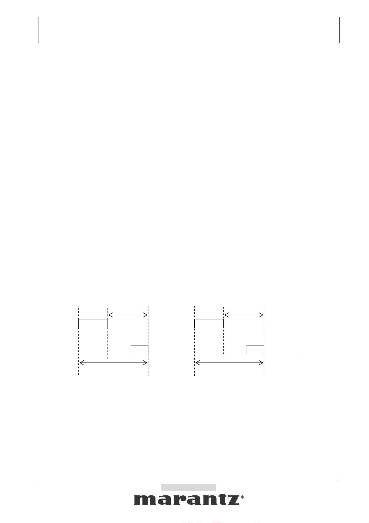
The transactions have three kinds of sequence.
*A transaction is a Command from Host then Slave will be an answer by Status answer, ACK or NAK.
*A transaction is a Status request from Host then Slave will be an answer by Status answer or NAK.
*A transaction is Auto status feedback from Slave when a Slave’s status changed. (If the auto status
feedback is enabled.)
3-3-2. The transaction regulations
The transactions have some kinds of regulation.
* An answer (ACK, NAK or Status answer) transmittion by Slave has to finish within 500ms when got a
Command or a Status request from Host.
* Host must not transmit an another Command or Status request until "it receives a answer by a
previous Command or Status request" or "it passes a term of waitinng time from a finishing of previous
transmission of a Command or a Status request ".
* Slave has to finish a transaction under 500ms when it sends Auto status feedback data.
3-3-3. Specification of Auto status feedback
There are some specific regulations about Auto status feedback.
* The product status has segmented into four layers of 1, 2, 3 and 4.
* The status of layer 1 are assigned most kindly status to Host. (The statuses of layer 2 are assigned
kindly status, the statuses of layer 3 are not so need status to Host and the statuses of layer 4 are
probably no wished statuses.)
* Each layer status can control transmit enable or disable by Host command. (The product default
would be all disables.)
* Slave sends auto status feedback by itself when the status is changed and if the status feedback is
enabled.
* The product defined and segmentationed layers are takeing in status list.
3-3-4. Example of the transactions
<Host> <Slave>
TxD RxD
RxD TxD
Command
max. 0.5sec
Status answer ,
ACK or NAK
a transaction a transaction
Example of the transactions
Company Restricted
Status
request
max. 0.5sec
Status answer
Page 7
SR5001 RS-232C Control Specification Page: 7 / 20
p
p
A
A
Document Version [1.0]
3-3-5. Examples of the handshaking flowchart
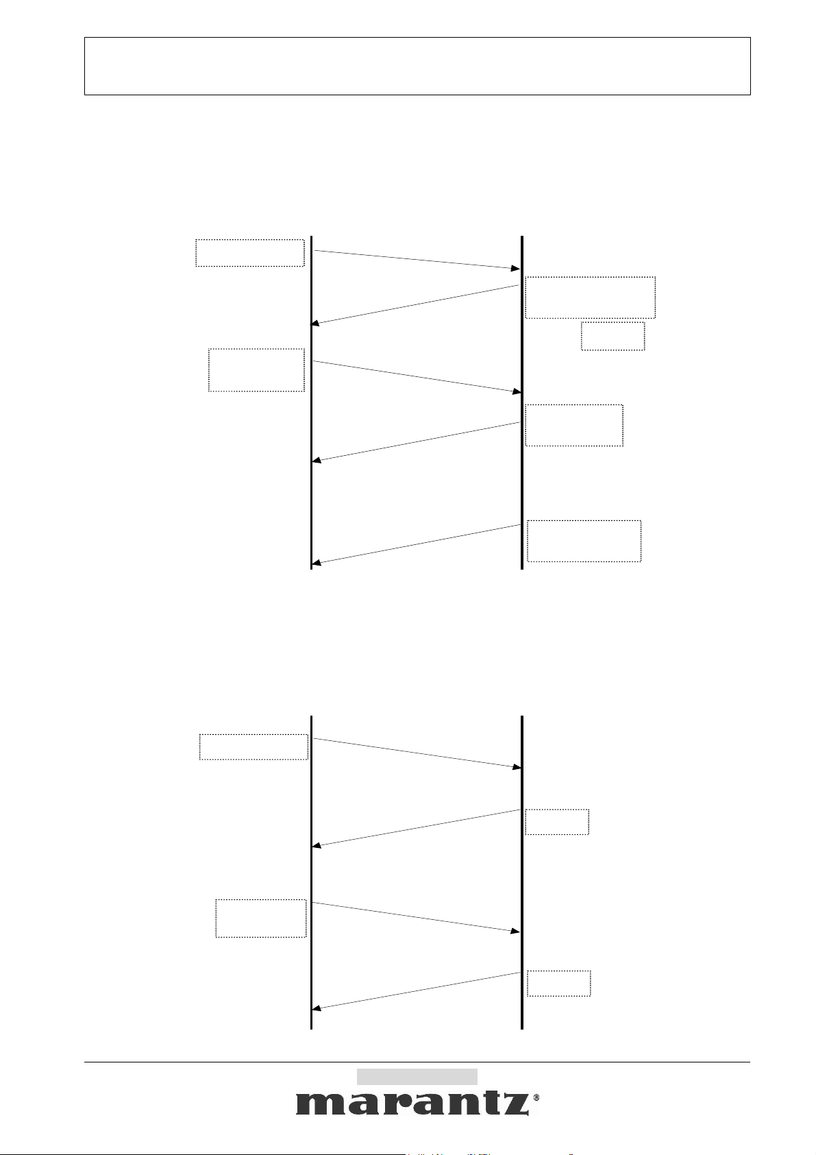
3-3-5-1. Example of successful handshaking
SLAVEHOST
Com m and
Status
request
Com m and
acce
Request
acce
Changed
som e status!
table
Related
Status answer
or
Status
answer
uto status
feedback
CK
table
The product can reply ACK instead of related status, if the product can not send the related status
immediatly.
3-3-5-2. Examples of handshaking error
SLAVEHOST
Com m and
Com m and
in c o rre c t
NAK
Status
request
Request
in c o rre c t
NAK
Company Restricted
Page 8

SR5001 RS-232C Control Specification Page: 8 / 20
Document Version [1.0]
4. Recommendations of Command, Status and Layer definition
- All Commands, Statuses and Layers will be defined other specific document.
- [MANDATORY] The product MUST have Commands and the Statuses same as a remote controller
buttons (IR controller) of the product.
- All Commands are required working by discreate as ON/OFF commands. (It means that do not support
TOGGLE command only. )
- All Commands and Statuses are defined same chharacter size except ACK/NAK on the product.
( Recommended character length : 3~6 characters )
-
It permits attaching 0x0A character to a reply characters from the product. In this case, must suppose that the object
is followed altogether.
- Recommend to supports numbers or values direct setting command, if it has variable numbers or
values.
Company Restricted
Page 9
SR5001 RS-232C Control Specification Page: 9 / 20
Document Version [1.0]
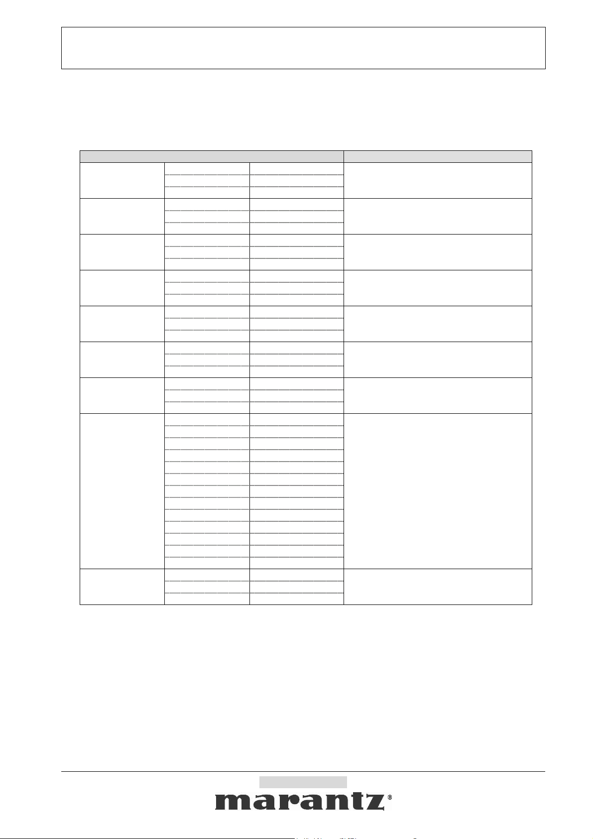
5. Definitions of Command, Status and Layer
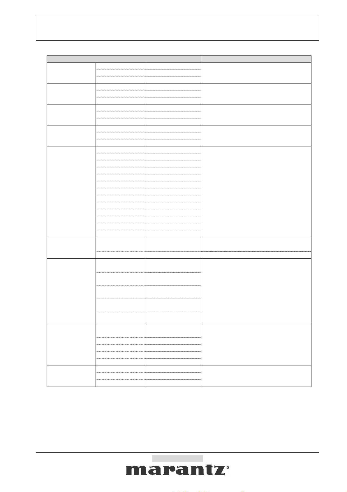
This section is told how to define “Command”, “Status” and “Layer” of this product.
5-1. Normal Command list
5-1-1. Main function contents
Command Reply from Slave
POWER
AUDIO ATT
AUDIO MUTE
VIDEO MUTE
VOLUME
TONE BASS
TONE TREBLE
SOURCE Select
7.1 Channel Input
TOGGLE “PWR:0”
OFF “PWR:1”
ON “PWR:2”
TOGGLE “ATT:0”
OFF “ATT:1”
ON “ATT:2”
TOGGLE “AMT:0”
OFF “AMT:1”
ON “AMT:2”
TOGGLE “VMT:0”
OFF “VMT:1”
ON “VMT:2”
VALUE “VOL:0xxx”
UP “VOL:1”
DOWN “VOL:2”
VALUE “TOB:0xxx”
UP “TOB:1”
DOWN “TOB:2”
VALUE “TOT:0xxx”
UP “TOT:1”
DOWN “TOT:2”
TV “SRC:1”
DVD “SRC:2”
VCR1 “SRC:3”
DSS/VCR2
AUX1 “SRC:9”
AUX2 “SRC:A”
CD “SRC:C”
CD-R “SRC:D”
TAPE “SRC:E”
TUNER “SRC:F”
FM “SRC:G”
AM “SRC:H”
XM “SRC:J”
TOGGLE “71C:0”
OFF “71C:1”
ON “71C:2”
“SRC:5”
xxx = Vol. value as +18 ~ -99,
0db = ”VOL: 00”, -∞ = “VOL:-ZZ”
xxx = vol. value as +6 ~-6
xxx = vol. value as +6 ~-6
“SRC:va”, (v ,a= ‘0’ – ‘I’)
“PWR:1”
“PWR:2”
“ATT:0”(None)
“ATT:1”(OFF)
“ATT:2”(ON)
“AMT:1”
“AMT:2”
“VMT:1”
“VMT:2”
“VOL:xxx”
“TOB:xxx”
“TOT:xxx”
(v = video, a = audio.)
v = 0 (V-OFF)
a = N (7.1CH)
“71C:1” (OFF)
“71C:2” (ON)
Company Restricted
Page 10
SR5001 RS-232C Control Specification Page: 10 / 20
Document Version [1.0]
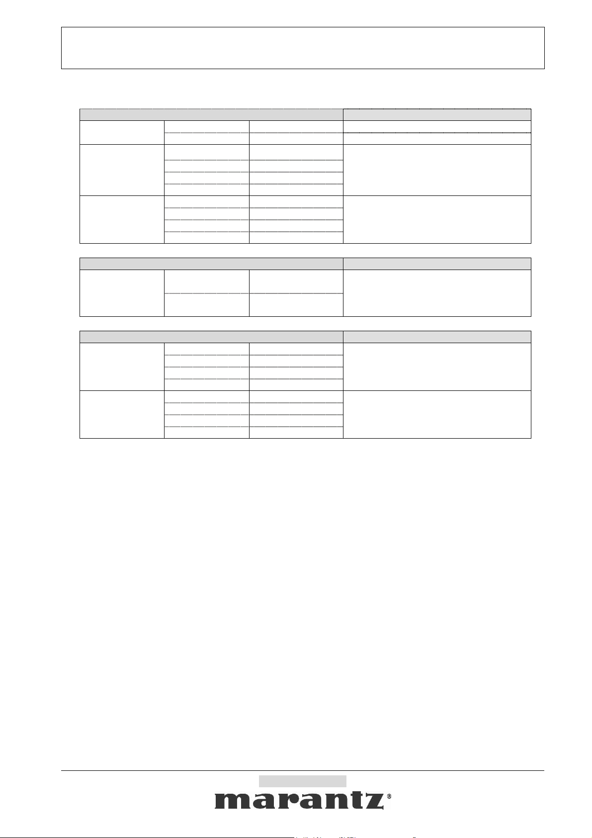
5-1-2. Display and Menu contents
Command Reply from Slave
SLEEP
VALUE “SLP:0xx” “SPL:xx”
OFF “SLP:1” “SPL:00”
TOGGLE “MNU:0”
MENU
OFF(EXIT) “MNU:1”
ON “MNU:2”
“MNU:1”(non-Menu mode)
“MNU:2”(on Menu mode)
ENTER “MNU:3”
UP “CUR:1”
CURSOR
DOWN “CUR:2”
LEFT “CUR:3”
ACK
RIGHT “CUR:4”
Command Reply from Slave
TRG. 1 OFF
DC TRG.
TRG. 1 ON
“DCT:11”
(DC TRG. 1 OFF)
“DCT:12”
(DC TRG. 1 ON)
“DCT:a”
( a = 1:OFF, 2:ON), a = TRG.1
Command Reply from Slave
TOGGLE “SSU:0”
Simple Setup
OFF(EXIT) “SSU:1”
ON “SSU:2”
“SSU:1”(non-Setup mode),
“SSU:2”(on Setupmode)
ENTER “SSU:3”
CURSOR
(same as Menu
Cursor )
UP “CUR:1”
DOWN “CUR:2”
LEFT “CUR:3”
RIGHT “CUR:4”
ACK
Company Restricted
Page 11

SR5001 RS-232C Control Specification Page: 11 / 20
Document Version [1.0]
5-1-3. Surround contents
Command Reply from Slave
AUTO “SUR:00”
STEREO “SUR:01”
DOLBY “SUR:02”
PL2xMOVIE “SUR:03”
PL2 MOVIE “SUR:04”
PL2xMUSIC “SUR:05”
PL2 MUSIC “SUR:06”
PL2xGAME “SUR:07”
PL2 GAME “SUR:08”
Dolby
PROLOGIC
“SUR:09”
EX/ES “SUR:0A”
VIRTUAL 6.1 “SUR:0B”
DTS ES “SUR:0E”
Surr. Mode
NEO6 CINEMA “SUR:0F”
NEO6 MUSIC “SUR:0G”
Multi Ch.
STEREO
“SUR:0H”
“SUR:x“
(x = ‘0’ ~’Z’)
CS CINEMA “SUR:0I”
CS MUSIC “SUR:0J”
CS MONO “SUR:0K”
VIRTUAL “SUR:0L”
DTS “SUR:0M”
DD+ PL2x MOVIE “SUR:0O”
DD+ PL2x MUSIC “SUR:0P”
SOURCE
DIRECT
“SUR:0T”
PURE DIRECT “SUR:0U”
UP “SUR:1”
DOWN “SUR:2”
Company Restricted
Page 12
SR5001 RS-232C Control Specification Page: 12 / 20
Document Version [1.0]
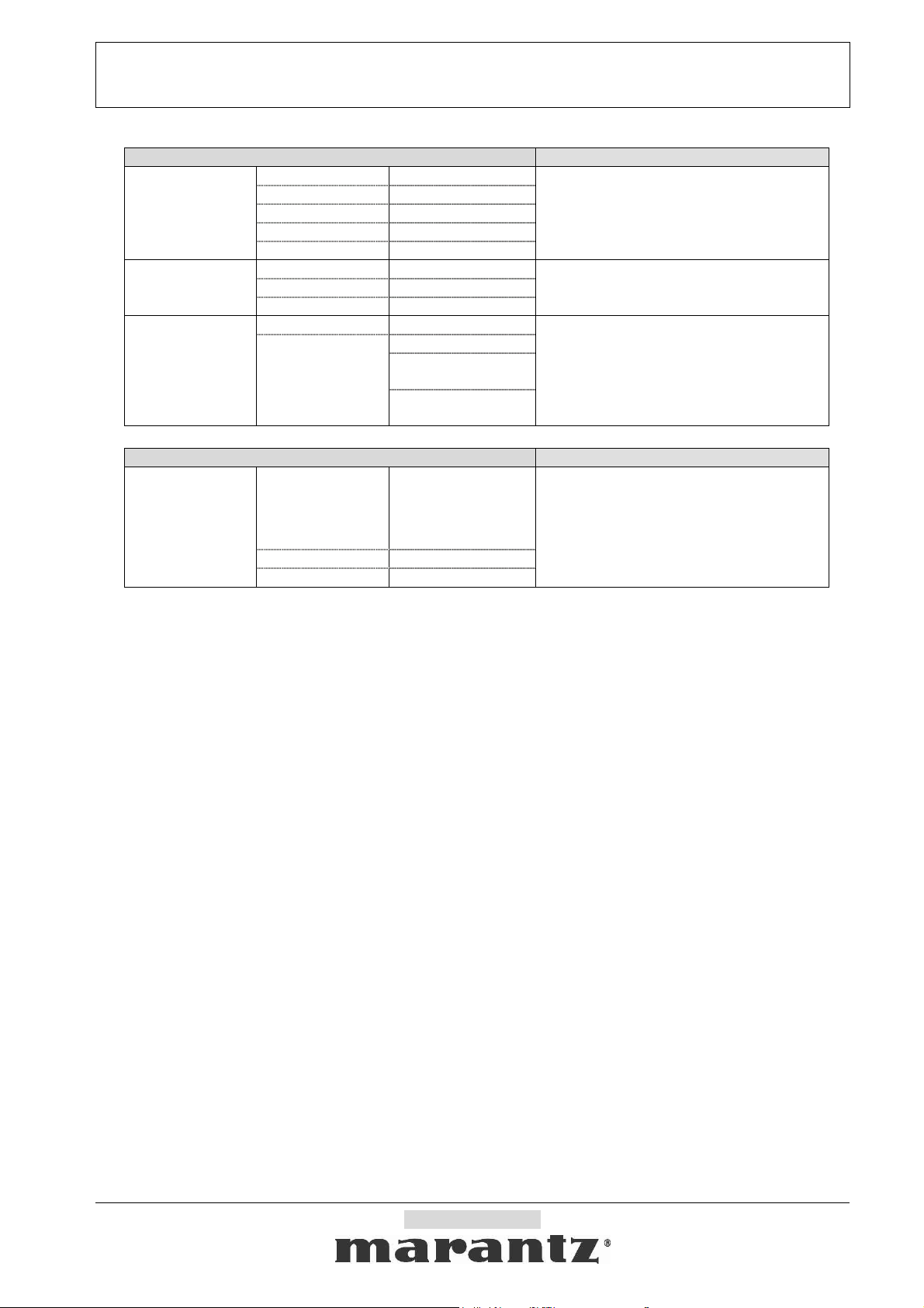
Command Reply from Slave
Tes t Ton e
(Force start/stop
Tes t Ton e wi t h
Auto mode)
Night Mode
TOGGLE “TTO:0”
OFF “TTO:1”
ON “TTO:2”
“TTO:2xy” (ON, x= auto(0)/manual(1), y=
NEXT “TTO:3”
PREV “TTO:4”
TOGGLE “NGT:0”
OFF “NGT:1”
ON “NGT:2”
“TTO:1xy” (OFF),
ch.)
“NGT:1”(OFF),
“NGT:2”(ON)
BYPASS “DHM:0”
“DHM:1”
Dolby Headphone
Mode
DH1
(+PL2 MOVIE)
“DHM:2”
x = Dolby Headphone mode
“DHM:x”
(+PL2 MUSIC)
“DHM:3”
Command Reply from Slave
“LIP:0xxx“
Lip Sync.
VAL U E
UP “LIP:1”
xxx = 000 (OFF),
xxx = 010,020,...190,200
(ms)
xxx = 010,020,...190.200 ms
(xxx = value)
“LIP:xxx”
(xxx = Lip Sync. value)
xxx = 000 (OFF),
DOWN “LIP:2“
Company Restricted
Page 13
SR5001 RS-232C Control Specification Page: 13 / 20
Document Version [1.0]
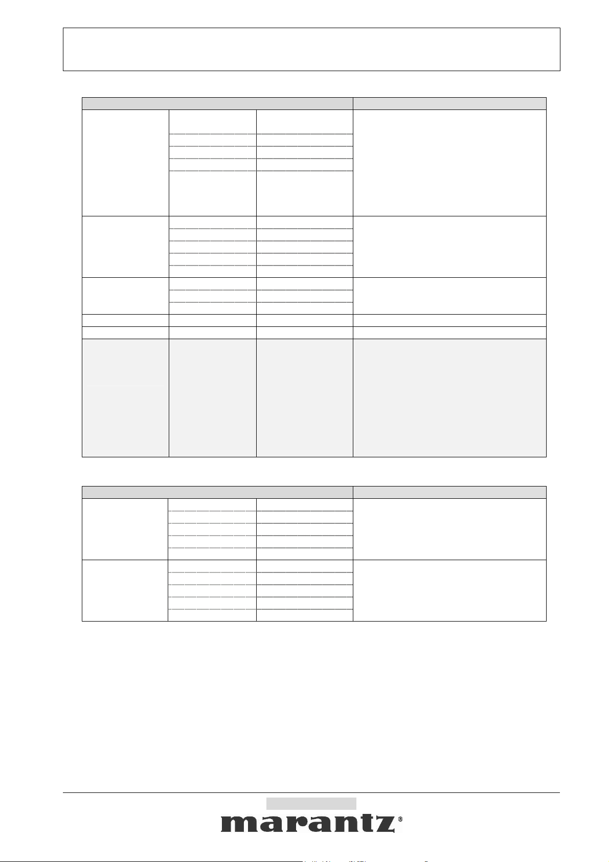
5-1-4. Tuner contents
Command Reply from Slave
Tuner Frequency
VAL UE
UP “TFQ:1“
DOWN “TFQ:2“
“TFQ:0xxxxx“ (xxxx
x = freq.)
if ( xxxxx < 00256 ) band = XM;
else if (xxxxx < 02000) band=AM;
Auto-UP “TFQ:3“
“TFQ:xxxxx”
(xxxxx = Frequency)
else band=FM;
(ex.“08750” = FM87.50MHz)
Auto-DOWN “TFQ:4“
*Auto-UP/DOWN dose not operate in
XM
*XM can be selected When Band is XM.
VALUE “TPR:0ww”
Tuner Preset
UP “TPR:1”
DOWN “TPR:2”
P-Scan start “TPR:3”
“TPR:ww”
(ww = current preset nr.)
(ww = 01 ~ ??)
P-Scan stop “TPR:4”
Tuner mode
TOGGLE “TMD:0”
OFF(MONO) “TMD:1”
ON(AUTO) “TMD:2”
“TMD:0”( - ),
“TMD:1” (MONO),
“TMD:2” (AUTO)
Tuner MEMO - “MEM:0” ACK
CLEAR - “CLR:0” ACK
Tuner Numeric
keys
Key0,
Key1,
Key2,
Key3,
Key4,
Key5,
Key6,
Key7,
Key8,
Key9
“NUM:0”
“NUM:1”
“NUM:2”
“NUM:3”
“NUM:4”
“NUM:5”
“NUM:6”
“NUM:7”
“NUM:8”
“NUM:9”
ACK
5-1-5. XM Contents
Command Reply from Slave
XM DispMode
TOGGLE “XDP:0”
NORMAL “XDP:1”
ART/SNG “XDP:2”
CATEGORY “XDP:3”
STATUS “XDP:4”
“XDP:1”(NORMAL)
“XDP:2”(ART/SNG)
“XDP:3”(CATEGORY)
“XDP:4”(STATUS)
VAL U E “CAT:0xx”
XM Category
CH. UP “CAT:1”
CH. DOWN “CAT:2”
CAT. NEXT “CAT:3”
“CAT:yxx”
y= 1(un search), 2(in search)
xx= Category No. 00(none), 01 to 32
CAT. PREV “CAT:4”
Company Restricted
Page 14
SR5001 RS-232C Control Specification Page: 14 / 20
Document Version [1.0]
5-1-6. Multi Room contents
Command Reply from Slave
Multi Room
POWER
Multi Room
AUDIO MUTE
Multi Room
VOLUME
Multi Room
VOLUME SET
TOGGLE “MPW:0”
OFF “MPW:1”
ON “MPW:2”
TOGGLE “MAM:0”
OFF “MAM:1”
ON “MAM:2”
VALUE “MVL:0xxx”
UP “MVL:1”
DOWN “MVL:2”
xxx = vol. value as +90 ~-90
VARIABLE “MVS:1”
FIXED “MVS:2”
“MPW:1”,
“MPW:2”
“MAM:1”,
“MAM:2”
“MVL:xxx”
“MVS:1”,
“MVS:2”
TV “MSC:1”
DVD “MSC:2”
VCR1 “MSC:3”
DSS/VCR2 “MSC:5”
AUX1 “MSC:9”
Multi Room
SOURCE Select
AUX2 “MSC:A”
CD “MSC:C”
CD-R “MSC:D”
“MSC:va”, (v ,a= ‘0’ – ‘I’)
(v = video, a = audio.)
TAPE “MSC:E”
TUNER “MSC:F”
FM “MSC:G”
AM “MSC:H”
XM “MSC:J”
“MSL:0xx”
(“xx” = min)
“MTF:0xxxxx“
(xxxxx = freq.)
“MSL:xx” (xx = min) Multi Room
“MTF:xxxxx”
(xxxxx = Frequency)
if ( xxxxx < 00256 ) band = XM;
else if (xxxxx < 02000) band=AM;
else band=FM;
(ex.“08750” = FM87.50MHz)
*Auto-UP/DOWN dose not operate in XM
*XM can be selected When Band is XM.
SLEEP
Multi Room
Tuner
Frequency
VAL UE
OFF “MSL:1” “MSL:00”
VAL UE
UP “MTF:1“
DOWN “MTF:2“
Auto-UP “MTF:3“
Auto-DOWN “MTF:4“
Multi Room
Tuner Preset
Multi Room
Tuner mode
VAL UE
UP “MTP:1”
DOWN “MTP:2”
“MTP:0ww”
(ww = preset nr.)
(ww = current preset nr.)
SCAN Start “MTP:3”
SCAN Stop “MTP:4”
TOGGLE “MTM:0”
OFF(MONO) “MTM:1”
“MTM:1”(MONO),
ON(AUTO) “MTM:2”
Company Restricted
“MTP:ww”
(ww = 01 ~??)
“MTM:0”( - ),
“MTM:2”(AUTO)
Page 15

SR5001 RS-232C Control Specification Page: 15 / 20
Document Version [1.0]
Command Reply from Slave
Multi Room
Speaker
TOGGLE “MSP:0”
OFF “MSP:1”
ON “MSP:2”
“MSP:1”,
“MSP:2”
VALUE “MSV:0xxx”
Multi Room
Speaker
VOLUME
UP “MSV:1”
DOWN “MSV:2”
VARIABLE “MSS:1”
xxx = vol. value as +90 ~-90
“MSV:xxx”
FIXED “MSS:2”
Multi Room
Speaker
AUDIO MUTE
TOGGLE “MSM:0”
OFF “MSM:1”
ON “MSM:2”
“MSM:1”,
“MSM:2”
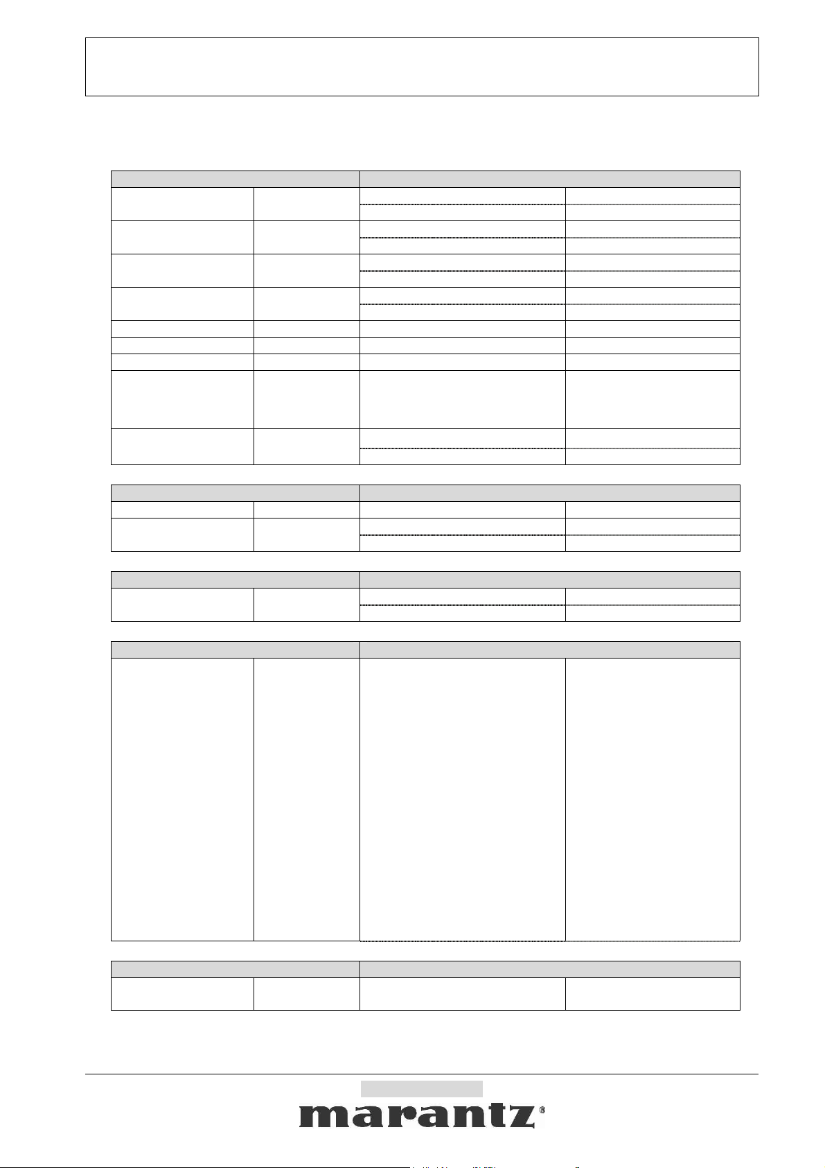
5-2. Specific Commands
Command from Host Reply from Slave
Auto status feedback
(The product default is all
auto status feedback
disabled.)
“AST:x” (x = ‘0’ ~ ’F’)
bit 3 : Layer 4 ( 1 = Enable, 0 = Disable)
bit 2 : Layer 3 ( 1 = Enable, 0 = Disable)
bit 1 : Layer 2 ( 1 = Enable, 0 = Disable)
bit 0 : Layer 1 ( 1 = Enable, 0 = Disable)
same as
command define
Company Restricted
Page 16
SR5001 RS-232C Control Specification Page: 16 / 20
Document Version [1.0]
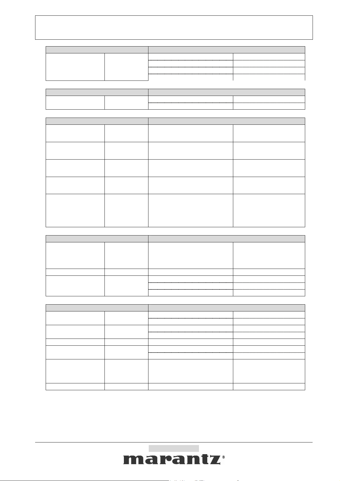
5-3. Status request and Status answer list
5-3-1. Normal Status request and Status (answer and feedback) list
Status request Status answer and feedback
POWER “PWR:?”
AUDIO ATT “ATT:?”
AUDIO MUTE “AMT:?”
VIDEO MUTE “VMT:?”
VOLUME “VOL:?” Volume value = xxx “VOL:xxx”
TONE BASS “TOB:?” Bass value = xxx “TOB:xxx”
TONE TREBLE “TOT:?” Treble value = xxx “TOT:xxx”
SOURCE Select “SRC:?”
Multi Channel “71C:?”
Status request Status answer and feedback
SLEEP “SLP:?” Sleep time (xx = 00 ~ 99) “SLP:xx”
MENU “MNU:?”
Status request Status answer and feedback
Simple Setup “SSU:?”
Status request Status answer and feedback
Digital Signal Format “SIG:?”
OFF “PWR:1”
ON “PWR:2”
OFF “ATT:1”
ON “ATT:2”
OFF “AMT:1”
ON “AMT:2”
OFF “VMT:1”
ON “VMT:2”
Video+Audio source
(v ,a= ‘0’ – ‘F’)
(v = video, a = audio.)
OFF “71C:1”
ON “71C:2”
OFF “MNU:1”
ON “MNU:2”
OFF “SSU:1”
ON “SSU:2”
x =
‘0’ : No detect
’1’ : D DIGITAL AC-3
‘2’ : D DIGITAL SURROUND
‘3’ : D DIGITAL SURR. EX
‘4’ : DTS
‘5’ : DTS ES DISCREATE
‘6’ : DTS ES MATRIX
‘7’ : AAC
‘8’ : MPEG
‘9’ : MLP
‘A’ : PCM
‘B’ : HDCD
‘C’ : DSD
‘D’ : reserved
‘E’ : reserved
‘F’ : OTHER
“SRC:va”
“SIG:x”
x = signal
Status request Status answer and feedback
Lip Sync. “LIP:?”
Lip Sync. : xxx = 000 (OFF)
xxx =010 ~200 (ms)
Company Restricted
“LIP:xxx”
Page 17
SR5001 RS-232C Control Specification Page: 17 / 20
Document Version [1.0]
Status request Status answer and feedback
BYPASS “DHM:0”
DOLBY
HEADPHONE Mode
“DHM:? ”
DH1 “DHM:1”
DH1 + PL2 MOVIE “DHM:2”
DH1 + PL2 MUSIC “DHM:3”
Status request Status answer and feedback
Night Mode “NGT:?”
OFF “NGT:1”
ON “NGT:2”*1
Status request Status answer and feedback
“CHN:********”
XM Ch Name “CHN:?” Channel Name
*=10Byte If data is shorter than
10, Space is padded.
“ARN:********”
XM Artist Name “ARN:?” Artist Name
*=16Byte If data is shorter than
16, Space is padded.
“SON:********”
XM Song Title “SON:?” Song Title
*=16Byte If data is shorter than
16, Space is padded.
“CAT:********”
XM Category Name “CTN:?” Category Name
*=8Byte If data is shorter than 8,
Space is padded.
“SST:*”
0= CHECK ANTENNA
XM Signal Status “SST:?” Antenna Status
1= STRONG
2= MARGINAL
3= WEAK 4= NO
Status request Status answer and feedback
xxxxx = frequency
Tuner Frequency “TFQ:?”
if ( xxxxx < 00256 ) band = XM;
else if (xxxxx < 02000) band=AM;
“TFQ:xxxxx”
else band=FM;
Tuner Preset “TPR:?” xx = preset number (01 ~ ??) “TPR:xx”
- (None) “TMD:0”
Tuner Mode “TMD:?”
OFF (MONO) “TMD:1”
ON (AUTO) “TMD:2”
Status request Status answer and feedback
Multi Room POWER “MPW:?”
AUDIO MUTE
“MAM:?”
OFF “MPW:1”
ON “MPW:2”
OFF “MAM:1” Multi Room
ON “MAM:2”
Multi Room VOLUME “MVL:?” Volume value = xxx “MVL:xxx”
VARIABLE “MVS:1” Multi Room
FIXED “MVS:2”
Video+Audio source
(v ,a= ‘0’ – ‘F’)
“MSC:va”
(v = video, a = audio.)
Volume Set
Multi Room
SOURCE Select
“MVS:?”
“MSC:?”
Multi Room SLEEP “MSL:?” Sleep time min : xx = ‘00’ ~ ‘99’ “MSL:xx”
Company Restricted
Page 18
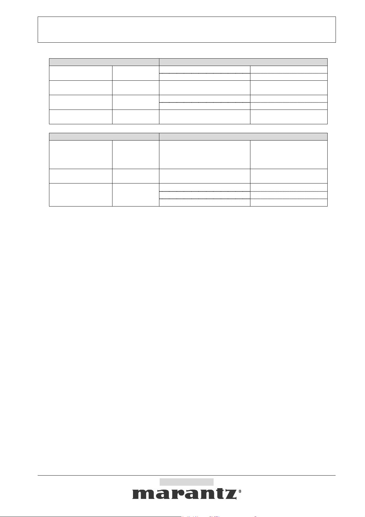
SR5001 RS-232C Control Specification Page: 18 / 20
Document Version [1.0]
Status request Status answer and feedback
OFF “MSP:1” Multi Room
ON “MSP:2”
VARIABLE “MSS:1” Multi Room Speaker
FIXED “MSS:2”
SPEAKER
Multi Room Speaker
VOLUME
Volume Set
Multi Room Speaker
AUDIO MUTE
“MSP:?”
“MSV:?” Volume value = xxx “MSV:xxx”
“MSS:?”
“MSM:?” OFF “MSM:1”
Status request Status answer and feedback
xxxxx = frequency
Multi Room
Tuner Frequency
“MTF:?”
if ( xxxxx < 00256 ) band = XM;
else if (xxxxx < 02000) band=AM;
“MTF:xxxxx”
else band=FM;
Multi Room
Tuner Preset
Multi Room
Tuner Mode
“MTP:?” xx = preset number ( 01 ~ ??) “MTP:xx”
- (None) “MTM:0”
“MTM:?”
OFF (MONO) “MTM:1”
ON (AUTO) “MTM:2”
Company Restricted
Page 19
SR5001 RS-232C Control Specification Page: 19 / 20
Document Version [1.0]
5-3-2. Layer of the statuses
Status Layer
POWER “PWR:” 1
AUDIO ATT “ATT:” 3
AUDIO MUTE “AMT:” 1
VIDEO MUTE “VMT:” 1
VOLUME “VOL:” 1
TONE BASS “TOB:” 1
TONE TREBLE “TOT:” 1
SOURCE Select “SRC:” 1
Multi Channel “71C :” 1
SLEEP “SLP:” 2
MENU “MNU:” 4
Simple Setup “SSU:” 4
Status Layer
Surr. Mode “SUR:” 2
Dolby Headphone Mode “DHM:” 3
Tes t Ton e “T T O :” 1
Night Mode “NGT:” 3
Signal Format “SIG:?” 4
Lip Sync. “LIP:?” 4
Status Layer
Tuner Frequency “TFQ:” 3
Tuner Preset “TPR:” 2
Tuner Mode “TMD:” 2
Status Layer
XM Display mode “XDP:” 1
XM Category Search “CAT:” 1
XM Category Name “CTN:” 1
XM Channel Name “CHN:” 4
XM Artist Name “ARN:” 4
XM Song Title “SON:” 4
XM Signal Status “SST:” 1
Status Layer
Multi Room POWER “MPW:” 1
Multi Room AUDIO MUTE “MAM:” 1
Multi Room VOLUME “MVL:” 1
Multi Room Volume Set “MVS:” 2
Multi Room SOURCE Select “MSC:” 1
Multi Room SLEEP “MSL:” 2
Multi Room Tuner Frequency “MTF:” 3
Multi Room Tuner Preset “MTP:” 2
Multi Room Tuner Mode “MTM:” 2
Multi Room SPEAKER “MSP:” 2
Multi Room Speaker VOLUME “MSV:” 1
Multi Room Speaker Volume Set “MSS:” 2
Multi Room Speaker A-MUTE “MSM:” 1
Company Restricted
Page 20

SR5001 RS-232C Control Specification Page: 20 / 20
Document Version [1.0]
6. Revision history
Ver. Date Owner Change description
1.0 08/18/06 Marantz America, Inc. Issued Revision1.0
Company Restricted
 Loading...