

Page 1
Model SR4021 User Guide
Receiver
Page 2

ENGLISH
DEUTSCH
ESPAÑOL
SVENSKA
WARRANTY
For warranty information, contact your local Marantz
distributor.
RETAIN YOUR PURCHASE RECEIPT
Your purchase receipt is your permanent record
of a valuable purchase. It should be kept in a safe
place to be referred to as necessary for insurance
purposes or when corresponding with Marantz.
IMPORTANT
When seeking warranty service, it is the responsibility
of the consumer to establish proof and date of
purchase. Your purchase receipt or invoice is
adequate for such proof.
FOR U.K. ONLY
This undertaking is in addition to a consumer’s
statutory rights and does not affect those rights in
any way.
FRANÇAIS
GARANTIE
Pour des informations sur la garantie, contacter le
distributeur local Marantz.
CONSERVER L’ATTESTATION D’ACHAT
L’attestation d’achat est la preuve permanente
d’un achat de valeur. La conserver en lieu sur pour
s’y reporter aux fi ns d’obtention d’une couverture
d’assurance ou dans le cadre de correspondances
avec Marantz.
IMPORTANT
Pour l’obtention d’un
il incombe au client d’établir la preuve de l’achat
et d’en corroborer la date. Le reçu ou la facture
constituent des preuves suffi santes.
service couvert par la garantie,
GARANTIE
Bei Garantiefragen wenden Sie sich bitte an Ihren
Marantz-Händler.
HEBEN SIE IHRE QUITTING GUT AUF
Die Quittung dient Ihnen als bleibende Unterlage
für Ihren wertvollen Einkauf Das Aufbewahren der
Quittung i st wichtig, da die darin e nthaltenen A ngaben
für Versicherungswecke oder bei Korrespondenz mit
Marantz angeführt werden müssen.
WICHTIG!
Bei Garantiefragen m uß der Kunde eine Kaufunterlage
mit Kaufdatum vorlegen. Ihren Quittung oder
Rechnung ist als Unterlage ausreichend.
NEDERLANDS
GARANTIE
Voor inlichtingen omtrent garantie dient u zich tot uw
plaatselijke Marantz.
UW KWITANTIE, KASSABON E.D. BEWAREN
Uw kwitantie, kassabon e.d. vormen uw bewijs
van aankoop van een waardevol artikel en dienen
op een veilige plaats bewaard te worden voor evt,
verwijzing bijv, in verbend met verzekering of bij
correspondentie met Marantz.
BELANGRIJK
Bij een evt, beroep op de garantie is het de
verantwoordelijkheid van de consument een
gedateerd bewijs van aan koop te tonen. Uw
kassabon of factuurzijn voldoende bewijs.
GARANTIA
Para obtener información acerca de la garantia
póngase en contacto con su distribuidor Marantz.
GUARDE SU RECIBO DE COMPRA
Su recibo de compra es su prueba permanente de
haber adquirido un aparato de valor, Este recibo
deberá guardarlo en un lugar seguro y utilizarlo
como referencia cuando tenga que hacer uso del
seguro o se ponga en contacto con Marantz.
IMPORTANTE
Cuando solicite el servicio otorgado por la garantia
el usuario tiene la responsabilidad de demonstrar
cuándo efectuó la compra. En este caso, su recibo
de compra será la prueba apropiada.
ITALIANO
GARANZIA
L’apparecchio è coperto da una garanzia di buon
funzionamento della durata di un anno, o del periodo
previsto dalla legge, a partire dalla data di acquisto
comprovata da un documento attestante il nominativo
del Rivenditore e la data di vendita. La garanzia sarà
prestata con la sostituzione o la riparazione gratuita
delle parti difettose.
Non sono coperti da garanzia difetti derivanti da
uso improprio, errata installazione, manutenzione
effettuata da personale non a utorizzato o, comunque,
da circostanze che non possano riferirsi a difetti di
funzionamento dell’apparecchio. Sono inoltre esclusi
dalla garanzia gli interventi inerenti l’installazione e
l’allacciamento agli impianti di alimentazione.
Gli apparecchi verranno riparati presso i nostri Centri
di Assistenza A
trasporto sono a carico del cliente.
La casa costruttrice declina ogni responsabilità per
danni diretti o indiretti provocati dalla inosservanza
delle prescrizioni di installazione, uso e manutenzione
dettagliate nel presente manuale o per guasti dovuti ad
uso continuato a fi ni professionali.
utorizzati. Le spese ed i rischi di
GARANTI
För information om garantin, kontakta Marantz
lokalagent.
SPAR KVITTOT
Kvittot är ett inköpsbevis på en värdefull vara. Det skall
förvaras säkert och hänvisas till vid försäkringsfall
eller vidkorrespondens mod Marantz.
VIKTIGT
Fö att garantin skall gälla är det kundens sak att
framställa bevis och datum om köpet. Kvitto eller
faktura är tillräokligt bevis fö detta.
Page 3

CE MARKING
English
The SR4021 is in conformity with the EMC directive and low-voltage directive.
Français
Le SR4021 est conforme à la directive EMC et à la directive sur les basses tensions.
Deutsch
Das Modell SR4021 entspricht den EMC-Richtlin ien und den Richtlinien für
Niederspannungsgeräte.
Nederlands
De SR4021 voldoet aan de EMC eisen en de vereisten voor laag-voltage.
Español
El SR4021 está de acuerdo con las normas EMC y las relacionadas con baja tensión.
Italiano
Il SR4021 è conforme alle direttive CEE ed a quelle per i bassi voltaggi.
Svenska
SR4021 är tillverkad i enlighet med EMC direktiven och direktiven för lågvoltsutrusning.
English
- Do not expose the equipment to rain or moisture.
- Do not remove the cover from the equipment.
- Do not insert anything into the equipment through
the ventilation holes.
- Do not handle the mains cord with wet hands.
- Do not cover the ventilation with any items such as
tablecloths, newspapers, curtains, etc.
- No naked fl ame sources, such as li
should be placed on the equipment.
- When disposing of used batteries, please comply
with governmental regulations or environmental
public instruction’s rules that apply in your country
or area.
- Make a space of about 0.2 meter around the unit.
- No objects fi lled with liquids, such as vases, shall
be placed on the equ
- When the switch is in the OFF position, the
equipment is not completely switched off from
MAINS.
- The equipmen t shall be installed near the
power supply so that the power supply is easily
accessible.
Français
- Ne pas exposer l’appareil à la plu ie ni à
l’humidité.
- Ne pas essayer de retirer le boîtier de l’appareil.
- Ne rien insérer dans l’appareil par les orifi ces de
ventilation.
- Ne pas manipuler le cordon d’alimentation
les mains mouillées.
- Ne pas recouvrir les ouïes de ventilation avec un
objet quelconque comme une nappe, un journal,
un rideau, etc.
- Ne placer aucune source de fl amme nue, comme
une bougie allumée, sur l'appareil.
- Pour mettre au rebut les piles usées, respecter les
lois gouvernementales ou
concernant l’environnement qui s'appliquent à
votre pays ou région.
- Veiller à ce qu’aucun objet ne soit à moins de 0,2
mètre des côtés de l'appareil.
- Aucun objet rempli de liquide, un vase par exemple,
ne doit être placé sur l'appareil.
- Lorsque l'interrupteur est sur la position OFF,
l'appareil n'est pas complèteme
SECTEUR (MAINS).
- L'appareil sera installé près de la s ource
d'alimentation, de sorte que cette dernière soit
facilement accessible.
WARNINGS
ghted candles,
ipment.
AVERTISSEMENTS
avec
les règlements offi ciels
nt déconnecté du
Deutsch
- Da s Gerät nicht Regen oder Feuchtig keit
aussetzen.
- Die Abdeckung nicht vom Gerät abnehmen.
- Keine Gegenstände durch die Belüftungsschlitze
stecken.
- Das Netzkabel nicht mit feuchten oder nassen
Händen
- Decken Sie die Lüftungsöffnungen nicht mit einem
Tischtuch, einer Zeitung, einem Vorhang usw. ab.
- Es dürfen keine Gegenstände mit offener Flamme,
wie etwa brennende Kerzen, auf dem Gerät
aufgestellt werden.
- Beachten Sie bei der Entsorgung der verbrauchten
Batterien alle geltenden lokalen und überregionalen
Re
gelungen.
- Auf allen Geräteseiten muß ein Zwischenraum
von ungefähr 0,2 meter vorhanden sein.
- Auf das Gerät dürfen keine mit Flüssig keiten
gefüllte Behälter, wie etwa eine Vase, gestellt
werden.
- Wenn der Schalter ausgeschaltet ist (OFF-
Position), ist das Gerät nicht vollständig vom
Stromnetz (MAINS) abgetrennt.
- Das
Gerät sollte in der Nähe einer Netzsteckdose
aufg estellt werden, damit es leicht an das
Stromnetz angeschlossen werden kann.
Nederlands
- Stel het apparaat niet bloot aan regen of vocht.
- Verwijder de afdekplaat van het apparaat niet.
- Duw niets door de ventilatieopeningen in het
apparaat.
- Raak het netsnoer niet met natte handen aan.
- Bedek de ventilatieopeningen niet met e
voorwerpen, zoals tafelkleden, kranten, gordijnen,
enz.
- Plaats geen brandende voorwerpen , zoals
kaarsen, op het apparaat.
- Volg bij het weggooien van verbruikte batterijen de
overheidswetgeving of milieuvoorschriften op die
van kracht zijn in het land of de regio waarin u zich
bevindt.
- Zorg dat er 0,2 meter vrije ruimte rond het toestel
is.
- Plaat
s geen voorwerpen met een vloeistof erin,
zoals een bloemenvaas, op het apparaat.
- Als de schakelaar op OFF staat, is het apparaat
niet volledig losgekoppeld van de netspanning
(MAINS).
- De apparatuur wordt in de buurt van het stopcontact
geïnstalleerd, zodat dit altijd g emakkelijk
toegankelijk is.
WARNHINWEISE
anfassen.
WAARSCHUWINGEN
nige
Page 4

Español
- No exponga el equipo a la lluvia ni a la humedad.
- No extraiga la tapa del equipo.
- No introduzca nada en el interior del equipo a
través de los orifi cios de ventilación.
- No maneje el cable de alimentación con las
manos mojadas.
- No cubra la ventilación con objetos como manteles,
periódicos, cortinas, etc.
- No deben colocarse sobre el equipo elementos
con fue
- Cuando se eliminen baterías usadas, deben
cumplirse las reglamentaciones oficiales o las
normas de protección medioambiental aplicables
en su país o en su zona.
- Deje un espacio de unos 0,2 metro alrededor de la
unidad.
- No se deben colocar sobre el aparato recipientes
que contengan
jarrones.
- Cuando el interruptor está en la posición OFF, el
equipo no está completamente desconectado de
la alimentación MAINS.
- El equipo se instalará cerca de la fuente de
alimentación de manera que resulte fácil acceder
a ella.
Italiano
- No n esporre l’apparecchio alla pioggia o
all’umidità.
- Non rimuovere il coperchio dell’apparecchio.
- Non introdurre oggetti all’interno dell’apparecchio
attraverso i fori di ve
- Non toccare il cavo di alimentazione con le mani
bagnate.
- Non coprire le fessure di ventilazione con tovaglie,
giornali, tende od oggetti analoghi.
- Non posare sull'apparecchio sorgenti di fi amme
scoperte quali candele accese.
- Smaltire le pile usate in conformità alle norme
governative o disposizioni ambientali vigenti nel
proprio paese o zona.
- Lasciare 0,2 metro liberi tutto i
- Non mettere sull'apparecchiatura alcun contenitore
di liquido, come ad esempio dei vasi.
- Quando l'interruttore è nella posizione OFF,
l'apparecchiatura non è completamente scollegata
da MAINS.
- L’apparecchio va installato in prossimità della
fonte di alimentazione, in modo che quest’ultima
sia facilmente accessibile.
ADVERTENCIAS
go, por ejemplo velas encendidas.
líquidos, como por ejemplo
AVVERTENZE
ntilazione.
ntorno l'unità.
Svenska
- Utsätt inte utrustningen för regn
- Ta inte bort utrustningens hölje.
- För inte in föremål i utrustningen gen om
ventilationshålen.
- Hantera inte nätsladden med våta händer.
- Täck inte för ven tilationsöppningarna med
några föremål som till exempel bordsdukar,
dagstidningar, gardiner e.d.
- Inga föremål med öppen låga, som till exempel
- Följ de lagar och miljöskyddsråd som gäller i det
- Se till att det fi nns omkring 0,2 meter fri plats runt
- Inga objekt som är fyllda med någon vätska,
- Även om strömbrytaren står i det avstängda läget
- Utrustningen ska vara installerad nära strömuttaget
stearinljus, bör placeras på utrustningen.
tända
land eller område där du bor när du gör dig av med
batterier.
omkring enheten.
till exempel blomstervaser, bör placeras på
apparaten.
OFF, så är
det elektriska nätet (MAINS).
så att strömförsörjningen är lätt att tillgå.
VARNINGAR
eller fukt.
utrustningen inte helt bortkopplad från
Page 5
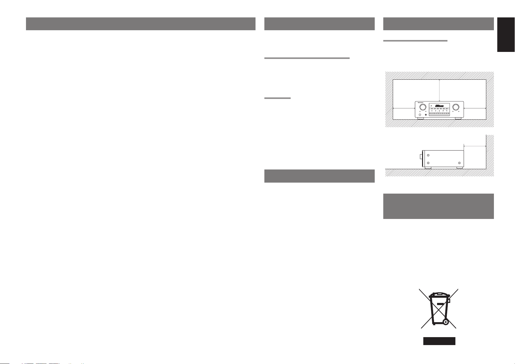
TABLE OF CONTENTS FOREWORD
RECORDER
F/P
BAND
BALANCE
SPEAKERS
SOURCE
DIRECT
SPEAKERS
DISPLAY OFF
BASS
TREBLE
VCR
T-MODE
CLEAR
AUTO TUNE
MEMORY
DVD
DSS
AUX
TUNERCDCD
PHONO
DOWN
VOLUME
MULTI JOG
UP
RECEIVER SR4021
SLEEP
DIMMER
MUTE
STANDBY
PHONES
POWER ON/OFF
FOREWORD ...........................................1
INTRODUCTION ....................................1
PRECAUTIONS ......................................1
A NOTE ABOUT RECYCLING ..............1
FEATURES ............................................. 2
ACCESSORIES ......................................2
FRONT PANEL ......................................3
FL DISPLAY ........................................................................4
REAR PANEL .........................................5
REMOTE CONTROL OPERATION .......6
FUNCTION AND OPERATION ..........................................6
THE CONTROLLABLE FUNCTION TABLE ......................7
USING THE REMOTE CONTROL UNIT ...........................7
FUNCTION AND OPERATION ..........................................8
CONNECTIONS .....................................8
CONNECTING SPEAKERS ...............................................8
CONNECTING AUDIO COMPONENTS ............................ 9
CONNECTING VIDEO COMPONENTS ..........................10
CONNECTING THE REMOTE CONTROL JACKS .........10
CONNECTING THE ANTENNA TERMINALS .................11
BASIC OPERATION (PLAY BACK) .....12
SELECTING AN INPUT SOURCE ...................................12
ADJUSTING THE MAIN VOLUME ..................................12
ADJUSTING THE TONE (BASS & TREBLE) AND
BALANCE CONTROL ......................................................12
TEMPORARILY TURNING OFF THE SOUND ....................12
USING THE SLEEP TIMER .............................................13
LISTENING THROUGH HEADPHONES .......................13
RECORDING A SOURCE ................................................13
BASIC OPERATION (TUNER) .............14
LISTENING TO THE TUNER ...........................................14
PRESET MEMORY ..........................................................15
RDS OPERATION ............................................................16
TROUBLESHOOTING .........................17
TECHNICAL SPECIFICATIONS ..........18
DIMENSIONS ......................................18
This section must be read before any connection is
made to the mains supply.
EQUIPMENT MAINS WORKING SETTING
Your Marantz product has been prepared to comply
with the household power and safety requirements
that exist in your area.
SR4021 can be powered by 230V AC only.
COPYRIGHT
Recording and playback of any material may
require consent. For further information refer to the
following:
— Copyright Act 1956
— Dramatic and Musical Performers Act 1958
— Performers Protection Acts 1963 and 1972
— any subsequent statutory enactments and
orders
INTRODUCTION
Thank you for purchasing the Marantz SR4021
Receiver.
This remarkable component has been engineered
to provide you with many years of home theater
enjoyment. Please take a few minutes to read this
manual thoroughly before you connect and operate
the SR4021.
As there are a number of connection a nd confi guration
options, you are encouraged to discuss your own
particular home theater setup with your Marantz A/V
specialist dealer.
PRECAUTIONS
CAUTIONS ON INSTALLATION
For heat dispersal, leave at least 20 cm/8 ins. of
space between the top, back and sides of this unit
and the wall or other components.
• Do not obstruct the ventilation holes.
0.2 m (8 ins.)
or more
0.2 m (8 ins.)
or more
RECEIVER SR4021
MULTI JOG
1
SPEAKERS
2
DISPLAY OFF
CLEAR
MEMORY
BASS
TREBLE
SLEEP
DIMMER
PHONO
TUNER
STANDBY
PHONES
POWER ON/OFF
VOLUME
0.2 m (8 ins.)
DOWN
F/P
BAND
BALANCE
RECORDER
21 AUX
UP
T-MODE
AUTO TUNE
SPEAKERS
2
1
SOURCE
DIRECT
MUTE
VCR
DSS
DVD
or more
0.2 m (8 ins.)
or more
A NOTE ABOUT
RECYCLING
This product’s packaging materials are recyclable
and can be reused. This product and the accessories
packed together are the applicable product to the
WEEE directive except batteries.
Please dispose of any materials in accordance with
your local recycling regulations.
When discarding the unit, comply with your local
rules or regulations.
Batteries should never be thrown away or incinerated
but dis
posed of in accordance with your local
regulations concerning chemical wastes.
ENGLISH
1
Page 6
ENGLISH
FEATURES
■ High quality full discrete power amplifi er
80W+80W (8 ohms, 20 Hz – 20 kHz, 0.08%
THD)
■ Speaker 1/2 switching
You can switch the speaker 1/2 via remote control
unit.
■ Four A/V inputs (DVD, DSS, VCR and AUX)
■ One A/V output (VCR) and one video monitor
output
■ Four audio inputs and Two audio outputs
Built in PHONO equalizer (MM)
■ Simulcast playback video signal of video
source with audio source
■ 30 station AM/FM random preset memory
■ Bass and treble tone controls
■ Source direct
You can bypass the tone and balance controls,
routing the audio signal directly to provide the
pure sound quality.
■ PRE OUT and MAIN IN jacks
■ Sleep timer
■ Dimmer control
RDS function
■
Radio Data System (RDS) provides information
on FM broadcasts.
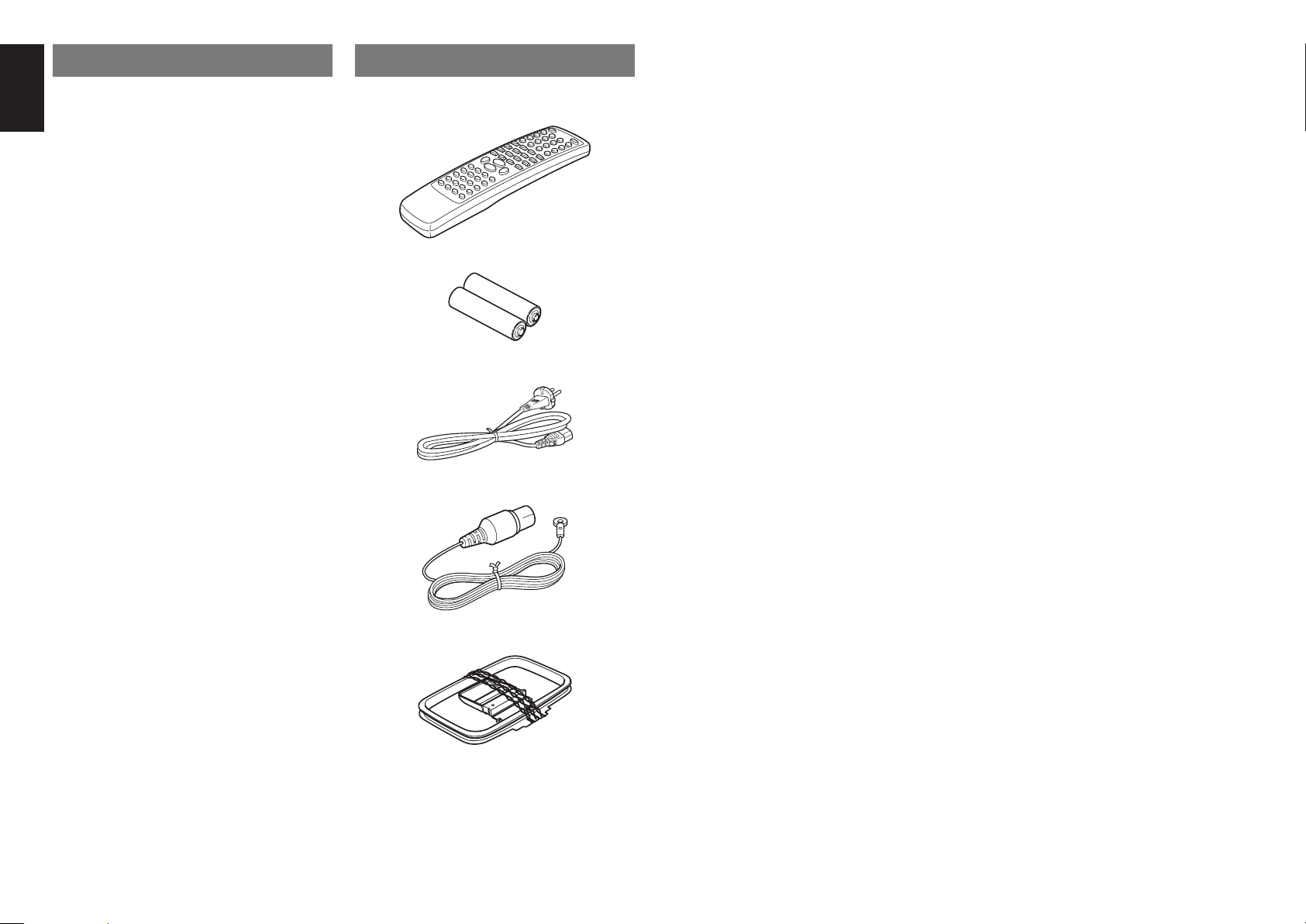
ACCESSORIES
Check the supplied accessories.
Remote control unit (RC4021SR)
Batteries (AAA, R03, UM-4) 2 pcs
AC Power cord
FM Antenna
AM Loop Antenna
Registration Card
User Guide
2
Page 7
FRONT PANEL
RECORDER
F/P
BAND
BALANCE
SPEAKERS
SOURCE
DIRECT
SPEAKERS
DISPLAY OFF
BASS
TREBLE
VCR
T-MODE
CLEAR
AUTO TUNE
MEMORY
DVD
DSS
AUX
TUNER
CD
PHONO
DOWN
VOLUME
MULTI JOG
UP
RECEIVER SR4021
SLEEP
DIMMER
MUTE
STANDBY
PHONES
POWER ON/OFF
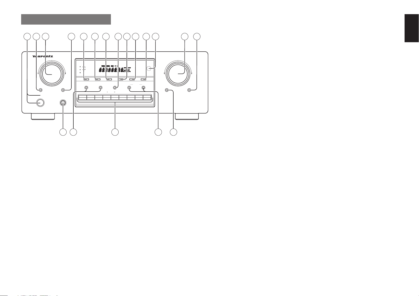
t CLEAR button
Press this button to cancel the tuner preset station or
preset scan tuning. (See page 15)
!5 MUTE button
Press this button to mute the output to the speakers.
Press it again to return to the previous volume level.
STANDBY
POWER ON/OFF
321
MULTI JOG
SLEEP
4 5 6 7 98 10 11 12 13 14
RECEIVER SR4021
1
SPEAKERS
2
DISPLAY OFF
CLEAR
MEMORY
DIMMER
PHONES
BASS
CD
PHONO
q POWER switch and STANDBY
indicator
Press the button to turn the power ON, and press
again to turn it OFF. If the POWER switch is in the
ON position, the power of this unit can be turned ON/
OFF by pressing the POWER button on the remote
control unit.
When this unit is in the standby mode with the
POWER switch set to the ON position, pressing one
of the FUNCTION SELECTOR buttons also allows to
turn the power on.
The STANDBY indicator lights up when this unit is
in the standby mode (power OFF) by the remote
control unit.
w SLEEP (Sleep timer) button
This button is used for setting the sleep timer.
y MEMORY button
Press this button to enter the tuner preset memory
numbers or station names. (See page 15)
!6 SPEAKERS (system 1/2) buttons
These buttons are used to select the speaker
system(s) connected to the SPEAKER SYSTEM
ENGLISH
1/2 terminals on the rear panel. The corresponding
VOLUME
u BAND button
Press this button to switch between FM and AM in
F/P
BAND
BALANCE
TREBLE
RECORDER
TUNER
21 AUX
AUTO TUNE
1
VCR
SPEAKERS
T-MODE
2
DVD
DSS
DOWN
MUTE
UP
SOURCE
DIRECT
the TUNER mode.
i BALANCE control button
Press this button and turn MULTI JOG control knob
to vary the output level of the left and right channel. If
this button is pressed in Source Direct Mode, Source
Direct is cancelled.
indicators of the active speakers light. If headphone are
connected, both 1 and 2 are set off automatically.
!7 Function selector buttons
These buttons are used to select the sources. The
selected source name will be displayed on the front
display.
The video function selector, such as DVD, VCR, DSS
and AUX selects video and audio simultaneously.
Audio function sources such as PHONO, CD,
TUNER ,RECORDER 1 and RECORDER 2 may be
o F (Frequency)/P (Preset) button
During reception of AM or FM, you can change
the function of the UP/DOWN buttons for scanning
151618 1719
e MULTI JOG control knob
This knob is used in conjunction with the BASS,
TREBLE and BALANCE buttons, and is used to
adjust tone control and balance control. Also, this
knob is used for the TUNING/PRESET search in
the TUNER mode. In the tuning mode, the reception
frequency is tuned up or down. Turning the control
in the clockwise direction tunes the frequency up.
Turning the control in the counterclockwise direction
tunes the reception frequency down. In the preset
mode, the selection of the preset channel is moved
up or down.
r DIMMER button
When this button is pressed once display is dimmed.
When this button is pressed twice, the display is
turned off and the “DISPLAY OFF” indicator lights
up.
Press this button again to turn on the display again.
frequencies or selecting preset stations by pressing
this button.
!0 AUTO TUNE button
When this button is pressed and the MULTI JOG
knob is turned, auto scan function of the tuner
frequency starts.
!1 T-MODE button
Press this button to select the auto stereo mode or
mono mode when the FM band is selected.
!2 INFRARED receiving sensor
window
This window receives infrared signals from the
remote control.
!3 VOLUME control knob
Adjusts the overall sound level. Turning the control
clockwise increases the sound level.
!4 SOURCE DIRECT button
When this button is pressed, the audio signal will
selected in conjunction with a Video source.
This feature (Sound Injection) combines a sound
from one source with a picture from another.
Choose the video source fi rst, and then choose a
different audio source to activate this function.
!8 BASS/TREBLE control buttons
Press these buttons and turn MULTI JOG control
knob to adjust the tone by controlling the level of
two frequency bands. To adjust the bass effect,
press BASS button. To adjust the treble effect, press
TREBLE button. If these buttons are pressed in
Source Direct Mode, Source Direct is cancelled.
!9 PHONES jack for stereo
headphones
Conventional dynamic headphones can be plugged
in here.
Note:
When using headphones, the speaker 1 and/or 2 are
switched automatically to OFF and the sound from
the speakers is muted. The speaker 1 and/or 2 return
to the previous setting as soon as the plug is removed
from the jack.
bypass the balance and tone control circuit to provide
the pure sound quality.
To return not to bypass the balance and tone control
circuit, press SOURCE DIRECT button again.
3
Page 8
ENGLISH
FL DISPLAY
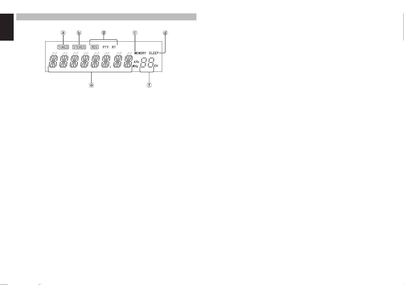
a TUNED indicator
This indicator illuminates when a station is being
received with suffi cient signal strength to provide
acceptable listening quality.
b STEREO indicator
This indicator illuminates when an FM station is
being tuned in stereo condition.
c MEMORY indicator
When the MEMORY button is pressed, this indicator
blinks for about 5 seconds.
d SLEEP indicator
This indicator lights up while the sleep timer function
is in use.
e Frequency/Character display
This displays the selected station frequency or the
corresponding words when selecting a program
source.
f Preset number display
Shows the selected preset number.
g RDS indicators
These indicators illuminate when this unit is receiving
RDS data.
4
Page 9
REAR PANEL
230V 50/60Hz
IN
SYSTEM 2
150W 1A MAX.
AC OUTLET
SWITCHED
IN
AM
FM
(
75
)
PHONO
IN
OUT
OUT
DSS
GND
AUX
VIDEO
SYSTEM 1
CONTROL
REMOTE
GND
VCR
IN
OUT
L
ANTENNA
IN
OUT
OUT
OUT
IN
IN
IN
IN
OUT
IN
IN
(CD-R)
(TAPE)
AUX
CD
DSS
PRE
DVD
RECORDER 2
MAIN
VCR
RECORDER 1
IN
R
DVD
AUDIO
R
MONITOR
FLASHER
AC IN
L
R
L
MODEL NO. SR4021
SYSTEM 1 1 : :
4 - 16 OHMS
SYSTEM 2 2 : :
4 - 16 OHMS
SYSTEM
1+2 : :
8 - 16 OHMS
1 8
22
ANTENNA
AM
GND
(
)
FM
75
ININOUT
IN
IN
CD
RECORDER 1
RECORDER 2
(CD-R)
(TAPE)
PHONO
GND
IN
L
R
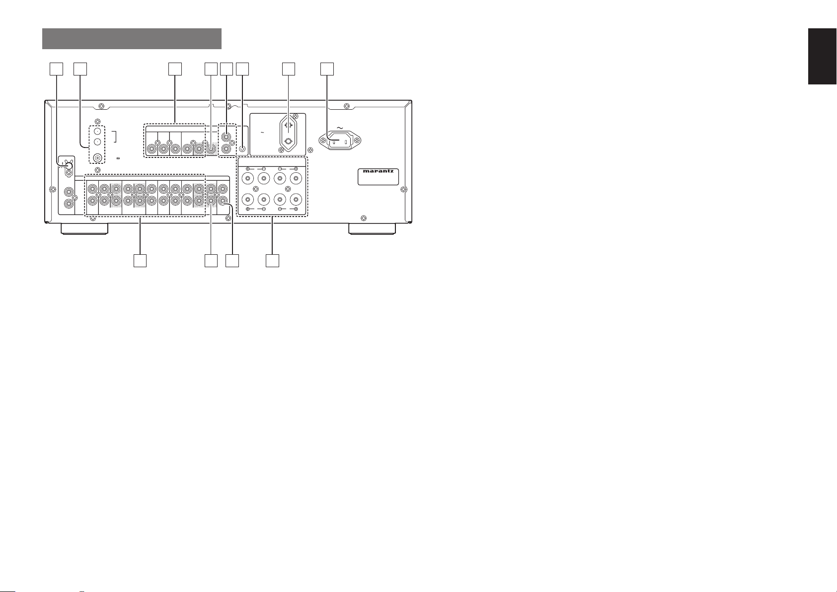
z GND (ground) terminal
Connect the grounding wire from the analog turntable
to this terminal.
x Antenna terminals
FM antenna terminal
For connecting the supplied FM antenna or for
connecting an external FM antenna with a coaxial
cable, or for connecting a cable network.
AM antenna and ground terminal
For connecting the supplied AM loop antenna. Use
the terminals marked “AM” and “GND”.
The supplied AM loop antenna will provide good AM
reception in most areas. Position the loop antenna to
the best reception.
c VIDEO IN/OUT
(AUX, DSS, DVD, VCR)
These are the video inputs and output. There are 4
video inputs and 1 video output. Connect VCR, DVD
players, and other video components to the video
inputs.
The 1 video output can be used to be connected to
video tape recorder for making recording.
v MONITOR output jack
Connect to the TV’s video input (VIDEO IN) jack.
DSS
AUX
IN
AUDIO
IN
OUT
AUX
DSS
3 4 5 6 7
VIDEO
DVD
INININ
ININOUT
IN
IN
IN
DVD
REMOTE
CONTROL
VCR
MONITOR
OUT
OUT
PRE
MAIN
VCR
OUT
IN
1112
AC OUTLET
230V 50/60Hz
IN
SWITCHED
150W 1A MAX.
FLASHER
IN
OUT
SYSTEM
SYSTEM
SYSTEM
R
SYSTEM 2
R
SYSTEM 1
10
b REMOTE CONTROL IN/OUT
terminals
Connect to a Marantz component equipped with
remote control (RC-5) terminals.
n FLASHER IN (Flasher input
terminal)
This terminal is to control the unit from another
zone.
Connect the control signal from a Keypad, etc.
m AC OUTLET
Connect the AC power cord of component such as a
DVD or CD player to this outlet.
The marked SWITCHED provides power only when
the SR4021 is turned on a nd is useful for components
which you use every time you play your system.
Caution:
• In order to avoid potential turn-off thumps, anything
plugged into these outlets should be powered up
before the SR4021 is turned on.
• The capacity of this AC outlet is 150W. Do not
connect devices that consume electricity more than
the capacity of this AC outlet. If the total power
consumption of the connected devices exceeds the
capacity, the protection circuit shuts down the power
supply.
, AC IN
Connect to supplied an AC power cord, and connect
to an AC power outlet.
SR4021 has to be powered by 230V AC only.
. Speaker terminals
ENGLISH
Connect your speaker system(s) to these terminals.
There are two sets of terminals, so you can connect
either 1 and/or 2 speaker systems.
AC IN
⁄0 MAIN IN jacks
Use these jacks to connect an extension pre amplifi er
or graphic equalizer.
4 - 16 OHMS
4 - 16 OHMS
1+2
8 - 16 OHMS
L
MODEL NO. SR4021
When a graphic equalizer is to be connected,
connect its output jacks with the MAIN IN jacks on
this unit.
When not used, leave these jacks connected with the
supplied connecting pins.
L
⁄1 PRE OUT jacks
Use these jacks to connect an extension power
amplifi er or graphic equalizer.
When a graphic equalizer is to be connected,
connect its input jacks with the PRE OUT jacks on
9
this unit.
When not used, leave these jacks connected with the
supplied connecting pins.
⁄2 AUDIO IN/OUT
(PHONO, CD, RECORDER 1,
RECORDER 2)
These are the analog audio inputs and outputs. There
are 8 audio inputs (4 of which are linked to video
inputs) and 3 audio outputs (1 of which is linked to
video output). The audio jacks are nominally labeled
for recorder1 (CD recorder) recorder2 (cassette tape
deck), compact disc players, DVD players and etc....
The audio inputs and outputs require RCA-type
connectors.
5
Page 10
ENGLISH
REMOTE CONTROL
OPERATION
25
24
23
22
21
20
19
18
17
16
10
11
12
13
14
15
FUNCTION AND OPERATION
The provided remote control unit can be used to
control a Marantz audio/visual component such as a
DVD player, CD player.
The POWER button, numeric buttons and control
buttons are used in common across different input
1
2
3
5
6
7
source components.
The input source controlled with the remote control
unit changes when one of the input selector butto
on the remote control unit is pressed.
• Example
4
To select the DVD as the input source and play
the DVD player.
Press the DVD button. The input selector of the
SR4021 is switched to DVD and the remote control
unit is set for control of the DVD player.
Press the PLAY button on the remote control
unit.
8
9
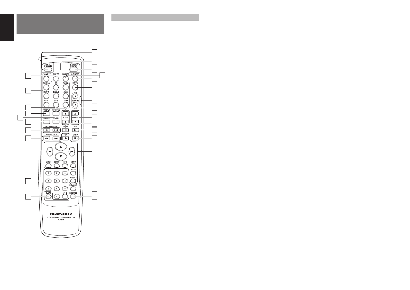
z MAIN POWER button
Press to switch the power of the SR4021 ON or
STANDBY.
x Transmitting indicator
Lights up during a button is pressed and an infrared
signal is sending.
c SOURCE POWER button
Press to switch the power of the source component
after pressing the function selector button.
v DIMMER button
When this button is pressed once, the display
is dimmed. When this button is pressed twice,
the display is turned off and the “DISPLAY OFF”
indicator lights up.
Press this button again to turn on the display again.
b S (Source)-DIRECT button
When this button is pressed, the audio signal will
bypass the balance and tone control circuit to provide
the pure sound quality.
n MUTE button
Press this button decrease the sound temporarily.
Press this button again to return to the previous
sound level.
m VOLUME up (3) /down (4) buttons
Press to adjust the volume control of SR4021.
, BASS up (3) /down (4) buttons
These buttons are used to adjust the tone control of
low frequency sound.
. TREBLE up (3) /down (4) buttons
These buttons are used to adjust the tone control of
high frequency sound.
⁄0 T-DISP. / PAUSE button
(When tuner mode is selected)
This button is used to select display mode function in
RDS (Radio Data System).
(When CD/RECORDER/VCR/DVD mode is selected)
ns
Press this button to pause each programs.
⁄1 PTY / PLAY button
(When tuner mode is selected)
Press this button to display the programme type
information of current station.
(When CD/RECORDER/VCR/DVD mode is selected)
Press this button to playback each programs.
⁄2 BAND / STOP button
(When tuner mode is selected)
Press this button to switch between FM and AM.
(When CD/RECORDER/VCR/DVD mode is selected)
Press this button to stop each programs.
⁄3 Cursor, ENTER, MENU, etc.
buttons
These buttons are used when operating the DVD
player, VCR, etc. The function of these buttons are
dependent on the function button selected. For the
controllable functions of each input function, please
refer to controllable table on page 7.
⁄4 F.DIR / ANGLE button
(When tuner mode is selected)
Press this button to change tuner mode to Frequency
Direct Call mode. You can call your desired frequency
with numeric button of the remote control unit in this
mode.
⁄5 MEMO / PROG. button
Memory enable button for various preset functions.
⁄6 CLEAR button
This button is used to cancel for certain memory or
programming operations.
⁄7 Numeric buttons 0 to +10
These buttons are used to enter figures in the
selection of a tuner preset station and station name
preset or to set select a DVD chapter or title and a CD
track number, etc. The functions of these buttons are
dependent on the function button selected.
⁄8 TUNE/SEARCH buttons
(When tuner mode is selected)
These button are used to increase or decrease the
frequency to which the tuner is currently tuned. Press
and hold one of these buttons to initiate the auto
tuning operation.
⁄9 CHANNEL / SKIP buttons
(When tuner mode is selected)
These button are used to move up or down through
the preset stations.
¤0 T-MODE button
(When tuner mode is selected)
Press this button to select the auto stereo mode or
mono mode when the FM band is selected.
¤1 P.SCAN button
(When tuner mode is selected)
This button is used to start preset scan when TUNER
mode is selected in SR4021.
¤2 TV INPUT button
Press this button to select TV input mode.
¤3 SPKR 1/2 button
Press this button to select the speaker system (or
systems) which is to be used. Each time it is pressed,
the setting is selected in the following sequence in
turn: 1 only ON → 2 only ON → 1 and 2 ON → 1
and 2 OFF → 1 only ON, and so on. The speaker
indicator (or indicators) corresponding to the speaker
(or speakers) which has been set to the active status
lights.
When headphones have been connected, speakers
1 and 2 are automatically set to OFF.
¤4
Input selector buttons / FUNCTION
SELECTOR buttons
(AUDIO / VIDEO INPUT)
These buttons are used to select a Audio or Video
source component. When one of these buttons
is pressed, the input function of the SR4021 is
changed.
Au dio function sources such as PHONO, CD,
TUNER, RECORDER1 and RECORDER2 may be
selected in conjunction with a Video source.
This feature (Sound Injection) combines a sound
from one source with a picture from another.
Choose the video source fi rst, and then choose a
different audio source to activate this function.
¤5 SLEEP button
This button is used for setting the sleep timer.
6
Page 11
THE CONTROLLABLE FUNCTION TABLE
CD
SOURCE POWER POWER ON/
CHANNEL/SKIP S PREV PREV PREV CH- CH- PREV
CHANNEL/SKIP
T-DISP. ; PAUSE PAUSE PAUSE PAUSE - PAUSE
PTY 2 PLAY PLAY PLAY PLAY - PLAY
TUNE/SEARCH
TUNE/SEARCH
REC 0 - REC REC REC - BAND 9 STOP STOP STOP STOP - STOP
Cursor - - - Cursor Cursor Cursor
ENTER - - - OK OK OK
SETUP - - - - - SETUP
INFO - - - DISPLAY DISPLAY DISPLAY
MENU SWITCH
0-9 INPUT
+10 -----Input +10
AUDIO - - - AUDIO AUDIO AUDIO
SUBTITLE - - - - - SUBTITLE
F.DIR/ANGLE - - - - - ANGLE
CLEAR INPUT
MEMO/PROG. CALL
STANDBY
T NEXT NEXT NEXT CH+ CH+ NEXT
Q FR FR FR FR - FR
R FF FF FF FF - FF
DISPLAY
NUMERIC
CLEAR
PROGRAM
RECORDER 1
(CDR)
POWER ON/
STANDBY
SWITCH
DISPLAY
INPUT
NUMERIC
INPUT
CLEAR
CALL
PROGRAM
RECORDER 2
(TAPE)
POWER ON/
STANDBY
SWITCH
DISPLAY
INPUT
NUMERIC
INPUT
CLEAR
CALL
PROGRAM
VCR DSS DVD
POWER ON/
STANDBY
CALL UP
MENU
INPUT
NUMERIC
INPUT
CLEAR
POWER ON/
STANDBY
CALL UP
MENU
INPUT
NUMERIC
INPUT
- - CALL
CLEAR
POWER ON/
STANDBY
MENU
CALL UP
MENU
INPUT
NUMERIC
INPUT
CLEAR
PROGRAM
USING THE REMOTE CONTROL UNIT
REMOTE CONTROL OPERATIONAL RANGE
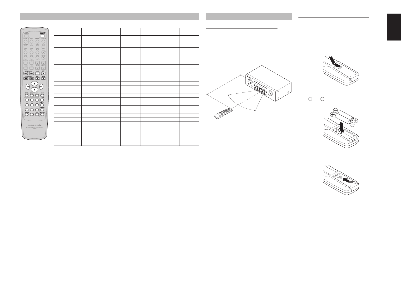
The distance between the transmitter of the remote
control unit and the IR SENSOR of the SR4021
should be less than about 5 meters.
If the transmitter is pointed to a direction other than
the IR SENSOR or if there is an obstacle between
them, remote control may not be possible.
SR4021
Approx. 5 m
60°
Remote control unit (RC4021SR)
PREPARING THE REMOTE CONTROL UNIT
The life of the batteries used with the remote control
unit is about 4 months with normal use. Also be sure
to replace batteries earlier when you notice that they
are getting weak.
Remove the back cover.
1.
2. Insert the new batteries (AAA type) with correct
and polarity.
ENGLISH
Close until it clicks shut.
3.
7
Page 12
ENGLISH
FUNCTION AND OPERATION
REMOTE CONTROL CODE SETTING
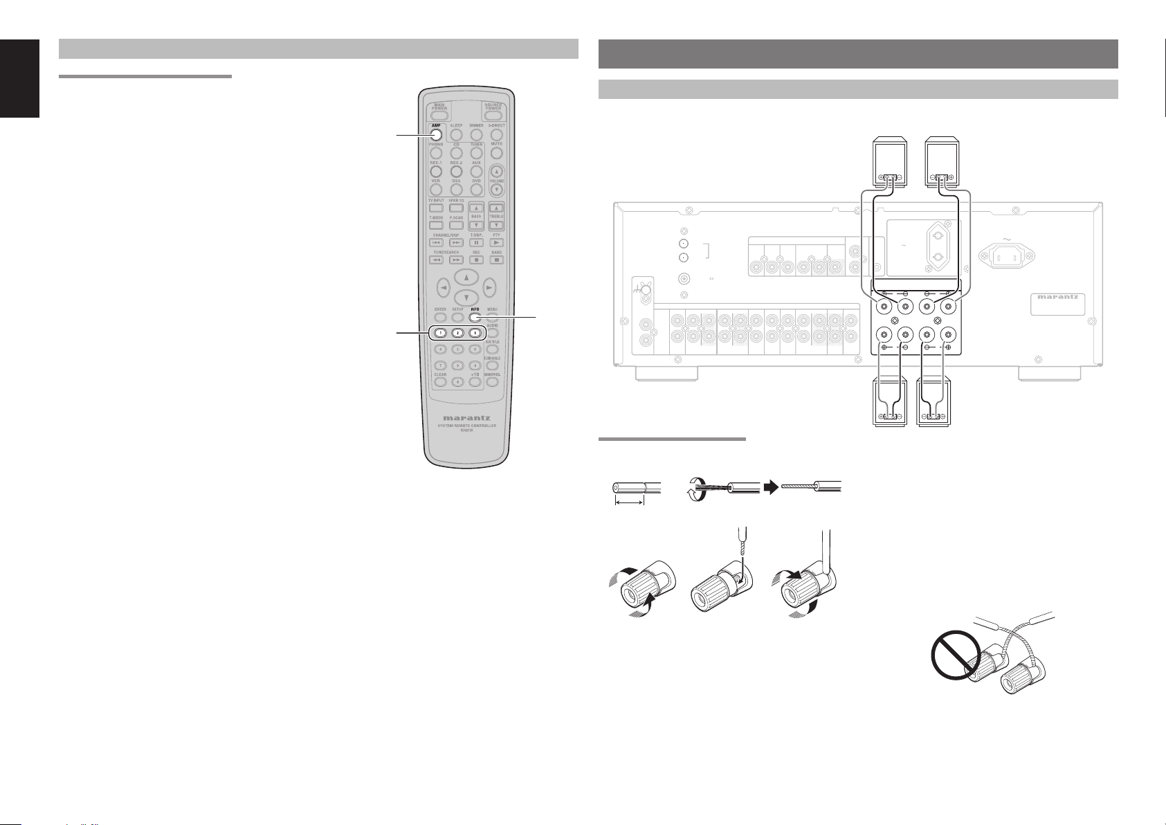
The remote control unit contains 3 sets of remote
control codes, and it can be used to control up to 3
receivers in one location. To control a second or third
receiver, select the remote control code as explained
below. The selected receiver can be operated from
the remote control.
• When the unit is shipped from the factory, the main
unit and remote control are set to RECEIVER1.
RECEIVER2
1.
To set the remote control to RECEIVER2,
hold down both the AMP button and 2 number
button on the remote control for at least fi ve
seconds.
RECEIVER3
To set the remote control to RECEIVER3,
hold down both the AMP button and 3 number
button on the remote control for at least fi ve
seconds.
Also set the main unit’s remote control setting
2.
to the same setting as the remote control.
change main unit’s remote control setting,
hold down both the AMP and INFO buttons
on the remote control; the remote control
setting (“RECEIVER 1”, “RECEIVER 2” or
“RECEIVER 3”) will be displayed in the display
window on the main unit and main unit setting
will be changed same setting as remote
control.
Notes:
• To set the remote control back to RECEIVER1, hold
down both the AMP button and 1 number button on
the remote control for at least fi ve seconds.
If the batteries in the remote control are replaced
•
while the remote control is set to RECEIVER2 or
RECEIVER3, the setting will revert to RECEIVER1.
To
AMP
1, 2, 3
INFO
CONNECTIONS
CONNECTING SPEAKERS
ANTENNA
AM
GND
FM (75
(CD-R) (TAPE)
PHONO
GND
IN
L
R
CONNECTING SPEAKER WIRE
1. 2.
10 mm
(3/8inch)
3. 4. 5.
)
AUDIO
INOUT OUT ININ ININOUTIN IN
AUX
IN
IN
AUXCD DSS PREDVDRECORDER 2 MAINVCRRECORDER 1
DSS
VIDEO
DVD
ININ OUTIN OUT
System 2
Right Left
REMOTE
CONTROL
VCR
MONITOR
OUT
IN
FLASHER
OUT
AC OUTLET
230V 50/60Hz
SWITCHED
150W 1A MAX.
IN
SYSTEM 1 : 4 - 16 OHMS
SYSTEM 2 : 4 - 16 OHMS
SYSTEM 1+2 : 8 - 16 OHMS
R
R
R L
R L
SYSTEM 2
SYSTEM 2
SYSTEM 1
SYSTEM 1
L
L
AC IN
MODEL NO. SR4021
Right Left
System 1
Caution:
• Be sure to use speakers with the specifi ed impedance
as shown on the rear panel of this unit.
• To prevent damage to circuitry, do not let the bare
speaker wires touch each other and do not let them
touch any metal part of this unit.
• Do not touch the speaker terminals when the power
is on. It may cause you to receive an electric shocks.
• Do not connect more than one speaker cable to one
speaker terminal. Doing so may damage this unit.
Strip away approx. 10 mm (3/8inch) of wire
1.
insulation.
Twist the bared wire ends tight, to prevent short
2.
circuits.
Loosen the knob by turning it counterclockwise.
3.
4. Insert the bare part of the wire into the hole in
side of each terminal.
Tighten the knob by turning it clockwise to
5.
secure the wire.
Note:
Be sure to connect the positive and negative cables for
the speaker properly. If they are miss-connected, the
signal phase will be reversed and the signal quality
will be corrupted.
8
Page 13
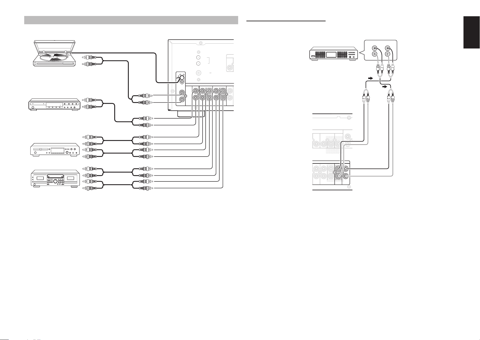
CONNECTING AUDIO COMPONENTS
CONNECTING PRE OUT/MAIN IN JACKS
Turn table
CD player
CD recorder
Tape Deck
PHONO
PHONO
Graphic equalizer
or
processor
ANTENNA
AM
GND
GND
GND
IN
IN
L
L
R
R
FM (75
(CD-R) (TAPE)
AUX
IN
)
AUDIO
AUDIO
ININOUT OUTININ
INOUT OUTININ
AUXCD RECORDER 2RECORDER 1
VIDEO
DVD
IN OUTIN OUT
ININ
VCR
REMOTE
CONTROL
IN
MONITOR
OU
OUT
PREDVD MAINVCR
PRE MAIN
OUT
IN
OUT IN
OUT IN
L
R
RL RL
RL RL
L
ENGLISH
R
The output audio signal from the RECORDER 1 OUT jack and the RECORDER 2 OUT jack is the same signal
which is currently selected.
Caution:
• Do not connect this unit and other components to mains power until all connections between components have been
completed.
Notes:
• Insert all plugs and connectors securely. Incomplete connections may make noise.
• Be sure to connect the left and right channels properly.
Red connectors are for the R (right) channel, and white connectors are for the L (left) channel.
• Be sure to connect input and output properly.
• Refer to the instructions for each component that is connected to this unit.
• Do not bind audio/video connection cables with power cords and speaker cables this will result in generating a hum
or other noise.
Connecting with external power amplifi er
This receiver has enough power for normal listening but PRE OUT jacks are prepared to connect external
power amplifi ers for higher power output. In such a case, connect these jacks to the MAIN IN jacks or AUX IN
jacks of the power amplifi er.
Connecting with graphic equalizer
Use PRE OUT and MAIN IN jacks to connect a graphic equalizer or other analog audio processor.
Note:
When not used, leave these jacks connected with the supplied connecting pins.
9
Page 14
ENGLISH
L
U
N
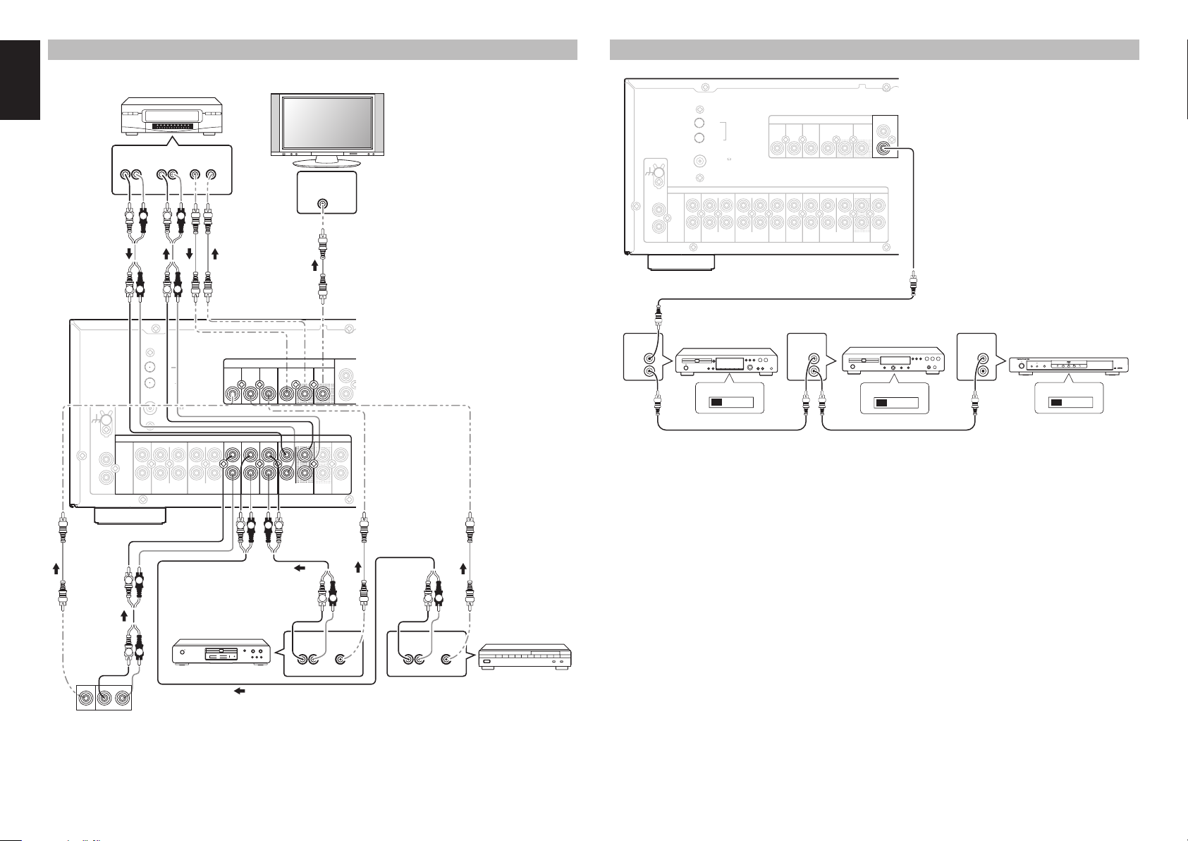
CONNECTING VIDEO COMPONENTS
CONNECTING THE REMOTE CONTROL JACKS
10
GND
PHONO
L
R
IN
AUDIO
OUT
LR
VCR
AUDIO
IN
LR
L R L R
L RL R
ANTENNA
AM
GND
FM (75
ININ
(CD-R) (TAPE)
L R
VIDEO
OUT IN
IN
)
AUDIO
AUDIO
IN
INOUT OUT ININ
IN
AUXCD DSS PREDVDRECORDER 2 MAINVCRRECORDER 1
DVD
DSS VCRDVD
DSSAUX
ININ OUTIN OUT
ININ OUTIN
DSSAUX DVD VCR
L R
Monitor
VIDEO
IN
CVBS
VIDEO
VIDEO
VCR
ININ OUTIN
LR
REMOTE
CONTRO
I
MONITOR
MONITOR
OUT
O
OUTIN
OUT
IN
LR
LR
DVD player
LR
OUTOUT
LVIDEO R
VIDEO camera etc..
AUDIO
LR
OUT
VIDEO
OUT
AUDIO
OUT
LR
VIDEO
OUT
Notes:
• Insert all plugs and connectors securely. Incomplete connections will result in the generation of noise.
• Be sure to connect the left and right channels properly.
Red connectors are used for the R (right) channel, and white connectors are used for L (left) channel.
• Be sure to connect input and output of video signal properly.
Satellite tuner
ANTENNA
IN
IN
AUXCD DSS PREDVDRECORDER 2 MAINVCRRECORDER 1
DVD
DSSAUX
ININ OUTIN OUT
REMOTE
CONTROL
IN
OUT
VIDEO
VCR
PHONO
L
R
REMOTE
CONTROL
IN
OUT
AM
GND
)
GND
IN
FM (75
ININ
(CD-R) (TAPE)
AUDIO
INOUT OUT INININOUTIN
CD recorder
EXTERNAL INTERNAL
q
You can control other Marantz products through
this unit with the remote control by connecting the
REMOTE CONTROL terminals on each unit.
The signal transmitted from the remote control is
received by the remote sensor on this unit. Then the
signal is sent to the connected device through this
terminal. Therefore you only need to aim the remote
at one unit. Also, if a Marantz power amplifi er (some
models exclu
ded) is connected to one of these
terminals, the power amplifier’s, power switch is
synchronized with this unit’s power switch.
Set the REMOTE CONTROL SWITCH on the units,
other than the main unit to EXT.(EXTERNAL) for this
feature.
REMOTE
CONTROL
IN
MONITOR
OUT
OUT
OUT
CD player
EXTERNAL INTERNAL
REMOTE
CONTROL
IN
OUT
DVD player
DVD PLAYER DV4600
STANDBY
POWER ON/STANDBY
FL OFFVIRTUAL
OPEN/CLOSE
EXTERNAL INTERNAL
w
Whenever external infrared sensors or similar
devices are connected to RC-5 IN of the SR4021,
be sure to always disable operation of the infrared
sensor on the main unit by using the following
procedure.
Hold down the SLEEP button and DIMMER
1.
button on the front panel at the same time for 3
seconds.
The setting “IR=ON” is shown on the FL
2.
DISPLAY.
Turn the MULTI JOG knob to change this to
3.
“IR=OFF”.
Press the MEMORY button. Once this setting
4.
is made, the infrared sensor on the main unit is
disabled.
Note:
Be sure to set to “IR=ON” when external infrared
sensors or similar devices are not connected.
Otherwise, the main unit will be unable to receive
remote control commands.
5. To restore the original setting, perform steps 1
to 4 to set to “IR=ON”.
Page 15
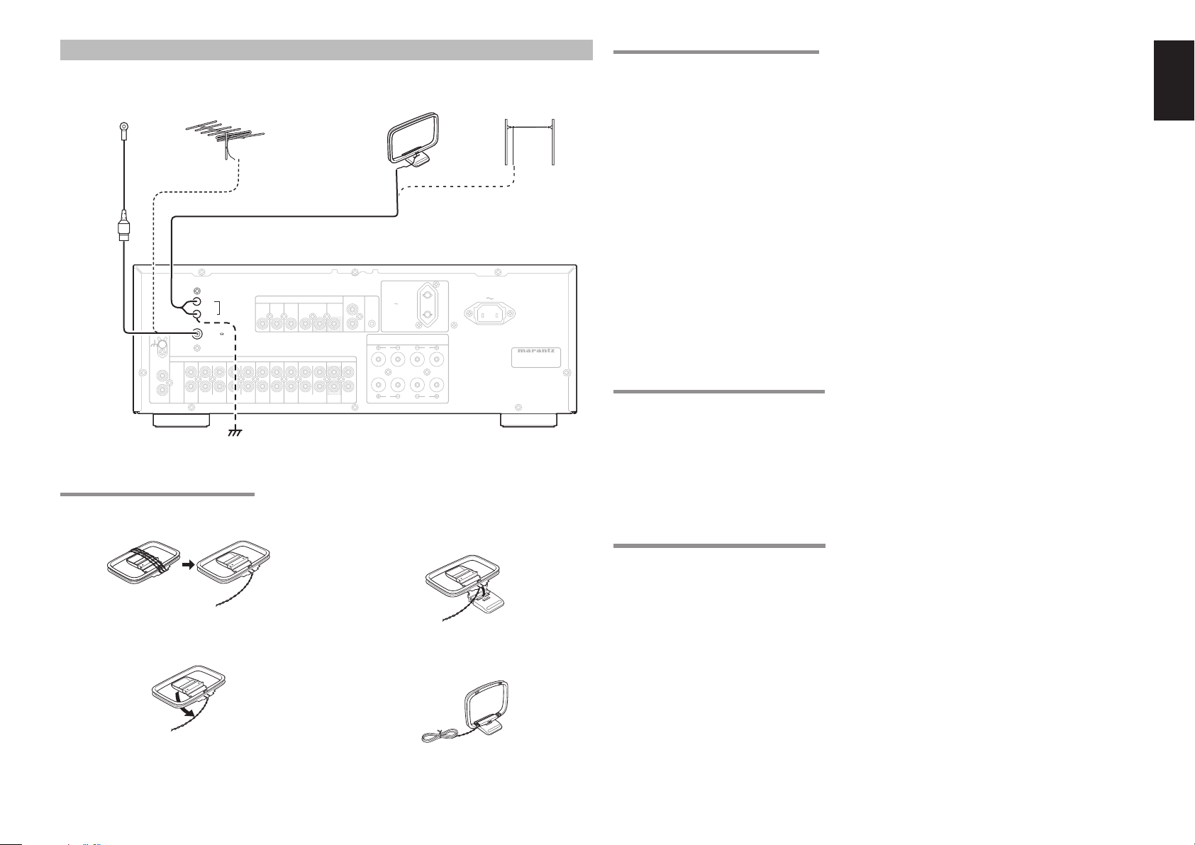
CONNECTING THE ANTENNA TERMINALS
FM
Antenna
GND
PHONO
IN
L
R
ASSEMBLING THE AM LOOP ANTENNA
1. Take out the connection line.
2. Bend the base part in the reverse direction.
FM External
ANTENNA
AM
GND
FM (75
(CD-R) (TAPE)
Antenna
)
INOUT OUT INININOUTIN
DSSAUX
DVD
IN
AUDIO
IN
AUXCD DSS PREDVDRECORDER 2 MAINVCRRECORDER 1
VIDEO
ININ OUTIN OUT
AM Loop
Antenna
REMOTE
AC OUTLET
CONTROL
230V 50/60Hz
VCR
IN
MONITOR
OUT
3.
SWITCHED
150W 1A MAX.
FLASHER
IN
OUT
SYSTEM 1 : 4 - 16 OHMS
SYSTEM 2 : 4 - 16 OHMS
SYSTEM 1+2 : 8 - 16 OHMS
R
L
SYSTEM 2
R L
SYSTEM 1
Insert the hook at the bottom of the loop part
into the slot at the base part.
4. Place the antenna on stable surface.
AM External
Antenna
AC IN
MODEL NO. SR4021
CONNECTING THE SUPPLIED ANTENNAS
Connecting the supplied FM antenna
The supplied FM antenna is for indoor use only.
During use, extend the antenna and move it in various
directions until the clearest signal is received.
Fix it with push pins or similar implements in the
position that will cause the least amount of distortion.
If you experience poor reception quality, an outdoor
antenna may improve the quality.
Connecting the supplied AM loop antenna
The supplied AM loop antenna is for indoor use
only.
Set it in the direction and position it to where you
receive the clearest sound. Put it as far away as
possible from the unit, televisions, speaker cables,
and power cords.
If you experience poor reception quality, an outdoor
antenna may improve the quality.
Loosen the screws and attach the wire terminals.
1.
2. Tighten the screws.
CONNECTING AN FM OUTDOOR ANTENNA
Notes:
• Keep the antenna away from noise sources (neon
signs, busy roads, etc.).
• Do not put the antenna close to power lines. Keep it
well away from power lines, transformers, etc.
• To avoid the risk of lightning and electrical shock,
grounding is necessary.
CONNECTING AN AM OUTDOOR ANTENNA
An outdoor antenna will be more effective if it is
stretched horizontally above a window or outside.
Notes:
• Do not remove the AM loop antenna.
• To avoid the risk of lightning and electrical shock,
grounding is necessary.
ENGLISH
11
Page 16
ENGLISH
T
T
BASIC OPERATION
(PLAY BACK)
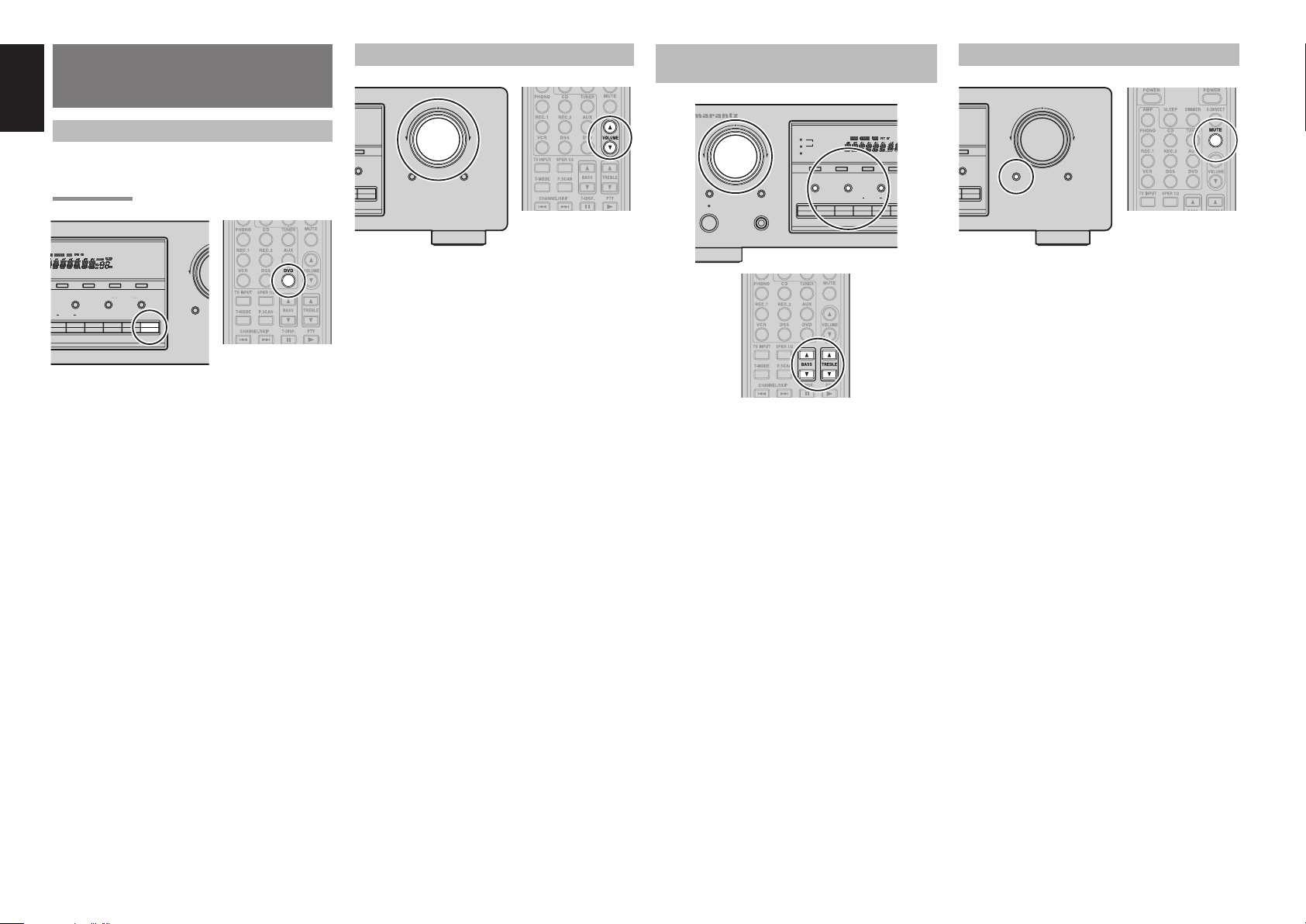
SELECTING AN INPUT SOURCE
Before you can listen to any input media, you must
fi rst select the input source on the SR4021.
Example : DVD
ADJUSTING THE MAIN VOLUME
VOLUME
VOLUME
DOWN
DOWN
-MODE
2
MUTE
DVD
UP
UP
SOURCE
DIRECT
ADJUSTING THE TONE (BASS & TREBLE)
AND BALANCE CONTROL
RECEIVER SR4021
MULTI JOG
1
SPEAKERS
2
DISPLAY OFF
SLEEP DIMMER
STANDBY
POWER ON/OFF
CLEAR
MEMORY
BASS
BASS
TREBLE
TREBLE
PHONES
F/PBAND
BALANCE
BALANCE
RECORDER
21ATUNERCDPHONO
TEMPORARILY TURNING OFF THE SOUND
VOLUME
DOWN
-MODE
2
MUTEMUTE
DVD
UP
SOURCE
DIRECT
F/PBAND
BALANCE SPEAKERS
1
RECORDER
VCR
To select DVD, simply press the DVD button on the
front panel or press the DVD button on the remote.
After you have selected DVD, simply turn on the DVD
player and play the DVD.
DOWN
T-MODEAUTO TUNE
2
MUTE
DVDDSS21AUX
Adjust the volume to a comfortable level using
the VOLUME control knob on the front panel or
VOLUME 3 / 4 buttons on the remote.
To increase the volume, turn the VO LUME knob
clockwise or press VOLUME 3 b utton on the remote,
to decrease the volume, turn counterclockwise or
press VOLUME 4 button on the remote.
Note:
The volume can be adjusted within the range of – 80
to 0 dB, in steps of 1 dB.
During a listening session you may wish to adjust the
To temporarily silence all speaker outputs such as
when interrupted by a phone call, press the MUTE
button on the front panel or MUTE button on the
remote.
This will interrupt the output to all speakers and the
head-phone jack, but it will not affect any recording
or dubbing that may be in progress.
When the system is muted, the display will show
“MUTE ON” .
Press the MUTE button again to return to normal
operation.
Bass and Treble Control and Balance Control to suit
your listening tastes or room acoustics.
• The input name will appear in the display on the
front-panel.
• When an audio source is selected, the last video
input used remains routed to the VCR Output
Monitor Output. This permits simultaneous
and
viewing and listening to different sources.
• When a Video source is selected, the video
signal for that input will be routed to the Monitor
Output jack and will be viewable on a TV monitor
connected to the SR4021.
(Using the SR4021)
Press the BASS, TREBLE and BALANCE
1.
buttons on the front panel to select your desired
control.
Turn the MULTI JOG knob to adjust the
2.
control.
BALANCE: Turn the knob clockwise to decrease
volume of the left channel and turn the
knob counter clockwise to decrease
volume of the right channel.
TREBLE: Turning the knob clockwise enhance
the high frequency band, while turning
counterclockwise attenuates the high
frequency band.
BASS: Turning the knob clockwise enhance
the low frequency band, while turning
counterclockwise attenuates the low
frequency band.
(Using the remote control unit)
To adjust the bass effect, press BASS 3 or BASS 4
on the remote.
To adjust the treble effect, press TREBLE 3 or
TREBLE 4 on the remote.
Balance Control cannot be adjusted with the remote
control unit.
Note:
1212
When Source Direct mode is set, tone control is disable.
Page 17
USING THE SLEEP TIMER
E
T
P
N
RECORDING A SOURCE
In normal operation, the audio or video source
selected for listening through the SR4021 is sent to
the record outputs.
This means that any program you are watching
or listening to may be recorded simply by placing
machines connected to the outputs for RECORDER1
OUT, RECORDER2 OUT, and VCR OUT in the
record mode.
Recording the video from one source and the
audio from another
You can add the sound from one source to the
video of another source to make your own video
recordings.
Below is an example of recording the sound from
a compact disc player connected to CD IN and the
video from a video camera connected to AUX IN to
video cassette recorder connected to the VCR OUT
jack.
ENGLISH
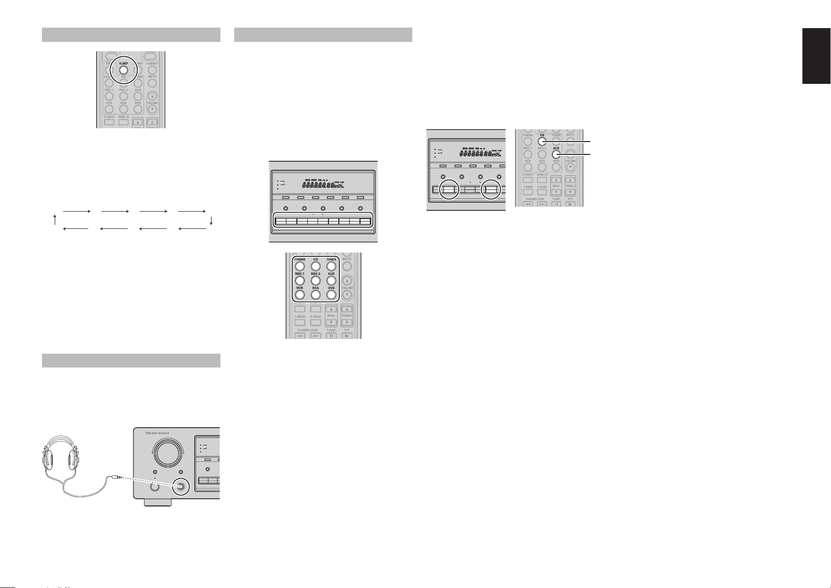
To program the SR4021 for automatic standby, press
the SLEEP button on the front panel or press the
SLEEP button on the remote.
Each press of the button will increase the time before
shut down in the following sequence.
OFF 10 20 30 40
90 80 70 60 50
The sleep time will be shown for a few seconds in the
display on the front panel, and it will count down until
the time has elapsed.
When the programmed sleep time has elapsed, the
unit will automatically turn off.
Note that the SLEEP indicator on the display will
illuminate when the Sleep function is programmed.
To ca ncel the Sleep function, press the SLEEP
button until the display shows “SLEEP OF (SLEEP
OFF)” and the SLEEP indicator will disappear.
LISTENING THROUGH HEADPHONES
This jack may be used to listen to the SR4021’s
output through a pair of headphones. Be certain that
the headphones have a standard 1/4" stereo phono
plug. (Note that the speakers will automatically be
turned off when the headphone jack is in use.)
RECEIVER SR4021
MULTI JOG
SLEEP DIMMER
STANDBY
POWER ON/OFF
1
SPEAKERS
2
DISPLAY OFF
CLEAR
BASS
PHONES
PHONES
CDPHONO
To record the input source signal you are currently
watching or listening to
1
SPEAKERS
2
DISPLAY OFF
BASS
Select the input source to record by pressing
1.
TREBLE
F/PBAND
BALANCE SPEAKERS
RECORDER
T-MODECLEAR AUTO TUNEMEMORY
2
1
VCR
DVDDSS21 AUXTUNERCDPHONO
the corresponding input selector button.
The input source is now selected and you may
watch or listen to it as desired.
The currently selected input source signal is
2.
output to the
RECORDER 1 OUT, RECORDER 2
OUT, and VCR OUT outputs for recording.
Start recording to the recording component as
3.
M
desired.
1
SPEAKERS
2
DISPLAY OFF
CLEAR
MEMORY
BASS
TREBLE
BALANCE S
RECORDER
21 AUXTUNERCDPHONO
AUTO TU
F/PBAND
1
VCR
1. Press the AUX input source button to set video
output.
Press the CD input source button to set audio
2.
output.
Now “CD” has been selected as the audio input
3.
source and “AUX” as the video input source.
Notes:
• If you change the input source during recording, you
will record the signals from the newly selected input
source.
• The setting of BALANCE, BASS, TREBLE,
VOLUME, MUTE does not affect the recorded
material.
• A given input source does not output on the same
OUT channel (For example, the signal input from
VCR IN is not output on VCR OUT).
• If you playback a video source that uses scrambled
or encoded signals to prevent it from being dubbed,
the picture itself may be disturbed due to those
signals.
2.
1.
1313
Page 18
ENGLISH
S
P
P
BASIC OPERATION
(TUNER)
LISTENING TO THE TUNER
The AM frequency scan increments are selectable.
The default is 9 kHz increments. If your country’s
standard is 10 kHz increments, press and hold the
BAND button on the front panel for 5 seconds or
more. The new scan increments will be stored.
Note:
The all Preset memory for the tuner will be cleared
clear by changing this setting.
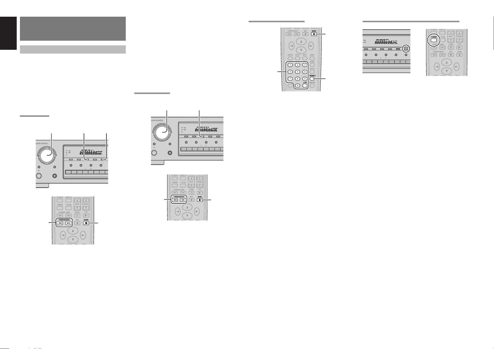
AUTO TUNING
1. 2.2.
RECEIVER SR4021
MULTI JOG
MULTI JOG
SLEEP DIMMER
STANDBY
OWER ON/OFF
1
SPEAKERS
2
DISPLAY OFF
CLEAR
BASS
PHONES
BAND AUTO TUNE
TREBLE
RECORDER
F/PBAND
AUTO TUNEMEMORY
BALANCE SPEAKERS
1
VCR
(Using the remote control unit)
To select the tuner and desired band (AM or
1.
FM), press BAND button.
Press the TUNE / SEARCH Q or R button
2.
more than 1 second on the remote.
Automatic searching begins then stops when a
3.
station is tuned in.
If tuning does not stop at the desired station, use
manual tuning.
MANUAL TUNING
2. 1.
RECEIVER SR4021
MULTI JOG
MULTI JOG
SLEEP DIMMER
STANDBY
OWER ON/OFF
1
SPEAKERS
2
DISPLAY OFF
CLEAR
BASS
PHONES
TREBLE
F/PBAND
BAND
BALANCE SPEAKERS
RECORDER
21AUXTUNERCDPHONO
AUTO TUNEMEMORY
1
D
VCR
DIRECT FREQUENCY CALL
1.
3.
2.
1. To select the tuner and desired band (AM or
FM), press the BAND button.
Press the F.DIRECT on the remote, display will
2.
show “F-DIR-IN”.
Input your desired station’s frequency with the
3.
numeric button on the remote.
E.g.) 98.1MHz : Press 9, 8, 1 and 0
The desired station will automatically be
4.
tuned.
(FM) TUNING MODE (AUTO STEREO OR MONO)
1
SPEAKERS
2
DISPLAY OFF
CLEAR
BASS
HONO
When FM has been selected, the current mode is
displayed when the T-MODE button on the front
panel or the T-MODE button on the remote control
unit is pressed once, and the screen changes when
the same button is pressed agein while the current
mode is displayed.
When “AUTO” mode is selected, “FM AUTO” appears
on the front display about 2 seconds. FM stations
that broadcast in stereo will be received in stereo and
the “STEREO” indicator lights up.
If the signal is weak, it may be impossible to tune into
the station in stereo. In such case, press the T-MODE
button on the front panel or press the T-MODE button
TREBLE
F/PBAND
BALANCE SPEAKERS
RECORDER
T-MODE
AUTO TUNEMEMORY
AUTO TUNE
2
1
DVDDSS21AUXTUNERCD
VCR
on the remote control unit. “FM MONO” appears on
DS21AUXTUNERCDPHONO
the front display about 2 seconds and the program is
received as the monaural mode.
To return to stereo, press the T-MODE button or T-
MODE button again. Some noise may be heard, but
the sound will not cut in and out as it would if stereo
was selected.
1.2.
1.2.
(Using the SR4021)
To select the tuner and desired ban d (AM
1.
or FM), press the BAND button on the front
(Using the SR4021)
1. To select the tuner and desired band (AM
panel
Turn the MULTI JOG knob on the front panel to
2.
select the desired station.
or FM), press the BAND button on the front
panel.
Press the AUTO TUNE button on the front
2.
panel, and turn the MULTI JOG knob to start
the Auto Tuning mode.
Automatic searching begins then stops when a
3.
station is tuned in.
(Using the remote control unit)
To select the tuner and desired band (AM or
1.
FM), press BAND button.
Press the TUNE / SEARCH Q or R button
2.
on the remote to tune in the desired station.
1414
Page 19
PRESET MEMORY
O
You can preset up to 30 AM/FM stations in any
order.
For each station, you can memorize the frequency
and reception mode if desired.
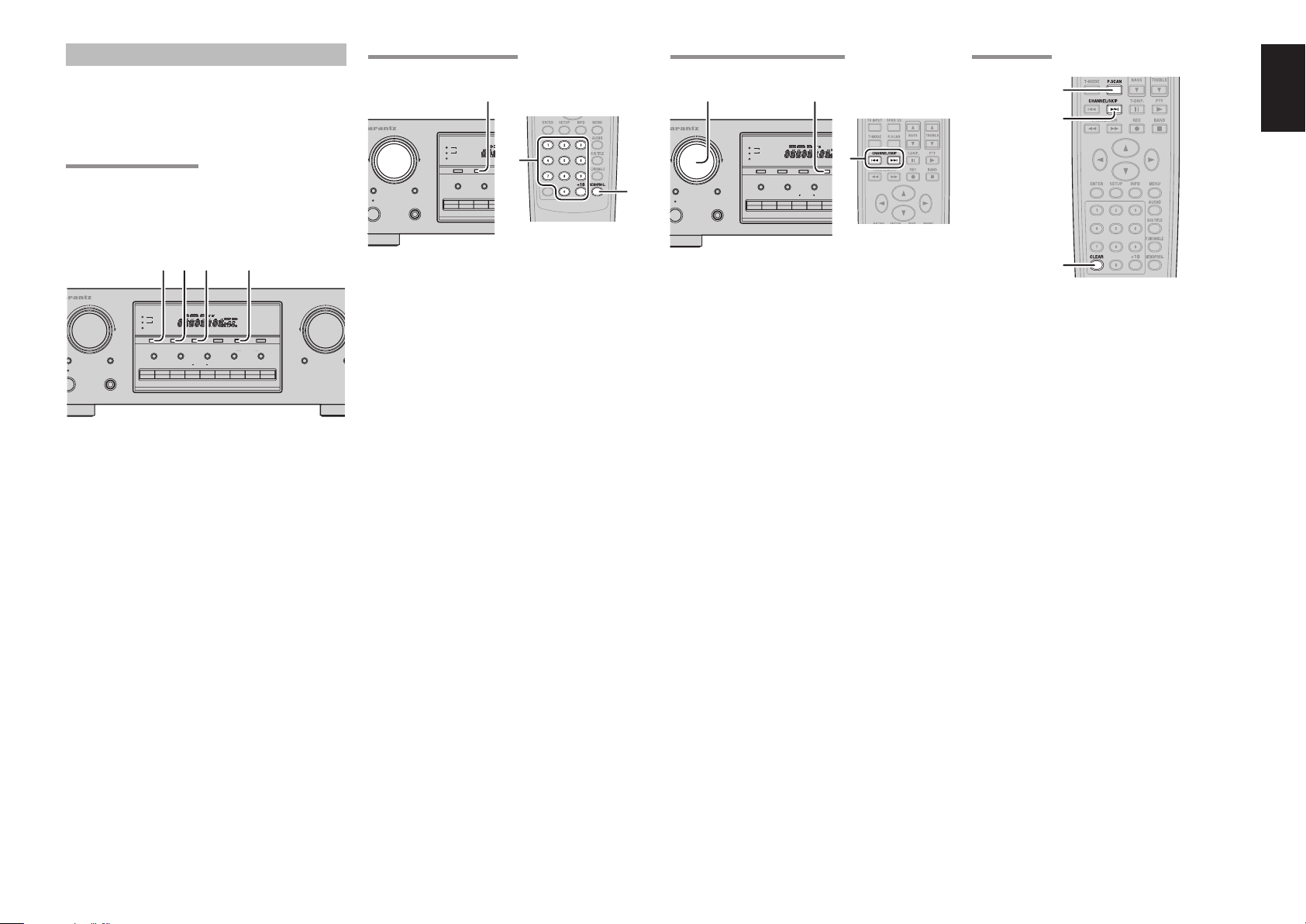
AUTO PRESET MEMORY
This function automatically scans the AM and FM
band and enters all stations with proper signal
strength into the memory.
MANUAL PRESET MEMORY
2. 4.
RECEIVER SR4021
MULTI JOG
MULTI JOG
SLEEP DIMMER
STANDBY
ER ON/OFF
1
SPEAKERS
2
DISPLAY OFF
CLEAR
MEMORY
MEMORY
BASS
PHONES
3.
TREBLE
TUNERCDPHONO
RECALLING A PRESET STATION
1. 1.
RECEIVER SR4021
MULTI JOG
MULTI JOG
SLEEP DIMMER
STANDBY
2.
PHONES
ER ON/OFF
PRESET SCAN
1.
3.
1
SPEAKERS
2
DISPLAY OFF
CLEAR
BASS
F/PBAND
MEMORY
F/P
1.
BALANCE
TREBLE
RECORDER
21AUXTUNERCDPHONO
ENGLISH
4. 3. 1. 3.
RECEIVER SR4021
1
SPEAKERS
2
DISPLAY OFF
CLEAR
EEP DIMMER
NDBY
ON/OFF
CLEAR
BASS
PHONES
MEMORY
TREBLE
F/PBAND
BALANCE SPEAKERS
RECORDER
T-MODE
AUTO TUNEMEMORY
AUTO TUNEBAN D
2
1
VCR
DVDDSS21AUXTUNERCDPHONO
1. Select the FM band with the BAND button on
the front panel.
Tune in the lowest receivable frequency.
2.
Press and hold down the MEMORY button
3.
and AUTO TUNE button simutaneously, auto
presetting will start.
Each time the tuner fi nds a station, the scanning
4.
will pause and memory.
Operation stops automatically when all 30
5.
preset memory positions are fi lled or when auto
scanning attains the highest end of all bands.
To stop the auto preset function at anytime,
press the CLEAR button.
Note:
If Auto Presetting is interrupted by pressing the
CLEAR button, the memory which has already been
set is kept still.
VOLUMEMULTI JOG
DOWN
MUTE
(Using the SR4021)
Tune into the desired radio station. (See the
1.
“MANUAL TUNING” or “AUTO TUNING”).
Press the MEMORY button on the front panel.
2.
S
DI
“MEMORY” indicator blinks in the display.
Select the preset number by turning the MULTI
3.
JOG knob while it is still blinking. (approx. 5
second)
Press the MEMORY button again to enter.
4.
“MEMORY” indicator stops blinking and goes
out.
The station is now stored in the specified
preset memory location.
(Using the remote control unit)
Tune into the desired radio station. (See the
1.
“MANUAL TUNING” or “AUTO TUNING”).
Press the MEMO / PROG button on the remote
2.
control unit. “MEMORY” indicator blinks in the
display.
Enter the desired preset number by pressing
3.
the numeric keypads.
Notes:
• When entering a single digit number (2 for example),
either input “02” or just input “2” and wait for a few
seconds.
• If a preset number already used is selected ,the
currently tuned station is stored with the preset
number and the formerly stored station with the
number is erased without any warning.
(Using the SR4021)
Press the F/P button to show the preset station
1.
on the display. Select the desired preset station
by turning the MULTI JOG knob on the front
panel.
(Using the remote control unit)
Press the CHANNEL/SKIP S or T button
1.
to select the desired preset station, or input
the desired preset channel with the numeric
keypad on the remote control unit.
3.
(Using the remote control unit)
Press the P.SCAN on the remote control unit.
1.
The preset station with the lowest preset
number is recalled fi rst.
Preset stations are recalled in sequence (No. 1
2.
→ No. 2 → etc.) for 5 seconds each.
No stored preset number will be skipped.
You can fast forward through the preset
3.
stations by pressing the CHANNEL / SKIP
T continuously.
When the desired preset station is received,
cancel the preset scan operation by pressing
the CLEAR or P.SCAN.
1515
Page 20
ENGLISH
CLEARING STORED PRESET STATIONS
You can remove preset stations from the memory
using the following procedure.
3. 2.
ER SR4021
1
SPEAKERS
2
DISPLAY OFF
CLEAR
CLEAR
BASS
DIMMER
PHONES
1. Recall the preset number to be cleared with the
method described in “RECALLING A PRESET
STATION”.
Press the MEMORY button on the front panel
2.
or MEMO/PROG. button on the remote control
unit.
“MEMORY” indicator blinks in the display for
3.
5 seconds. While blinking, press the CLEAR
button on the front panel or press the CLEAR
button on the remote control unit.
“CLEAR” appears on the display to indicate
4.
that the specified preset number has been
cleared.
F/PBAND
MEMORY
MEMORY
BALANCE
TREBLE
RECORDER
3. 2.
21AUXTUNERCDPHONO
NAME INPUT OF THE PRESET STATION
This function allows the name of each preset channel
to be entered using alphanumeric characters.
Before inputting names, you need to store preset
stations with the preset memory operation.
4. 3. 2. 5. 6.
RECEIVER SR4021
MULTI JOG
MULTI JOG
SLEEP DIMMER
STANDBY
OWER ON/OFF
Recall the desired preset number with the
1.
method described in “RECALLING A PRESET
STATION”.
Press the MEMORY button on the front panel
2.
or press the MEMO / PROG. button on the
remote for more than 3 seconds.
The left most column of the station name
3.
indicator fl ashes, indicating the character entry
ready status.
When turn the MULTI JOG knob on the front
4.
panel, alphabetic and numeric characters will
be displayed in the following order:
A → B → C ...Z → 1 → 2 → 3..... 0 → – → + →
/ → (Blank) → A
Clockwise →
← Counter clockwise
Numeric keypad Display
1
SPEAKERS
2
DISPLAY OFF
CLEAR
CLEAR
MEMORY
MEMORY
BASS
TREBLE
4.
PHONES
1
2
3
4
5
6
7
8
9
0
TUNERCDPHONO
A
→ B → C → 1 → A
D
→ E → F → 2 → D
→ H → I → 3 → G
G
J
→ K → L → 4 → J
M
→ N → O → 5 → M
→ Q → R → 6 → P
P
S
→ T → U → 7 → S
V
→ W → X → 8 → V
→ Z → space → 9 → Y
Y
–
→ + → / → 0
2.
5.
5. After selecting the fi rst character to be entered,
press the MEMORY button on the front panel
or press MEMO/PROG. button on the remote.
The entry in this column is fi xed and the next
column starts to flash. Fill the next column
using the same method.
Note:
Unused columns should be fi lled by entering blanks.
To save the name, press the MEMORY button
6.
for more than 3 seconds to confi rm the entry.
RDS OPERATION
Now in use in many countries, RDS (Radio Data
System) is a description of the station’s programming
hidden space in the FM signal.
Your new receiver is equipped with RDS to assist
in the selection of FM stations using station and
network names, rather than broadcast frequencies.
Additional RDS functions include the ability to search
for programme types.
RADIO TEXT
Some RDS stations broadcast RADIO TEXT, which is
additional information on the station and programme
being broadcast.
RADIO TEXT information appears as ‘running’ text
in the display. RADIO TEXT is transmitted character
by the radio station. As a result of that it may take
some time until the entire text has been completely
received.
RDS DISPLAY
When a receiver is tuned to an FM station that is
transmitting RDS data, the Front Panel Information
Display will automatically show the station name or
RADIO TEXT in place of the typical display of the
station’s broadcast frequency.
To change the display, press the T-DISP button on
the remote.
PROGRAMME TYPE (PTY) DISPLAY
The RDS system categorizes programmes according
to their genre into different programme type (PTY)
groups. To display the programme type information
of the current station, press the PTY button in the
TUNER MODE on the remote.
PTY AUTO SEARCH
Your receiver is equipped to automatically search for
stations transmitting any of 29 different programme
types. To search for a PTY, follow these procedures:
1. 3. 4.2.
Press the PTY button in the TUNER MODE on
1.
the remote. The current station’s PTY will be
displayed, or the currently selected PTY group
will be displayed in blinking if no station or RDS
data is present.
To cha nge to a new PTY type, press the
2.
CHANNEL/SKIP S or T button on the
remote until the desired PTY is shown in the
display.
1616
PS (
Program Service Name
RT (
RADIO TEXT
) Frequency
)
Page 21
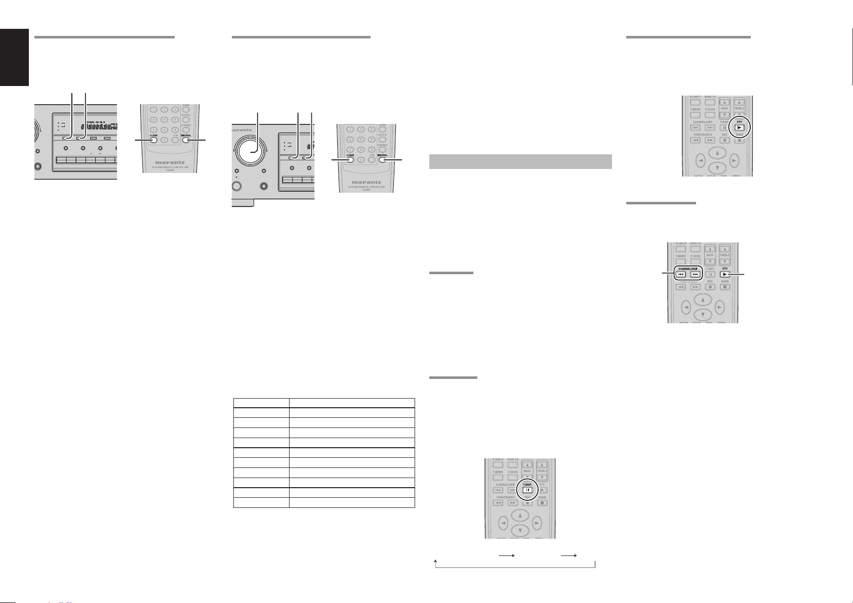
3. Once the desired PTY group or type has
been selected, press the PTY button while
the display blink (approx. 5 seconds). The
PTY Auto search will start, and the tuner will
pause at each station broadcasting RDS PTY
information corresponding to the selected
choice.
To advance to the next RDS station with the
4.
desired PTY, press the PTY button again within
5 seconds.
NUMBER DISPLAY PROGRAMME TYPE
1 POP Pop Music
2 ROCK Rock Music
3 MOR M. O. R. Music
4 LIGHT Light classical
5 CLASSIC Serious classical
6 NEWS News
7 AFFAIR Current Affairs
8 INFO Information
9 SPORT Sport
10 EDUCATE Education
11 DRAMA Drama
12 CULTURE Culture
13 SCIENCE Science
14 OTHERS Varied
15 OTHER Other Music
16 WEATHER Weather
17 FINANCE Finance
18 CHILDREN Children’s programmes
19 SOCIAL Social Affairs
20 RELIGION Religion
21 PHONE IN Phone In
22 TRAVEL Travel
23 HOBBIES Hobbies
24 JAZZ Jazz Music
25 COUNTRY Country Music
26 NATION National Music
27 OLDIES Oldies Music
28 FOLK Folk Music
29 DOCUMENT Documentary
TROUBLESHOOTING
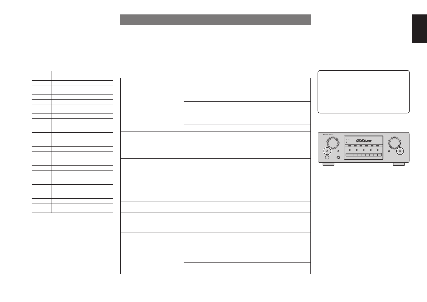
In case of trouble, check the following before calling for service:
1. Are the connections made properly ?
2. Are you operating the unit properly following the user’s guide ?
3. Are the power amplifi ers and speaker working properly ?
If the unit does not operate properly, check items shown in the following table.
If your trouble cannot be recovered with the remedy actions listed in the following table, malfunction of the
internal circuitry is suspected; immediately unplug the power cable and contact your dealer, nearest Marantz
authorized dealer or the Marantz Service Center in your country.
SYMPTOM CAUSE REMEDY
SR4021 cannot be turned up. The power plug is not connected. Connect the power plug to the outlet.
No sound and picture are output even
when power is on.
No speaker output. The headphones are connected to the
Incorrect Audio or Video for selected
source.
Sound is only heard from one of front
speakers
FM or AM reception fails. Antenna connection is incomplete. Correctly connect the indoor FM and
Noise is heard during AM reception. Reception is affected by other electrical
Noise is heard during FM reception. The radio waves from the broadcasting
Cannot get programmed station when
the PRESET button is pressed.
Control with the remote control unit fails. Batteries are consumed. Replace all the batteries with new ones.
Mute is on. Cancel mute using the remote control
unit.
The input cable is not connected
correctly.
The master volume control is turned all
See the connection diagram and connect
the cables correctly.
Adjust the master volume.
the way down.
The function selector position is wrong. Select correct position.
Disconnect the headphones. (Speakers
headphone jack.
will not output sound when headphones
are connected.)
Input cable connected incorrectly. Connect the cable correctly by referring
to the connection diagram.
The BALANCE control is set to one end.
One of the connection cords is
disconnected.
Adjust BALANCE control.
Connect the right and left connection
cords securely.
AM antennas to FM and AM antenna
outlets.
Try changing location where the AM
fi elds.
indoor antenna is set up.
Install an FM outdoor antenna.
station are weak.
Preset data has been erased. Disconnecting power plug for long
periods of time will erase preset data.
If that happens, input the preset data
again.
Remote controller’s function-key setting
is wrong.
The distance between this SR4021 and
Select different position from which
equipment will be controlled.
Move closer to this SR4021.
the remote commander is too far.
Something is blocking SR4021 and the
Remove offending object.
remote commander.
GENERAL MALFUNCTION
If the equipment malfunctions, this may be because
an electrostatic discharge or AC line interference has
corrupted the information in the equipment memory
circuits. Therefore:
- disconnect the plug from the AC line supply
- after waiting at least three minutes, reconnect
the pl
ug to the AC line supply
- re-attempt to operate the equipment
Memory backup
• In case a power outage occurs or the power
cord is accidentally unplugged, the SR4021
is equipped with a backup function to prevent
memory data such as the preset memory
from being erased. This function provides
approximately one week of memory storage.
HOW TO RESET THE UNIT
RECEIVER SR4021
MULTI JOG
SLEEP DIMMER
SLEEP
STANDBY
POWER ON/OFF
1
SPEAKERS
2
DISPLAY OFF
CLEAR
BASS
PHONES
TREBLE
BALANCE SPEAKERS
RECORDER
F/PBAND
T-MODE
AUTO TUNEMEMORY
2
1
VCR
VOLUME
UP
DOWN
SOURCE
SOURCE
MUTE
DIRECT
DVDDSS21AUXTUNERCDPHONO
DIRECT
Should the operation or display seem to be abnormal,
reset the unit with the following procedure.
The SR4021 is turned on, press and hold the SLEEP
and SOURCE DIRECT buttons simultaneously for 3
seconds or more.
Remember that the procedure will reset the settings
of the function selector, TUNER PRESET etc., to
their initial settings.
ENGLISH
1717
Page 22
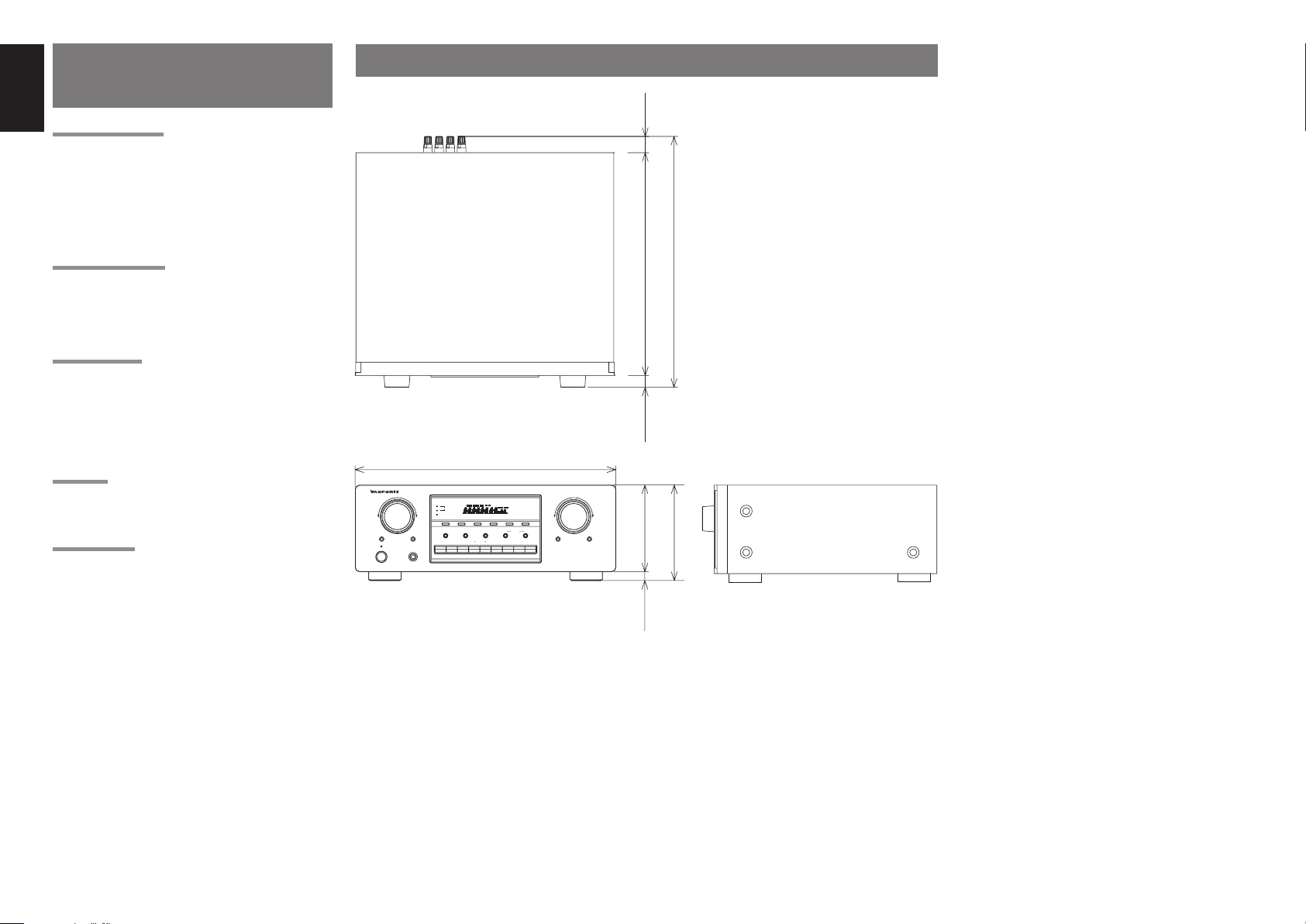
ENGLISH
RECORDER
F/P
BAND
BALANCE
SPEAKERS
SOURCE
DIRECT
SPEAKERS
DISPLAY OFF
BASS
TREBLE
VCR
T-MODE
CLEAR
AUTO TUNE
MEMORY
DVD
DSS
AUX
TUNERCDCD
PHONO
DOWN
VOLUME
MULTI JOG
UP
RECEIVER SR4021
SLEEP
DIMMER
MUTE
STANDBY
PHONES
POWER ON/OFF
TECHNICAL
SPECIFICATIONS
DIMENSIONS
FM TUNER SECTION
Frequency Range ................................87.5 – 108.0 MHz
Usable Sensitivity .............................IHF 2.0 µV/17.3 dBf
Signal to Noise Ratio ................... Mono/Stereo 70/65 dB
Distortion .......................................Mono/Stereo 0.2/0.3%
Stereo Separation ......................................... 1 kHz 40 dB
A.C.S ......................................................±300 kHz 50 dB
Image Rejection .........................................98 MHz 70 dB
Tuner Output Level ............... 1 kHz, 40 kHz Dev 500 mV
AM TUNER SECTION
Frequency Range ................................... 531 – 1602 kHz
Usable Sensitivity ........................................ Loop 400 µV
Signal to Noise Ratio ..............................................50 dB
Distortion ....................................400 Hz, 30% Mod. 1.0%
Selectivity ....................................................±9 kHz 40 dB
AUDIO SECTION
Rated Power ................ 40 Hz – 20 kHz 8 ohms 80 W/Ch
40 Hz – 20 kHz 6 ohms 100 W/Ch
THD .................................40 Hz – 20 kHz 8 ohms 0.08%
Input Sensitivity/Impedance
Linear .......................................... 200 mV/47 kohms
Signal to Noise Ratio (IHF A)
Linear ..............................................................95 dB
GENERAL
Power Requirement ................................AC 230 V 50 Hz
Power Consumption .............................................. 220 W
Weight ................................................................. 11.7 Kg
ACCESSORIES
Remote Control Unit RC4021SR ................................... 1
AAA-size batteries ........................................................ 2
FM Antenna ................................................................... 1
AM Loop Antenna .......................................................... 1
AC Power Cord .............................................................. 1
Specifi cations subject to change without prior notice.
25 mm
387.5 mm
342.5 mm
20 mm
440 mm
RECEIVER SR4021
MULTI JOG
1
SPEAKERS
2
DISPLAY OFF
CLEAR
SLEEP
STANDBY
POWER ON/OFF
BASS
DIMMER
PHONO
PHONES
F/P
BAND
T-MODE
MEMORY
AUTO TUNE
BALANCE
TREBLE
TUNER
SPEAKERS
1
RECORDER
VCR
DSS
21 AUX
VOLUME
DOWN
2
DVD
UP
SOURCE
DIRECT
MUTE
162.3 mm
16.3 mm 146 mm
1818
Page 23

www.marantz.com
You can find your nearest authorized distributor or dealer on our website.
is a registered trademark.
05/2006 00M13CW851310 ecmf-ePrinted in China
 Loading...