

Page 1

Model SR-14mkII User Guide
AV Surround Receiver
R
Page 2

ENGLISH
ITALIANOI
WARRANTY
For warranty information, contact your local Marantz distributor.
RETAIN YOUR PURCHASE RECEIPT
Your purchase receipt is your permanent record of a valuab le purchase.
It should be kept in a safe place to be referred to as necessary for
insurance purposes or when corresponding with Marantz.
IMPORTANT
When seeking warranty service, it is the responsibility of the consumer
to establish proof and date of purchase. Your purchase receipt or invoice is adequate for such proof.
FOR U.K. ONLY
This undertaking is in addition to a consumer's statutory rights and does
not affect those rights in any way.
FRANÇAIS
GARANTIE
Pour des informations sur la garantie, contacter le distributeur local
Marantz.
CONSERVER L'ATTESTATION D'ACHAT
L'attestation d'achat est la preuve permanente d'un achat de valeur. La
conserver en lieu sur pour s'y reporter aux fins d'obtention d'une
couverture d'assurance ou dans le cadre de correspondances avec
Marantz.
IMPORTANT
Pour l'obtention d'un service couvert par la garantie, il incombe au client d'établir la preuve de l'achat et d'en corroborer la date. Le reçu ou la
facture constituent des preuves suffisantes.
DEUTSCH
GARANTIE
Bei Garantiefragen wenden Sie sich bitte an Ihren Marantz-Händler.
HEBEN SIE IHRE QUITTING GUT AUF
Die Quittung dient Ihnen als bleibende Unterlage für Ihren wertvollen
Einkauf Das Aufbewahren der Quittung ist wichtig, da die darin
enthaltenen Angaben für Versicherungswecke oder bei Korrespondenz
mit Marantz angeführt werden müssen.
WICHTIG!
Bei Garantiefragen muß der Kunde eine Kaufunterlage mit Kaufdatum
vorlegen. Ihren Quittung oder Rechn ung ist als Unterlage ausreichend.
NEDERLANDS
Condizioni di garanzia
L'apparecchio e' garantito per 365 giorni dalla data di acquisto
comprovata da un documento attestante il nominativo del rivenditore e
la data di vendita. La garanzia sara' prestata con la sostituzione o
riparazione gratuita delle parti difettose.
Non sono coperti da garanzia difetti derivanti da uso improprio, errata
installazione, manutenzione effettuata da personale non autorizzato o,
comunque, da circostanze che non possano riferirsi a difetti di
tunzionamento dell'apparecchio. Sono inoltre esclusi dalla garanzia gli
interventi inerenti l'installazione e l'allacciamento agli impianti di
alimentazione.
Gli apparecchi verranno riparati presso i nostri Centri di Assistenza. Le
spese ed i rischi di trasporto sono a carico del cliente.
La casa costruttrice declina ogni responsabilita' per danni diretti o indiretti
provocati dalla inosservanza delle prescrizioni di installazione, uso e
manutenzione dettagliate nel presente manuale.
Per informazioni sull'abbonamento al Servizio Assistenza postgaranzia
e per conoscere l'indirizzo dei Centri Assistenza Marantz rivolgetevi al
nostro servizio consumatori (telefono 1678-20026 - numero verde).
PORTUGUÊS
GARANTIA
Para informações sobre a garantia, contactar o distribuidor Marantz
local.
GUARDAR O RECIBO DE COMPRA
O recibo é o registo permanente da compra que fez. De v e ser guardado
num local seguro, para ser apresentado em questões relacionadas com
o seguro ou para quando tiver de contactar a Marantz.
IMPORTANTE
Quando procurar assisténcia técnica ao abrigo da garantia, é da
responsabilidade do consumidor estabelecer a prova e data de compra.
O recibe é prova adequada.
SVENSKA
GARANTI
För information om garantin, kontakta Marantz lokalagent.
SPAR KVITTOT
Kvittot är ett inköpsbevis på en värdefull vara. Det skall förvaras säkert
och hänvisas till vid försäkringsfall eller vidkorrespondens mod Marantz.
VIKTIGT
Fö att garantin skall gälla är det kundens sak att framställa bevis och
datum om köpet. Kvitto eller faktura är tillräokligt bevis fö detta.
GARANTIE
Voor inlichtingen omtrent gar antie dient u zich tot uw plaatselijke Marantz.
UW KWITANTIE, KASSABON E.D. BEWAREN
Uw kwitantie, kassabon e.d. vormen uw bewijs van aankoop van een
waardevol artikel en dienen op een veilige plaats bewaard te worden
voor evt, verwijzing bijv, in verbend met verzekering of bij correspondentie
met Marantz.
BELANGRIJK
Bij een evt, beroep op de garantie is het de verantw oordelijkheid van de
consument een gedateerd bewijs van aankoop te tonen. Uw kassabon
of factuurzijn voldoende bewijs.
ESPAÑOL
GARANTIA
Para obtener información acerca de la garantia póngase en contacto
con su distribuidor Marantz.
GUARDE SU RECIBO DE COMPRA
Su recibo de compra es su prueba permanente de haber adquirido un
aparato de valor, Este recibo deberá guardarlo en un lugar seguro y
utilizarlo como referencia cuando tenga que hacer uso del seguro o se
ponga en contacto con Marantz.
IMPORTANTE
Cuando solicite el servicio otorgado por la garantia el usuario tiene la
responsabilidad de demonstrar cuá¥do efectuó la compra. En este caso ,
su recibo de compra será la prueba apropiada.
DANSK
GARANTI
Henvend dem til Deres MARANTZ-forhandler angående inrformation
om garantien.
GEM DERES KVITTERING
Deres købskvittering er Deres varige bevis på et dyrt køb. Den bør
gemmes godt og anvendes som bevis, hvis De vil tegne en forsikr ing,
eller hvis De kommunikerer med Marantz.
VIGTIGT
Det påhviler forbrugeren at skaffe bevis for købet og købsdatoen, hvis
han eller hun ønsker garantiservice. Deres købskvittering eller faktura
er et fuldgyldigt bevis herpå.
Page 3

CE MARKING
English
The SR-14mkII is in conformity with the EMC directive and low-voltage directive.
Français
Le SR-14mkII est conforme à la directive EMC et à la directive sur les basses tensions.
Deutsch
Das Modell SR-14mkII entspricht den EMC-Richtlinien und den Richtlinien für Niederspannungsgeräte.
Nederlands
De SR-14mkII voldoet aan de EMC eisen en de vereisten voor laag-voltage.
Español
El SR-14mkII está de acuerdo con las normas EMC y las relacionadas con baja tensión.
Italiano
Il SR-14mkII è conforme alle direttive CEE ed a quelle per i bassi voltaggi.
Português
O SR-14mkII conforma com as diretrizes EMC e de baixa voltagem.
Svenska
SR-14mkII är tillverkad i enlighet med EMC direktiven och direktiven för lågvoltsutrusning.
Dansk
Model SR-14mkII er i overensstemmelse med EMC-direktiveet og direktivet om lavspænding.
English
To ventilate the unit, do not install the unit in a rack or bookshelf, and
note the followings.
- Do not touch the top of the enclosure during operation.
- Do not block the openings in the enclosure during operation.
- Do not insert objects beneath the unit.
- Do not block the ventilation slots at the top of the unit.
Do not place anything about 1 meter above the top panel.
- Make a space of about 0.2 meter around the unit.
Français
Pour que l'appareil puisse être correctement ventilé, ne pas l'installer
dans un meuble ou une bibliothèque et respecter ce qui suit.
- Ne pas toucher le dessus du coffret.
- Ne pas obstruer les ouïes de ventilation du coffret pendant le
fonctionnement.
- Ne placer aucun objet sous l'appareil.
- Ne pas obstruer les ouães de ventilation du panneau supérieur. Ne
placer aucun objet à moins d'un mètre environ du panneau supérieur.
- Veiller à ce qu'aucun objet ne soit à moins de 0,2 mètre des côtés de
l'appareil.
Deutsch
Um eine einwandfreie Belüftung des Geräts zu gewährleisten, darf das
Gerät nicht in einem Gestell oder Bücherregal aufgestellt werden; die
folgenden Punkte sind besonders zu beachten:
- Während des Betriebs das Oberteil des Gehäuses nicht berühren.
- Während des Betriebs die Öffnungen im Gehäuse nicht blockieren.
- Keine Gegenstände in das Gerät einführen.
- Die Belüftungsschlitze an der Oberseite des Geräts dürfen nicht
blockiert werden. Darauf achten, daß über dem Gerät ein Freiraum
von mindestens 1 meter vorhanden ist.
- Auf allen Geräteseiten muß ein Zwischenraum von ungefähr 0,2 meter
vorhanden sein.
Italiano
Perch é l'unità possa essere sempre ben ventilata, non installarla in
scaffali o librerie e tenere presente quanto segue.
- Non toccare la parte superiore del rivestimento durante il
funzionamento.
- Non bloccare le aperture sul rivestimento durante il funzionamento.
- Non inserire oggetti al di sotto dell'unità.
- Non bloccare le fessure di ventilazione sopra l'unità.
Non posare nulla per circa un metro sopra il pannello superiore.
- Lasciare 0,2 metro liberi tutto intorno l'unità.
Português
Para ventilar o aparelho, não instalá-lo dentro duma estante ou algo
similar, e observar as seguintes recomendações:
- Não tocar a parte superior do aparelho durante a operação.
- Não bloquear as aberturas do aparelho durante a operação.
- Não insertar objectos debaixo do aparelho.
- Não bloquear as aberturas de ventilação na parte de cima do
aparelho. Deixar um espaço completamente livre de cerca de 1 metro
acima do painel superior.
- Deixar um espaço de cerca de 0,2 metro ao redor do aparelho.
Svenska
För att ventilera enheten, ställ den inte i ett ställ eller bokhylla och tänk
på följande.
- Vidrör inte ytterhöljets ovansida under pågående drift.
- Blockera inte öppningarna i ytterhöljet under pågående drift.
- Stick inte in föremål under enheten.
- Blockera inte ventialtionshålen ovanpå enheten.
Placera inte någonting närmare än 1 meter ovanför apparaten eller
enheten.
- Se till att det finns omkring 0,2 meter fri plats runt omkring enheten.
Nederlands
Installeer het toestel niet in een rek of boekenkast waar de ventilatie
mogelijk wordt gehinderd. Let tevens op de volgende punten:
- Raak de bovenkant van het toestel niet aan als het in gebruik is.
- Blokkeer de openingen van het toestel niet als het in gebruik is.
- Plaats geen onderwerpen onder het toestel.
- Blokkeer de ventilatie-openingen aan de bovenkant van het toestel
niet. Zorg dat er tenminste 1 meter vrije ruimte boven het toestel is.
- Zorg dat er 0,2 meter vrije ruimte rond het toestel is.
Español
Para ventilar la unidad no la instale en una estantería ni estante para
libros, y tenga en cuenta lo siguiente:
- No toque la parte superior de la caja durante el funcionamiento.
- No tape las ranuras en la caja durante el funcionamiento
- No ponga objetos debajo de la unidad.
- No tape las ranuras de ventilación de la parte superior de la unidad.
No ponga nada a menos de 1 metro por encima del panel superior.
- Deje un espacio de unos 0,2 metro alrededor de la unidad.
Dansk
Anbring ikke apparatet i et rack eller en boghylde, da dette kan bloke
luftcirkulationen omkring apparatet. Iagttag ligeledes følgende:
- Berør ikke oversiden af kabinettet under anvendelsen.
- Bloker ikke åbningerne i kabinettet under anvendelsen.
- Stik ikke genstande ind under apparatet.
- Bloker ikke ventilationsåbningerne ovenpå apparatet.
Anbring ikke noget nærmere end 1 m over apparatets overside,
- Sørg for, at der er et frit område på omkring 0,2 m omkring apparatet.
Page 4
AUDIO
AUDIO
REMOTE CONTROL
VIDEO
S - VIDEO
COMPONENT
VIDEO
ANTENNA
–
–
IN
DSS/VCR2
OUT
AUDIO
CD-R / MD
OUT
OUT
Cr
Cr
SPEAKER SYSTEMS 8 OHMS
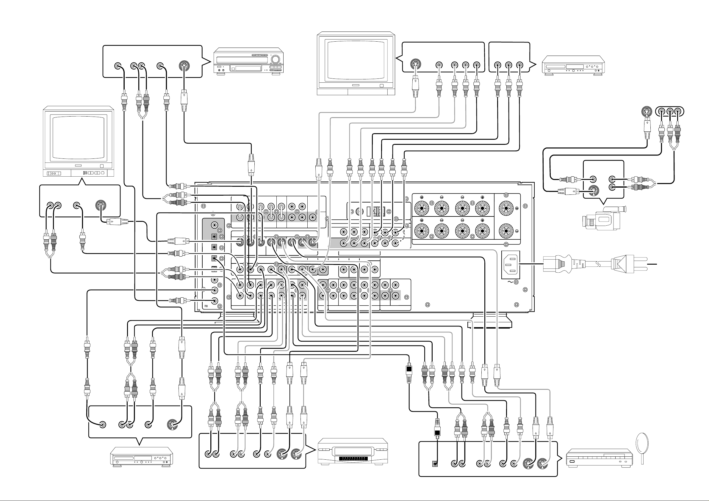
VIDEO SYSTEM CONNECTIONS FOR VIDEO COMPONENTS
Cr
Cr
Cb
Cb
MONITOR TV
AUDIO
OUT
LR
TV
VIDEO
OUT
OUT
S-VIDEO
OUT
RF
AUDIO
OUT
LR
VIDEO
OUT
S-VIDEO
OUT
COAX
DIG .1
DIG .2
DIG .3
DIG .4
DIG .5
DIG .6
RF IN
LD PLAYER
S-VIDEO
IN
VIDEO
IN
COMPONENT
VIDEO IN
Y Cr
Cb
COMPONENT
VIDEO OUT
Y Cr
Cb
DVD PLAYER,
SATELLITE TUNER or VCR
(FRONT AUX CONNECTIONS)
AUX INPUT
VIDEOS2-VIDEO L AUDIO R
OUT
AUDIO
OUT
L
R
To household
power outlet
VIDEO
FRONT
SURROUND
CENTER
–
OUT
OUT
(FRONT)
SURROUND BACK
DSS / VCR2 DSS / VCR2
S2 IN S2 OUT
OUT
–
–
IN
DSS/VCR2
OUT
WOOFER
SUB
MONI.
MAIN
PRE
OUT
AUDIO
MULTI
ROOM
IN
MULTI
ROOM
Y Cr
VCR1
IN
MONITOR
OUT
CENTER SURROUND
CD IN – TAPE – OUT
FM (75Ω)
COMPONENT
DIRECT IN
SUB
WOOFER
AUDIO
GND AM
VIDEO
Y Cr
RL
–
IN – CD-R / MD
OUT
REMOTE MULTI
REMOTE CONTROL
ANTENNA
DVD
IN
DSS
SPEAKER SYSTEMS 8 OHMS
/ VCR2
IN
IN
OUT
FRONT
OUT
OPT
OUT
IN
IN
IN
IN
IN
/
L
TV LD DVD MONI.VCR1 VCR1
S2 IN S2 IN S2 IN S2 IN
L
R
TV LD DVD IN
SURROUND
RL L
R
L R
SURROUNDFRONT
S - VIDEO
VIDEO
AUDIO
R L R
R L
–
VCR1
LR
LR
CENTER
VIDEO CAMERA
AC INLET
Connect the provided
detachable power cord
DIGITAL
OUT
AUDIO
OUT
VIDEO
OUT
LR
DVD PLAYER
S-VIDEO
OUT
AUDIO
OUT
LR
AUDIO
IN
LR
VIDEO
OUT IN
S-VIDEO
OUT IN
VCR
DIGITAL
OUT
AUDIO
OUT
LR
AUDIO
IN
LR
VIDEO
OUT IN
S-VIDEO
OUT IN
SATELLITE TUNER or VCR2
i
Page 5
AC INLET
AUDIO
REMOTE CONTROL
MULTITI
ROOM
S - VIDEO
COMPONENT
VIDEO
ANTENNA
DVD
IN
VCR1
OUT
IN
DSS/VCR2
OUT
DVD
MONI.
VCR1
VCR1
DSS / VCR2
DSS / VCR2
S2 IN
S2 IN
S2 IN
S2 IN
S2 IN
S2 OUT
AUDIO
IN
APE
OUT
IN
CD-R / MD
OUT
OUT
REMOTE
MULTITI
Cr
SPEAKER SYSTEMS 8 OHMS
FRONT
(FRONT)
SURROUND
WOOFER
SUB
MAIN
OUT
PRE
SURROUND
FRONT
SURROUND BACK
CENTER
OUT
OUT
MONI.
ROOM
MUL
TI
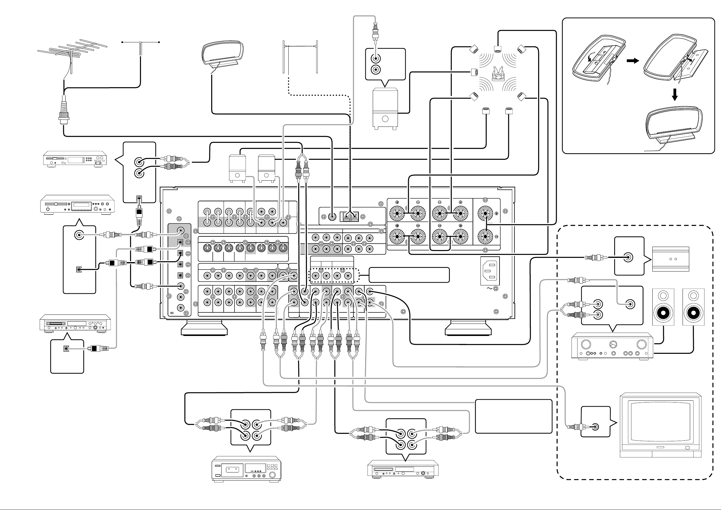
AUDIO SYSTEM CONNECTIONS FOR AUDIO COMPONENTS
FM EXTERNAL ANTENNA FM FEEDER ANTENNA
SUBWOOFER
AM EXTERNAL ANTENNAAM LOOP ANTENNA
AMPLIFIER
MA6100
SYSTEM
CENTER SPEAKER
Assemble the AM loop antenna as
shown in the figure before use
SPEAKER
¥ When using the FM antenna
attach to this apparatus
CD PLAYER
CD Recorder
DIGITAL
INPUT
DIGITAL
OUTPUT
MD PLAYER
OUTPUT
L
R
DIGITAL
OUTPUT
Suuround Back
AMPLIFIER
MA6100
COAX
OUT
OPT
OUT
DIG .1
IN
DIG .2
IN
DIG .3
IN
DIG .4
IN
DIG .5
IN
DIG .6
/
RF IN
L
FRONT
TVTVLDLDDVD
S2 IN
L
R
TVTVLDLDDVD
FRONT
CENTER
VCR1
OUT
–
OUT
(FRONT)
SURROUND BACK
DSS / VCR2
S2 IN
–
IN
DSS/VCR2
DSS / VCR2
OUT
SUB
WOOFER
MONI.
S2 OUT
MONI.
–
OUT
SURROUND
RL L
R
S2 IN
R L R
R L
L R
SURROUND
S - VIDEO
VCR1
S2 IN
S2 IN
VIDEO
–
IN
VCR1
AUDIO AUDIO
MAIN
PRE
OUT
MUL
ROOM
AUDIO
MUL
ROOM
IN
VCR1
MONITOR
OUT
TI
IN
CDCDIN
GND AM
FM (75Ω)
COMPONENT
DIRECT IN
SUB
WOOFER
–
IN
OUT
–
CD-R / MD
Y Cr
CENTER SURROUND
–
TAPE
VIDEO
Y Cr
RL
–
OUT
REMOTE
REMOTE CONTROL
NORMAL
INPUT
ANTENNA
DVD
DSS
/ VCR2
IN
IN
INVERT
OUTPUT
SPEAKER SYSTEMS 8 OHMS
SUBWOOFER
FRONT
SURROUND
Refer to OTHER CONNECTIONS
(Page iii)
IN
OUT
MUL
Left
Surround
Left
Surround
Back Left
SURROUND SPEAKER
LR
LR
CENTER
AC INLET
Right
Surround
Right
Surround
Back Right
MULTI
ROOM
INPUT
LINE IN RC IN
L
R
IR RECEIVER
MULTI ROOM SPEAKER
(L)
(R)
DIGITAL
INPUT
OUT IN
L
R
TAPE DECK
MAIN AMP
(For MULTI ROOM)
MONITOR TV for MULTI ROOM
To a component with REMOTE
(Marantz RC-5 D-BUS) jacks
Refer to OTHER CONNECTIONS
L
R
OUT IN
L
R
(Page iii)
L
R
VIDEO
IN
CD RECORDER/MD PLAYER
ii
MULTI ROOM
Page 6
AC INLET
COAX
OUT
OPT
OUT
DIG .1
DIG .2
MULTITI
ROOM
DIG .4
DIG .5
DIG .6
FM (75
GNDAMAM
RF IN
DVD
IN
–
VCR1
–
OUT
DVD
MONI.
VCR1
VCR1
DSS / VCR2
DSS / VCR2
S2 IN
S2 IN
S2 IN
S2 IN
S2 IN
S2 OUT
AUDIO
IN
–
APE
–
OUT
REMOTE
MULTITI
DSS
/ VCR2
IN
DVD
IN
FRONT
(SURR. BACK)
SURROUND
SPEAKER SYSTEMS 8 OHMS
DIG .3
FRONT
(FRONT)
SURROUND
WOOFER
SUB
MAIN
OUT
PRE
SURROUND
FRONT
SURROUND BACK
CENTER
OUT
OUT
MONI.
ROOM
MUL
TI
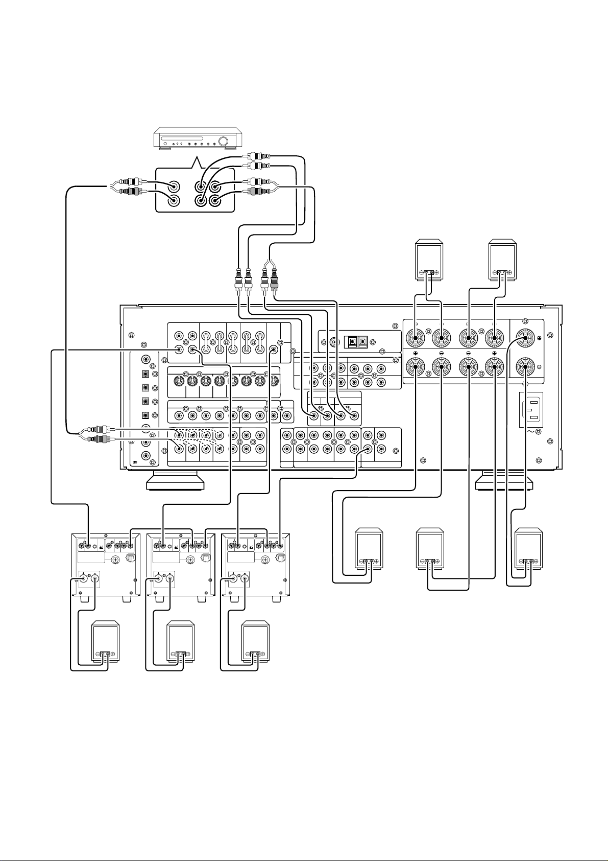
OTHER CONNECTIONS
(Connectio with external 3ch amplifiers for Front-L, Front-R and subwoofer)
OTHER MULTI CHANNEL PROCESSOR
L
C
R
SW
FRONT
RL L
COAX
OUT
OPT
OUT
DIG .1
IN
DIG .2
IN
DIG .3
INVERT
INPUT
BTL REMOTE CONT.EXT. CONT. IN
INPUT
OUTPUT
LEVEL
MASTERSLAVE
MIN MAX
IN
DIG .4
IN
DIG .5
IN
DIG .6
/
RF IN
INVERT
OUTPUT
IN
VIDEO/
SYSTEM OUT O UT
+5~13V DC
S
E
U
F
INPUT
L
TVTVLDLDDVD
S2 IN
L
R
TVTVLDLDDVD
INPUT
BTL REMOTE CONT.EXT. CONT. IN
LEVEL
MASTERSLAVE
MIN MAX
R
FRONT
S2 IN
VIDEO/
SYSTEM OUT O UT
+5~13V DC
S
E
U
F
LS
RS
SURROUND
L R
SURROUND
S - VIDEO
VCR1
S2 IN
S2 IN
VIDEO
IN
AUDIO AUDIO REMOTE CONTROL
IN
(FRONT)
R L R
R L
SURROUND BACK
CENTER
VCR1
DSS / VCR2
S2 IN
OUT
–
–
VCR1
OUT
IN – DSS/VCR2 – OUT
INVERT
INPUT
BTL REMOTE CONT.EXT. CONT. IN
INPUT
OUTPUT
LEVEL
MASTERSLAVE
MIN MAX
DSS / VCR2
OUT
VIDEO/
+5~13V DC
SYSTEM OUT O UT
S
E
U
F
WOOFER
S2 OUT
GND
FM (75
Ω
MAIN
IN
PRE
OUT
SUB
VCR1
IN
MONITOR
OUT
MONI.
MUL
TI
MONI.
ROOM
)
COMPONENT VIDEO
Y Cr
DIRECT IN
SUB
CENTER SURROUND
WOOFER
Y Cr
–
CDCDIN
–
TTAPE
OUT
IN – CD-R / MD – OUT
AUDIO
MUL
ROOM
Surround (R)
IN
ANTENNA
DVD
IN
DSS
/ VCR2
IN
RL
IN
OUT
REMOTE
MUL
speaker
Surround Back
(R) speaker
FRONT
(SURR. BACK)
SURROUND
SPEAKER SYSTEMS 8 OHMS
Surround Back
(L) speaker
LR
LR
CENTER
AC INLET
Surround (L)
speaker Center speaker
SPEAKER SYSTEM
MINIMUM 4 OHMS
SPEAKER SYSTEM
MINIMUM 4 OHMS
Front (L) speaker Front (R) speaker
SPEAKER SYSTEM
MINIMUM 4 OHMS
Subwoofer speaker
POWER AMPRIFIR
MA700
iii
Page 7
q
!5
@2
@0
rtyuio!0
we
!9
!1
!2
!7!8
!3 !4
!6
@1
@3
v
b
RC5000i
MUTE
z
CHANNEL
x
VOLUME
c
n
30
iv
Page 8

TABLE OF CONTENTS
INTRODUCTION.............................................................................................................................................................. 3
DESCRIPTION................................................................................................................................................................. 3
FEATURES ......................................................................................................................................................................4
FRONT PANEL FEATURES ............................................................................................................................................5
DISPLAY .......................................................................................................................................................................... 7
REAR PANEL CONNECTIONS.......................................................................................................................................8
REMOTE CONTROL UNIT RC5000I............................................................................................................................. 10
OPERATION OF REMOTE CONTROL UNIT......................................................................................................................................................... 12
SETUP ........................................................................................................................................................................... 13
ON SCREEN DISPLAY MENU SYSTEM ............................................................................................................................................................... 13
OSD MENU SYSTEM ............................................................................................................................................................................................ 14
SPEAKERS SETUP AND LEVELS SETUP ........................................................................................................................................................... 14
ON SCREEN DISPLAY INFOMATION ................................................................................................................................................................... 17
BASIC OPERATION ...................................................................................................................................................... 18
LISTENING TO THE TUNER.................................................................................................................................................................................. 18
RDS OPERATION (FOR S VERSION ONLY)......................................................................................................................................................... 19
PLAYBACK OPERATION ....................................................................................................................................................................................... 20
OTHER FUNCTIONS..................................................................................................................................................... 21
MULTI ROOM SELECTOR ..................................................................................................................................................................................... 21
TV AUTO ON/OFF FUNCTION .............................................................................................................................................................................. 21
SETTING THE SLEEP TIMER (ONLY REMOTE CONTROL UNIT)....................................................................................................................... 21
SURROUND MODES .................................................................................................................................................... 22
TROUBLESHOOTING................................................................................................................................................... 25
TECHNICAL SPECIFICATIONS ...................................................................................................................................27
1
Page 9

FOREWORD
ENGLISH
This section must be read before any connection is made to the
mains supply.
PRECAUTIONS
The following precautions should be taken when operating the
equipment.
WARNINGS
Do not expose the equipment to rain or moisture.
Do not remove the cover from the equipment.
Do not push anything inside the equipment through the
ventilation holes.
Do not handle the mains lead with wet hands.
EQUIPMENT MAINS WORKING SETTING
Your Marantz product has been prepared to comply with the
household power and safety requirements that exist in your area.
SR-14mkII can be powered by 230 V AC only.
IMPORTANT:
This apparatus is fitted with an approved moulded 13 Amp plug.
To change a fuse in this type of plug proceed as follows:
1. Remove fuse cover and fuse.
2. Fix new fuse which should be a BS1362 13A, A.S.T.A. or BSI
approved type.
3. Refit the fuse cover.
If the fitted plug is not suitable for your socket outlets, it should be cut
off and an appropriate plug fitted in its place.
If the mains plug contains a fuse, this should have a value of 13A. If a
plug without a fuse is used, the fuse at the distribution board should
not be greater than 5A.
Note:
The severed plug must be destroyed to avoid a possible shock
hazard should it be inserted into a 13A socket elsewhere.
How to connect a plug
The wires in the mains lead are coloured in accordance with the following code:
BLUE—“NEUTRAL” (“N”)
BROWN—“LIVE” (“L”)
1. The BLUE wire must be connected to the terminal which is marked
with the letter “N” or coloured BLACK.
2. The BROWN wire must be connected to the terminal which is marked
with the letter “L” or coloured RED.
3. Do not connect either wires to the earth terminal in the plug which is
marked by the letter “E” or by the safety earth symbol or coloured
green or green-and-yellow.
Before replacing the plug cover, make certain that the cord grip is
clamped over the sheath of the lead — not simply over the two wires.
COPYRIGHT
Recording and playback of any material may require consent. For
further information refer to the following:
— Copyright Act 1956
— Dramatic and Musical Performers Act 1958
— Performers Protection Acts 1963 and 1972
— any subsequent statutory enactments and orders
GENERAL PRECAUTIONS
When siting the equipment ensure that:
— the ventilation holes are not covered;
— air is allowed to circulate freely around the equipment
— it is on a vibration free-surface;
— it will not be exposed to interference from an external source;
— it will not be exposed to excessive heat, cold, moisture or dust;
— it will not be exposed to direct sunlight;
— it will not be exposed to electrostatic discharges
Never place heavy objects on the equipment.
If a foreign body or water does enter the equipment, contact your
nearest dealer or service centre.
Do not pull out the plug by pulling on the mains lead, hold the plug.
It is advisable when leaving the house, or during a thunderstorm, to
disconnect the equipment from the mains supply.
PRECAUTIONS IN CONNECTION
n Be sure to unplug the power cable from the AC outlet or turn
off the POWER/STANDBY switch before proceeding with any
connection.
n Connect one cable at a time observing the “input” and
“output”.
This will avoid any cross connection between channels and
signal inputs and outputs.
n Insert the plugs securely. Incomplete connection may result in
noise.
n Prior to connecting other audio and video equipment to the
SR-14mkII, please read their owner’s manuals.
INSTALLATION
If this unit or another electronic device incorporating a
microcomputer is used at the same time with the tuner or television,
picture disturbance or noise may occur. In such a case, install the
unit according to the following guide points.
n Separate the unit as far as possible from the tuner or
television.
n Place the antenna wire for the tuner or TV apart from the
power cable and audio and video connection cables of this
unit.
n Since the phenomenon is likely to occur when using an
indoor antenna and/or 300-ohm feeder wire, we
recommend using an outdoor antenna and 75-ohm coaxial
cable.
ABOUT THIS USER GUIDE
Refer to the figures on page 2 of this user guide. The numbers on the
figurescorrespond to those in the text. All references to the
connections and controls that are printed in BOLD type are as they
appear on the unit.
2
Page 10
INTRODUCTION
Thank you for purchasing the Marantz SR-14mkII THX/ DTS/Dolby
Digital Surround receiver. This remarkable component has been
engineered to provide you with many years of home theater
enjoyment. Please take a few minutes to read this manual thoroughly
before you connect and operate the SR-14mkII. As there are a
number of connection and configuration options, you are encouraged
to discuss your own particular home theater setup with your Marantz
A/V specialist dealer.
DESCRIPTION
THX® is an exclusive set of standards and technologies established
by the world-renowned film production company, Lucasfilm Ltd. THX
resulted from George Lucas’ desire to reproduce the movie
soundtrack as faithfully as possible both in the movie theater and in
the home theater.
THX engineers developed patented technologies to accurately
translate the sound from a movie theater environment into the home,
correcting the tonal and spatial errors that occur.
When the THX mode of the SR-14mkII is on, three distinct THX
technologies are automatically added:
Re-Equalization-restores the correct tonal balance for watching a
movie in a home environment.
These sounds are otherwise mixed to be brighter for a large movie
theater. Re-EQ compensates for this and prevents the soundtracks
from being overly bright and harsh when played in a home theater.
Timbre Matching-filters the information going to the surround
speakers so they more closely match the tonal characteristics of the
sound coming from the front speakers.
This ensures seamless panning between the front and surround
speakers.
Adaptive Decorrelation-slightly changes one surround channel’s time
and phase relationship with respect to the other surround channel.
This expands the listening position and creates with only two
surround speakers the same spacious surround experience as in a
movie theater with multiple surround speakers.
The Marantz SR-14mkII was required to pass a rigorous series of
quality and performance tests, in addition to incorporating the
technologies explained above, in order to be THX Ultra certified by
Lucasfilm Ltd.
THX Ultra requirements cover every aspect of performance including
pre-amplifier and power amplifier performance and operation, and
hundreds of other parameters in both the digital and analog domain.
Movies which have been encoded in Dolby Digital, DTS, Dolby Pro
Logic, stereo and Mono will all benefit from the THX mode when being
viewed.
The THX mode should only be activated when watching movies which
were originally produced for a movie theater environment.
THX need not be activated for music, movies made especially for TV,
or shows such as sports programming, talk shows, etc.
This is because they were originally mixed for a small room
environment.
“Lucasfilm®” and “THX®” are registered trademarks of Lucasfilm Ltd.
THX Surround EX - Dolby Digital Surround EX is a joint development
of Dolby Laboratories and the THX division of Lucasfilm Ltd.
In a movie theater, film soundtracks that have been encoded with
Dolby Digital Surround EX technology are able to reproduce an extra
channel which has been added during the mixing of the program.
This channel, called Surround Back, places sounds behind the
listener in addition to the currently available front left, front center,
front right, surround right, surround left and subwoofer channels.
This additional channel provides the opportunity for more detailed
imaging behind the listener and brings more depth, spacious
ambience and sound localization than ever before.
Movies that were created using the Dolby Digital Surround EX
technology when released into the home consumer market may
exhibit a Dolby Digital Surround EX logo on the packaging.
A list of movies created using this technology can be found on the
Dolby web site at
http ://www.dolby.com.
“SURROUND EX ™” is a trademark of Dolby Laboratories. Used
under authorization.
Dolby Digital lets you enjoy Digital TV, Digital Satellite as well as DVD,
LD software in digital surround, which is the next step above Dolby
Pro Logic.
In comparison with Dolby Pro Logic, Dolby Digital can provide
separate left surround and right surround channels, for more precise
localization of sounds and a more convincing, realistic ambience.
And, with Dolby Digital, all five main channels can be full ranged and
a subwoofer can be added to each channel , if desired.
By providing up to 5.1channels of digital audio independently, Dolby
Digital lets you enjoy better sound quality and more powerful
presence than conventional Dolby Surround.
“Dolby”, “AC-3”, “Pro Logic” and the double-D symbol are
trademarks of Dolby Laboratories.
DTS was introduced in 1994 to provide 5.1 channels of discrete
digital audio into home theater systems.
DTS brings you premium quality discrete multi-channel digital sound
to both movies and music.
DTS is a multi-channel sound system designed to create full range
digital sound reproduction.
The no compromise DTS digital process sets the standard of quality
for cinema sound by delivering an exact copy
of the studio master recordings to neighborhood and home theaters.
Now, every moviegoer can hear the sound exactly as the moviemaker
intended.
DTS can be enjoyed in the home for either movies or music on of
DVD’s, LD’s, and CD’s.
“DTS” and “DTS Digital Surround” are trademarks of Digital Theater
Systems, Inc.
ENGLISH
3
Page 11

ENGLISH
HDCD® (High Definition Compatible Digital ®) is a patented process
for delivering on Compact Disc the full richness and details of the
original microphone feed.
HDCD encoded CDs sound better because they are encoded with 20bits of real musical information as compared to 16-bits for all other
CDs.
HDCD overcomes the limitation of the 16-bit CD format by using a
sophisticated system to encode the additional four bits onto the CD
while remaining completely compatible with the CD format.
When listening to HDCD recordings, you hear more dynamic range,
a focused 3-D sound stage, and extremely natural vocal and musical
timbre. With HDCD, you get the body, depth and emotion of the
original performance not a flat, digital imitation.
®, HDCD®, High Definition Compatible Digital ® and Pacific
Microsonics™ are either registered trademarks or trademarks of
Pacific Microsonics, Inc. in the United States and/or other countries.
HDCD system manufactured under license from Pacific Microsonics,
Inc. This product is covered by one or more of the following: In the
USA: 5,479,168, 5,638,074, 5,640,161, 5,808,574, 5,838,274,
5,854,600, 5,864,311, 5,872,531, and in Australia: 669114. Other
patents pending.
®
FEATURES
• THX SURROUND EX decoding to reproduce an extra channel
which has been added during the mixing of the program.
• Dolby Digital and DTS surround sound decoding, plus THX Cinema
processing, Dolby Pro Logic decoding and a variety of additional
surround modes.
• HDCD decoding capability to deliver the full sonic benefits of
HDCD-encoded CDs from a standard non-HDCD CD player when
connected to the SR-14mkII via the player ’s digital output.
• 96 kHz/ 24 bit decoding for highest possible fidelity and
bandwidth, and high-resolution playback of 96 kHz/ 24 bit PCM
audio sources.
• Poly Silicon high resolution 8 ch Volume control
• Selectable main input terminals (L/R or Surr.Back L/R)
• 140 watts to each of the five main channels; the power amp section
features an advanced, premium high- storage power supply
capacitors, and fully discrete output stages housed in cast
aluminum heat sinks .
• High Definition Amplifier Module (HDAM) discrete pre-amp output
stages.
• 7.1 channel pre-amp outputs for connection to external
components such as a subwoofer and external power amplifiers.
• Six-channel direct inputs accommodate future surround sound
formats or an external digital decoder.
• Six Digital inputs, for connection to other sources, such as DVD,
DSS, CD or LD.
• Two Digital outputs for connection to CD-R or MD.
• High-quality AM/FM tuner with 50 station presets.
• Source Direct switch bypasses, tone controls and bass
management for purest audio quality.
• Three sets of Y/Pr/Pb component video inputs and component
video outputs provide unsurpassed video quality and switching
flexibility from component video sources.
• On- Screen- Display with both Composite and “S” video.
• Front panel A/V inputs, with S-video .
• Easy to use on-screen menu.
• Multi-room capability offers independent control of a second room
audio and video system.
• Supplied with RC5000i programmable learning remote control.
4
Page 12

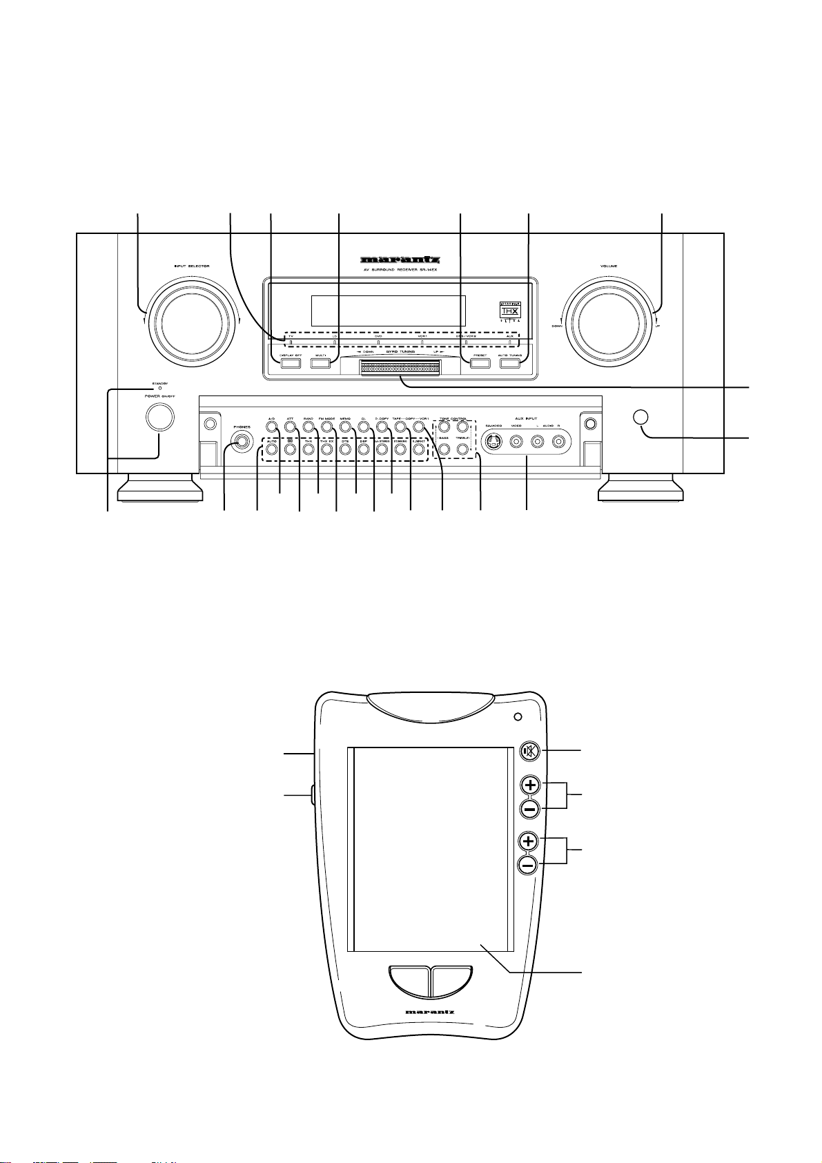
FRONT PANEL FEATURES
r A/D (Analog/Digital) SELECTOR
(SEE PAGE iv)
q POWER switch and STANDBY indicator
You can turn on and off the unit’s power using the front panel power
switch.
However, if you turn the unit off with the front panel switch, the unit
goes completely off rather than to the “standby mode” (Red LED
indicator light glows in the standby mode).
The unit cannot be turned on with the remote control when it is not in
the standby mode. When the red LED is on, the unit can be turned on
via the remote control or by pressing any input selector button on the
front panel.
w PHONES jack for stereo headphones
This jack may be used to listen to the SR-14mkII’s output through a
pair of headphones. Be certain that the headphones have a
standard 1 /4" stereo phone plug. Note that the main room speakers
will automatically be turned off when the headphone jack is in use.
Notes:
• When using headphones, the surround mode will automatically
change to STEREO .
• The surround mode returns to the previous setting as soon as the
plug is removed from the jack.
e Surround MODE buttons
(AUTO, 2 (DOLBY), THX, THX-EX, DTS, DSP, 5CH
STEREO, STEREO/MONO , S-DIRECT )
Press the desired button to select surround mode.
AUTO :
The receiver determines whether the digital input signal is Dolby
Digital, PCM-audio , HDCD or DTS.
2 :
This mode is used with source materials encoded in Dolby Digital
and Dolby Surround.
THX (THX Cinema or THX EX) :
THX Cinema mode applies additional processing to Dolby Digital,
DTS, and Dolby Pro Logic multi-channel surround sources. Use the
THX Cinema mode for all movies on disc, tape or broadcast.
THX-EX :
THX Surround EX will operate for any 5. 1 channel source whenever
THX is activated.
DTS (Cinema or Music) :
This mode is for DTS encoded source materials such as LASER
DISC, CD, and DVD. Press this button to select DTS-Cinema
mode. Press it again to select DTS-Music mode.
DSP (HALL, MATRIX, MOVIE):
These modes apply additional surround processing to each source
for theater, concert hall and stadium like atmospheres. Choice
desired effect by pressing this button.
5CH STEREO:
This mode is used to create a wider, deeper and more natural
soundstage from two channel source material.
STEREO/ MONO :
STEREO mode bypasses all surround processing.
MONO mode is intended for use with old movies, televisions shows
and other programs that have a monaural sound track.
S. (Source) DIRECT :
In the source direct mode, the tone control circuit and bass
management configuration are bypassed for full range frequency
response and the purist audio reproduction.
(See page 22 for more information about surround modes.)
BUTTON
This is used to select between the analog and digital inputs.
Note:
• This button is not used for an input source that is not set to a
digital input in the system setup2/2.
t ATT (Attenuate) button
If the selected analog audio input signal is greater than the capable
level of internal processing, PEAK indicator will light. If this happens,
you should press the ATT button. “ATT” is displayed when this
function is activated.
The signal-input level is reduced by about the half. Attenuation will
not work with the output signal of “REC OUT” (TAPE, CD-R/MD, VCR1
and DSS/VCR2 output). This function is memorized for each
individual input.
y BAND (Tuner Band Selector) button
Press this button to switch the tuner between AM or FM.
u FM MODE button
Press this button to select the auto stereo mode or mono mode when
the FM band is selected. The AUTO indicator lights in the auto stereo
mode.
i MEMO (memory) button
Press this button to enter the tuner preset memory numbers or station
names.
o CL (Clear) button
Press this button to cancel the station-memory setting mode or preset
scan tuning.
!0 D. (Digital) COPY button
Press this button for digital dubbing to a CD-R recorder or MD deck.
When this button is pressed, the digital source of the DIGITAL
OUTPUT is switched in the following sequence.
SOURCE DIG.1 DIG.2 DIG.3
(DIG.6) DIG.5 DIG.4OFF
!1 TAPE COPY button
Press this button for audio dubbing to a tape deck.
When this button is pressed, the source from the TAPE OUT is
switched in the following sequence.
SOURCE TUNER CD CD-R/MD
!2 VCR1 COPY button
Press this button for video and audio dubbing to a VCR1 deck.
When this button is pressed, the source from the VCR1 OUT is
switched in the following sequence.
SOURCE TV LD DVD DSS/VCR2 AUX
!3 BASS and TREBLE tone controls
These controls are used to boost or cut high and low frequencies.
TREBLE: Adjusts the tone of high-frequency sound.
BASS: Adjusts the tone of low-frequency sound.
press the up and down keys simultaneously to set . flat frequency
response
Notes:
• These buttons are disable in THX CINEMA mode,THX
SURROUND EX mode and Source Direct mode.
• Additionally these are not effective during playback of a HDCD
signal or 96k PCM audio signal.
5
ENGLISH
Page 13

ENGLISH
!4 AUX input jacks
These auxiliary video/audio input jacks accept the connection of a
camcorder, portable VCR, etc.
!5 INPUT SELECTOR knob
When this knob is turned, the input signal is switched in the following
sequence.
TUNER CD TAPE CD-R/MD TV
This knob can also be used to turn the unit’s power on when it is in the
standby mode.
DSS/VCR2 VCR1 DVD LDAUX
!6 VOLUME control knob
Adjusts the overall sound level. Turning the control clockwise
increases the sound level.
!7 AUTO TUNING button
When this button is pressed and the GYRO TUNING knob is turned
quickly, the frequency is scanned while turning the GYRO TUNING
knob. The Auto scan function starts when the GYRO TUNING knob is
stopped.
!8 PRESET BUTTON
Press this button to display the preset number. The preset number is
changed by turning the GYRO TUNING knob.
!9 MULTI (Multi Room) button
Press this button to activate the Multiroom system . “MULTI ” indicator
will light in the display.
@0 DISPLAY OFF button
When this button is pressed, the display is turned off and the display
off indicator lights up ( DISP ). Press this button again to turn the
display ON again.
@1 GYRO TUNING knob
Turn this knob to change the frequency or the preset number. The
station name can be selected with this knob.
@2 VIDEO SOURCE indicator
Indicates video source currently selected.
@3 INFRARED SENSOR window
This window receives infrared signals from the remote control unit.
6
Page 14

DISPLAY
(3)
ENGLISH
(4) (5) (8) (9) (12)
(2)
(1)
(1) Main Information Display
This display shows messages relating to the status, input source,
surround mode, tuner, volume level or other aspects of unit’s
operation.
(2) ENCODED SIGNAL indicators
2DIGITAL, 2SURROUND, dts, PCM, and HDCD
When the selected input is a digital source, one of these indicators
will light to display the specific type of signal in use.
(3) Analog Input Indicator
This indicator lights when an analog input source has been selected.
(4) TUNER’s indicators
STEREO :
This indicator illuminates when an FM station is being tuned in stereo.
AUTO :
This indicator illuminates when the tuner’s Auto mode is in use.
TUNED :
This indicator illuminates when a station is being received with
sufficient signal strength to provide acceptable listening quality.
(6) (7) (10)(11)
(10)Attenuation indicator
This indicator lights when the attenuation function is active.
(11)Display Off indicator
This indicator lights when the SR-14mkII is in the display off mode.
(12) ENCODED CHANNEL STATUS indicators
These indicators display the channels that are encoded with a digital
input signal. If the selected digital input signal is Dolby Digital 5.1ch
or DTS 5.1ch, “L”, “C”, “R”, “LS”, “RS” and “LFE” will light up.If the
digital input signal is 2 channel PCM-audio, “L” and “R” will be
displayed. If Dolby Digital 5.1ch signal with Surround EX flag comes
in, “L”, “C”, “R”, “LS”, “S” , “RS” and “LFE” will show.
(5) Multiroom Indicator
This indicator lights when the multiroom system is active.
(6) Sleep Indicator
This indicator lights when the Sleep function is in use.
(7) Copy Indicators
This indicator lights when VCR1 COPY, TAPE COPY, or DIGITAL
COPY system is active.
(8) Night Mode Indicator
This indicator lights when the SR-14mkII is in the Night mode, which
reduces the dynamic range of digital program material at low volume
levels.
(9) PEAK indicator
This indicator is a monitor for an analog audio input signal. If the
selected analog audio input signal is greater than the capable level of
internal processing, this will light. If this happens, you should press
the ATT button.
7
Page 15

ENGLISH
AC INLET
COAX
OUT
OPT
OUT
DIG .1
DIG .2
DIG .4
IN
DIG .5
IN
DIG .6
FM (75
GNDAMAM
RF IN
IN
DSS/VCR2
OUT
DSS / VCR2
DSS / VCR2
AUDIO
IN
CD-R / MD
OUT
DSS
/ VCR2
DVD
IN
FRONT
SURROUND
SPEAKER SYSTEMS 8 OHMS
DIG .3
REAR PANEL CONNECTIONS
All connections to the rear panel should be made with the entire
system powered off.
To avoid errors, it is advisable to connect one cable at a time between
the various components.
11
21 10
18 14 1 2 13 221716
COAX
DIG .1
DIG .2
DIG .3
DIG .4
DIG .5
DIG .6
OUT
OUT
RF IN
FRONT
SURROUND
RL L
R
L
OPT
IN
IN
IN
IN
IN
/
TV LD DVD MONI.VCR1 VCR1
S2 IN S2 IN S2 IN S2 IN
L
R
TV LD DVD IN – VCR1 – OUT
R L R
L R
R L
SURROUNDFRONT
S - VIDEO
VIDEO
AUDIO AUDIO REMOTE CONTROL
CENTER
OUT
(FRONT)
SURROUND BACK
DSS / VCR2
DSS / VCR2
S2 IN S2 OUT
OUT
–
–
IN
DSS/VCR2
OUT
WOOFER
MAIN
IN
PRE
OUT
SUB
MULTI
MONI.
ROOM
AUDIO
MULTI
ROOM
19 20 9 5 6 12 3 4 23 24 7 25
8
15
1 FM antenna terminal (75 ohms)
Connect an external FM antenna with a coaxial cable, or a cable
network FM source.
2 AM antenna and ground terminals
Connect the supplied AM loop antenna. Use the terminals marked
“AM” and “GND”. The supplied AM loop antenna will provide good
AM reception in most areas. Position the loop antenna until you hear
the best
3 Three analog audio inputs
CD, TAPE, and CD-R/MD :
Connect the audio outputs of your source components to the input
jacks on the receiver.
4 Two analog audio outputs for audio
source equipment
TAPE and CD-R/MD :
Connect each output to the audio inputs (REC in) of your recording
equipment.
5 Five analog audio inputs for video
source equipment
TV,LD,DVD, VCR1, and DSS/VCR2 :
Connect each input to the audio outputs of your video source
equipment.
6 Two analog audio outputs for video
source equipment
VCR1, and DSS/VCR2 :
Connect each output to the audio inputs (REC in) of your video
recording equipment.
Y Cr
VCR1
IN
MONITOR
OUT
CENTER SURROUND
CD IN – TAPE – OUT
FM (75
Ω
)
COMPONENT VIDEO
DIRECT IN
SUB
WOOFER
–
IN
CD-R / MD
LR
LR
CENTER
AC INLET
GND
Y Cr
RL
–
OUT
REMOTE MULTI
ANTENNA
DVD
IN
DSS
SPEAKER SYSTEMS 8 OHMS
/ VCR2
IN
IN
OUT
FRONT
SURROUND
7 6-Channel Inputs
If an external digital audio decoder is used, connect the outputs of
that decoder to these jacks. Note that front L&R channels are
common used in analog audio inputs, use the assigned input in OSD
setup menu system.
(See page 16 “System setup 1/2”.)
8 Five video inputs
TV,LD,DVD, VCR1, and DSS/VCR2 :
Connect each input to the video outputs of your video source
equipment.
9 Two video outputs
VCR1, and DSS/VCR2 :
Connect each output to the video input (REC in) of your video
recording equipment.
10 Five S-video inputs
TV,LD,DVD, VCR1,and DSS/VCR2 :
Connect each input to the S-video outputs of your video source
equipment.
11 Two S-video outputs
VCR1, and DSS/VCR2 :
Connect each output terminals to S-video input (REC in) of your video
recording equipment.
12 Monitor. (VIDEO/S-VIDEO) output jacks
Connect this jack to the composite or S-Video input of a TV monitor or
video projector to view the on-screen menus and the output of any
standard video source selected by the receiver’s video switcher.
8
Page 16

13 Three Component-video inputs
DVD,VCR1,DSS :
Connect the Y/Cr/Cb component video outputs of each your video
product to these jacks.
14 Component Video Outputs
Connect these outputs to the component video inputs of a video
projector or monitor. When a source connected to one of the three
Component Video Inputs is selected the signal will be sent to these
jacks.
15 Multiroom Outputs (Audio L&R, Video)
Connect these jacks to the optional audio power amplifiers or video
display devices to view and listen to the source selected by the
mulitroom system in a remote room.
16 Main Amplifier Inputs:
When the jumper pins that link the Preamp Outputs with these
inputs are removed, these jacks may be used to connect an external
source to the internal amplifiers.
Front L/R and (Front L/R) are connected internally. If you desire to
use internal the 2ch amplifiers of the front L/R channels for the
surround back L & R channel, you may remove the jumper pins for
front L/R channels, and then connect between (Front L) and
preoutput of Surr Back L channel, (Front R) and preoutput of Surr
Back R channel.
An external 2channel amplifier may be connected to the preoutput of
the Front L&R channels.
(See page IIi.)
23 Remote control In/Out terminals
INPUT: This connection permits the IR sensor in the receiver to
serve other remote controlled devices.
Connect this jack to the “IR IN (RC-5 in)” jack on Marantz or
other compatible equipment.
OUTPUT:If the SR-14mkII’s front-panel IR sensor is blocked due to
cabinet doors or other obstructions, an external IR sensor
may be used. Connect the output of the sensor to this jack.
24 MULTI ROOM Remote In/Out terminals
IN: Connect to multi-room remote control device, available from
your Marantz dealer.
OUT: Connect to the Marantz component equipped with remote
control (RC-5) terminals in another room .(Second zone).
25 AC INLET
Connect the provided detachable power cord, and connect the AC
plug to an unswitched AC wall output.
ENGLISH
17 Preamp Outputs( L,R,SL,SR,SBL,SBR,C )
When the jumper pins that link the Amplifier Inputs with these
outputs are removed, these jacks may be connected to an external
power amplifier.
18 Subwoofer Output
Connect this jack to the line level input of a powered subwoofer. If an
external subwoofer amplifier is used, connect this jack to the
subwoofer amplifier input. If you are using two subwoofers, either
powered or with a 2 channel subwoofer amplifier, connect a “Y”
connector to the subwoofer output jack and run one cable from it to
each subwoofer amplifier.
19 Five Digital Inputs ( Dig. 1 – 5)
Dig.1,2,3 (Optical), Dig.4,5(Coaxial):
Connect the digital output from a DVD player, HDTV receiver, LD
player or CD player to these jacks. The signal may be either a Dolby
Digital signal, DTS signal or a standard PCM digital source.
20 Digital 6(AC-3 RF or Coaxial ) Input
Connect the AC-3RF output from a LD player and select RF in the
OSD system setup menu. If you don’t need an AC3RF input, select
COAXIAL in the OSD system setup menu and this terminal will be
useable for a coaxial digital input.
(See page 18 “System setup 1/2”.)
21 Digital Audio Outputs (Optical, Coaxial)
Connect these jacks to the matching digital input connector on a
digital recorder such as a CD-R or Mini Disc recorder.
22 Speaker outputs terminals
Front L, Front R, Surround L, Surround R and Center:
Connect the these jacks to the matching + or – terminals on your
speakers. When making speaker connections, always make certain
to maintain correct polarity by connecting the red (+) terminals on the
SR-14mkII to the red terminals on the speaker and the black (–)
terminals on the SR-14mkII to the black terminals on the speakers.
These terminals will accept bare wire or pin connectors. Additionally,
your dealer can remove the center plastic “plugs” for you and the
terminals will then accept banana plugs as well.
9
Page 17

ENGLISH
REMOTE CONTROL UNIT RC5000i
This chapter describes the functions which control the SR-14mkII.
Please look at the user guide of the RC5000i for operation
instructions.
z MUTE button
This button can be used to mute the sound temporarily.
x CHANNEL UP (+) AND DOWN (-)
These buttons are used to raise and lower the TV or VCR channel.
c VOLUME UP (+) AND DOWN (-)
These buttons are used to raise and lower the main system or TV
volume level.
v CONTRAST (+, –) dial
This dial is used to adjust the contrast of Touchscreen.
SURROUND
b BACKLIGHTING button
This button is used to activate the back-lit LCD screen and back-lit keys.
n TOUCHSCREEN
Touchscreen is used to activate the various functions and operations.
The followings describe the PreAmp mode for SR-14mkII.
Source Select
FUNCTION buttons
(DVD, LD, VCR, AUX,DSS,TV, Tuner, CD, TAPE, CD-R/MD, )
These buttons are used for selecting an input function.
SURROUND
6Ch. direct button
This button is used to play the surround processor which is
connected to the DIRECT IN JACKS.
A/D button
This button is used to switch between the analog input and the
digital input.
Front input button
This button is used to switch front input (AUX).
Surround mode buttons
( , dts, THX, THX Sur EX, Movie, 5 Stereo, Stereo, S-Direct,
Hall, Mono,Auto,Matix)
These buttons are used to select the SURROUND mode.
Tonal control
ATT button
This button is used to attenuate for analog input
Night button
This button is used to set night mode. This feature reduces the
input level of dolby digital sources by 1/3 to 1/4 at their loudest
thresholds, preventing the dynamic range or loud sounds without
restricting the dynamic range or volume of other sounds or at less
than maximum levels.
Sleep button
This button is used to set the sleep timer.
Treble (^ :up / v : down ) buttons
These buttons are used to adjust the tone of high-frequency sound.
Bass (^ :up / v : down ) buttons
These buttons are used to adjusts the tone of low-frequency sound.
Display button
This button is used to turn off the display.
Mute On and Off buttons
This button can be used to mute the sound temporarily.
10
Page 18

Settings
Keypad (Tuner)
ENGLISH
ok, and cursor (^ / v / < / > )buttons
These buttons are used to navigate within on-screen menus.
(Refer to”ON-SCREEN MENU SYSTEM” on page 13-17)
Menu On and Off buttons
These buttons are used to turn on and off the on screen menu system.
CH. Sel button
Press this button to adjust the volume levels of the front, center,
surround, subwoofer
channels. Each press of the button changes the channel which can
be adjusted.
CH.Level (^ :up / v : down) buttons
Increases or decreases channel level volume
After pressing the CHSel button, use the ^ :up or v : down buttons to
adjust the volume level of
each speaker channel.
OSD button
This button is used to turn on the On Screen Display for general
information.
Power
ten keypad (0,1 - 9)
These buttons are used to change the preset station or input
frequency directly.
M (Memo) button
This button is used to enter the tuner’s preset memory numbers and
station names.
C (Clear) button
This button is used to cancel certain memory or programming
operations.
F/P buttons
This button is to select the display for frequency or preset channel .
PS (Preset Scan) button
This button is used to start a scan automatically through the
stations preset into the receiver’s memory.
Power on / off buttons
These buttons are used to turn on or off SR-14mkII
Control (Tuner)
Band buttons
These buttons are used to switch between FM, AM, and LW mode of
the tuner.
LW button is not available in SR-14mkII.
Seek (< / > ) buttons
These buttons are used to change the frequency.
Preset (P+ / P- ) buttons
These buttons are used to change the preset station.
Mono button
This button is used to select the auto stereo mode or mono mode.
PTY button
Selects PTY function in RDS (Radio Data System) by this button.
Display button
Selects display mode function in RDS (Radio Data System) by this
button.
11
Page 19

ENGLISH
OPERATION OF REMOTE CONTROL UNIT
1. Remote control
The distance between the transmitter of the remote control unit and
the IR SENSOR of the SR-14mkII should be less than about 15 feet. If
the transmitter is pointed to a direction other than the IR SENSOR or if
there is an obstacle between them, remote control may not be
possible.
Remote-controllable range
Approx. 5 m
60°
Remote control unit (RC5000i)
SR-14mkII
2. Receiving the remote control codes
The RC5000i can learn most of the remote control codes from various
equipment, it learns the full word length of the code it is receiving.
Due to the sensitivity of the receiving LED the RC5000i may also
“learn” noise from fluorescent lights, etc. which can quickly fill up the
memory of the RC5000i.
In order to maximize the memory capacity of the RC5000i please pay
close attention to the following:
(1) Aim the transmitting remote control at a direct line of sight to
the RC5000i remote receiver eye.
(2) Keep 2 inches between transmitting remote and the RC5000i
receiving eye.
Top View
LD remote
control unit
Side View
LD remote
control unit
OK
RC5000i
RC5000i
NO GOOD
Top View
LD remote
control unit
Side View
LD remote
control unit
RC5000i
RC5000i
5 cm
12
Page 20

SETUP
SE
:
C
S
1
1
SK SR
TI
TUPP
UN
2/2
10
L
B
0
SL
SL
10
1
ft
R
10
1
0SW
0
B
:
SR
10R
0
SB
0E 1
EX IRUNTER NTER T
After all components are connected, initial setup must be performed.
ON SCREEN DISPLAY MENU SYSTEM
The SR-14mkII incorporates an on-screen menu system, which
makes various operations possible by using the cursor ( <, >, ^, v)
and ok buttons on the “SETUP” screen in the remote handset.
The settings made with these buttons are also shown in the on-screen
display.
S
M
S
SS
LL
BACK GROUND:CO OLR– 1
MAIN MENU
O
SD M
URR
OU
ND D
U
Y
EEV
R
L
T
M
EE
SS
TT
R
K
S
M
O
M
OO
UP
ESTUPP
ESTUP
MAIINNE
S
E
EUU
ENGLISH
TP
EX IT
SURROUND MODE
SSURRR
OU
N
DD
O
SU
N
E
I
U
R
RR
G
H
U
T
I
EE
R
D
C
–
LLL
R
:
OMED
OMED
EE
EV
N
MULTI ROOM SETUP
I
OOMM
R
ULT
I
VDEO
AUUDI
O
VOLUM
S
–––
RUN
EL LEEV
LE
EP T I–MER OF
IVDEO
TER
OOMR
NMA AI
:DVD :DVD
E
O
M
:
O
T
C
T
HTX
OOMMIE
:
:
:
AUD I O
FFF
X
E
U
R
S
:
O
F
F
:
0
dB
EX IT
USRULT
TP
F
O
F
DVD
D
DV
:
VAR–IABBLE
:
90Fd
:
TT
SS
–––
EX IT
SYSTEM SETUP 1/2
MEESS STTUPY
VCR1 OUT SOURCE
TAPE
OUT SOURCE
DIG
.
_
TV AUTO
S.P.C.
66CH IINPUT
DIG
RUNTER NEXT
TAL
:
:OUT SOURCE
:
:
:ENABLEOSD I N FO
:
:
_
:
DISABLE
DISABLE
OFF
R
F
SYSTEM SETUP 2/2
MEESS STTUPY
DIGITAL
CD
TAPE
CD
TV
DVD
VCR1
DSS
RUNTER
:
:
:
:
:LD
:
:
:
ANALOG
ANALOG
ANALOG
ANALOG
_
R
1/2
2/2
EX IT
EX IT
4
1DIGITAL
5DIGITAL
2DIGITAL
SPKRS SETUP 1/2
SE
FRO
SU
CE
SUR
TP
B
B
SESK SRT
U
T
L
N
/R
OO
F
W
ER
_
W
O
UT
RBENT
.RSUL
/CR
A
.RSUR
B.RSUR L / R :
SPKRS SETUP 2/2
LEVEL SETUP 1/2
LS
LV
E
TSSTTE
TE
L
NTXE
M
:
OF
B0LSLS0
0 0
K
NEX T
S
O
D
F
E
C
0
S
UPP
1/2
:
UNLOCK
:SMAL
THX
:
:
SMAL
:
2CH
ETUE
1/2
:MPANUA
0
B
SB
0
ED
THXL/
THX
/::YES
THXL/SMA L
THXL/
THX/
THXL/SMA L
L
R
0SW
SR
R0
13
LEVEL SETUP 2/2
S
LS
LV
E
S
A
SB
TS
EOS
E
L
MTU
––––V––––
P
IG
E
E
N
N
EKTUE
A
L–:ST
A
–––––––––
––
ER
T
2/2
LEPVEL
1
O
8:+PBd
EX ITRUNTER
Page 21

ENGLISH
OSD MENU SYSTEM
To view the on-screen displays, make certain you have made a
connection from the Monitor Out jack on the rear panel to the
composite or S-Video input of your TV or projector.
In order to view the SR-14mkII’s displays, the correct video source
must be selected on the video display.
MAIN MENU
Diagonal lines from speaker indicate dipole.
Dashed diagonal lines indicate dipole or monopole.
Surround
Back
Left
150
degrees
°
Surround
Left
Front
Left
Subwoofer
SD M
O
OU
S
URR
ND D
R
U
L
M
T
M
EE
S
SS
TT
Y
R
SS
K
LL
S
EEV
BACK GROUND:CO OLR– 1
1. Select the “Setup” page on the Remote control.
2. Press any one of the cursor buttons ( < , >, ^, v and ok buttons) to
display the “MAIN MENU” of the on-screen display menu. There
are six items inthe MAIN MENU.
3. Select a desired item with ^ or v button, and press the ok button to select.
The display will change to menu for each item.
4. If you deseire to change a back ground color of this menu
system, move cursor to BACK GROUND and using the < or >
buttons.
5. If you desire to exit from this menu system, move the cursor to
EXIT and press the ok button.
M
M
OO
ESTUPP
ESTUP
MAIINNE
O
S
UP
E
EUU
TP
EX IT
SPEAKERS SETUP AND LEVELS SETUP
SPEAKERS SETUP
Speakers size
The first few adjustments tell the SR-14mkII which type of speakers
are in use. This is important as it adjusts the settings that determine
which speakers receive low frequency (bass) information.
If you use full THX speaker systems which are approved by LUCASFILM
LTD, set to the SMALL/THX position for front L/R ch., center ch. , surr. L/
R ch., surr.back ch, and then select subwoofer =YES.
In turn, these settings will determine which speakers receive low
frequency (bass) information.
For the purpose of establishing proper bass reproduction, use the
LARGE settings if the speaker being used at any position is a
traditional full-range loudspeaker that is capable of reproducing
sound below 80 Hz.
Use the SMALL setting for smaller, frequency-limited satellite
speakers that are not able to reproduce sounds below 80Hz. Note
that when “small” speakers are used, a subwoofer is required to
reproduce low frequency sounds.
Low frequency sounds from every channel in your system can be fed
to a single subwoofer, since low frequency sounds are nondirectional and not location sensitive. The SR-14mkII will
automatically send low frequency signals from any channel set to
“SMALL” to the Low Frequency Effects (Subwoofer) channel.
Remember that the “large” and “small” descriptions do not refer to
the actual physical size of the speakers, but to their ability to
reproduce low frequency sounds.
If you are in doubt as to which category describes your speakers, consult
the specifications in the speakers’ owner’s manual, or ask your dealer.
SPEAKER TYPE AND POSITIONING FOR THX SURROUND EX
Type
THX suggests the use of pair of dipolar speakers for the Sb channels
but a pair of monopole type speaker may also be used.
Positioning
It has been found that an angle of 150° from the Front Center speaker
is a good starting point for establishing the location of Sbl and Sbr
speakers. This is suggested from AES preprint #4860. The optimum
position for Surround Back speakers is somewhat room dependent.
The Surround Back channel should be enveloping but not lost in the sound
of the side speakers. Most dipoles have an arrow on them to indicate their
orientation towards the screen. So for the side dipole, the arrows point
forward. For the back dipoles, the arrows should point towards each other
to achieve the correct acoustical phasing in the room:
Front
Center
Front
Surround
Back
Right
Surround
Right
Right
SPKRS SETUP 1/2 (SPEAKER SIZE)
SESK SRT
UPP
1/2
TP
U
SE
FRO
SU
CE
SUR
SETUP: Select “LOCK” with < or > button in order to lock
FRONT L/R : Select the size of front L/R speakers , “SMALL/
SUBWOOFER : Select “YES” if a subwoofer is connected to your
SUB-W OUT : “THX” position is required, but If you desire an
CENTER : Select the size of center speaker “SMALL/THX” ,
SURR. L/R : Select the size of surround L/R speakers “SMALL/
SURR. BACK : Select the number of surround back channels,
SURR. B L/R : Select the size of the surround back speaker(s)
NEXT : Move cursor to here, and press “ok” button to go to
L
N
T
F
B
W
OO
_
O
B
W
RBENT
.RSUL
A
.RSUR
B.RSUR L / R :
the contents of the SPKRS SET UP & LEVELS
SETUP MENUS. Then, when the contents of the
these setup menus needs to be changed, select
“UNLOCK” with < or > button.
THX” or “LARGE” with < or > button.
system, select “NO” subwoofer is NOT connected
to your system.
additional front L/R mixed subwoofer output in the
STEREO mode, select “L/R MIX” with < or > button.
This setup is available when FRONT L/R is set
“LARGE”. Notes that SURR BACK will be set “NONE”.
“LARGE”, with < or > button. Select “NONE” , if a
center speaker is NOT connected to your system.
THX” , “LARGE”, with < or > button. Select
“NONE”, if surround speakers are NOT connected
to your system.
“2ch/THX”, “1ch” or “NONE”, with < or > button.
The THX Surround EX system requires two
speakers for surround back channels.
But if you have only one speaker for the surround
back channel, select “1CH”.
(Note: If 1CH is selected, the signal of surround
back will go out from pre output of surround back L
ch only. In that case, connect your external
amplifier to this output terminal.)
Select “NONE”, if a surround back speaker is NOT
connected to your system.
(Note: If the surround back speaker is selected
“NONE”, THX Surround EX mode is not available.)
“SMALL/THX”, “LARGE”, with < or > button.
If a surround back speaker(s) is connected to your
system.
SPEAKERS SETUP 2/2.
/R
ER
UT
/CR
K
:
UNLOCK
:SMAL
:
:
:
2CH
NEX T
THX
SMAL
ED
THXL/
THX
/::YES
THXL/SMAL
THXL/
THX/
THXL/SMAL
14
Page 22

SPKRS SETUP 2/2 (SPEAKER DISTANCE)
SE
SK SR
UN
L
10
SL
Speaker distance for time alignment
Use this parameter to specify the distance of each speaker’s position
from the listening position. The delay time is automatically calculated
according to these distances.
10
B0SL
1
TUPP
:
TI
C
:
1
0SW
S
B
1
0E 1
ft
2/2
1
0
R
10
SR
10R0SB
EX IRUNTER NTER T
TEST MODE : Selects the mode for generating the test tone. If you
select AUTO with < or > button, the test tone will be
cycled through in a circular pattern which is Left →
Center → Right → Surround Right → Surround Back
Right → Surround Back Left → Surround Left →
Subwoofer → Left → ...in increments of 3 seconds
for each channel.
If you select MANUAL, press the ok button to cycle
through the test tone channels after the “TEST
TONE ON”.
TEST TONE: Press the ok button, ON is indicated and the test
tone starts from the front left speaker.
Notes : Master volume level will be automatically
set at the 0 dB position.
Level adjust : Adjust the level of the test tone for each channel
with the LVL+, LVL– or, <, > buttons of the RC5000i.
The current volume level is shown at the center of
the display.
ENGLISH
UNITS: The units may be selected in “ft” or “m” with < or > button.
Begin by determining the ideal or most commonly used seating
position in the room.
(There are several usefull books and special DVD and LD’s available
to guide you through proper home theater configuration. If you are
unsure, have your Marantz dealer perform the installation for you.
They are trained professionals familiar with even the most
sophisticated custom installations. Marantz recommends the
WWW.CEDIA.ORG website for further information about this).
Then provide the distance values from that point to each speaker
during the speaker setup process.
Select the target speaker with “ok” button, and input parameter with
< or > button.
After input for each speaker’s distance has been finished ,move
cursor to ENTER with ^ or v button and press the ok button.
If your input is out of the range of the SR-14mkII’s processing,
“incomplete channel” will flash.
In that case, input an acceptable parameter or improve the speaker
placement.
The maximum distance a speaker may be placed is 30 feet (9 meters)
from the listening position, which means you can setup your system in
a room which is 60 feet long! If your home theater room is larger than
this please consult a professional as it is sized more closely to a real
movie theater!
The time aligment feature does not function in the STEREO, SOURCEDIRECT, 5ch Stereo and 6 CHANNEL INPUT modes.
RETURN : If you desire to return the main menu , press the “ok“
If you select “ft” the setting parameter will change in 1 foot
increments. If you select “m” it will change in 0.3 meters
increments.
button on RETURN .
EXIT : If you desire to exit from OSD menu system, press the
“ok” button on EXIT.
LEVELS SETUP 1/2 (TEST TONE GENERATOR)
S
LS
LVDE
TSSTTE
T0E
L
BLSLS100
0 0
NTXE
:
O
M
ON
ETUE
E
:MPANUA
C
0
S
B
SB
1/2
L
R
0SW
0
SR
R 1 0
0
Notes:
• The setup level for each channel is memorized for reproduction
in all surround mode.
• These levels are common for all surround modes, except 6CHINPUT mode.
• In order to correctly set the output levels, use a hand-held
Sound Pressure Level meter (SPL), set to C-Weighting and Slow
averaging.
• A Radio Shack ® SPL meter (catalogue number 330 - 2055)
works well.
• Using the internal channel noise generators, set each channel so
that you read 75 dB SPL from each channel when seated at the
listening position.
LEVELS SETUP 2/2 (BASS PEAK LEVEL LIMIT)
With Dolby Digital and DTS , not only the LFE (Low Frequency
Effects), but also the bass of all channels can be heard from the
Subwoofer or Large-speakers. This procedure prevents these
speakers from becoming too loud and creating an unbalanced
sound. Since the sound is output at a loud volume, perform this
operation carefully.
S
LS
LV
E
EKTUE
P
A
E
S
A
SB
A
IG
L–:ST
TS
EOS
L
V
TEST SIGNAL: Press the ok button, START is indicated and it
VOLUME: Adjust the bass test tone output level up until the
ENTER: Press the ok button, ENTER will blink and stop
Notes:
• Each time the subwoofer level is changed, perform the Bass
Peak Level setup and correct the setting.
• The bass peak limiter is not effective in STEREO, SOURCEDIRECT 5ch STEREO, and 6CHANNEL-INPUT mode.
• The selected value is displayed in the volume column before the
test signal starts.
begins to generate a Bass test tone from the
speaker which was designated “bass signal output”
during setup.
There will be no audible sound yet because the
Master volume is set to minimum automatically.
Press v button to move the cursor to VOLUME control.
bass begins to distort or you reach the maximum
level with the VOL+, VOL– or </ > button. Press v
button to move the cursor to ENTER.
generating the Bass - test tone.
The Bass Peak Limit Level for your system has now
been memorized.
N
E
MTU
––––
–––––––––
––
––––
R
NT
E
E
LEPVEL
: –RBd
2/2
A5T
7
EX ITRUNTER
15
Page 23

SYSTEM SETUP 1/2
ENGLISH
VCR1 OUT SOURCE
TAPE
DIG
TV AUTO
S.P.C.
66CH IINPUT
DIG
RUNTER NEXT
VCR1 OUT : Select the video source from the VCR1 output with <
or > button for video and audio dubbing to the VCR1
deck.
The source is switched in the following sequence.
SOURCE → TV → LD → DVD → DSS/VCR2 → AUX
→ SOURCE → .....
To determine each source, display the desired
source and press the ^ or v button.
TAPE OUT : Select the audio source from the TAPE output with <
or > button for audio dubbing to the tape deck. The
source is switched in the following sequence.
SOURCE → TUNER → CD → CD-R/MD → SOURCE
→ ....
To determine each source, display the desired
source and press the < or > button.
DIG. OUT : Select the digital source from the DIGITAL output
with < or > button for digital dubbing to a CD-R
recorder or MD deck.
The source is switched in the following sequence.
SOURCE → DIG.1 → DIG.2 → DIG.3 → DIG.4 →
OFF→ SOURCE →
To determine each source, display the desired
source and press the ^ or v button.
TV AUTO: This product is equipped with a TV-auto ON/OFF
system, which automatically turns on or off the SR14mkII power 1 second (for ON) and up to to 5
minutes (for OFF) after the TV video input signal is
present or absent.
Switch the TV AUTO ON/OFF function to enable or
disable with or button. To use this function, connect
the TV video input to TV tuner’s video output.
OSD Info : If you select enable, SR-14mkII will display the
status of the feature (Volume up/down, input select,
etc..) on the TV monitor.
But if you do not desire this information , select
“DISABLE “.
S.P.C. : System Power Control : If you select “ENABLE”, the
SR-14mkII will output a power On/Off command for
a CD player, MD player, or DVD player, from the
remote output terminal.
If you have corresponding marantz products , you
can turn them on/off simultaneously with SR-14mkII.
6CH. INPUT: 6 channel direct inputs on the SR-14mkII share the
front channel of the desired source.
Select the desired source with < or > button.
DIGITAL 6 : The input of the Digital 6 terminal is commonly used
with an AC-3 RF input or Coaxial Digital Input.
If Digital 6 is connected to the AC-3 RF output of a
LD player, select “ RF “ with < or > button.
If you desire to connect this terminal to the digital
output of a CD player, DVD player, SAT tuner or
etc… . select “ COAXIAL “.
MEESS STTUPY
OUT SOURCE
.
_
_
TAL
1/2
:
:OUT SOURCE
:
:
DISABLE
:ENABLEOSD I N FO
:
DISABLE
:
OFF
:
R
F
EX IT
SYSTEM SETUP 2/2 (ASSIGNABLE DIGITAL INPUT)
Six digital inputs can be assigned as the desired source.
Use this menu to set the SR-14mkII for connected equipment and
type of connection.
MEESS STTUPY
ANALOG
CD
TAPE
CD
TV
DVD
VCR1
DSS
RUNTER
Example:
When the digital output of a DVD player is connected to Digital 4
(input jack) of the SR-14mkII and an AC-3 RF output and optical
digital output from a LD player are connected to AC-3 RF(Dig.6) and
Dig.1.
1. Move the cursor on the DVD with ^ or v button, and select
DIGITAL4 with <, > button.
2. Move the cursor on the “LD” with ^ or v button, and select RF with
< button, and select DIGITAL1 with > button.
(Move the cursor with ^ or v button, input is determine.)
Notes
• The TUNER and AUX are fixed to the analog input, and cannot
be selected for any digital input.
The RF input is available for LD , and can be linked with Digital
1,2,3 ,4 or 5.
If the RF input is linked with any Digital input, once the RF signal
is not supplied, the SR-14mkII will switch from the RF input to the
digital input automatically.
• If you connect an LD player, you should connect not only the RF
output (if it has one) but also the Digital output.
Laser Discs which are not encoded with Dolby Digital will then
send the sound through the digital output (PCM audio). If the
disc you are playing is old and doesn’t have a digital soundtrack,
you must connect the L/R analog outputs on the laser disc player
to the laser disc analog inputs on the SR-14mkII.
• When a DTS-LD or DTS-CD is playing, this setup is not available.
This is to avoid noise being generated from the analog input.
In this case, the DTS audio must be played through the player’s
digital output to the digital input on the SR-14mkII. This is
because the DTS soundtracks replace the standard PCM
soundtracks on DTS discs.
• The SR-14mkII does not switch from digital input to analog input
or vice versa automatically.
In case both digital and analog inputs are connected to the SR14mkII,if you desire to switch to analog input temporarily, you
can do so by pressing the A/D button.
• If you select “Digital-6: COAXIAL” in Setup 1/2. RF is not
available in this page.
:
:
:
:
:LD
:
:
:
RF
ANALOG
ANALOG
ANALOG
DIGITAL
ANALOG
ANALOG
_
R
2/2
1
4DIGITAL
EX IT
16
Page 24

SURROUND MODE
O
U
SU
RR
I
N
G
E
T
SSURRR
OU
N
DD
EE
I
D
R
H
U
R
C
–
LLL
R
:
OMED
OMED
EE
EV
N
E
O
M
:
T
C
D
TTS –
C
:
:
–
O
FFF
I
N
O
N
1
0d
EX IT
ON SCREEN DISPLAY INFOMATION
The on-screen display, which can be activated by the Main unit or
remote, appears on the TV screen to show the current setting status
of the SR-14mkII.
A
E
M
B
These are available, when OSD INFO setup is selected “ENABLE”.
1. GENERAL INFORMATION
When the OSD button is pressed, the current settings are displayed
on the TV monitor.
Press the OSD button again, and this display will disappear.
This information will disappear automatically in about 10 seconds
after the button is pressed.
ENGLISH
SOURCE DIRECT : Switch the source direct ON or OFF with < or >
SURR-MODE : Select the surround mode with < or > button.
NIGHT MODE : Switch the NIGHT MODE ON or OFF with < or >
LFE LEVEL : Select the output level of the LFE signal included
button.
In this mode, SR-14mkII bypasses the digital
processing and crossover for the main speakers
(front left and right will be full range and the
subwoofer will be ON)
Note: Source Direct mode will be off if Surround
mode is changed.
Surround mode will change by scrolling as folow.
AUTO → THX5.1(THX4.0) → THX Sur EX →
DOLBY D(DOLBY PL) → DTS-CINEMA → DTSMUSIC → HALL → MATRIX → MOVIE → 5CH
STEREO → STEREO → MONO →
button.
Selecting the Night Mode ON is effective in
Dolby Digital only, and it compresses the
dynamic range.
This softens loud passages such as sudden
explosions, to help prevent disturbing others
late at night.
in the Dolby Digital signal or the DTS signal.
Select 0dB, -10 dB or OFF with < or > button.
The level is ordinarily set to 0 dB except DTSMusic mode. In the DTS-Music mode, default
level is set to -10 dB.
MULTI ROOM SETUP
I
ULT
I
VDEO
AUUDI
O
VOLUM
S
–––
RUN
MULTI ROOM : To switch on the Multi-room output.
VIDEO : Select the video source of the Multi-room
AUDIO : Select the audio source of the Multi-room
VOLUME LEVEL : Select whether the Multi-room output level
SLEEP TIMER : SLEEP timer function for multi room is
MAIN ROOM STATUS : Selected input source in the main room will
Notes:
• If “VOLUME” is set to “FIXED”, the multi-room output level cannot
be adjusted from the second zone.
• You cannot transmit a digital signal using the multi-room
function.
• Any source component that is desired to be operated in the second
zone needs to have its analog inputs connected to the receiver.
EL LEEV
LE
EP T I–MER 9 0 m i n
IVDEO
TER
OOMMIEUSRULT
OOMM
R
OOMR
NMA AI
:VCR1 :VCR1
output with < or > button.
output with < or > button.
is variable or fixed with < or > button and
move cursor to position for level with v
button and adjust the Multi-room output
level with < or > button.
available , set the time with < or > button.
be displayed.
AUD I O
TP
:
N
O
:
VCR1
:
1
FM 0 002.
:
VAR–IABBLE
:
75d
:
TT
SS
–––
EX IT
E
O
IDV
I
GIT–AL I
D
IGITAL
D
UM
S
UR
LIT
M
MSTERVOUME
VIDEO SOURCE: Displays the current video source being
AUDIO SOURCE: Displays the current audio source being
DIGITAL INPUT: Displays the selected digital input .
DIGITAL OUTPUT: Displays the digital output that is being used
SURROUND MODE: Displays the current surround mode
MULTI ROOM: Displays the current status of the Multi Room
MASTER VOLUME: Displays the current volume level.
Note:
• The On-Screen Display signals for the main room can be output
from the TV MONI composite video (RCA) output and the TV
MONI, S-Video output jacks.
• With some video equipment or software, the On-Screen Display
characters may be distorted due to noise or tracking adjustment
error.
N
O
O
M:ON
A
––––– ––––––– –– –––
selected with the function selector
TV, LD, DVD, VCR1, DSS or AUX.
selected with the function selector
FM, AM, CD, TAPE, CD-R, TV, LD, DVD,
VCR1, DSS, AUX or 6ch.
DIG-1, DIG-2, DIG-3 , DIG-4 , DIG-5, RF or
DIG-6.
for recording
SOURCE , DIG-1, DIG-2, DIG-3 , DIG-4 , DIG5, DIG-6 or OFF.
AUTO, DOLBY, THX 5.1, THX –EX , DTSCINEMA, DTS-MUSIC, HALL, MATRIX,
MOVIE , 5-STEREO , STEREO , MONO or S-
DIRECT.
function.
The volume level moves higher to right of the
display, and the pointer changes to “ ” at 0
dB.
:
:
:
:OU
T
DEDO:RR
CVDR
FUD I OA
M1102. 0
GI –
1
DGI – 6
T
–SCI
NEMA
L
–––
0
17
Page 25

2. FUCTION SELECT & SURROUND MODE
ENGLISH
IO
V
U:D
DOI
A
D:DG– 5
When a function or surround mode button is selected:
VIDEO: Displays the current video source. When DSS/TV, LD,
DVD, VCR or AUX is selected with the function selector,
both AUDIO and VIDEO shows the same name.
AUDIO: Displays the current analog audio input source.
DIGITAL: Displays the current digital input source.
SURR-MODE: Displays the current Surround mode as follows;
AUTO, DOLBY, THX 5.1, THX Sur. EX , DTS CINEMA,
DTS MUSIC, HALL, MATRIX, MOVIE, 5-STEREO,
STEREO, MONO, S-DIRECT, or 6CH-INPUT.
LIAGTI
–SU RRMODE: T
LLFE EVEL : 10 dB–
D:DE
VD
V
I
D
SC– INED
MA
BASIC OPERATION
LISTENING TO THE TUNER
Frequency scan step for AM is selectable. Default is 10 kHz step. If
your country’s standard is 9 kHz step, press “AM” button on the
remote more than 6 seconds. Scan step will change.
Note:
• Memory for the tuner will clear by this setup.
MANUAL TUNING
1. To select the tuner as the source, turn the INPUT SELECTOR knob
!5 on the front panel or press the Tuner button on the remote.
2. Press the BAND button y on the SR-14mkII or AM/FM buttons
on page of Tune mode on the remote to select the desired
frequency band.
3. Press the AUTO TUNING button !7 on the SR-14mkII to display
the frequency.
4. Turn the GYRO TUNING knob @1 on SR-14mkII or press < , >
button on page of Control mode on the remote.
5. If FM is selected, press the FM MODE button u on the front panel
or the Mono buttons on page of Tune mode on the remote to
select the desired audio mode.
3. MASTER VOLUME CONTROL
AMSTER VOUMEL
––––– ––––––– –– ––––––
Displayed when the MASTER volume is varied or a button of the
remote handset is pressed.
The box display indicates the 0 dB level with a solid box “ ”.
4. MUTE
MU T E
When the MUTE button is pressed on the remote control, “MUTE” will
be shown on screen. Pressing MUTE button again will clear the
display, or adjust the volume.
5.SLEEP TIMER
AUTO TUNING (USING THE SR-14MKII)
Light up the “AUTO TUN” indicator by pressing the AUTO TUNING
button !7 and turn the GYRO TUNING knob @1.
AUTO TUNING (USING THE REMOTE CONTROL UNIT)
The < , > button is pressed for more than 1 second to start Auto
tuning function.
(FM) MODE Button Operation
When “AUTO” indicator is on in the display, FM stations which
broadcast in stereo will be received in stereo and the “STEREO”
indicator lights.
When “AUTO” indicator is off, all the FM stations will be received in
monaural regardless of whether or not they are broadcasting in
stereo.
PRESET TUNING
With this unit you can preset up to 50 FM/AM stations in any order.
For each station, you can memorize the frequency and reception
mode if desired.
1-a. Manual Presetting (Using the SR-14mkII)
1. Refer to the “MANUAL TUNING” or “AUTO TUNING” section
above to tune in a desired station.
2. Press the MEMO button i. “MEMO” indicator starts blinking on
the display. While “MEMO” is still blinking (approx. 5 seconds),
select the preset number by turning the GYRO TUNING knob @1,
then press the MEMO button again.
3. When a number has been properly input, “MEMO” indicator
stops blinking and goes out. The station is now stored in the
specified preset memory location.
1-b. Manual Presetting (Using the remote unit)
1. Tune in a desired station.
2. Press the M button on page at Keypad mode.
3. Enter the desired preset number with ten keypad on page of
Keypad mode.
* When entering a single digit number (2, for example), either
input “02” or just input “2” and wait for a few seconds.
* If a number other than 1-50 is entered by mistake, that number
flashes in the display to indicate that it is invalid and the display
returns to the original frequency display.
SLEEP T MERI
ON 9 0 m i n
When the SLEEP button is pressed, the setting on or off and the
remaining time of the sleep timer function are displayed.
You can change the mode between on, off and the amount of time to
elapse before the unit will shut itself off by cycling the sleep button.
18
Page 26

2. Auto Presetting
This function automatically scans the LW, MW and FM band and
enters all stations with proper signal strength into the memory.
This function is available only for SR-14mkII.
1. Select the FM band with the BAND button y.
2. Tune in the lowest receivable frequency.
3. While pressing the MEMO button i, turn the GYRO TUNING
knob @1 to up. Auto memory starts at this point.
4. “MEMO ” will blink on the display.
5. Each time the tuner finds a station, the scanning will pause and
the station will be played for five seconds. During this time, the
following operations are possible:
1) The band can be changed using the BAND button y.
2) The mode can be changed using the FM MODE button u.
6. If no button is pressed during this period, the current frequency is
preset in location CH-2. If you wish to skip the current station,
turn the GYRO TUNING knob @1 during this period, the current
frequency is skipped and auto presetting continues.
7. Operation stops automatically when all 50 preset memory
positions are filled or when auto scanning attains the highest end
of all bands. To stop the auto preset function at anytime, press
the CL (CLEAR) button o.
3. Recalling a Preset Station
1. Press the PRESET button !8 to change the display to preset.
2. Select the desired preset station by turning GYRO TUNING knob
@1 on the front panel or press P+/P- button on page of Control
mode on the remote.
Note;
• Direct selection method using the ten keypad on the remote,
select the desired preset station by entering one or two digits
using the ten keypad on page of keypad mode on the remote.
• To return to the Manual Tuning mode, press the AUTO TUNING
button !7.
4. Preset Scan Tuning (Using the remote control unit)
1. Press the PS on page of Keypad mode on the remote. “P-SCAN”
indicator blinks in the display. (The preset station with the
smallest preset number is recalled first. If no stations have been
preset, CH “00” blinks in the display and the unit returns to the
previous mode.)
2. Preset stations are recalled in sequence (CH-1 › CH-2, etc.) for 5
seconds each. Preset numbers that do not contain stations are
skipped.
3. You can fast forward the preset stations by pressing the P+
button continuously. When the desired preset station is received,
cancel the preset scan operation by pressing the P- button or the
PS button or C button.
5. Clearing Preset Stations
You can remove preset stations from memory using the following
procedure.
1. Recall the preset number to be cleared with the method
described in “Recalling” a preset station .
2. Press the MEMO button i on the front panel or M button on page of
Keypad mode on the remote unit, “MEMO” blinks in the display for 5
seconds. While “MEMO” is still blinking, press the CL (CLEAR)
button o on the front panel or C button on page of Keypad mode on
the remote unit. “CLEAR” appears on the display to indicate that the
specified preset number has been cleared.
STATION NAME PRESET
The station name preset function allows the name of each preset
channel to be entered using alphanumeric characters. The Station
Name button is valid only in the tuner mode. Before station name
preset operation, store stations with the preset memory operation.
1. Press the MEMO button i on the front panel or M button on page
of Keypad mode on the remote for more than 3 seconds.
2. The left most column of the station name indicator flashes,
indicating the character entry ready status.
[Operation (Using the SR-14mkII)]
3. When the GYRO TUNING knob @2 is turned, alphabetic and
numeric characters will be displayed in the following order:
A → B → C ...Z → 1 → 2 → 3..... 0 → – → + → / → (Blank) → A
UP →
← DOWN
4. After selecting the first character to be entered, press the MEMO
button i. The entry in this column is fixed and the next column
starts to flash. Fill the next column and press the MEMO button
i for more than 1 second to confirm the entry.
Note:
Unused columns should be filled by entering blanks.
[Operation (Using the remote unit)]
3. Enter the character using the ten keypad on page of Keypd
mode. For example, to enter “A”:
1) Press the “1” button. “A” appears on the display column.
2) Every time the 1 button is pressed, the displayed character
changes in the order: A → B → C → 1 → A...
Pressing buttons other than the “1” button cause different
characters to be displayed in a similar way, so that other
alphanumeric characters can be entered. To enter a blank or
space, press the “9” button.
4. When the desired character is displayed, press the M button on
page of Keypad mode to confirm the entry in this column and
move to the next column. After having filled all of the 8 columns,
press the M button, or more than 1 second to confirm the entry.
DIRECT FREQUENCY CALL
1. Press the F/P button on page of Keypad mode on the remote.
2. Front display will show “FREQ ----”.
3. Input your desired frequency with Ten keypad button on the
remote.
RDS OPERATION
Now in use in many countries, RDS (Radio Data System) is a
description of the station’s programming hidden space in the FM
signal.
Your new receiver is equipped with RDS to assist in the selection of
FM stations using station and network names, rather than broadcast
frequencies. Additional RDS functions include the ability to search
for programme types.
RADIO TEXT
Some RDS stations broadcast RADIOTEXT, which is additional
information on the station and programme being broadcast.
RADIOTEXT information appears as ‘running’ text in the display.
RADIOTEXT is transmitted character-by- character by the radio
station. As a result of that it may take some time until the entire text
has been completely received.
RDS DISPLAY
When a receiver is tuned to an FM station that is transmitting RDS
data, the Front Panel Information Display will automatically show the
station name or RDS TEXT in place of the typical display of the
station’s broadcast frequency.
To change the display, press the remote unit Display button at
Control mode.
ENGLISH
19
Page 27

PROGRAMME TYPE (PTY) DISPLAY
ENGLISH
The RDS system categorizes programmes according to their genre
into different programme type (PTY) groups. To display the
programme type information of the current station, press the remote
unit PTY button at KYEPAD mode.
PTY AUTO SEARCH
Your receiver is equipped to automatically search for stations
transmitting any of 29 different programme types. To search for a
PTY, follow these steps:
1. Press the PTY button on the remote. The current station’s PTY
will be displayed, or the currently selected PTY group will be
displayed in blinking if no station or RDS data is present.
2. To change to a new PTY type, turn the GYRO TUNING knob @1
until the desired PTY is shown in the display.
To select a specific PTY type, use the ten key pad on the remote
control to select the programme type corresponding to the
numbered choices in the table on the following page.
3. Once the desired PTY group or type has been selected, press the
PTY button on the remote control while the display blink (approx.
5 seconds). The PTY Auto search will start, and the tuner will
pause at each station broadcasting RDS PTY information
corresponding to the selected choice.
4. To advance to the next RDS station with the desired PTY, press
the PTY button again within 5 seconds.
NUMBER DISPLAY PROGRAMME TYPE
1 POP Pop Music
2 ROCK Rock Music
3 MOR M. O. R. Music
4 LIGHT Light classical
5 CLASSIC Serious classical
6 NEWS News
7 AFFAIR Current Affairs
8 INFO Information
9 SPORT Sport
10 EDUCATE Education
11 DRAMA Drama
12 CULTURE Culture
13 SCIENCE Science
14 OTHERS Varied
15 OTHER Other Music
16 WEATHER Weather
17 FINANCE Finance
18 CHILDREN Children’s programmes
19 SOCIAL Social Affairs
20 RELIGION Religion
21 PHONE IN Phone In
22 TRAVEL Travel
23 HOBBIES Hobbies
24 JAZZ Jazz Music
25 COUNTRY Country Music
26 NATION National Music
27 OLDIES Oldies Music
28 FOLK Folk Music
29 DOCUMENT Documentary
PLAYBACK OPERATION
NORMAL PLAYBACK
1. Press the POWER ON button on the remote.
2. Turn the INPUT SELECTOR !5 on the front panel or press the
FUNCTION buttons on page of Input mode on the remote unit to
select an input source.
3. Press the Surround mode buttons e on the front panel or
desired surround mode buttons page of Surround mode on the
remote unit to select.
4. Adjust the volume level using the VOLUME knob !6 on the front
panel or press the VOLUME + / – buttons on the remote. If
necessary, adjust the tone using the Bass and Treble buttons on
page of Tonal control mode on the remote unit.
LISTENING TO A DIFFERENT AUDIO SOURCE WHILE
WATCHING A VIDEO SOURCE (Using the remote control
unit)
1. Select one of the following video sources TV, LD, DVD, VCR1,
DSS/VCR2 or AUX.
2. Next, select one of the following audio sources FM, AM, CD,
TAPE, or CDR/MD.
20
Page 28

10 20 30 40 50
OFF 90 80 70 60
OTHER FUNCTIONS
MULTI ROOM SELECTOR
The Multi Room Selector is a function which allows you to listen to the
same or a different source in a room other than the room in which the
SR-14mkII is located. To use this function, a multi room remote unit
and remote control signal receiver available from your Marantz dealer
are necessary. The operations possible with the multi room function
are explained briefly below. For details, refer to the instruction manual
supplied with the multi room remote control unit and receiver.
MULTI ROOM SELECTOR OPERATION
1. Press the MULTI button !9. The unit enters multi room mode and
the display indicates “SELCT SOURCE” and flashes the “MULTI”
indicator for approx. 10 seconds. In this time, you can select the
input source by turning the INPUT SELECTOR knob !5.
2. Then, the display indicates “MULTI VOL” “VOLUME xx dB” for
approx. 5 seconds. During this time, you can set the volume level
for the multi room operation. This will only set the volume in the
second room.
MULTI ROOM SELECTOR OPERATION (USING THE MULTI
ROOM REMOTE CONTROL UNIT)
1. Press the M.R. on button on page of Input mode, the POWER
ON button, or select the desired source on multi room remote
control unit from the second room. Any of these operations will
put the SR-14mkII into multi room mode and “MULTI” will light in
the display.
2. Press the VOLUME + or VOLUME – button on the multi room
remote control unit to set the desired sound volume.
3. In multi room mode, the multi room remote control unit can be
used in the multi room to operate the following functions.
You can select a tuner preset channel and tuning up or down,
and direct frequency selection. And you can control the CD
player LD player, DVD player and other source connected to the
SR-14mkII.
Caution:
• Multi room mode can only be selected when the SR-14mkII
POWER switch q is turned on.
• If the main room is active (not standby mode), you cannot select
a radio band except the band of the main room. For example; if
the FM band is selected in the main room, you cannot select the
AM band in the multi room.
• The operating procedure for this is the same as the Multi-room
operations using the remote unit.
• If you operate from second room, SR-14mkII will output video
signal with OSD information.
OOMMIEUSRULT
TP
TV AUTO ON/OFF FUNCTION
This function allows the component connected to the TV IN jack to
control the power (ON/OFF) to the SR-14mkII.
AUTO POWER ON
1. Be sure TV auto mode is on. (Refer page 18 : System Setup 1/2 )
2. Connect your TV TUNER (etc) to the TV IN terminal.
Be sure to connect the video input.
3. Turn OFF the power to the TV TUNER and the SR-14mkII.
4. Turn ON the TV TUNER and tune in a receivable station.
5. When the station is received, the SR-14mkII turns ON and TV is
selected automatically.
AUTO POWER OFF
1. In the above situation, turn the TV TUNER OFF or select a channel
that does not contain any broadcast.
2. The power to the SR-14mkII switches to STANDBY after approx.
5 minutes.
Note:
• AUTO POWER OFF is canceled if the INPUT SELECTOR knob
!5 is set to a source other than TV. The function reactivates
when TV is selected again.
Caution:
• Some TV broadcasts may cause the TV AUTO FUNCTION to turn
ON. To set this function ON/OFF, refer to the SETUP MENU.
SETTING THE SLEEP TIMER (ONLY REMOTE CONTROL UNIT)
Set the sleep timer while the power is turned on.
1. Turn the power ON and press the Sleep button on page of
Control mode.
“SLEEP” blinks on the display.
2. Press the Sleep button the number of times to set the desired
sleep time.
Each press of the Sleep button changes the display in the
following order:
“SLEEP” stops blinking and lights steadily.
* While the sleep timer is activated, the remaining time can be
displayed for approx. 2 seconds by pressing the Sleep button.
* To cancel the sleep timer, press the Sleep button and then press
the C button.
This operating procedure is same as the Multi room operations from
second room.
ENGLISH
I
VDEO
AUUDI
O
VOLUM
EL LEEV
S
LE
EP T I–MER 9 0 m i n
V
IDEO
NMA AI
–––
:DDV
:D
:
:
VA
:
OO:MR
TT
SS
LD
:AUD IO LD
D
V
–R75LdB
–––
DIALOGUE NORMALIZATION MESSAGE
Dialogue Normalization (Dial Norm) is a feature of Dolby Digital.
When playing back software which has been encoded in Dolby
Digital, sometimes you may see a brief message in the front panel
display which will read “Dial Norm X dB” (X being a numeric value).
Dialogue Normalization serves to let you know if the source material
has been recorded at a higher or lower level than usual. For example,
if you see the following message: “Dial Norm + 4 dB” in the front panel
display, to keep the overall output level constant just turn down the
volume control by 4 dB. In other words, the source material that you
are listening to has been recorded 4 dB louder than usual.
If you do not see a message or see “Dial Norm 0 dB” in the front panel
display, then no adjustment of the volume control is necessary.
EIAB
21
Page 29

ENGLISH
SURROUND MODES
The SR-14mkII incorporates digital signal processors (DSP) which can reproduce various surround effects you experience in concert halls and movie
theaters, etc. Nine Surround Modes, are provided to reproduce a variety of surround sound effects, according to the content of the source to be played.
AUTO When this mode is selected, the receiver determines whether the digital input signal is Dolby Digital, PCM-audio or DTS. THX
THX Cinema THX Cinema surround mode applies additional processing to Dolby Digital, DTS, and Dolby Pro Logic multi-channel
THX Surround EX In a movie theater, film soundtracks that have been encoded with Dolby Digital surround EX technology are able to
2 (DOLBY Digital, This mode is used with source materials encoded in Dolby Digital and Dolby Surround.
DOLBY Pro Logic) Dolby Pro Logic processing can be used on Dolby Surround encoded two channel source material (Dolby Digital two
DTS Cinema This mode is for DTS encoded source materials such as LASER DISC, CD, and DVD.
DTS Music In the DTS Music mode, the LFE signal is reduced by 10 dB. With DTS music material, you should select the DTS Music mode.
DSP SURROUND These modes provide surround effect processing from each input source material.
(Hall,Matrix,Movie)
5ch STEREO This mode is used to create a wider, deeper and more natural soundstage from two channel source material. This is done by
STEREO This mode bypasses all surround processing.
MONO Stereo program sources (left and right channels)play normally when PCM-audio or analog stereo is input.
Source Direct In the source direct mode, the tone control circuit and bass management configuration are bypassed for full range
Surround EX will operate for any 5.1 channel source that has a Dolby Digital Surround EX auto trigger flag in the digital signal.
Note:
When a Dolby Digital or DTS signal is input, the number of channels for which the corresponding signal is encoded will be played.
Inputting a Dolby Digital two channel signal with Dolby surround status automatically subjects that signal to Pro-Logic
processing before play.
HDCD and PCM 96 KHz source material can be played in this mode.
surround sources. The THX processing was developed by Lucasfilm Ltd. to recreated the sound of top-quality theater. Use
the THX Cinema mode for all movies on disc, tape or broadcast. In this mode, THX Surround EX will not operate.
Note:
PCM-audio signals can be subjected to THX processing when the sampling frequency is 32 kHz, 44.1 kHz or 48 kHz.
However output will be muted when 96 kHz PCM signal is input.
reproduce an extra channel which has been added during the mixing of the program.
This channel, called Surround Back, places sounds behind the listener in addition to the currently available front left, front
center, front right, surround right, surround left and subwoofer channels.
This additional channel provides the opportunity for more detailed imaging behind the listener and brings more depth,
spacious ambience and sound localization than ever before.
THX Surround EX will operate for any 5.1 channel source whenever THX is active. This mode is not available in the system
without surround back speaker(s).
channels, PCM-audio and Analog stereo). This allows play of the four discrete channels (left, center, right and surround).
Note:
PCM-audio signals can be subjected to Pro Logic processing when the sampling frequency is 32 kHz, 44.1 kHz or 48 kHz.
When a signal in another format is input, output will be muted.
When playing DTS movie discs select DTS cinema mode for proper reproduction of the LFE channel. The DTS mode cannot be
used when an Analog input has been selected. When the signal in another digital format is input, output will be muted.
They will produce theater, concert hall and stadium like atmospheres. Select as your taste desires.
Note:
PCM-audio signals can be processed in this mode when sampling frequency is 32 kHz, 44.1 kHz or 48 kHz.
The 96 kHz sampling frequency mutes output.
feeding the left channel signal to both left front and left surround speaker and the right channel signal to both right front and
right surround speaker. Additionally, the center and surround back channel reproduces a mix of the right and left channel.
With Dolby Digital and DTS sources, the 5.1 multi-channels are converted to two channel stereo. 96 KHz source material
can be play back in stereo mode.
frequency response and the purist audio reproduction.
HDCD and 96 KHz source material can be play back in this mode.
Notes:
Internal speaker size is setup to front L/R = Large, Center = Large, Surround L/R = Large and Subwoofer = yes
automatically.
Tone controls are also defeated.
Caution for DTS signal:
This signal can be played when the connected DVD-player, laserdisc player or CD-player is capable of DTS-digital output. For
details, refer to the player's operation manual.
Depending on the player used, DTS play may produce noise. If
that happens, set the Surround mode to DTS.
Playing a DTS-CD or DTS laser disc causes the player’s analog
output terminal to output noise. Before playing DTS sources, be
sure to connect the player’s digital output to SR-14’s digital input.
Be careful when connecting the output of these players to analog
audio input.
Note that SR-14mkII has the following restrictive functions built in
to reduce noise emission as much as possible.
If DTS is selected while in the Surround mode, digital input cannot
be switched to analog input. When the analog input function has
been selected, Surround mode cannot be switched to DTS.
While signals from DTS-laser disc or CD are playing in another
Surround mode, you cannot switch to digital input or from digital
input to analog input.
Caution for 96kHz PCM-audio signal:
This signal can be played when a DVD-player or DAT-player
connected to SR-14mkII is capable of 96 kHz PCM output. For
details, refer to the player’s operation manual.
The signal can be played when STEREO or AUTO has been selected
for the Surround mode.
Some DVD formatted discs featured copy protect. When using such
disc, 96 kHz PCM signal is not output from the DVD player. For
details, refer to the player's operation manual.
Caution for HDCD signal:
This signal can be played in “AUTO” and “S-Direct” mode.
Depending on the CD-player, HDCD signal is not output correctly.
22
Page 30

The relation between the selected surround mode and the input signal
The surround mode is selected with the surround mode buttons on SR-14mkII or the remote control unit. However, the sound you hear is subject
to the relationship between the selected surround mode and input signal. That relationship is as follows;
Surround Input signal Output FTD Indicator
mode L/R SL/SR
AUTO AC-3(5.1ch) -
S-Direct AC-3(5.1ch) -
THX AC-3(5.1ch) -
THX EX AC-3(5.1ch)
22
2
22
DTS AC-3(5.1ch) - - - - - (2 DIGITAL) DTS Cinema (no data) Cinema AC-3(2ch) - - - - - (2 DIGITAL) DTS Cinema (no data) -
DTS AC-3(5.1ch) - - - - - (2 DIGITAL) DTS Music (no data) music AC-3(2ch) - - - - - (2 DIGITAL) DTS Music (no data) -
DSP AC-3(5.1ch) -
(Hall,Matrix AC-3(2ch) Movie,etc) AC-3(2ch: Lt/Rt) -
AC-3(2ch) ----2 DIGITAL AUTO : STEREO L,R
AC-3(2ch: Lt/Rt) AC-3 (EX)
96kHz PCM --- PCM AUTO : STEREO 96k L,R
PCM(audio) --- PCM AUTO : STEREO L,R
PCM(HDCD) --- PCM, HDCD AUTO : STEREO L,R
Analog --- ANALOG AUTO : STEREO DTS(5.1ch) - dts AUTO : DTS Cinema L,C,R,SL,SR,LFE
AC-3(2ch) ----2 DIGITAL SOURCE DIRECT L,R
AC-3(2ch: Lt/Rt) - AC-3 (EX) 96kHz PCM - - - - PCM S-DIRECT 96k L,R
PCM(audio) - - - - PCM SOURCE DIRECT L,R
PCM(HDCD) - - - - PCM,HDCD SOURCE DIRECT L,R
Analog - - - - ANALOG SOURCE DIRECT DTS(5.1ch) - dts SOURCE DIRECT L,C,R,SL,SR,LFE
AC-3(2ch) AC-3(2ch: Lt/Rt) AC-3 (EX) 96kHz PCM - - - - - (PCM) THX 4.0 (96kHz) L,R
PCM(audio) - PCM THX 4.0 L,R
PCM(HDCD) - PCM THX 4.0 L,R
Analog - ANALOG THX 4.0 DTS(5.1ch) - dts THX 5.1 L,C,R,SL,SR,LFE
AC-3(2ch) AC-3(2ch: Lt/Rt) AC-3 (EX)
96kHz PCM - - - - - (PCM) THX 4.0 (96kHz) L,R
PCM(audio) - PCM THX 4.0 L,R
PCM(HDCD) - PCM THX 4.0 L,R
Analog - ANALOG THX 4.0 DTS(5.1ch) dts THX Sur EX L,C,R,SL,SR,LFE
AC-3(5.1ch) AC-3(2ch) AC-3(2ch: Lt/Rt) AC-3 (EX)
96kHz PCM - - - - - (PCM) DOLBY D (96kHz) L,R
PCM(audio) - PCM DOLBY Pro Logic L,R
PCM(HDCD) - PCM DOLBY Pro Logic L,R
Analog - ANALOG DOLBY Pro Logic DTS(5.1ch) - - - - - (dts) DOLBY D -
AC-3(2ch: Lt/Rt) - - - - - (2 DIGITAL) DTS Cinema (no data) AC-3 (EX) - - - - - (2 DIGITAL) DTS Cinema (no data) 96kHz PCM - - - - - (PCM) DTS Cinema (96kHz) PCM(audio) - - - - - (PCM) DTS Cinema (no data) PCM(HDCD) - - - - - (PCM) DTS Cinema (no data) Analog - - - - - ANALOG - DTS(5.1ch) - dts DTS Cinema L,C,R,SL,SR,LFE
AC-3(2ch: Lt/Rt) - - - - - (2 DIGITAL) DTS Music (no data) AC-3 (EX) - - - - - (2 DIGITAL) DTS Music (no data) 96kHz PCM - - - - - (PCM) DTS Music (96kHz) PCM(audio) - - - - - (PCM) DTS Music (no data) PCM(HDCD) - - - - - (PCM) DTS Music (no data) Analog - - - - - ANALOG - DTS(5.1ch) - dts DTS Music L,C,R,SL,SR,LFE
AC-3 (EX) 96kHz PCM - - - - - (PCM)
PCM(audio) - PCM Movie or Hall or Matrix, L,R
PCM(HDCD) - PCM Movie or Hall or Matrix, L,R
Analog - ANALOG Movie or Hall or Matrix DTS(5.1ch) - dts Movie or Hall or Matrix, L,C,R,SL,SR,LFE
DTS(ES) - dts Movie or Hall or Matrix, L,C,R,SL,S,SR,LFE
SbL/SbR
C SW Encoded status Surround Mode CH status
2
DIGITAL AUTO : DOLBY D L,C,R,SL,SR,LFE
2
DIGITAL, 2 SURROUND
2
DIGITAL AUTO : THX Sur EX L,C,R,SL,S,SR,LFE
2
DIGITAL SOURCE DIRECT L,C,R,SL,SR,LFE
2
DIGITAL, 2 SURROUND
2
DIGITAL SOURCE DIRECT L,C,R,SL,S,SR,LFE
2
DIGITAL THX 5.1 L,C,R,SL,SR,LFE
2
DIGITAL THX 4.0 L,R
2
DIGITAL, 2 SURROUND
2
DIGITAL THX 5.1 L,C,R,SL,S,SR,LFE
2
DIGITAL THX Sur EX L,C,R,SL,SR,LFE
2
DIGITAL THX 4.0 L,R
2
DIGITAL, 2 SURROUND
2
DIGITAL THX Sur EX L,C,R,SL,S,SR,LFE
2
DIGITAL DOLBY D L,C,R,SL,SR,LFE
2
DIGITAL DOLBY Pro Logic L,R
2
DIGITAL, 2 SURROUND
2
DIGITAL DOLBY D EX L,C,R,SL,S,SR,LFE
2
DIGITAL Movie or Hall or Matrix L,C,R,SL,SR,LFE
2
DIGITAL Movie or Hall or Matrix L,R
2
DIGITAL, 2 SURROUND
2
DIGITAL Movie or Hall or Matrix L,C,R,SL,S,SR,LFE
AUTO : PRO LOGIC L,R,S
SOURCE DIRECT L,R,S
THX 4.0 L,R,S
THX 4.0 L,R,S
DOLBY Pro Logic L,R,S
Movie or Hall or Matrix L,R,S
Movie or Hall or Matrix (96kHz)
-
ENGLISH
23
Page 31

ENGLISH
Surround Input signal Output FTD Indicator
mode L/R SL/SR
5ch Stereo AC-3(5.1ch) -
AC-3(2ch)
AC-3(2ch: Lt/Rt)
AC-3 (EX) 96kHz PCM - - - - - PCM 5ch STEREO (96k) PCM(audio) PCM 5ch STEREO L,R
PCM(HDCD) PCM 5ch STEREO L,R
Analog ANALOG 5ch STEREO DTS(5.1ch) - dts 5ch STEREO L,C,R,SL,SR,LFE
STEREO AC-3(5.1ch) ---
AC-3(2ch) --AC-3(2ch: Lt/Rt) --AC-3 (EX) --96kHz PCM --- PCM STEREO 96k L,R
PCM(audio) --- PCM STEREO L,R
PCM(HDCD) --- PCM, STEREO L,R
Analog --- ANALOG STEREO DTS(5.1ch) --- dts STEREO L,C,R,SL,SR,LFE
MONO AC-3(5.1ch) - - -
AC-3(2ch) - - AC-3(2ch: Lt/Rt) - - AC-3 (EX) - - 96kHz PCM - - - - - (PCM) MONO (96k) PCM(audio) - - - PCM MONO L,R
PCM(HDCD) - - - PCM, MONO L,R
Analog - - - ANALOG MONO DTS(5.1ch) - - - dts MONO L,C,R,SL,SR,LFE
6ch Input - - 6ch Input -
SbL/SbR
C SW Encoded status Surround Mode CH status
2
DIGITAL 5ch STEREO L,C,R,SL,SR,LFE
2
DIGITAL 5ch STEREO L,R
2
DIGITAL, 2 SURROUND
2
DIGITAL 5ch STEREO L,C,R,SL,S,SR,LFE
2
DIGITAL STEREO L,C,R,SL,SR,LFE
2
DIGITAL STEREO L,R
2
DIGITAL, 2 SURROUND
2
DIGITAL STEREO L,C,R,SL,S,SR,LFE
2
DIGITAL MONO L,C,R,SL,SR,LFE
2
DIGITAL MONO L,R
2
DIGITAL, 2 SURROUND
2
DIGITAL MONO L,C,R,SL,S,SR,LFE
5ch STEREO L,R,S
STEREO L,R,S
MONO L,R,S
SPKRS setup is full THX system (8ch Speakers).
L/R : Front speaker
SL/SR : Surround speaker
SbL/SbR : Surround back speaker
C : Center speaker
SW : Sub woofer speaker
( ): The indicator blinksNote: AC-3(2ch:Lt/Rt)signals have Dolby Surround flag.
24
Page 32

TROUBLESHOOTING
In case of trouble, check the following before calling for service:
1. Are the connections made properly ?
2. Are you operating the unit properly following user’s guide ?
3. Are the power amplifiers and speaker working properly ?
SYMPTOM
SR-14mkII cannot be turned up.
No sound and picture are output
even when power is on.
Speaker not outputting any sound.
Sound and pictures from other
than equipment selected with the
function selector.
Sound from the wrong channel is
output from the speaker.
No sound is output from the center
speaker.
No sound is output from the
surround speaker.
No output to Sub Woofer Out.
Surround mode cannot be changed.
Noise is produced during DTSencoded CD or laser disc play.
DTS sources cannot be played.
Player skips during play of a DTS
source and produces noise.
A 96kHz PCM signal cannot be
played.
A normal PCM signal (CD or laser
disc) cannot be played.
A Dolby Digital signal cannot be
played.
A specific channel does not
produce output.
FM or AM reception fails.
Noise is heard during AM reception.
Noise is heard during FM reception.
Cannot get programmed station
when the PRESET button is
pressed.
Nothing appears on the remote
commander display.
Control with the remote control unit
fails.
No sound is output from the
surround back speaker.
Can not decode HDCD.
The power plug is not connected.
Mute is on.
The input cable is not connected correctly.
The master volume control is turned all the way down.
The function selector position is wrong.
The headphones are connected to the headphone jack.
Input cable connected incorrectly.
Speaker cable connected incorrectly.
The center speaker cable connection is incomplete.
STEREO has been selected for Surround mode.
Center = NONE has been selected in SETUP mode.
The surround speaker cable connection is incomplete.
STEREO has been selected for Surround mode.
Surround = NONE has been selected in SETUP mode.
Sub-woofer = NONE has been selected in SETUP mode.
The headphones are connected to the jack.
Analog has been selected for input.
Surround mode is set to DOLBY.
The DVD or LD player is not DTS digital out capable.
Data error occurred during player skip.
The disc player is not 96kHz PCM digital out capable.
Surround mode is set to other than STEREO and AUTO.
Surround mode is set to DTS-cinema or DTS-music.
Surround mode is set to DTS-cinema or DTS-music.
Nothing recorded on source.
Antenna connection is incomplete.
Reception is affected by other electrical fields.
The radio waves from the broadcasting station are weak.
Preset data has been erased.
Batteries are consumed.
Batteries are consumed..
Remote controller's function-key setting is wrong.
The distance between this SR-14mkII and the remote
commander is too far.
Something is blocking SR-14mkII and the remote
commander.
The surround speaker cable connection is incomplete.
STEREO has been selected for Surround mode.
Surr. Back = NONE has been selected in SETUP mode.
Surround mode is not THX surround EX.
Input signal does not support HDCD.
Surround mode is not AUTO, or Source Direct.
CAUSE
If the unit does not operate properly, check items shown in the following
table.
If your trouble cannot be recovered with the remedy actions listed in
the following table, malfunction of the internal circuitry is suspected;
immediately unplug the power cable and contact your dealer, nearest
Marantz distributor or the Marantz Service Center in your country.
REMEDY
Connect the power plug to the outlet.
Cancel mute using the remote control unit.
See the connection diagram and connect the cables correctly.
Adjust the master volume.
Select correct position.
Disconnect the headphones. (Speakers will not output sound when
headphones are connected.)
Connect the cable correctly by referring to the connection
diagram.
Connect the cable correctly by referring to the connection
diagram.
Connect the cable correctly.
When STEREO is selected for Surround mode, no sound will be
output from the center speaker. Set another Surround mode.
Make the correct setting.
Connect the cable correctly.
When STEREO has been selected for Surround mode, no sound will
be output from the surround speaker. Set another Surround mode.
Make the correct setting.
Select Sub-woofer = YES.
Disconnect the headphones. (When headphones are connected,
Surround mode will be fixed to STEREO.)
Be sure to perform digital connection, select digital input, then
play.
Select other mode.
Use a player which responds to DTS-digital out.
Set Surround mode to DTS-cinema or DTS-music..
Use a player that responds to 96kHz PCM digital out.
Set Surround mode to STEREO or AUTO.
Select other mode.
Select other mode.
Check the encoded channel on the source side.
Correctly connect the indoor FM and AM antennas to FM and AM
antenna outlets.
Try changing location where the AM indoor antenna is set up.
Install an FM outdoor antenna or use cable TV/FM.
Disconnecting power plug for long periods of time will erase preset
data. If that happens, input the preset data again.
Replace all the batteries with new ones.
Replace all the batteries with new ones..
Select different position from which equipment will be controlled.
Move closer to this SR-14mkII.
Remove offending object.
Connect the cable correctly.
Surround back channel is active in THX surround EX mode, in
other Surround mode, no sound will be output from the surround
speaker.
Set THX Surround EX mode.
Play HDCD CD .
Set surround mode AUTO or Source Direct.
ENGLISH
25
Page 33

GENERAL MALFUNCTION
ENGLISH
If the equipment malfunctions, this may be because an electrostatic
discharge or AC line interference has corrupted the information in
the equipment memory circuits. Therefore:
- disconnect the plug from the AC line supply
- after waiting at least three minutes, reconnect the plug to the AC
line supply
- re-attempt to operate the equipment
ERROR MESSAGES
When the display indicates some error messages (e.g. ERROR **),
unplug the power cable immediately. Contact your dealer, nearest
Marantz distributor or the Marantz service center in your area.
Memory backup
n In case a power outage occurs or the power cord is
accidentally unplugged, the SR-14mkII is equipped with a
backup function to prevent memory data such as the preset
memory from being erased.
The memory functions are backed up for up to about one
week.
NOTE:
First of all keep SR-14mkII Standby or Powered-on more than
six hours, to sufficient time for memory back up.
HOW TO RESET THE UNIT
Should the operation or display seem to be abnormal, reset the unit
with the following procedure.
The SR-14mkII is turned on, press and hold the CL (CLEAR) o and
DISPLAY OFF @0 buttons simultaneously for 3 seconds or more.
Remember that the procedure will reset the settings of the function
selector, Surround mode, delay time, TUNER PRESET etc., to their
initial settings.
26
Page 34

TECHNICAL SPECIFICATIONS
FM TUNER SECTION
Frequency Range................................................................................................................................................. 87.5 - 108.0 MHz
Usable Sensitivity ............................................................................................................................................. IHF 1.8 µV/16.4 dBf
Signal to Noise Ratio.................................................................................................................................... Mono/Stereo 76/72 dB
Distortion ..................................................................................................................................................... Mono/Stereo 0.2/0.3 %
Stereo Separation ........................................................................................................................................................ 1 kHz 45 dB
Alternate Channel Selectivity ................................................................................................................................ ± 300 kHz 60 dB
Image Rejection ........................................................................................................................................................ 98 MHz 70 dB
Tuner Output Level............................................................................................................................. 1 kHz, ± 40 kHz Dev 800 mV
AM TUNER SECTION
Frequency Range.................................................................................................................................................. 531 - 11602 kHz
Signal to Noise Ratio.............................................................................................................................................................. 50 dB
Usable Sensitivity ........................................................................................................................................................ Loop 400 µV
Distortion ................................................................................................................................................. 400 Hz, 30 % Mod. 0.5 %
Selectivity ................................................................................................................................................................ ± 18 kHz 70 dB
AUDIO SECTION
Power Output
FRONT (20 Hz - 20 kHz) ............................................................................................................................. 8 ohms 140 W / Ch
Center (20 Hz - 20 kHz)............................................................................................................................... 8 ohms 140 W / Ch
Surround (20 Hz - 20 kHz)........................................................................................................................... 8 ohms 140 W / Ch
THD Front (20 Hz - 20 kHz) ..................................................................................................................................... 8 ohms 0.05 %
Input Sensitivity/Impedance
Linear........................................................................................................................................................... 350 mV/ 47 Kohms
Signal to Noise Ratio
Linear.............................................................................................................................................................................. 106 dB
Frequency Response (Analog Input / Source Direct) .................................................................................... 8 Hz - 80 kHz (± 3 dB)
(Digital Input / 96 kHz PCM)....................................................................................... 8 Hz - 45 kHz (± 3 dB)
VIDEO
Television Format...................................................................................................................................................... NTSC or PAL
Input Level/Impedance ........................................................................................................................................... 1 Vp-p/75 ohms
Output Level/Impedance ........................................................................................................................................ 1 Vp-p/75 ohms
Video Frequency Response ........................................................................................................................ 5 Hz to 8 MHz (– 1 dB)
S/N .......................................................................................................................................................................................... 60 dB
GENERAL
Power Requirement................................................................................................................................................ AC 230 V 50 Hz
Power Consumption (STEREO MODE RATED POWER) .................................................................................................... 470 W
Dimension (MAX)
Width............................................................................................................................................................................... 458 mm
Height .............................................................................................................................................................................190 mm
Depth .............................................................................................................................................................................. 496 mm
Weight............................................................................................................................................................................. 26.5 Kg
ACCESSORIES
Remote Control Unit RC5000i........................................................................................................................................................ 1
AA-size batteries ............................................................................................................................................................................ 4
FM Feeder Antenna ....................................................................................................................................................................... 1
AM Loop Antenna........................................................................................................................................................................... 1
Specifications subject to change without prior notice.
Page 35

COUNTRY COMPANY ADDRESS
ALGERIE Azur 2000 8, Lotissement Ben Hatadi, Alger, Algerie
ARMENIA NGYIG Ltd. 47 A/75 St. Lalaiants, 375000 Yerevan, Armenia
AUSTRALIA Jamo Australia Pty. Ltd., 24 Lionel Road, Mt. Waverley, VIC 3149, Australia
AUSTRIA Huber & Prohaska GmbH Taborstraße 95 / Ladestraße 1, Gebäude Hangartner, A-1200 Wien, Austria
BAHREIN Ambassador Stores P.O. Box 237,141, Government Avenue, Manama,Bahrein
BANGLADESH Target 1078, Ramjoy Mohanja Lane Asadgonj, Chittagong 4000, Bangladesh
BELGIUM Van der Heyden Audio N.V. Brusselbaan 278, 9320 Erembodegem, Belgium
BULGARIA Ariescommerce GmbH Makedonia Blvd. 16, 1606 Sofia, Bulgaria
CANADA Lenbrook Industries Limited 633 Granite Court, Pickering, Ontario
CHINA
CYPRUS Empire Hifi systems Ltd. P.O. Box 5604, Nicosia, Cyprus
CZECH REPUBLIC Audio International Sokolska 41, 67902 Rajecko, OKR,Blansko, Czech Republic
DENMARK Audio Nord Dali Allé 1, 9610 Noerager, Denmark
DUBAI V.V.& SONS P.O. Box 105, Dubai, U.A.E.
EGYPT Solimco 9, El Attibaa St. Doki, Cairo, Egypt
ESTONIA HiFi Club Estonia Ehte 4, 90503 Haapsalu, Estonia
F.Y.R.O.M. T.P. KODI ul.Cedomir Kantargiev 21a, Skopje, Former Yugoslavian Republic of Macedonija
FINLAND Audio Nord Uudenmaankatu 4-6, Helsinki SF-00120, Finland
FRANCE Marantz France A division of Marantz Europe B.V., P.O. Box 301, 92 156 Suresnes Cedex, France
GERMANY Marantz Deutschland Hakenbusch 3, 49078 Osnabrück, Germany
GREECE Adamco S.A. 188, Hippocratous Street, 11471 Athens, Greece
HEADQUARTERS EUROPE: Marantz Europe B.V. Building SFF-2, P.O. Box 80002, 5600 JB Eindhoven, The Netherlands
HONG KONG Marantz Asia Ltd. Unit 1706, Metroplaza II, 223 Hing Fong Road, Kwai Fong, N.T., Kowloon, Hong Kong
HUNGARY Infovox Ltd. Terez Krt.31, 1067 Budapest, Hungary
ICELAND ID Electronics Ltd. Armula 38, 108 Reykjavik, Iceland
INDIA NOVA Audio Private 8,Punam Co-op.Society 29/30 Road#5, Union Park MUMBAI 400052, India
IRAN Home Co. 5th floor no 878 Philips Building Enghelab ave, P.O. 11365/7844 Tehran, Iran
IRELAND Marantz Ireland Clonskeagh, Dublin 14, Ireland
ISRAEL Elmor Ltd. 52 Heh Beiyar Street, Kikar Hamedina, Tel Aviv, Israel
ITALY Marantz Italy Via Casati 23, 20052 Monza (Milano), Italy, Servizio Consumatori 1678-20026, Numero Verde
IVORY COAST Hifivoir B.P. 2428, Abidjan 01, Ivory Coast
JAPAN Marantz Japan Inc. 35-1 Sagami Ohno 7-Chome, Sagamihara-shi, Kanagawa 228-8505, Japan
KOREA Mk Enterprises Ltd. 121-210, 2F Shinhan Bldg., 247-17 Seokyo-dong, Mapo-ku, Seoul, Korea
KUWAIT alAlamiah Electronics Intl. P.O. Box 8196, Salmiah 22052, Kuwait
LATVIA Ace Ltd. 61, LacPlesa Str., Riga LV 1011, Latvia
LEBANON AZ Electronics S.A., 1, P.O. Box 11 2833, Beirut, Lebanon
LITHUANIA Accapella Ltd. Ausros, Vartu G/5, Pasazo SKG., 2001 Vilnius, Lithuania
MALAYSIA Wo Kee Hong Electronics Sdn. Bhd. 102 Jalan SS 21/35, Damansara Utama, 47400 Petaling Jaya, Selangordarul Ehsan, Malaysia
MALTA Doneo Co Ltd. 78 The Strand, Sliema SLM07, Malta
MAURITIUS SKR Electronics Ltd. P.O. Box 685, Bell Village, Port Louis, Mauritius
MILITARY MARKET EUROPE PASCO GmbH PO BOX 1280, Sandhausen 69200, Germany
NETHERLANDS Marantz Domestic Sales
NEW ZEALAND Wildash Audio Systems 14 Malvern Road, Mt. Albert, Auckland, New Zealand
NORWAY Audio Nord Sandkerveien 64, Oslo 0483, Norway
OMAN Mustafa & Jawad Trading CO. P.O. Box 1918, Ruwi, Oman
POLAND Philips Polska Sp. z.o.o. Al.Jerozolimskie 195b, 02 222 Warszawa, Poland
PORTUGAL Corel2 Comércio de Electrónica Lda., Av. Luís Bívar, No 85 A, 1050 Lisboa, Portugal
PROFESSIONAL EUROPE Marantz Professional Products Kingsbridge House, Padbury Oaks, 575-583 Bath Road, Longford, Middlesex UB7 0EH, U.K.
PROFESSIONAL U.S.A. Marantz Professional Products Distributed by: Superscope Technologies Inc., 1000 Corporate Blvd. Ste.D, Aurora, Illino
QATAR Almana & Partners W.W.L. P.O. Box 49, Doha, Qatar
REUNION Vision + 180 Rue du Marechal Leclerc, 97400 Saint Denis, Ile de la Reunion
ROMANIA Nova Music Entertainment 5, Zagazului Str. Bl.1G,apt.18, sector 1,Bucharest, Romania
RUSSIA Absolute Audio 7/2, Montazhnaya Street, 107497 Moscow, Russia
SAUDI ARABIA Adawlia Univ. Electr. Apl P.O. Box 2154, Alkhobar 31952, Saudi Arabia
SINGAPORE Forward Marketing (S) Pte. Ltd. Wo Kee Hong Centre, 29 Leng Kee Road, Singapore 159099, Singapore
SLOVAKIA Bis Audio s.r.o. Nam. SNP 10, 96001 Zvolem, Slovakia
SLOVENIA Bofex Smartinska 152, HALA V/3, 61000 Ljubljana, Slovenia
SOUTH AFRICA Coherent Imports (PTY) Ltd. P.O. Box 1614, Alberton, 1450, South Africa
SPAIN Marantz Spain Martinez Villergas 2, Apartado 2065, Madrid 28027, Spain
SRI LANKA The listening Room Mezzanine Floor, The Landmark 385, Galle Road, Colombo - 3, Sri Lanka
SWEDEN Audio Nord Almedalsvagen 4, Gotenborg 402-23, Sweden
SWITZERLAND Sound Company AG Postfach, 8010 Zürich, Switzerland
SYRIA Hamzeh & Partners Hafez Ibrahim Str. No 117, Damascus Shalan, Syria
TAHITI Covecolor Av. Prince Hinoi, Cours de l'union sacré, P.O. Box 2334, Papeete, Tahiti
TAIWAN Pai-Yuing Co. Ltd. 6th No 148 Sung Kiang Road, Taipei 10429, Taiwan R.O.C.
THAILAND MRZ Standard Co. Ltd. 746-750 Mahachai Road, Wangburapa, Bangkok 10200, Thailand
TUNESIA Societe EDEVIG 40, Avenue du Golfe Arabe, El Menzah, 1004, Tunesia
TURKEY Türk Philips Ticaret A.S. Yukari Dudullu Organize sanayi Bolgesi, 2.Cadde no.28, 81260 Umraniye-Istanbul, Turkey
U.K. Marantz Hifi UK Ltd. Kingsbridge House, Padbury Oaks, 575-583 Bath Road, Longford, Middlesex UB7 0EH, U.K.
U.S.A. Marantz America Inc. 440 Medinah Road, Roselle, IL 60172, U.S.A.
YUGOSLAVIA ITM Company Omladinskih Brigada 86, 11070 Belgrade, Yugoslavia
EXPORT Marantz Domestic Sales
www.marantz.com
Guang Chang Audio International Co., Ltd.
No.38 Yushan Road, ShiQiao, Pan Yu, Guang Dong, China
A division of Marantz Europe B.V., Building SFF2, P.O. Box 80002, 5600 JB Eindhoven, The Netherlands
A division of Marantz Europe BV,Building SFF2, P.O. Box 80002, 5600 JB Eindhoven, TheThe Netherlands
Manufactured under license from Dolby Laboratories. “Dolby”, “AC-3”, “Pro Logic” and the double-D symbol are trademarks of Dolby
Laboratories. Confidential Unpublished Works. © 1992-1997 Dolby Laboratories, Inc. All rights reserved.
Manufactured under license from Digital Theater Systems, Inc. US Pat. No. 5,451,942 and other worldwide patents issues and pending. “DTS”
and “DTS Digital Surround” are trademarks of Digital Theater Systems, Inc. © 1996 Digital Theater Systems, Inc. All rights reserved.
“Lucasfilm®” and “THX®” are registered trademarks of Lucasfilm Ltd. “SURROUND EX ™” is a trademark of Dolby Laboratories. Used under authorization.
®, HDCD®, High Definition Compatible Digital ® and Pacific Microsonics™ are either registered trademarks or trademarks of Pacific
Microsonics, Inc. in the United States and/or other countries.
HDCD system manufactured under license from Pacific Microsonics, Inc. This product is covered by one or more of the following: In the USA:
5,479,168, 5,638,074, 5,640,161, 5,808,574, 5,838,274, 5,854,600, 5,864,311, 5,872,531, and in Australia: 669114. Other patents pending.
R
Printed in Japan 00/07 MITi 326J851252
is a registered trademark.
 Loading...