

Page 1

Model SR-12S1 User Guide
AV Surround Receiver
R
Page 2

ENGLISH
ITALIANO
WARRANTY
For warranty information, contact your local Marantz distributor.
RETAIN YOUR PURCHASE RECEIPT
Your purchase receipt is your permanent record of a valuable purchase.
It should be kept in a safe place to be referred to as necessary for
insurance purposes or when corresponding with Marantz.
IMPORTANT
When seeking warranty service, it is the responsibility of the consumer
to establish proof and date of purchase. Your purchase receipt or invoice is adequate for such proof.
FOR U.K. ONLY
This undertaking is in addition to a consumer's statutory rights and does
not affect those rights in any way.
FRANÇAIS
GARANTIE
Pour des informations sur la garantie, contacter le distributeur local
Marantz.
CONSERVER L'ATTESTATION D'ACHAT
L'attestation d'achat est la preuve permanente d'un achat de valeur. La
conserver en lieu sur pour s'y reporter aux fins d'obtention d'une
couverture d'assurance ou dans le cadre de correspondances avec
Marantz.
IMPORTANT
Pour l'obtention d'un service couvert par la garantie, il incombe au client d'établir la preuve de l'achat et d'en corroborer la date. Le reçu ou la
facture constituent des preuves suffisantes.
DEUTSCH
GARANTIE
Bei Garantiefragen wenden Sie sich bitte an Ihren Marantz-Händler.
HEBEN SIE IHRE QUITTING GUT AUF
Die Quittung dient Ihnen als bleibende Unterlage für Ihren wertvollen
Einkauf Das Aufbewahren der Quittung ist wichtig, da die darin
enthaltenen Angaben für Versicherungswecke oder bei Korrespondenz
mit Marantz angeführt werden müssen.
WICHTIG!
Bei Garantiefragen muß der Kunde eine Kaufunterlage mit Kaufdatum
vorlegen. Ihren Quittung oder Rechnung ist als Unterlage ausreichend.
GARANZIA
L’apparecchio è coperto da una garanzia di buon funzionamento della
durata di un anno, o del periodo previsto dalla legge, a partire dalla
data di acquisto comprovata da un documento attestante il nominativo
del Rivenditore e la data di vendita. La garanzia sarà prestata con la
sostituzione o la riparazione gratuita delle parti difettose.
Non sono coperti da garanzia difetti derivanti da uso improprio, errata
installazione, manutenzione effettuata da personale non autorizzato o,
comunque, da circostanze che non possano riferirsi a difetti di
funzionamento dell’apparecchio. Sono inoltre esclusi dalla garanzia gli
interventi inerenti l’installazione e l’allacciamento agli impianti di
alimentazione.
Gli apparecchi verranno riparati presso i nostri Centri di Assistenza
Autorizzati. Le spese ed i rischi di trasporto sono a carico del cliente.
La casa costruttrice declina ogni responsabilità per danni diretti o indiretti
provocati dalla inosservanza delle prescrizioni di installazione, uso e
manutenzione dettagliate nel presente manuale o per guasti dovuti ad
uso continuato a fini professionali.
NEDERLANDS
GARANTIE
Voor inlichtingen omtrent garantie dient u zich tot uw plaatselijke Marantz.
UW KWITANTIE, KASSABON E.D. BEWAREN
Uw kwitantie, kassabon e.d. vormen uw bewijs van aankoop van een
waardevol artikel en dienen op een veilige plaats bewaard te worden
voor evt, verwijzing bijv, in verbend met verzekering of bij correspondentie
met Marantz.
BELANGRIJK
Bij een evt, beroep op de garantie is het de verantwoordelijkheid van de
consument een gedateerd bewijs van aankoop te tonen. Uw kassabon
of factuurzijn voldoende bewijs.
ESPAÑOL
GARANTIA
Para obtener información acerca de la garantia póngase en contacto
con su distribuidor Marantz.
GUARDE SU RECIBO DE COMPRA
Su recibo de compra es su prueba permanente de haber adquirido un
aparato de valor, Este recibo deberá guardarlo en un lugar seguro y
utilizarlo como referencia cuando tenga que hacer uso del seguro o se
ponga en contacto con Marantz.
IMPORTANTE
Cuando solicite el servicio otorgado por la garantia el usuario tiene la
responsabilidad de demonstrar cuándo efectuó la compra. En este caso,
su recibo de compra será la prueba apropiada.
Page 3

CE MARKING
English
The SR-12S1 is in conformity with the EMC directive and low-voltage directive.
Français
Le SR-12S1 est conforme à la directive EMC et à la directive sur les basses tensions.
Deutsch
Das Modell SR-12S1 entspricht den EMC-Richtlinien und den Richtlinien für Niederspannungsgeräte.
Italiano
Il SR-12S1 è conforme alle direttive CEE ed a quelle per i bassi voltaggi.
Nederlands
De SR-12S1 voldoet aan de EMC eisen en de vereisten voor laag-voltage.
Español
El SR-12S1 está de acuerdo con las normas EMC y las relacionadas con baja tensión.
English
To v entilate the unit, do not install the unit in a rack or bookshelf, and
note the followings.
- Do not touch the top of the enclosure during operation.
- Do not block the openings in the enclosure during operation.
-Do not insert objects beneath the unit.
- Do not block the ventilation slots at the top of the unit.
Do not place anything about 1 meter above the top panel.
- Make a space of about 0.2 meter around the unit.
Français
Pour que l'appareil puisse être correctement ventilé, ne pas l'installer
dans un meuble ou une bibliothèque et respecter ce qui suit.
- Ne pas toucher le dessus du coffret.
- Ne pas obstruer les ouïes de ventilation du coffret pendant le
fonctionnement.
- Ne placer aucun objet sous l'appareil.
- Ne pas obstruer les ouães de ventilation du panneau supérieur. Ne
placer aucun objet à moins d'un mètre environ du panneau supérieur.
-Veiller à ce qu'aucun objet ne soit à moins de 0,2 mètre des côtés de
l'appareil.
Deutsch
Um eine einwandfreie Belüftung des Geräts zu gewährleisten, darf das
Gerät nicht in einem Gestell oder Bücherregal aufgestellt werden; die
folgenden Punkte sind besonders zu beachten:
- Während des Betriebs das Oberteil des Gehäuses nicht berühren.
- Während des Betriebs die Öffnungen im Gehäuse nicht blockieren.
-Keine Gegenstände in das Gerät einführen.
- Die Belüftungsschlitze an der Oberseite des Geräts dürfen nicht
blockiert werden. Darauf achten, daß über dem Gerät ein Freiraum
von mindestens 1 meter vorhanden ist.
-Auf allen Geräteseiten muß ein Zwischenraum von ungefähr 0,2 meter
vorhanden sein.
Italiano
Perch é l'unità possa essere sempre ben ventilata, non installarla in
scaffali o librerie e tenere presente quanto segue.
- Non toccare la parte superiore del rivestimento durante il
funzionamento.
- Non bloccare le aperture sul rivestimento durante il funzionamento.
-Non inserire oggetti al di sotto dell'unità.
- Non bloccare le fessure di ventilazione sopra l'unità.
Non posare nulla per circa un metro sopra il pannello superiore.
- Lasciare 0,2 metro liberi tutto intorno l'unità.
Nederlands
Installeer het toestel niet in een rek of boekenkast waar de ventilatie
mogelijk wordt gehinderd. Let tevens op de volgende punten:
- Raak de bovenkant van het toestel niet aan als het in gebruik is.
- Blokkeer de openingen van het toestel niet als het in gebruik is.
-Plaats geen onderwerpen onder het toestel.
- Blokkeer de ventilatie-openingen aan de bovenkant van het toestel
niet. Zorg dat er tenminste 1 meter vrije ruimte boven het toestel is.
- Zorg dat er 0,2 meter vrije ruimte rond het toestel is.
Español
Para ventilar la unidad no la instale en una estantería ni estante para
libros, y tenga en cuenta lo siguiente:
- No toque la parte superior de la caja durante el funcionamiento.
- No tape las ranuras en la caja durante el funcionamiento
- No ponga objetos debajo de la unidad.
-No tape las ranuras de ventilación de la parte superior de la unidad.
No ponga nada a menos de 1 metro por encima del panel superior.
- Deje un espacio de unos 0,2 metro alrededor de la unidad.
Page 4

TABLE OF CONTENTS
FOREWORD .................................................. 2
PRECAUTIONS ..................................................................................... 2
INSTALLATION ......................................................................................2
FEATURES .................................................... 3
AMPLIFIER FEATURES ........................................................................ 3
AUDIO/VIDEO FEATURES ....................................................................3
FLEXBILITY FEATURES ....................................................................... 3
OTHER FEATURES............................................................................... 3
DESCRIPTION............................................... 4
FRONT PANEL .............................................. 6
FL DISPLAY ................................................... 8
REAR PANEL .............................................. 10
REMOTE CONTROL UNIT RC3200............ 12
LOADING BATTERIES ........................................................................ 12
ACTIVATING THE RC3200 .................................................................. 13
OPERATING DEVICES ....................................................................... 13
REMOTE-CONTROLLABLE RANGE .................................................. 13
OPERATING AMP & TUNER ............................................................... 14
SHOW THE STATUS OF SR-12S1 ON THE LCD OF RC3200 ........... 16
WORKING WITH MODES ................................................................... 17
ADJUSTING THE SETTINGS .............................................................. 17
LEARNING COMMANDS .................................................................... 19
RECORDING MACROS ...................................................................... 19
RC3200 EDIT ....................................................................................... 21
IMPORTANT NOTICES ....................................................................... 22
CLEANING RC3200 ............................................................................. 22
HOW TO RESET THE RC3200 ........................................................... 22
CONNECTIONS........................................... 23
SPEAKER PLACEMENT ..................................................................... 23
CONNECTING SPEAKERS ................................................................. 24
CONNECTING THE AUDIO COMPONENTS ...................................... 25
CONNECTING VIDEO COMPONENTS .............................................. 26
ADVANCED CONNECTING ................................................................ 28
CONNECTING THE ANTENNA TERMINALS ..................................... 29
CONNECTING REMOTE CONTROL JACKS ..................................... 30
CONNECTING FOR THE MULTI ROOM ............................................ 30
BASIC OPERATION (PLAY BACK) ............ 38
SELECTING AN INPUT SOURCE. ...................................................... 38
SELECTING THE SURROUND MODE ............................................... 38
ADJUSTING THE MAIN VOLUME ...................................................... 38
ADJUSTING THE TONE(BASS & TREBLE) CONTROL. .................... 38
TEMPORARILY TURNING OFF THE SOUND .................................... 39
USING THE SLEEP TIMER ................................................................. 39
NIGHT MODE ...................................................................................... 39
DIALOGUE NORMALIZATION MESSAGE ......................................... 39
SURROUND MODE..................................... 40
OTHER FUNCTION ..................................... 44
TV AUTO ON/OFF FUNCTION............................................................ 44
ATTENUATION TO ANALOG INPUT SIGNAL..................................... 44
LISTENING OVER HEADPHONES ..................................................... 44
VIDEO ON/OFF ................................................................................... 44
DISPLAY MODE .................................................................................. 44
SELECTING ANALOG AUDIO INPUT OR DIGITAL AUDIO INPUT .... 44
RECORDING AN ANALOG SOURCE ................................................. 45
RECORDING A DIGITAL SOURCE ..................................................... 45
7.1 CH INPUT....................................................................................... 46
AUX2 INPUT ........................................................................................ 46
BASIC OPERATION (TUNER) .................... 47
LISTENING TO THE TUNER ............................................................... 47
PRESET MEMORY .............................................................................. 47
RDS OPERATION ................................................................................49
MULTI ROOM SYSTEM ............................... 51
MULTI ROOM PLAYBACK USING THE MULTI ROOM OUT TERMINALS .... 51
MULTI ROOM PLAYBACK USING THE MULTI SPEAKER TERMINALS .... 51
OPERATION TO MULTI ROOM OUTPUTS WITH
THE REMOTE CONTROLLER FROM SECOND ROOM. ................... 51
TROUBLESHOOTING ................................. 52
TECHNICAL SPECIFICATIONS .................. 54
DIMENSION ................................................. 54
ENGLISH
SETUP ......................................................... 31
ON SCREEN DISPLAY MENU SYSTEM ............................................ 31
INPUT SETUP (ASSIGNABLE DIGITAL INPUT) ................................. 32
SPEAKER SETUP ............................................................................... 32
PREFERENCE ..................................................................................... 35
SURROUND ........................................................................................ 35
PLII (PRO LOGIC II) MUSIC PARAMETER ......................................... 36
CS II (CIRCLE SURROUND II) PARAMETER .................................... 36
MULTI ROOM ...................................................................................... 36
7.1 CH INPUT LEVEL .......................................................................... 37
DC TRIGGER SETUP ..........................................................................37
1
Page 5
ENGLISH
FOREWORD
This section must be read before any connection is made to the mains
supply.
WARNINGS
Do not expose the equipment to rain or moisture.
Do not remove the cover from the equipment.
Do not insert anything into the equipment through the ventilation
holes.
Do not handle the mains lead with wet hands.
Do not cover the ventilation with any items such as tablecloths,
newspapers, curtains, etc.
No naked flame sources, such as lighted candles, should be placed
on the equipment.
When disposing of used batteries, please comply with governmental
regulations or environmental public instruction’s rules that apply in
your country or area.
EQUIPMENT MAINS WORKING SETTING
Your Marantz product has been prepared to comply with the
household power and safety requirements that exist in your area.
SR-12S1 can be powered by 230 V AC only.
COPYRIGHT
Recording and playback of any material may require consent. For
further information refer to the following:
- Copyright Act 1956
- Dramatic and Musical Performers Act 1958
- Performers Protection Acts 1963 and 1972
- any subsequent statutory enactments and orders
ABOUT THIS USER GUIDE
Refer to the figures on page 6 and 12 of this user guide. The numbers
on the figures correspond to those in the text. All references to the
connections and controls that are printed in BOLD type are as they
appear on the unit.
PRECAUTIONS
The following precautions should be taken when operating the
equipment.
GENERAL PRECAUTIONS
When siting the equipment ensure that:
- the ventilation holes are not covered;
- air is allowed to circulate freely around the equipment
- it is on a vibration free-surface;
- it will not be exposed to interference from an external source;
- it will not be exposed to excessive heat, cold, moisture or dust;
- it will not be exposed to direct sunlight;
- it will not be exposed to electrostatic discharges
Never place heavy objects on the equipment.
If a foreign body or water does enter the equipment, contact your
nearest dealer or service centre.
Do not pull out the plug by pulling on the mains lead, hold the plug.
It is advisable when leaving the house, or during a thunderstorm, to
disconnect the equipment from the mains supply.
PRECAUTIONS IN CONNECTION
• Be sure to unplug the power cable from the AC outlet or turn off the
POWER/OFF switch before proceeding with any connection.
• Connect one cable at a time observing the “input” and “output”.
This will avoid any cross connection between channels and signal
inputs and outputs.
• Insert the plugs securely. Incomplete connection may result in
noise.
• Prior to connecting other audio and video equipment to the SR12S1, please read their owner’s manuals.
INSTALLATION
If this unit or another electronic device incorporating a microcomputer
is used at the same time with the tuner or television, picture
disturbance or noise may occur. In such a case, install the unit
according to the following guide points.
• Separate the unit as far as possible from the tuner or television.
• Place the antenna wire for the tuner or TV apart from the power
cable and audio and video connection cables of this unit.
• Since the phenomenon is likely to occur when using an indoor
antenna and/or 300-ohm feeder wire, we recommend using an
outdoor antenna and 75-ohm coaxial cable.
2
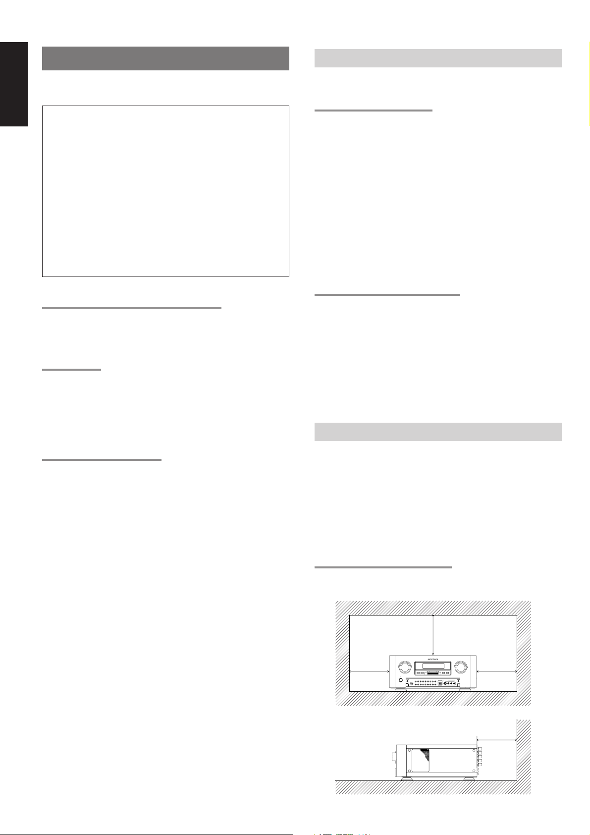
CAUTIONS ON INSTALLATION
For heat dispersal, leave at least 20 cm/8 inch of space between the
top, back and sides of this unit and the wall or other components.
•Do not obstruct the ventilation holes.
20 cm (8 ins.)
AV SURROUND RECEIVER SR-12S1SURROUND
TUNER
F/P
STAMDBY
POEWER ON/OFF
TV CD-R/MD
VCR2/DVD-R
VCR1DVD
PHONES
MEMOAUX2 CLEARATT
AUX1
S-DIRECT
7.1CH INPUT
VOLUME
DOWN
GYRO TUNINGDOWN UP
TAPECDDSS
MULTI ROOMLDMULTI SPKR.
UP
AUTO-TUNE
T-MODE
AUX1 INPUT
S-VIDEO
L
AUDIO
R
VIDEO
DIGITAL
20 cm (8 ins.)
Page 6

FEATURES
AMPLIFIER FEATURES
• THX Ultra certified
7ch amplifiers have enough power for even the most difficult
conditions found in large rooms.
Enormous power reserves endow the system with substantial
dynamic ability at high sound levels.
160 watts to each of the seven main channels the power amp section
features an advanced, premium high- storage power supply
capacitors, and fully discrete output stages housed in cast aluminum
heat sinks .
• Current feedback 7ch Amplifier
Current feedback topology combines total operation stability with
excellent frequency response,
while requiring only minimal amounts of negative feedback.
It makes excellent transient response and superb sonic transparency.
AUDIO/VIDEO FEATURES
• THX SURROUND EX built in to decode the additional two surround
buck channels from THX Surround EX-encoded DVDs and
laserdiscs.
• DTS-ES decoder built in to decode the impeccable 6.1-channel
discrete digital audio from DTS-ES encoded DVD-Video discs,
DVD-Audio discs, CDs and laserdiscs.
• DOLBY DIGITAL decoder built in to decode the 5.1-channel digital
audio of DVDs, Digital TV, HDTV, satellite broadcasts and other
sources.
• DOLBY PRO LOGIC II decoder provides better spatiality and
directionality on Dolby Surround program material; provides a
convincing three-dimensional sound field on conventional stereo
music recordings.
• HDCD decoding capability to deliver the full sonic benefits of
HDCD-encoded CDs from a standard non-HDCD CD player when
connected to the SR-12S1 via the player ’s digital output.
• CIRCLE SURROUND II decoder built in to decode surround sound
from any stereo or passive matrix-encoded material.
• Multi-channel (7.1ch)direct inputs accommodate future multichannel sound formats or an external digital decoder.
• 192kHz/24-bit D/A CONVERTERS for all channels.
• ADDC (Advanced Double Differential Converter) output for
STEREO playback.
• Source Direct mode bypasses, tone controls and bass
management for purest audio quality.
• Easy to use on-screen menu system in all video monitor output.
FLEXBILITY FEATURES
FUTURE-PROOF INTERFACE ARCHITECTURE
a versatile RS232 port allows the SR-12S1’s internal Flash Memory to
be directly computer accessed for installing such future upgrades as
new DSP algorithms, new surround formats/parameters, and other
types of processing updates.
MULTIROOM CAPABILITY
a full set of line outs for audio, composite video, allows for set-up of an
additional system in another room, and complete second-room control
can be achieved with such A/V distribution control systems as
Xantech, Niles, to name but a few.
Digital I/O
Assignable nine Digital inputs, for connection to other sources, such
as DVD, DSS, CD or LD.
A optical Digital input on front AUX1 terminals, for connection to
portable player or game.
Two Digital outputs for connection to digital recorder as CD-R or MD.
OTHER FEATURES
• High-quality AM/FM tuner with 50 station presets.
• 2way programmable learning remote control RC3200.
ENGLISH
3
Page 7
ENGLISH
DESCRIPTION
THX® is an exclusive set of standards and technologies established by
the world-renowned film production company, Lucasfilm Ltd. THX
resulted from George Lucas’ desire to reproduce the movie
soundtrack as faithfully as possible both in the movie theater and in
the home theater.
THX engineers developed patented technologies to accurately
translate the sound from a movie theater environment into the home,
correcting the tonal and spatial errors that occur.
When the THX mode of the SR-12S1 is on, three distinct THX
technologies are automatically added:
Re-Equalization-restores the correct tonal balance for watching a
movie in a home environment.
These sounds are otherwise mixed to be brighter for a large movie
theater. Re-EQ compensates for this and prevents the soundtracks
from being overly bright and harsh when played in a home theater.
Timbre Matching-filters the information going to the surround
speakers so they more closely match the tonal characteristics of the
sound coming from the front speakers.
This ensures seamless panning between the front and surround speakers.
Adaptive Decorrelation-slightly changes one surround channel’s time
and phase relationship with respect to the other surround channel.
This expands the listening position and creates with only two surround
speakers the same spacious surround experience as in a movie
theater with multiple surround speakers.
The Marantz SR-12S1 was required to pass a rigorous series of
quality and performance tests, in addition to incorporating the
technologies explained above, in order to be THX Ultra certified by
Lucasfilm Ltd.
THX Ultra requirements cover every aspect of performance including
pre-amplifier and power amplifier performance and operation, and
hundreds of other parameters in both the digital and analog domain.
Movies which have been encoded in Dolby Digital, DTS, Dolby Pro Logic,
stereo and Mono will all benefit from the THX mode when being viewed.
The THX mode should only be activated when watching movies which
were originally produced for a movie theater environment.
THX need not be activated for music, movies made especially for TV,
or shows such as sports programming, talk shows, etc.
This is because they were originally mixed for a small room
environment.
®
“Lucasfilm
Lucasfilm and THX are trademarks or registered trademarks of
Lucasfilm Ltd. ©Lucasfilm Ltd. & TM. Surround EX is a jointly
developed technology of THX and Dolby Laboratories, Inc. and is a
trademark of Dolby Laboratories, Inc. All rights reserved. Used under
authorization.
” and “THX®” are registered trademarks of Lucasfilm Ltd.
B.G.C. (Boundary Gain Compensation)
“If your chosen listening room layout (for practical or aesthetic
reasons) results in most of the listeners being close to the rear wall,
the resulting bass level can be sufficiently reinforced by the boundary
that the overall sound quality becomes ‘boomy’. THX Ultra2 receivers
contain the BGC (Boundary Gain Compensation) feature to provide an
improved bass balance. BGC can be selected by choosing ‘THX
Ultra2 Subwoofer-Yes’ from the ‘Boundary Gain Compensation’
section of the ‘THX Audio setup menu’.
THX Surround EX - Dolby Digital Surround EX is a joint development
of Dolby Laboratories and the THX division of Lucasfilm Ltd.
In a movie theater, film soundtracks that have been encoded with
Dolby Digital Surround EX technology are able to reproduce an extra
channel which has been added during the mixing of the program.
This channel, called Surround Back, places sounds behind the
listener in addition to the currently available front left, front center,
front right, surround right, surround left and subwoofer channels.
This additional channel provides the opportunity for more detailed
imaging behind the listener and brings more depth, spacious
ambience and sound localization than ever before.
Movies that were created using the Dolby Digital Surround EX
technology when released into the home consumer market may
exhibit a Dolby Digital Surround EX logo on the packaging.
A list of movies created using this technology can be found on the
Dolby web site at
http ://www.dolby.com.
“SURROUND EX ™” is a trademark of Dolby Laboratories. Used
under authorization.
DTS was introduced in 1994 to provide 5.1 channels of discrete digital
audio into home theater systems.
DTS brings you premium quality discrete multi-channel digital sound
to both movies and music.
DTS is a multi-channel sound system designed to create full range
digital sound reproduction.
The no compromise DTS digital process sets the standard of quality
for cinema sound by delivering an exact copy
of the studio master recordings to neighborhood and home theaters.
Now, every moviegoer can hear the sound exactly as the moviemaker
intended.
DTS can be enjoyed in the home for either movies or music on of
DVD’s, LD’s, and CD’s.
“DTS” and “DTS Digital Surround” are registered trademarks of Digital
Theater Systems, Inc.
The THX Ultra2 specification provides uncompromised 7.1 channel
playback of any multi-channel program, whether movie soundtracks or
music over the widest possible seating area.
There are an additional two processing’s for THX Ultra2 as bellow.
A.S.A. (Advanced Speaker Array)
“ASA is a proprietary THX technology which processes the sound fed
to 2 surround and 2 surround back speakers to provide the optimal
surround sound experience. When you set up your home theater
system using all eight speaker outputs (Left, Center, Right, Surround
Right, Surround Back Right, Surround Back Left, Surround Left and
Subwoofer), placing the two Surround Back speakers close together
facing the front of the room as shown in the diagram will provide the
largest sweet spot. If for practical reasons you have to place the
Surround Back speakers apart, you will need to go to the THX Audio
Set-up screen and choose the setting that most closely corresponds
to the speaker distance, which will re-optimize the surround soundfield. ASA is used in two new surround modes; THX Ultra2 Cinema
and THX Music Mode.
4
The advantages of discrete multichannel systems over matrix are well
known.
But even in homes equipped for discrete multichannel, there remains
a need for high-quality matrix decoding. This is because of the large
library of matrix surround motion pictures available on disc and on
VHS tape; and analog television broadcasts.
The typical matrix decoder of today derives a center channel and a
mono surround channel from two-channel matrix stereo material. It is
better than a simple matrix in that it includes steering logic to improve
separation, but because of its mono, band-limited surround it can be
disappointing to users accustomed to discrete multichannel.
Neo 6 offers several important improvements as follow,
• Neo 6 provides up to six full-band channels of matrix decoding from
stereo matrix material. Users with 6.1 and 5.1 systems will derive
six and five separate channels, respectively, corresponding to the
standard home-theater speaker layouts.
Page 8
• Neo 6 technology allows various sound elements within a channel
or channels to be steered separately, and in a way which follows
naturally from the original presentation.
• Neo 6 offers a music mode to expand stereo nonmatrix recordings
into the five- or six-channel layout, in a way which does not diminish
the subtlety and integrity of the original stereo recording.
DTS-ES Extended Surround is a new multi-channel digital signal
format developed by Digital Theater Systems Inc. While offering high
compatibility with the conventional DTS Digital Surround format, DTSES Extended Surround greatly improves the 360-degree surround
impression and space expression thanks to further expanded
surround signals. This format has been used professionally in movie
theaters since 1999.
In addition to the 5.1 surround channels (FL, FR, C, SL, SR and LFE),
DTS-ES Extended Surround also offers the SB (Surround Back)
channel for surround playback with a total of 6.1 channels. DTS-ES
Extended Surround includes two signal formats with different
surround signal recording methods, as DTS-ES Discrete 6.1 and DTSES Matrix 6.1.
“DTS”, “DTS-ES Extended Surround” and “Neo:6” are trademarks of
Digital Theater Systems, Inc.
Dolby Digital EX creates six full-bandwidth output channels from 5.1channel sources. This is done using a matrix decoder that derives
three surround channels from the two in the original recording. For
best results, Dolby Digital EX should be used with movies soundtracks
recorded with Dolby Digital Surround EX.
Manufactured under license from Dolby Laboratories. “Dolby”, “Pro
Logic”, and the double-D symbol are trademarks of Dolby
Laboratories.
Circle Surround II (CS-II ) is a powerful and versatile multi-channel
technology. CS-II is designed to enable up to 6.1 multi-channel
surround sound playback from mono, stereo, CS encoded sources
and other matrix encoded sources. In all cases the decoder extends it
into 6 channels of surround audio and a LFE/subwoofer signal. The
CS-II decoder creates a listening environment that places the listener
“inside” music performances and dramatically improves both hi-fi
audio conventional surround-encoded video material. CS-II provides
composite stereo rear channels to greatly improve separation and
image positioning – adding a heightened sense of realism to both
audio and A/V productions.
CS-II is packed with other useful feature like dialog clarity (SRS Dialog)
for movies and cinema-like bass enrichment (TruBass). CS-II can
enable the dialog to become clearer and more discernable in movies
and it enables the bass frequencies contained in the original
programming to more closely achieve low frequencies – overcoming the
low frequency limitations of the speakers by full octave.
ENGLISH
The stereo CD is a 16-bit medium with sampling at 44.1 kHz.
Professional audio has been 20- or 24-bit for some time, and there is
increasing interest in higher sampling rates both for recording and for
delivery into the home. Greater bit depths provide extended dynamic
range. Higher sampling rates allow wider frequency response and the
use of anti-alias and reconstruction filters with more favorable aural
characteristics.
DTS 96/24 allows for 5.1channel sound tracks to be encoded at a rate
of 96kHz/24bits on DVD-Video titles.
When DVD-video appeared, it became possible to deliver 24-bit, 96
kHz audio into the home, but only in two channels, and with serious
limitations on picture. This capability has had little use.
DVD-audio allows 96/24 in six channels, but a new player is needed,
and only analog outputs are provided, necessitating the use of the D/A
converters and analog electronics provided in the player.
DTS 96/24 offers the following:
1. Sound quality transparent to the original 96/24 master.
2. Full backward compatibility with all existing decoders. (Existing
decoders will output a 48 kHz signal)
3. No new player required: DTS 96/24 can be carried on DVD-video, or
in the video zone of DVD-audio, accessible to all DVD players.
4. 96/24 5.1-channel sound with full-quality full-motion video, for
music programs and motion picture soundtracks on DVD-video.
SRS Circle Surround II , SRS Dialog, SRS TruBass, SRS and
symbol are trademarks of SRS Labs, Inc.
SRS Circle Surround II , SRS Dialog and SRS TruBass technology are
incorporated under license from SRS Labs, Inc.
®
HDCD® (High Definition Compatible Digital ®) is a patented process for
delivering on Compact Disc the full richness and details of the original
microphone feed.
HDCD encoded CDs sound better because they are encoded with 20bits of real musical information as compared to 16-bits for all other CDs.
HDCD overcomes the limitation of the 16-bit CD format by using a
sophisticated system to encode the additional four bits onto the CD
while remaining completely compatible with the CD format.
When listening to HDCD recordings, you hear more dynamic range, a
focused 3-D sound stage, and extremely natural vocal and musical
timbre. With HDCD, you get the body, depth and emotion of the
original performance not a flat, digital imitation.
®, HDCD®, High Definition Compatible Digital ® and Pacific
Microsonics™ are either registered trademarks or trademarks of
Pacific Microsonics, Inc. in the United States and/or other countries.
HDCD system manufactured under license from Pacific Microsonics,
Inc. This product is covered by one or more of the following: In the
USA: 5,479,168, 5,638,074, 5,640,161, 5,808,574, 5,838,274,
5,854,600, 5,864,311, 5,872,531, and in Australia: 669114. Other
patents pending.
Dolby Digital identifies the use of Dolby Digital (AC-3) audio coding for
such consumer formats as DVD and DTV. As with film sound, Dolby
Digital can provide up to five full-range channels for left, center, and
right screen channels, independent left and right surround channels,
and a sixth ( ".1") channel for low-frequency effects.
Dolby Surround Pro Logic II is an improved matrix decoding
technology that provides better spatiality and directionality on Dolby
Surround program material; provides a convincing three-dimensional
soundfield on conventional stereo music recordings; and is ideally
suited to bring the surround experience to automotive sound. While
conventional surround programming is fully compatible with Dolby
Surround Pro Logic II decoders, soundtracks will be able to be
encoded specifically to take full advantage of Pro Logic II playback,
including separate left and right surround channels. (Such material is
also compatible with conventional Pro Logic decoders.)
5
Page 9
ENGLISH
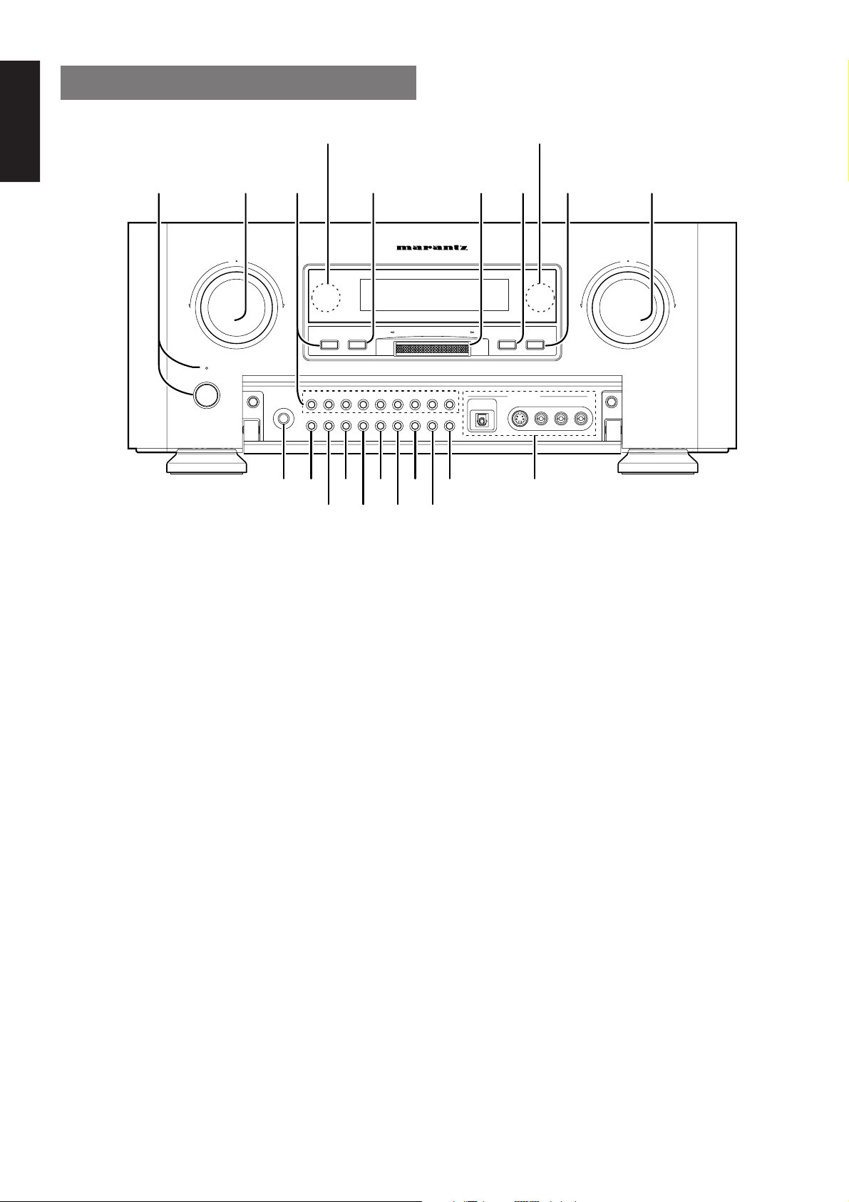
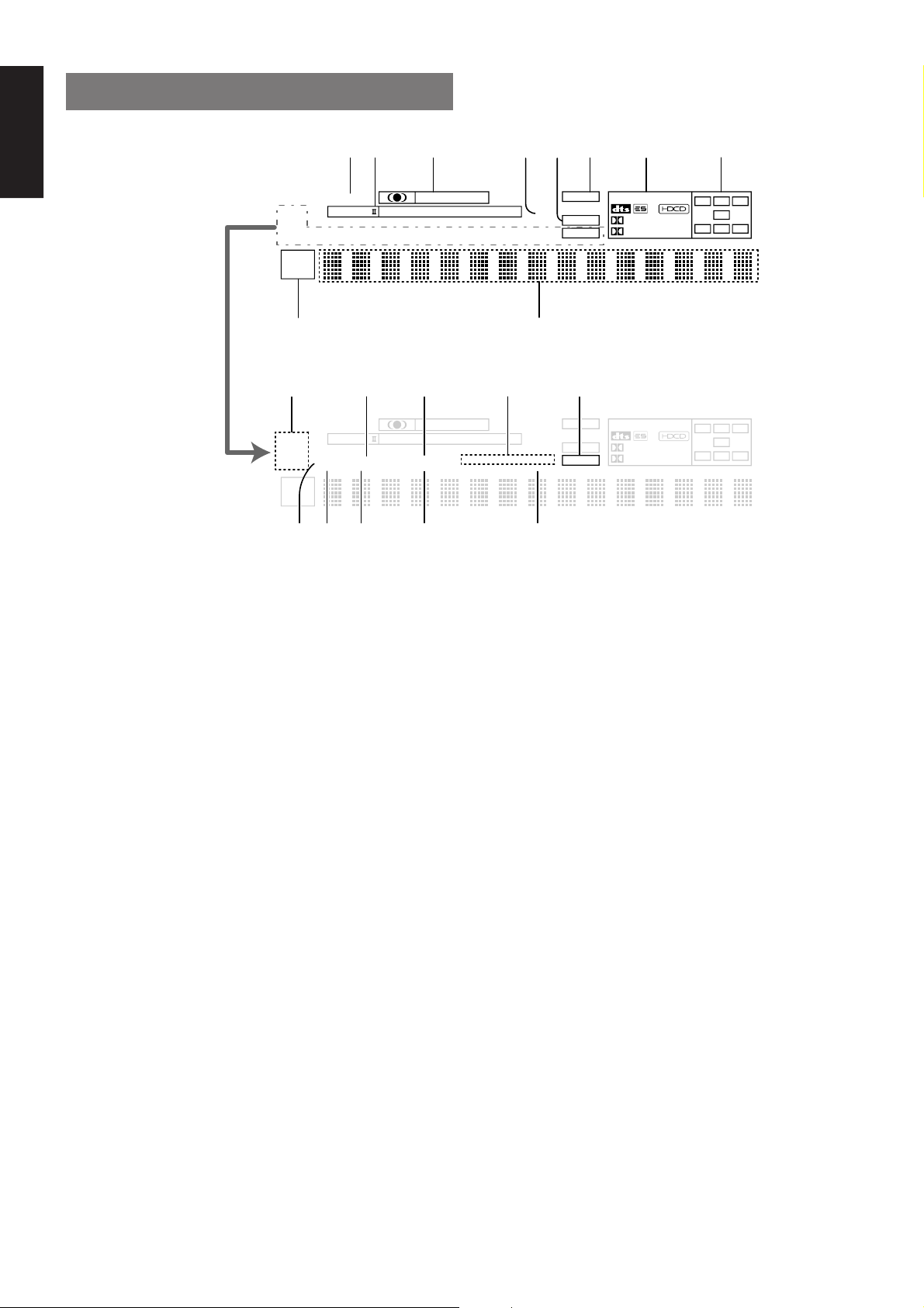
FRONT PANEL
@0 @1
STAMDBY
POEWER ON/OFF
LD
PHONES
AUX1
!9 !8
TUNER
!7
F/P
TV CD-R/MD
VCR2/DVD-R
VCR1DVD
MEMOAUX2 CLEARATT
S-DIRECT
7.1CH INPUT
!5 !3
AV SURROUND RECEIVER SR-12S1SURROUND
GYRO TUNINGDOWN UP
TAPECDDSS
MULTI ROOM
MULTI SPKR
!1
yt
DOWN
AUTO TUNE
T-MODE
AUX1 INPUT
S-VIDEO
DIGITAL
L
AUDIO
VIDEO
R
iurewq
VOLUME
UP
o!6 !4 !2 !0
q POWER switch and STANDBY indicator
You can turn on and off the unit’s power using the front panel power
switch.
However, if you turn the unit off with the front panel switch, the unit
goes completely off rather than to the “standby mode” (Red LED
indicator light glows in the standby mode).
The unit cannot be turned on with the remote control when it is not in
the standby mode. When the red LED is on, the unit can be turned on
via the remote control or by pressing any input selector button on the
front panel.
w SURROUND MODE Selector & MULTI
FUNCTION control dial
This dial changes surround mode sequentially or select contents of
OSD menu system.
e INPUT FUNCTION SELECTOR buttons
(AUDIO/ VIDEO)
These buttons are used to select the input sources.
The video function selector, such as TV, LD, DVD, DSS, VCR1 and
VCR2/DVD-R, selects video and audio simultaneously.
Audio function sources such as CD, TAPE, CD-R/MD, and TUNER
may be selected in conjunction with a Video source.
This feature (Sound Injection) combines a sound from one source with
a picture from another.
Choose the video source first, and then choose a different audio
source to activate this function.
Press TUNER button to switch the between FM or AM (LW/MW).
r F/P (FREQUENCY / PRESET) button
During reception of AM or FM, you can change the function of the
GYRO TUNING dial for scanning frequencies or selecting preset
stations by pressing these buttons.
t GYRO TUNING dial
Rotate this dial to change the frequency or the preset number.
y AUTO TUNE button
When this button is pressed and Auto scan function starts when the
GYRO TUNING dial is rotated.
u T-MODE button
Press this button to select the auto stereo mode or mono mode when
the FM band is selected.
The “AUTO” indicator lights in the auto stereo mode.
i VOLUME control knob
Adjusts the overall sound level. Turning the control clockwise
increases the sound level.
o AUX1 input jacks
These auxiliary video/audio and optical digital input jacks accept the
connection of a camcorder, portable DVD, game etc.
!0 MULTI ROOM button
Press this button to activate the Multiroom system . “MULTI ” indicator
will light in the display.
!1 MULTI SPKR (Multi Room Speaker)
button
Press this button to activate the Multiroom Speaker system . “MSPKR” indicator will light in the display.
!2 CLEAR button
Press this button to cancel the station-memory setting mode or preset
scan tuning.
6
Page 10

!3 MEMO (memory) button
Press this button to enter the tuner preset memory numbers or station
names.
!4 S (Source)-DIRECT button
When this button is pressed, the tone control circuitry is bypassed as
well as Bass Management.
Notes:
• The surround mode is automatically switched to AUTO when
the source direct function is turned on.
• Additionally, Speaker Configurations are fixed automatically
as follow.
• Front SPKR = Large, Center SPKR = Large, Surround SPKR =
Large, Sub woofer = On
!5 ATT (Attenuate) button
If the selected analog audio input signal is greater than the capable
level of internal processing, PEAK indicator will light. If this happens,
you should press the ATT button. “ATT” is displayed when this
function is activated.
The signal-input level is reduced by about the half. Attenuation will not
work with the output signal of “REC OUT” (TAPE, CD-R/MD, VCR1 and
VCR2/DVD-R output). This function is memorized for each input function.
!6 7.1CH INPUT button
Press this button to select the 7.1CH INPUT.
ENGLISH
!7 AUX2 button
This button is used to select the AUX2 (L/R input of 7.1 CH. IN).
!8 AUX1 button
This button is used to select the AUX1 input source.
!9 PHONES jack for stereo headphones
This jack may be used to listen to the SR-12S1’s output through a pair
of headphones. Be certain that the headphones have a standard 1 / 4"
stereo phone plug. Note that the main room speakers will
automatically be turned off when the headphone jack is in use.
Notes:
• When using headphones, the surround mode will automatically
change to STEREO.
• The surround mode returns to the previous setting as soon as the
plug is removed from the jack.
@0 INFRARED transmitting sensor window
This window transmits infrared signals for the remote control unit.
@1 INFRARED receiving sensor window
This window receives infrared signals for the remote control unit.
7
Page 11
ENGLISH
FL DISPLAY
kjhgfdsa
DISP
PRO LOGIC
ST
AUTO
TUNED
MULTI
SLEEP
M-SPKR
DIRECT
TEST
AUTO SURR
COPY
¡0
DISP
PRO LOGIC
ST
AUTO
TUNED
MULTI
SLEEP
M-SPKR
DIRECT
TEST
AUTO SURR
COPY
¡9™0 ¡8 ¡6¡7
MOVIE
THX SURR EX
MOVIE
THX SURR EX
CINEMA
MUSIC
NIGHT
CINEMA
MUSIC
NIGHT
MUSIC
PRO LOGIC
DISC 6.1
MUSIC
PRO LOGIC
DISC 6.1
AT T
MTX 6.1
SLEEP
l
AT T
MTX 6.1
SLEEP
ANALOG
DIGITAL
PEAK
¡5¡4¡2 ¡3¡1
ANALOG
DIGITAL
PEAK
OTHER
DIGITAL
SURROUND
OTHER
DIGITAL
SURROUND
PCM
96kHz
PCM
96kHz
C
L
LFE
SL S SR
C
L
LFE
SL S SR
R
R
a DISP (Display Off) indicator
This indicator lights when the SR-12S1 is in the display off condition.
s PRO LOGIC II mode indicators (MOVIE,
MUSIC, PRO LOGIC)
These indicators illuminate when one of the Dolby Pro Logic II modes
is in use.
d Circle Surround mode indicators
(CINEMA, MUSIC)
These indicators illuminate when one of the Circle Surround modes is
in use.
f ATT (Attenuation) indicator
This indicator lights when the attenuation function is active.
g DIGITAL Input Indicator
This indicator lights when digital input has been selected.
h ANALOG input indicator
This indicator lights when an analog input source has been selected.
j SIGNAL FORMAT indicators
2 DIGITAL, 2 SURROUND, dts, ES, PCM, 96kHz, HDCD, and
OTHER
When the selected input is a digital source, some of these indicators
will light to display the specific type of signal in use.
k ENCODED CHANNEL STATUS
indicators
These indicators display the channels that are encoded with a digital
input signal. If the selected digital input signal is Dolby Digital 5.1ch or
DTS 5.1ch, “L”, “C”, “R”, “SL”, “SR” and “LFE” will light up. If the digital
input signal is 2 channel PCM-audio, “L” and “R” will be displayed.
If Dolby Digital 5.1ch signal with Surround EX flag or DTS-ES signal
comes in, “L”, “C”, “R”, “SL”, “S”, “SR” and “LFE” will show.
l Main Information Display
This display shows messages relating to the status, input source,
surround mode, tuner, volume level or other aspects of unit’s
operation.
¡0 Multi-room system indicator
MULTI : This indicator lights when the multi-room system is active.
SLEEP : This indicator lights when the sleep timer to multi-room
system is active.
M-SPKR : This indicator lights when the Multi-room Speaker output
is active.
¡1 TUNER’s indicators
ST (Stereo) : This indicator illuminates when an FM station is being
tuned in stereo condition.
AUTO : This indicator illuminates when the tuner’s Auto mode
is in use.
TUNED : This indicator illuminates when a station is being
received with sufficient signal strength to provide
acceptable listening quality.
8
Page 12

¡2 AUTO.SURR (Auto Surround mode)
indicator.
This indicator illuminates to show that the AUTO SURROUND mode is
in use.
¡3 THX SURR EX (THX Surround EX mode)
indicator.
When THX surround EX mode is selected , this indicator lights.
¡4 DTS-ES mode indicators (DISC6.1,
MTX6.1)
These indicators will show to DTS-ES decoding mode.
¡5 PEAK indicator
This indicator is a monitor for an analog audio input signal. If the
selected analog audio input signal is greater than the capable level of
internal processing, this will light. If this happens, you should press the
ATT button.
¡6 SLEEP timer indicator
This indicator lights when the seep timer function in main-room is in
use.
¡7 NIGHT mode indicator
This indicator lights when the SR-12S1 is in the Night mode, which
reduces the dynamic range of digital program material at low volume
levels.
¡8 COPY indicator
This indicator lights when DIGITAL COPY system is active.
ENGLISH
¡9 TEST tone indicator
This indicator blinks in generating the test tone in speaker level setup.
™0 DIRECT (Source direct) indicator
This indicator lights when the SR-12S1 is in the SOURCE DIRECT
mode.
9
Page 13

ENGLISH
REAR PANEL
cv b nxz m . Ú0,
DIGITAL-OUT
OPT
COAX
RS232C
EXT. IR
OUT
DC OUT 2
DC OUT 1
OUTIN
MULTI
RC
RC-5
Ú7Ú8Ú9
DIGITAL-IN
Ú5 Ú4 Ú3 Ú2 Ú1Ú6
MAIN IN
PRE OUT
1
L
2
R
3
C
4
SW
5
SL
6
SR
7
SBL
SBR
8
MULTI
9
OUT
RL
GND
ANTENNA
GND
AM
FRONT
(AUX 2)
SURR.
SURR.
BACK
SUB WOOFER
7.1CH-INPUT
MULTI VIDEO
OUT
MODEL NO.SR-12S1
R
L
CD
IN
TAPE
OUT
IN
CD-R
CENTER
/MD
OUT
AUDIO
R
LR
z DIGITAL INPUT (Dig.1 - 9) / OUTPUT
(coaxial, optical)
These are the digital audio inputs and outputs. There are 5 digital
inputs with coaxial jacks, 4 with optical jacks.
The inputs accept digital audio signals from a compact disc, LD, DVD,
or other digital source component.
For digital output, there is 1 coaxial output and 1 optical output.
The digital outputs can be connected to MD recorders, CD recorders,
DAT decks, or other similar components.
+
–
OUT
VCR2 /
DVD - R
IN
VCR1
IN
–
FRONT
LEFT
FRONT
RIGHT
SURR.
BACK
LEFT
SURR.
BACK
RIGHT
SPEAKER SYSTEMS
6-8 OHMS
AC IN
MONI.
2
MONI.
Y
1
LD
DVD
DSS
TV
IN
VCR1
OUT
IN
VCR2/
DVD-R
OUT
L
S-VIDEOVIDEO
MONITOR
CB
CR
Y
DSS
IN
CB
CR
Y
DVD
IN
CB
CR
COMPONENT VIDEO
MULTI
ROOM
LEFT
MULTI
ROOM
RIGHT
CENTER
SURR.
LEFT
SURR.
RIGHT
+
b FM antenna terminal (75 ohms)
Connect an external FM antenna with a coaxial cable, or a cable
network FM source.
AM antenna and ground terminals
Connect the supplied AM loop antenna. Use the terminals marked
“AM” and “GND”. The supplied AM loop antenna will provide good
AM reception in most areas. Position the loop antenna until you hear
the best
x Preamp Outputs (L, R, SL, SR, SBL,
SBR, C)
When the jumper plugs that link the Amplifier Inputs with these outputs
are removed, these jacks may be connected to an external power
amplifier.
c Subwoofer Output
Connect this jack to the line level input of a powered subwoofer. If an
external subwoofer amplifier is used, connect this jack to the
subwoofer amplifier input. If you are using two subwoofers, either
powered or with a 2 channel subwoofer amplifier, connect a “Y”
connector to the subwoofer output jack and run one cable from it to
each subwoofer amplifier.
v Main Amplifier Inputs
When the jumper plugs that link the Preamp Outputs with these inputs
are removed, these jacks may be used to connect an external source
to the internal amplifiers.
Notes:
• When connecting a equipment, remove the attached jumper
plugs and store them carefully so as not to lose them.
• Only remove the jumper plugs when required. After you finish
using an Main Amp Input jack, replace the jumper plug.
10
n Multiroom Outputs (Audio L&R, Video)
These are the audio and video output jacks for the remote zone (Multi
Room).
Connect these jacks to the optional audio power amplifiers or video
display devices to view and listen to the source selected by the
mulitroom system in a remote room.
m MONITOR OUT
There are 2 monitor outputs and each one includes both composite
video and S-video configurations. When connecting two video
monitors or televisions, be aware that the OSD interface can be used
with both MONITOR OUT.
, COMPONENT VIDEO INPUT/OUTPUT
If your DVD player or other device has component video connectors,
be sure to connect them to these component video connectors on the
SR-12S1. The SR-12S1 has four component video input connectors
to obtain the color information (Y, C
DVD signal or other video component and one component video
output connector to output it directly into the matrix decoder of the
display device.
By sending the pure DVD component video signal directly, the DVD
signal forgoes the extra processing that normally would degrade the
image. The result is vastly increased image quality, with incredibly
lifelike colors and crisp detail.
Notes:
• This component video output is available to OSD menu system.
B
, CR) directly from the recorded
Page 14

. Speaker outputs terminals (for Main
room)
Seven terminals are provided for the front left, front right, front center,
surround left, surround right, surround back left, and surround back
right speakers.
⁄0 Speaker outputs terminals (for Multi
room)
Two terminals are provided for the left and right speakers for
Multiroom (2nd zone)
Notes:
• Connect the these jacks to the matching + or – terminals on your
speakers. When making speaker connections, always make
certain to maintain correct polarity by connecting the red (+)
terminals on the SR-12S1 to the red terminals on the speaker
and the black (–) terminals on the SR-12S1 to the black
terminals on the speakers.
⁄1 AC INLET
Plug the supplied power cord into this AC INLET and then into the
power outlet on the wall.
⁄2 VIDEO IN/OUT (TV, DVD, DSS, LD,
VCR1, VCR2/DVD-R)
These are the video inputs and outputs. There are 6 video inputs and
2 video outputs and each one includes both composite video and Svideo configurations. Connect VCRs, LD players, DVD players, and
other video components to the video inputs.
S-video sources can be viewed through the S-video outputs, and
composite sources can only be viewed through the composite output.
The 2 video output channels can be used to be connected to video
tape recorders for making recordings.
⁄6 REMOTE CONT. IN/OUT terminals
Connect to a Marantz component equipped with remote control (RC-
5) terminals.
⁄7 MULTI ROOM REMOTE IN/OUT
terminals
IN: Connect to multi-room remote control device, available from
your Marantz dealer.
OUT: Connect to the Marantz component equipped with remote
control (RC-5) terminals in another room (Second zone).
⁄8 DC TRIGGER output terminals
Connect a device that needs to be triggered by DC under certain
conditions (screen, power strip, etc…)
Use the system OSD setup menu to determine the conditions by which
these jacks will be active.
Note:
• This output voltage is for (status) control only, It is not
sufficient for drive capability.
⁄9 External IR transmitter terminal
If the SR-12S1 is located inside a rack or cabinet that will not allow
infrared beams to transmit to 2way remote commander, you will need
to connect a IR transmitter to this output to be able to use the 2way
remote controller.
Then install the remote transmitter in an unblocked location where you
can easily receive IR signal.
Note:
• An optional remote transmitter kit is required.
ENGLISH
⁄3 AUDIO IN/OUT (CD, TAPE, CD-R/MD,
TV, DVD, DSS, LD, VCR1, VCR2/DVD-R)
These are the analog audio inputs and outputs. There are 9 audio
inputs (6 of which are linked to video inputs) and 4 audio outputs (2 of
which are linked to video outputs). The audio jacks are nominally
labeled for cassette tape decks, compact disc players,DVD players
and etc.... The audio inputs and outputs require RCA-type connectors.
⁄4 7.1 CHANNEL INPUT
By connecting a DVD Audio player, Super Audio CD player, or other
component that has a multi channel port, you can playback the audio
with 5.1 channel or 7.1 channel output.
⁄5 RS232C
The RS232C port is to be used in conjunction with an external controller
to control the operation of the SR-12S1 by using an external device.
The RS232C port may also be used in the future to update the
operating software of the SR-12S1 so that it will be able to support
new digital audio formats and the like as they are introduced.
11
Page 15
ENGLISH
REMOTE CONTROL UNIT RC3200
This chapter describes the functions which control the SR-12S1.
Please look at the user guide of the RC3200 for operation instructions.
12
11
ˆ
10
9
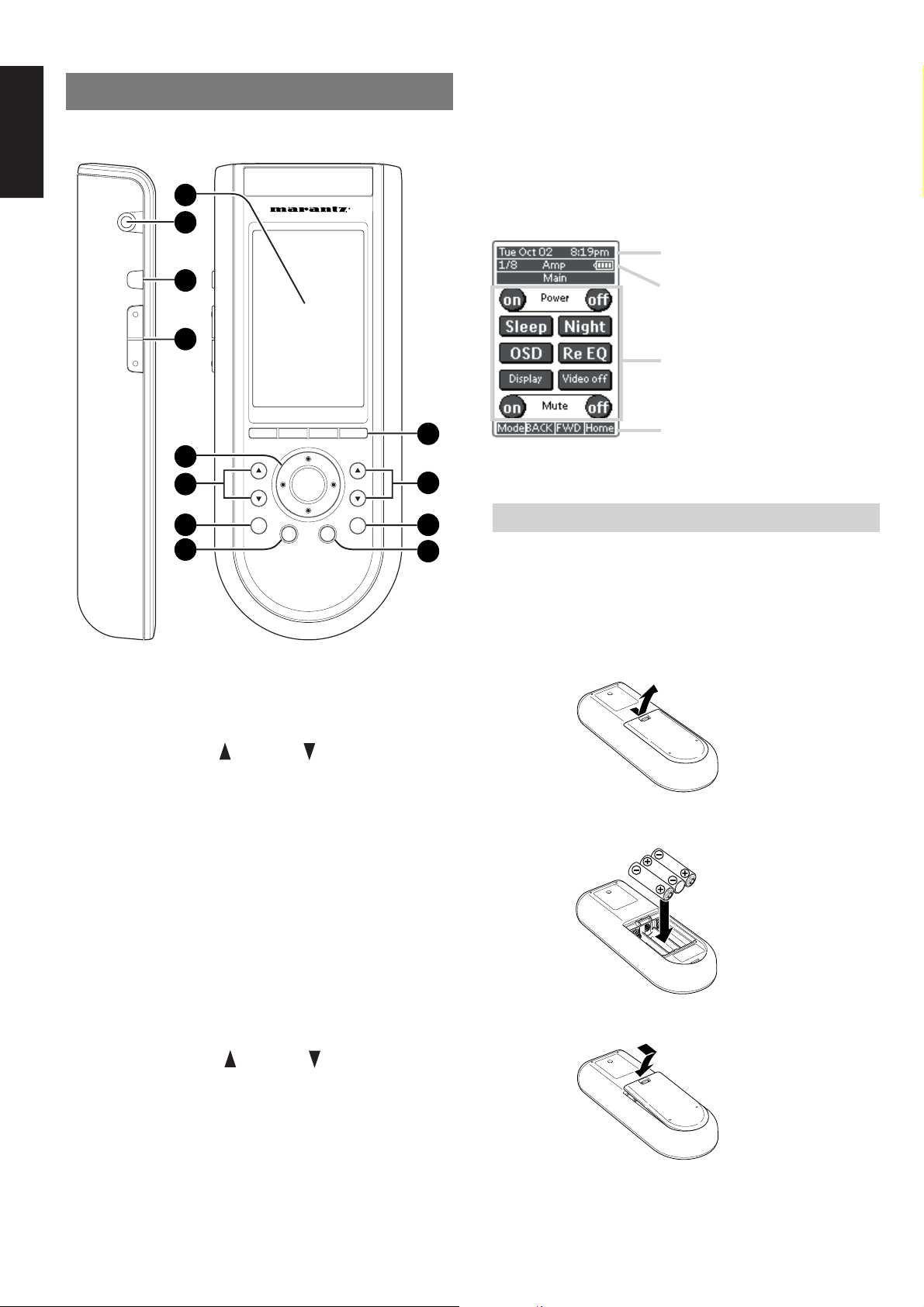
J ˆ button
Press this button turns on the backlight to LCD display.
K Serial port
To connect the RC3200 with your computer by attached serial cable
for future upgrades.
L LCD touch screen
The LCD touch screen is divided into different sections:
Here the date and time are displayed
when you are operating your devices.
In this area you can see:
· the page number;
· the device you are operating;
· the battery level indicator.
With these soft buttons you operate
your device.
1
8
7
6
VOL
H
OK
Ex
5
CH
S
M
2
3
4
A Select buttons to Navigation bar
These buttons work with navigation bar in LCD.
Each function may also be provided with an alphanumeric function
indicator visible in navigation bar of LCD display.
B CH (Channel) UP and DOWN buttons
Use these buttons to select the preset number of tuner in the SR-12S1
or channel of TV.
C S (Status) button
Press this button to see (jump to) the status of SR-12S1 on LCD
panel.
Navigation bar:
These are the labels of the 4 hard
buttons below the touch screen.
LOADING BATTERIES
When you use RC3200 for the first time, you have to install the
batteries.
The RC3200 requires 3 AA-batteries (3 x 1,5 V) to function.
Note
• Attached batteries are to check basic function of remote
commander, you can use either primary or rechargeable
batteries.
1.
Remove the back cover.
2.
Insert the new batteries (AA type) with correct (+) and (–) polarity.
D M (Menu) button
Use this button to entry the OSD menu system.
E Ex (Exit ) button
Press this button to exit on screen menu .
F H (mute) button
Press this button to mute the sound temporarily.
G VOL (Volume) UP and DOWN
buttons
Use these buttons to raise and lower the SR-12S1’s volume level.
H OK and cursor (Up / Down / Left / Right )
buttons
Use these buttons to navigate through on-screen menus.
(Refer to ”ON-SCREEN MENU SYSTEM” on page 31 - 37)
I Page scroll Up /Down buttons
Use these buttons to scroll up or down the device of LCD screen.
12
3.
Close until it clicks.
Page 16
ACTIVATING THE RC3200
When the RC3200 is switched on for the first time or when it is reset,
the Introduction screen appears for a few seconds. The RC3200 then
automatically switches to the HOME screen that displays all available
devices on your RC3200. You can return to this HOME screen from
within other screens by pressing the HOME button. See “Activating
the HOME screen” for more details.
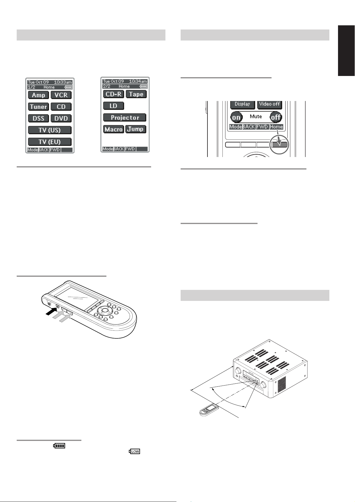
OPERATING DEVICES
To operate devices on your RC3200 you have to switch to the HOME
screen.
This screen displays the available devices like TV, VCR, DVD, Amp
and so on.
ENGLISH
ACTIVATING THE HOME SCREEN
Press the HOME button.
The HOME screen appears, showing the available devices in the
RC3200.
TURNING ON THE DISPLAY AND THE BACKLIGHT
RC3200’s display can be activated in two different ways: Tap the
touch screen gently with your finger or a blunt, soft object like a pencil
eraser.
The display is activated.
1.
Press ˆ button on the left side of the RC3200.
The display and the backlight are activated.
If the LCD touch screen stays blank or becomes black when
turning on the display, read the next section “Changing the
LCD Contrast” to adjust the contrast of the LCD touch screen.
Note :
• RC3200 has a timeout feature: the LCD touch screen and the
backlight automatically turn off to save power.
• See “Adjusting the Settings” to adjust the timeout for the LCD
and the backlight.
CHANGING THE LCD CONTRAST
SELECTING A DEVICE ON THE HOME SCREEN
Tap the soft button of the device you want to operate.
The first page of the selected device appears. “Using the page up and
page down Buttons” to go to another page of the device.
You operate devices using the buttons on your RC3200:
• Soft buttons (touch screen buttons);
• Hard buttons.
USING THE SOFT BUTTONS
By tapping the soft buttons on the LCD touch screen you send IR
commands to the device you have selected.
The name of the active device is indicated at the top of the touch
screen.
Note
• You can operate the soft buttons in the same way you operate
hard buttons on a conventional remote control. When you keep
the soft button pressed instead of tapping it, RC3200 keeps
sending the IR command.
REMOTE-CONTROLLABLE RANGE
The distance between the transmitter of the remote control unit and
the IR SENSOR of the SR-12S1 should be less than about 5 meters. If
the transmitter is pointed to a direction other than the IR SENSOR or if
there is an obstacle between them, remote control may not be
possible.
1.
Press and hold the Backlight (ˆ) button. The screen lights up.
2.
While still holding the Backlight (ˆ) button, press the page up
button once to increase the LCD contrast one level.
The LCD contrast is adjusted one level up. or press the page
down button once to decrease the LCD contrast one level. The
LCD contrast is adjusted one level down.
3.
Release the Backlight (ˆ) button when the contrast is
satisfactory. The LCD contrast can be adjusted 16 levels.
Note
• To adjust the contrast multiple levels, you have press the Page
Up or Page Down button multiple times.
• When you press and hold the page up or page down button, the
LCD contrast will only change one level.
THE BATTERY STATUS
The battery icon indicates the status of your batteries.
When the battery status is low, the Low Battery icon
the top of the touch screen.
You can still operate your devices, but you cannot adjust the settings,
learn commands or record macros anymore.
appears at
SR-12S1
Approx. 5 m
60°
Remote control unit (RC3200)
13
Page 17
ENGLISH
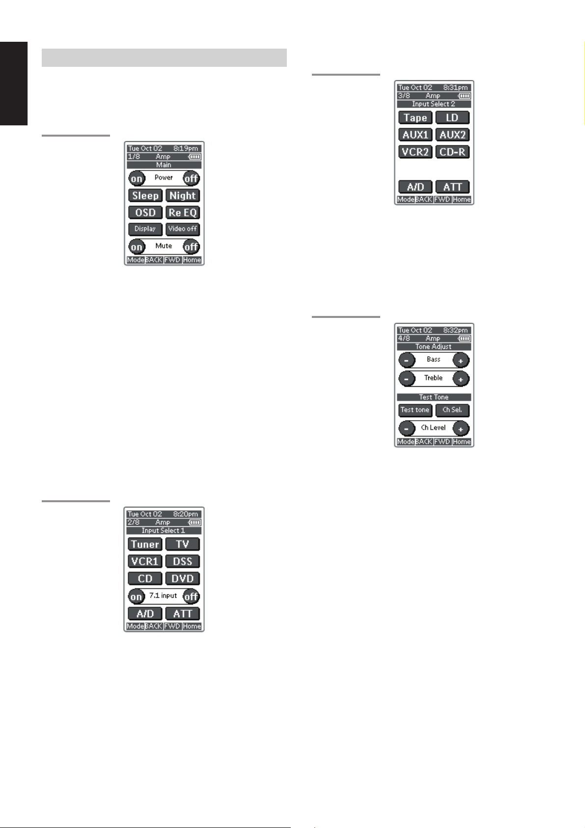
OPERATING AMP & TUNER
To control the SR-12S1 by your RC3200, you have to select the
device AMP or TUNER on HOME screen.
MAIN
AMP PAGE 1/8
Power on and off buttons
These buttons are used to turn on or off SR-12S1.
Sleep button
This button is used to set the sleep timer. (see page 39)
Night button
This button is used to set night mode. (see page 39)
Display button
This button is used to select the display mode for front display. (see
page 44)
Video off button
This button is used to turn off or on the video signal outputs from
MONITOR OUT terminals. (see page 44)
Cinema Re-EQ button
This button is used to active the Cinema Re-EQ™, press again this is
inactive.
OSD button
This button is used to turn on the On Screen Display for general
information.
You can find the current condition of SR-12S1.
INPUT SELECT 1
AMP PAGE 2/8
INPUT SELECT 2
AMP PAGE 3/8
Tape, LD, AUX1, AUX2, VCR2, CD-R
These buttons are used for selecting an input source. (see page 38)
A/D button
This button is used to select the Auto digital input, fixed digital input or
analog input. (see page 44)
ATT button
This button is used to attenuate to analog input signals. (see page 44)
TONE ADJUST
AMP PAGE 4/8
BASS + and –
These buttons are used to adjust the tone of low-frequency sound.
(see page 38)
Treble + and –
These buttons are used to adjust the tone of high-frequency sound.
(see page 38)
Test tone
This button is used to generate the test tone noise signal.
You can check the balance of output signal level.
Ch sel.
This button is used to change the test tone noise signal output
channel.
Ch. Level + and –
This button is used to adjust the output level of each channel.
Tuner, TV, VCR1, DSS, CD, DVD, buttons
These buttons are used for selecting an input source. (see page 38)
7.1 INPUT On/Off buttons
These buttons are used to select 7.1ch Input source. (see page 46)
A/D button
This button is used to select the Auto digital input, fixed digital input or
analog input. (see page 44)
ATT button
This button is used to attenuate to analog input signals. (see page 44)
14
Page 18
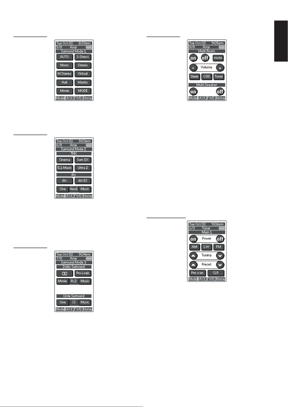
SURROUND MODE 1
AMP PAGE 5/8
MULTI ROOM
AMP PAGE 8/8
ENGLISH
AUTO, S-DIRECT, Mono, Stereo, M-Stereo (Multi channel stereo),
Virtual, hall, matrix, Movie.
These buttons are used to select surround mode. (see page 40, 41)
SURROUND MODE 2
AMP PAGE 6/8
THX
CINEMA and Surr.EX (THX Surround EX)
These buttons are used to select THX mode. (see page 40)
DTS
dts, dts-ES, Neo6-cinema and Neo6-music
These buttons are used to select DTS mode. (see page 40)
SURROUND MODE 3
AMP PAGE 7/8
On/Off
These buttons are used to switch the unit to multi room mode.
Volume + and –
These buttons are used to adjust the sound level to multiroom system.
Mute
This button is used to mute the sound to multi room system
temporarily.
Sleep
This button is used to set the sleep timer to multi room system.
Tuner
This button is to jump to TUNER's screen in this remote control unit.
OSD button
This button is used to turn on the On Screen Display for general
information.
Multi room speaker On and Off
These buttons are used to switch the unit to multi room speaker mode.
Note:
See page 51 to detail of Multi Room system.
TUNER
TUNER PAGE 1/3
DOLBY SURROUND
DD and PL (Pro Logic), PL2-movie, PL2-music
These buttons are used to select Dolby Surround mode. (see page 41)
Circle Surround
CSII-cinema and CSII-music
These buttons are used to select SRS Circle Surround mode. (see
page 41)
Note:
• Use MODE button (AMP page 5/8) to select CSII-Mono.
Power On and Off buttons
These buttons are used to turn on or off SR-12S1.
AM, LW, FM buttons
These buttons are used to switch between FM, AM, and LW mode of
the tuner.
Tuning (^ :up / v : down ) buttons
These buttons are used to change the frequency.
Preset (^ :up / v : down ) buttons
These buttons are used to change the preset station.
Preset Scan button
This button is used to start a scan automatically through the stations
preset into the receiver's memory.
CLR (Clear) button
This button is used to cancel certain memory or programming of tuner
operations.
15
Page 19

ENGLISH
TUNER PAGE 2/3
Frequency Direct button
This button is used to select the mode of frequency direct input.
Stereo/Mono button
This button is used to select the FM tuning mode, auto stereo or mono.
RDS Display button
Selects display mode function in RDS (Radio Data System) by this
button.
PTY button
Selects PTY function in RDS (Radio Data System) by this button.
TUNER PAGE 3/3
SHOW THE STATUS OF SR-12S1 ON THE
LCD OF RC3200
RC3200 has 2way communication with SR-12S1, it shows some
status screen for SR-12S1.
1/2 Status
To show 1st page of status screen, press S button .
This status screen shows Power condition, Volume level, Sleep timer,
Video Input ,and Audio input in Main room.
2/2 Status
If you desire to see 2nd page of status screen, press Page UP button.
Ten keypad (0, 1 - 9)
These buttons are used to change the preset station name or input
frequency directly.
Memo button
This button is used to enter the tuner's preset memory numbers and
station names.
CLR (Clear) button
This button is used to cancel certain memory or programming
operations.
This status screen shows surround mode, format and channel status
of input signal, in Main room.
Multiroom Status
If you desire to see status screen to Multiroom , press Multi button of
navigation bar.
This status screen shows Multiroom condition, Volume level, Sleep
timer, Video Input ,and Audio input in Multi room.
If you desired to exit from status screen, pres RTN button.
16
Page 20

WORKING WITH MODES
RC3200 starts up in Use mode. In this mode you operate your
devices. For customizing the RC3200 (adjusting the settings, learning
buttons or recording macros) you have to switch to the appropriate
mode.
Note
•When switching between modes you will always return to the
last active screen.
The RC3200 can be put into 4 different modes. These modes are:
Use mode: For operating your devices. See “Operating Devices”.
Setup mode: For changing the RC3200 system settings. See
Learn mode: For learning commands from other remote controls.
Macro mode: For recording macros. You can assign multiple
Note
• Learning commands and recording macros is only possible per
device. This means that you first have to select a specific device
to perform these actions.
1.
On the HOME screen tap the soft button of the device you want to
customize.
The first page of the selected device appears.
2.
Press and hold the Mode button for 3 seconds. The Mode screen
appears.
“Adjusting the Settings” for more details.
See “Learning Commands” for more details.
commands to one single button. See “Recording
Macros” for more details.
ADJUSTING THE SETTINGS
The RC3200 settings can be adjusted in the Setup mode.
1.
Press and hold the Mode button for 3 seconds.
The Mode screen appears.
2.
Tap Setup in the Mode screen.
The first Setup page appears.
The RC3200 settings consist of 3 setup pages with several settings
per page.
Use the Page Up and Page Down buttons to navigate to the
appropriate setup page.
FIRST SETUP PAGE
On the first setup page you can adjust:
• the LCD timeout;
• the backlight timeout;
• the beep volume.
ENGLISH
Note
You have to press and hold the Mode button for 3 seconds to
prevent accidental changes.
3.
Select the desired mode from the Mode screen.
Note
• When you switch to another mode from the HOME screen, you
cannot choose the Learn mode and Macro mode. To switch to
these modes you first have to go to the specific device you want
to customize.
Adjust the LCD Timeout
The LCD timeout indicates how long the LCD touch screen stays
active before it turns off.
The LCD will only time out when you don't touch any buttons.
You can set the timeout between 1 second and 120 seconds.
Press “+” to increase or “–” to decrease the time the LCD stays active.
1.
Tap “+” or “–”once to adjust the timeout 1 second up or down.
2.
Press and hold “+” or “–” to adjust the timeout per 10 seconds up
or down.
Adjust the Backlight Timeout
The backlight setting indicates how long the backlight of the LCD
touch screen and the buttons stays active.
The backlight timeout can be set between 1 second and 120 seconds.
Note
• The backlight cannot stay active longer than the LCD. If you
increase the backlight timeout, the LCD timeout will
automatically increase as well.
Press “+” to increase or “–” to decrease the time the backlight stays
active.
1.
Tap “+” or “–” once to adjust the timeout 1 second up or down.
2.
Press and hold “+” or “–” to adjust the timeout per 10 seconds up
or down.
Note
• When the settings for the LCD timeout and the backlight
timeout are high, the battery lifetime may be reduced.
Change the Beep volume
The beep volume setting adjusts or turns off the volume of all button
and system beeps on the RC3200. The beep volume levels are mute,
soft, medium and loud.
1.
Press “+” to increase or “–” to decrease the beep volume.
17
Page 21

ENGLISH
SECOND SETUP PAGE
On the second setup page you can adjust:
• the date;
• the time.
1.
Tap the Revert button.
A message screen appears to confirm or cancel the revert
process.
2.
Press OK or Cancel.
Adjust the Date
You can set the year, the month and the day in the date settings.
Press “+” to increase or “–” to decrease the value for the year, month
and day.
1.
Tap “+” or “–” once to adjust the year, month and day one value up
or down.
2.
Press and hold “+” or “–” to adjust the values for the year and the
month more rapidly. The value for the day settings will change per
5 days.
The RC3200 will immediately reflect the date change at the top of the
screen.
Adjust the Time
1.
Tap “+” or “–” once to adjust the time 1 minute up or down.
2.
Press and hold “+” or “–” to adjust the time more rapidly. The time
will increase or decrease per 30 minutes.
The RC3200 will immediately reflect the time change at the top of the
screen.
THIRD SETUP PAGE
RC3200 Information
TO EXIT SETUP MODE
1.
Press the Mode button.
The Mode screen appears.
2.
Tap the Mode button you want to go to.
RC3200 switches to this mode. See also “Working with Modes”.
This page contains information that may be important to the dealer in
case of a defect.
The following information is displayed on this screen:
• Free memory (in percentage), which gives you an indication on how
much memory is left to (further) customize the RC3200;
• Boot version;
• Application version;
• Configuration file.
Revert
Warning
• When you revert the RC3200, all customization is lost
permanently. You loose all RC3200 settings learned codes and
recorded macros.
By tapping the Revert button the RC3200 will be reverted to the
default configuration.
Reverting to the original configuration restores the RC3200 to its initial
state.
You might have to revert when you notice that scrolling through pages
is slowing down. This might be the case when you have added a lot of
commands to the RC3200.
18
Page 22

LEARNING COMMANDS
H
M
Ex
S
OK
H
M
Ex
S
OK
If an IR code or a brand is not in the database, you can program
RC3200 commands by transmitting IR signals from your existing
remote controls to RC3200's learning eye. To do this, place RC3200
and the device's remote control on a flat surface, 2 to 10 cm
apart.
Top View
DVD remote
control unit
OK
RC3200
NO GOOD
Top View
RC3200
7.
Press and hold the button on the existing remote control you want
to learn to the RC3200.
When the RC3200 receives an IR code:
• You hear a confirmation beep;
• The label changes from Learning to OK. The Learn sequence
has been successful.
ENGLISH
Side View
DVD remote
control unit
2 to 10 cm
To learn commands from other remote controls, RC3200 has to be in
Learn mode. Switching to Learn mode is only possible from a specific
device, not from the Device Overview. See “Working with Modes”.
Per device you can learn all soft and hard buttons on the RC3200,
except for:
• the Backlight button;
• the Page Up and Page Down buttons;
• the buttons to navigation bar.
• the Status button.
RC3200
Side View
DVD remote
control unit
RC3200
THE LEARN SEQUENCE
1.
Set the RC3200 in Use Mode. See “Working with Modes”.
2.
Select the device, e.g. DVD, with the buttons you want to learn.
The device screen appears.
3.
Press and hold the Mode button for 3 seconds. The Mode screen
appears.
4.
Tap Learn on the Mode screen.
When the RC3200 does not receive an IR code in 5 seconds:
• You will hear an error beep;
• The label changes from Learning to Failed. The Learn
sequence has failed.
• RC3200 will return to Learn mode. Return to step 5 of the Learn
sequence to relearn the button.
Tip
You do not have to wait for the OK or Failed to disappear. If
you press another button (soft or hard button), the RC3200
Learn sequence immediately goes back to step 5.
8.
Go to other pages of the selected device with the Page Up and
Page Down buttons.
Repeat steps
the existing remote control.
9.
Press Done when you have finished learning commands to the
buttons of your choice.
RC3200 returns to Use Mode. You can try out the new IR codes or
select another device to learn.
6.
and 7. until you have copied all the commands of
RECORDING MACROS
A macro allows you to send a sequence of commands using one
single button. You can for instance, switch on your TV, turn to a movie
channel and prepare your VCR for recording by rewinding the
videotape. All this can be done be pressing a single button on your
RC3200.
To record macros, RC3200 has to be in Macro mode.
1.
Set the RC3200 in Use Mode. See “Working with Modes”.
2.
Press the HOME button. and press the Page Up button once.
The HOME screen 2/2 appears.
RC3200 is now in Learn Mode. 'Learn' and the label of the
selected device appear at the top of the touch screen.
5.
Use, if necessary, the Page Up or Page Down button to go to the
next button you want to learn.
6.
Press the soft or hard button you want to learn on the RC3200.
The Learn label changes to Learning, which means RC3200 is
ready to receive commands from an existing remote control.
The RC3200 will wait for 5 seconds to receive an IR code from
another remote control.
Note
When a hard button is pressed to learn, there is no on screen
feedback to indicate which button is pressed.
19
Page 23

ENGLISH
3.
Tap Macro button.
Macro screen appears.
4.
Press and hold the Mode button for 3 seconds.
The Mode screen appears.
5.
Tap Macro on the Mode screen.
A message screen appears. RC3200 is now in Macro Mode.
8.
Tap Start.
The HOME screen appears with the 'Recording' label at the top of
the screen. The buttons you tap on this screen will not be
recorded. From the HOME you can go to the different devices or
you can press the Extra hard button to go to the Extra screen with
delays and beeps.
9.
Tap the button of the device you want to go to.
The device screen appears.
6.
Tap Next.
The device screen with the Macro label appears.
With the Page Up and Page Down buttons you can go to other
screens of the selected device.
7.
Tap the soft button you want to select as a macro.
A message screen appears.
10.
Tap the soft or hard buttons with the commands you want to
record.
11.
Press the Page Up and Page Down buttons to go to different
screens of the same device or press the Home button to go to the
HOME screen again.
12.
To add delays and beeps to the macro, press the Extra hard
button on the HOME screen.
The Extra screen appears.
1) To add a delay, tap one of the Delay buttons.
By tapping several Delay buttons, the duration of the delay will
be increased.
2) To add a beep, tap the beep button.
3) Press the Home button to go to the HOME screen again.
20
Page 24

13.
Press Stop to stop recording. A message screen appears.
RC3200 EDIT
If you want to personalize your RC3200 even more beyond its
standard programming features, RC3200edit is the tool for you to use.
You can find more information and updates of the software on http://
www.marantz.com.
RC3200edit is the visual editor for creating and configuring RC3200
Configuration Files (NCF) on your computer. An NCF is a file that is
used to define the RC3200 behaviour and look for the LCD touch
screen.
Note
• It is advised to make backup copies of your own configurations.
This can be done with RC3200edit.
ENGLISH
14.
Press OK to save the macro and return to the Mode screen.
The existing command of the selected button is replaced by the
macro or press Cancel to return to the Mode screen without
saving the macro.
The button retains its previous command.
15.
Set the RC3200 in Use mode to test the recorded macro.
With RC3200edit you can:
• generate the Home Screen;
• design the page layout and the appearance of buttons;
• configure the behavior of the hard buttons and soft buttons;
• access RC3200edit's extended help system by pressing F1.
• save, duplicate and share NCFs, devices, buttons, bitmaps or
codes with another RC3200;
• preview the NCF on the RC3200emulator;
• download the new configurations to your RC3200 by means of the
included serial cable;
1.
Plug one end of the serial cable in the serial port on your
computer.
2.
Plug the other end of the serial cable in the serial port on the
RC3200.
Note
• When the RC3200 is connected to the PC, the battery lifetime
may be reduced.
MINIMUM SYSTEM REQUIREMENTS
• PC with a Pentium 166 MHz or higher
• Windows 95/98/ME/XP or NT 4.0/2000
• 32 MB of RAM
• 16 MB of free hard disk space
• Free serial port
• Microsoft and Windows are trademarks of the Microsoft
Corporation of the U. S. A. and are registered in the U. S. and
other countries.
• Pentium is trademarks of Intel Corporation in the United States
and other countries.
21
Page 25

ENGLISH
IMPORTANT NOTICES
Take care not to scratch the touch screen
Use your finger to tap the LCD touch screen or use plastic-tipped pens
intended for use with touch screens.
Never use an actual pen, pencil or other sharp object on the LCD
touch screen.
Protect RC3200 from extreme temperatures
Keep RC3200 away from heaters and other heat sources.
RC3200 is not waterproof
RC3200 should not be exposed to rain or moisture.
Do not store or use RC3200 in any location that is extremely damp or
wet.
When you have spilled water on RC3200, you have to take out the
batteries and let RC3200 dry for 48 hours before you place the
batteries back.
When you have spilled other liquids like coffee on the RC3200, you
can clean it with distilled water. Make sure no water gets into the
housing.
The touch screen of RC3200 contains a glass element
Do not drop RC3200 or subject it to any strong impact.
Replace batteries
In case of replacing batteries, the RC3200 has a backup function to
prevent some memory data such as the learned RC code, Macro from
being erased.
But, the memory of setup page (LCD, Lighting, Date, etc.) will be
cleared.
Please set again these contents, after you insert new batteries.
CLEANING RC3200
Use a soft, damp cloth to clean RC3200.
If the LCD touch screen of RC3200 is spoiled, clean it with a soft cloth
moistened with a diluted window-cleaning solution.
Do not use a corrosive detergent or an abrasive sponge.
Avoid the use of abundant water.
HOW TO RESET THE RC3200
Under normal circumstances, you will never have to reset the
RC3200.
However, on rare occasions, if the RC3200's touch screen freezes or
if you notice unusual behavior, you need to perform a reset to get the
RC3200 running again. All customized commands and devices are
retained.
1.
Slide the battery cover off the back of the RC3200.
You will see the Reset button in the battery compartment.
2.
Use an unfolded paperclip to carefully press the
Reset button.
The RC3200 restarts and an Introduction screen appears. The
RC3200 beeps twice to indicate it is ready for use.
22
Page 26

CONNECTIONS
SPEAKER PLACEMENT
The ideal surround speaker system for this unit is 7-speaker systems,
using front left and right speakers, a center speaker, surround left and
right speakers, a surround back and a subwoofer.
For best results we recommend that all front speakers be of the same
type, with identical or similar driver units. This will deliver smooth pans
across the front sound stage as the action moves from side to side.
Your center channel speaker is very important as over 80 % of the
dialog from a typical motion picture emanates from the center channel.
It should possess similar sonic characteristics to the main speakers.
Surround channel speakers need not be identical to the front channel
speakers, but they should be of high quality.
The surround center speaker is useful for playback of Dolby Digital
Surround EX or DTS-ES. One of the benefits of both Dolby Digital
(AC-3) and DTS is that surround channels are discrete full range,
while they were frequency limited in earlier “Pro Logic’ type systems.
Bass effects are an important part of home theater. For optimal
enjoyment a subwoofer should be used as it is optimized for low
frequency reproduction. If you have full range front speakers,
however, they may be used in place of a subwoofer with proper setting
of the switches in the menu system.
Surround
Back
Left
Surround
Left
150¡
degrees
Subwoofer
Front
Left
HEIGHT OF THE SPEAKER UNITS
Front left and right speakers, and a center speaker
Align the tweeters and mid-range drivers on the three front speakers
on the same height as well as possible.
Surround left and right speakers, and surround back speaker
Place the surround left, right and surround back speakers higher to
your ears (70cm – 1m). Also place the speakers on the same height.
Note;
• Use magnetically-shielded speakers for front left, right and the
center speakers when the speakers are installed near the TV and
the TV is a monitor type.
ENGLISH
Front
Center
Surround
Back
Right
Front left and right speakers
We recommend to set the front L and R speakers with 45-60 degrees
from the listening position.
Center speaker
Align the front line of the center speaker with the front L/R speakers.
Or place the center speaker a little backward from the line.
Surround left and right speakers
When the SR-12S1 is used in surround operation, the preferred
location for surround speakers is on the side walls of the room, at or
slightly behind the listening position.
The center of the speaker should face into the room.
Surround back left and right speakers
Surround back speakers are required when a full 7.1-channel system
is installed.
Speakers should be placed on a rear wall, behind the listening
position.
The center of the speaker should face into the room.
Subwoofer
We recommend to use a sub-woofer to have maximum bass effect.
Sub-woofer bears only low frequency range so you can place it
anywhere in the room.
Surround
Right
Front
Right
23
Page 27

ENGLISH
CONNECTING SPEAKERS
RIGHT
FRONT
LEFT
CENTER
DIGITAL-OUT
OPT
COAX
RS232C
EXT. IR
OUT
DC OUT 2
DC OUT 1
OUTIN
MULTI
RC
RC-5
ACTIVE
SUBWOOFER
1
L
2
R
3
C
4
SW
5
SL
6
SR
7
SBL
SBR
8
MULTI
9
OUT
DIGITAL-IN
POWER
AMPLIFIER
MA700
PRE OUT
RL
MAIN IN
INVERT
OUTPUT
ANTENNA
FRONT
(AUX 2)
SURR.
SURR.
BACK
SUB WOOFER
INPUT
SPEAKER SYSTEM
MINIMUM 4 OHMS
GND
GND
AM
INPUT
LEVEL
MASTERSLAVE
MIN MAX
R
7.1CH-INPUT
BTL REMOTE CONT.EXT. CONT. IN
VIDEO/
+5~13V DC
CENTER
SYSTEM OUT OUT
U
F
MODEL NO.SR-12S1
L
CD
IN
TAPE
OUT
IN
CD-R
/MD
OUT
IN
S
E
MULTI VIDEO
OUT
AUDIO
L
R
LR
PASSIVE
SUBWOOFER
MONI.
2
MONI.
Y
1
LD
DVD
DSS
TV
IN
VCR1
OUT
IN
VCR2/
DVD-R
OUT
S-VIDEOVIDEO
MONITOR
CB
OUT
CR
Y
DSS
IN
CB
CR
Y
DVD
IN
CB
CR
COMPONENT VIDEO
LEFT
SURROUND BACK
DVD - R
VCR2 /
IN
VCR1
IN
–
FRONT
FRONT
RIGHT
SURR.
BACK
SURR.
BACK
RIGHT
SPEAKER SYSTEMS
6-8 OHMS
RIGHT
+
LEFT
LEFT
AC IN
–
MULTI
ROOM
LEFT
MULTI
ROOM
RIGHT
CENTER
SURR.
LEFT
SURR.
RIGHT
RIGHT
+
LEFT
SURROUND
CONNECTING SPEAKER WIRE
1.
Strip away approx. 10 mm of wire insulation.
2.
Twist the bared wire ends tight to prevent short circuits.
3.
Loosen the knob by turning counterclockwise.
4.
Insert the bare part of the wire into the hole in the side of each
terminal.
5.
Tighten the knob by turning clockwise to secure the wire.
1. 2.
10 mm
3. 4. 5.
24
Caution:
• Be sure to use speakers with the specified impedance shown on
the rear panel of this unit.
• To prevent damage to circuitry, do
not let the bare speaker wires touch
each other and do not let them touch
any metal part of this unit.
• Do not touch the speaker terminals
when the power is on. It may cause
electric shocks.
• Do not connect more than one
speaker cable to one speaker terminal. Doing so may damage
this unit.
Note:
• Be sure to connect the positive and negative cables for the
speaker properly. If they are miss-connected, the signal phase
will reversed and the signal quality will be corrupted.
CONNECTING A SUBWOOFER
Use the PRE OUT SUBWOOFER jack to connect a powered
subwoofer (power amplifier built in ).
If your subwoofer is passive type (power amplifier is not built in),
connect a monaural power amplifier to the PRE OUT SUBWOOFER
jack and connect the subwoofer to the amplifier.
Page 28

CONNECTING THE AUDIO COMPONENTS
MD PLAYER
DIGITAL
INPUT
SACD PLAYER
DIGITAL-OUT
OPT
COAX
RS232C
EXT. IR
OUT
DC OUT 1
MULTI
RC
RC-5
DC OUT 2
1
2
3
4
5
6
7
OUTIN
8
9
DIGITAL-IN
L
R
C
SW
SL
SR
SBL
SBR
MULTI
OUT
PRE OUT
RL
MAIN IN
OUT
L R
R L
ANTENNA
FRONT
(AUX 2)
SURR.
SURR.
BACK
SUB WOOFER
GND
GND
AM
R
7.1CH-INPUT
OUT
L
R
L
R
CD PLAYER
L R L R
R L
R L R L
MONI.
2
MONI.
Y
OUT
1
LD
DVD
DSS
TV
IN
VCR1
OUT
IN
VCR2/
DVD-R
OUT
L
MONITOR
CB
OUT
CR
Y
DSS
IN
CB
CR
Y
DVD
IN
CB
CR
COMPONENT VIDEO
S-VIDEOVIDEO
R L
R L
MULTI VIDEO
MODEL NO.SR-12S1
L
CD
IN
TAPE
OUT
IN
CD-R
CENTER
/MD
OUT
AUDIO
R
LR
R L
L R
VCR2 /
DVD - R
VCR1
IN
IN
–
FRONT
LEFT
FRONT
RIGHT
SURR.
BACK
LEFT
SURR.
BACK
RIGHT
SPEAKER SYSTEMS
6-8 OHMS
AC IN
OUT IN
LRL
L R
+
R
ENGLISH
TAPE DECK
+
–
MULTI
ROOM
LEFT
MULTI
ROOM
RIGHT
CENTER
SURR.
LEFT
SURR.
RIGHT
DIGITAL
INPUT
OUT IN
LRL
DIGITAL
OUTPUT
The output audio signal from the TAPE OUT jack and the CD-R/MD
OUT jack is the sound source currently selected.
Caution:
• Do not connect this unit and other components to mains power
until all connections between components have been
completed.
Notes:
• Insert all plugs and connectors securely. Incomplete
connections may make noise.
• Be sure to connect the left and right channels properly.
Red connectors are for the R (right) channel, and white
connectors are for the L (left) channel.
• Be sure to connect input and output properly.
• Refer to the instructions for each component that is connected
with this unit.
• Do not bind audio/video connection cables with power cords
and speaker cables will result in generating hum or other noise.
CONNECTING DIGITAL AUDIO COMPONENTS
• There are 9 digital inputs, 5 coaxial jacks and 4 optical jacks, on the
rear panel. You can use these jacks to input PCM, Dolby Digital and
DTS bitstream signals from a CD, DVD, or other digital source
components.
• There are one digital output with coaxial jack and one with optical
jack on the rear panel. These jacks can be connected to CD
recorder, MD deck.
• Setup the digital audio format of DVD player, or other digital source
component. Refer to the instructions for each component to be
connected to digital input jacks.
• Use fiber optical cables (optical) for DIG-1, 2, 3, 4 input jacks. Use
75 ohms coaxial cables (for digital audio or video) for DIG-5, 6, 7, 8,
9 input jacks.
• You can designate the input for each digital input/output jacks
according to your component. See page 32.
R
CD RECORDER
Notes:
• There is no Dolby Digital RF input jack. Please use an external
RF demodulator Dolby Digital decoder when connecting the
Dolby Digital RF output jack of the video disc player to the
digital input jack.
• The digital signal jacks on this unit conform to the EIA
standard. If you use a cable that does not conform to this
standard, this unit may not function properly.
• Each type of audio jack works independently. Signals input
through the digital and analog jacks are output through the
corresponding digital and analog jacks, respectively.
25
Page 29

ENGLISH
CONNECTING VIDEO COMPONENTS
CONNECT TO THE VIDEO JACKS
SATTELITE TUNER
AUDIO
VIDEO
OUT
OUT
LR
AUDIO
VIDEO
OUT
OUT
LR
L R
R L R L
AUDIO
OUT
LR
VIDEO
OUT
L R
LD PLAYER
DVD PLAYER
AUDIO
VIDEO
OUT
OUT
LR
L R
TV
L R
R L
MULTI
RC
RC-5
DIGITAL-OUT
COAX
RS232C
EXT. IR
DC OUT 1
OPT
OUT
DC OUT 2
OUTIN
DIGITAL-IN
MAIN IN
PRE OUT
1
L
2
R
3
C
4
SW
5
SL
6
SR
7
SBL
SBR
8
MULTI
9
OUT
RL
R L
L R L RL RL R
VCR1
AUDIO
OUT
LR
AUDIO
IN
LR
CONNECT TO THE S-VIDEO JACKS AND COMPONENT
S-VIDEO
OUT
GND
ANTENNA
GND
AM
R
FRONT
(AUX 2)
SURR.
SURR.
BACK
SUB WOOFER
7.1CH-INPUT
VIDEO
OUT IN
MODEL NO.SR-12S1
L
CD
IN
TAPE
OUT
IN
CD-R
CENTER
/MD
OUT
R L
S-VIDEO
IN OUT
MULTI VIDEO
AUDIO
LR
R L
COMPONENT
VIDEO OUT
+
MONITOR
–
FRONT
LEFT
FRONT
RIGHT
OUT
SURR.
BACK
LEFT
VCR2 /
SURR.
DVD - R
BACK
IN
RIGHT
SPEAKER SYSTEMS
6-8 OHMS
VCR1
IN
AC IN
MONI.
2
MONI.
Y
OUT
R
1
LD
CB
DVD
CR
DSS
Y
DSS
IN
CB
TV
CR
IN
VCR1
Y
OUT
DVD
IN
CB
IN
VCR2/
DVD-R
CR
OUT
COMPONENT VIDEO
S-VIDEOVIDEO
L
+
–
MULTI
ROOM
LEFT
MULTI
ROOM
RIGHT
CENTER
SURR.
LEFT
SURR.
RIGHT
R L
R L
AUDIO
OUT
LR
CRCBY
AUDIO
IN
LR
S-VIDEO
OUT
VIDEO
OUT IN
COMPONENT
VIDEO OUT
CRCBY
VCR2
LD PLAYER
TV
S-VIDEO
OUT
VCR2
VCR1
MULTI
RC
RC-5
DIGITAL-OUT
COAX
RS232C
EXT. IR
OUT
DC OUT 1
Y
CBC
R
Y
CBC
CRCBY
MONI.
L
OUT
2
MONI.
1
LD
CB
DVD
CR
DSS
CB
TV
CR
IN
VCR1
OUT
DVD
CB
IN
VCR2/
DVD-R
CR
OUT
S-VIDEOVIDEO
Y
CBCRCRCBY
Y
CBC
COMPONENT
VIDEO OUT
OPT
DC OUT 2
OUTIN
DIGITAL-IN
PRE OUT
1
L
2
R
3
C
4
SW
5
SL
6
SR
7
SBL
SBR
8
MULTI
9
OUT
RL
S-VIDEO
MAIN IN
GND
ANTENNA
GND
AM
FRONT
(AUX 2)
SURR.
SURR.
BACK
SUB WOOFER
7.1CH-INPUT
COMPONENT
IN OUT
VIDEO OUT
MULTI VIDEO
OUT
MODEL NO.SR-12S1
R
L
CD
IN
TAPE
OUT
IN
CD-R
CENTER
/MD
OUT
AUDIO
R
LR
Y
CBC
R
S-VIDEO
CRCBY
R
Y
MONITOR
Y
DSS
IN
Y
IN
COMPONENT VIDEO
R
CRCBY
Y
CBC
R
OUT
VCR2 /
DVD - R
IN
VCR1
IN
SATELLITE TUNER
+
–
FRONT
LEFT
FRONT
RIGHT
SURR.
BACK
LEFT
SURR.
BACK
RIGHT
SPEAKER SYSTEMS
6-8 OHMS
AC IN
–
MULTI
ROOM
MULTI
ROOM
RIGHT
CENTER
SURR.
SURR.
RIGHT
DVD PLAYER
+
LEFT
LEFT
26
Page 30

CONNECT TO THE MONITOR AND VIDEO CAMERA
VIDEO PROJECTOR
AUX1 INPUT
L AUDIO R
VIDEOS-VIDEO
RL
AUDIO
VIDEO
OUT
OUT
L
R
L
R
MULTI
RC
RC-5
DIGITAL-OUT
COAX
RS232C
EXT. IR
DC OUT 1
S-VIDEO
VIDEO
VP8100
IN
IN
VIDEO
IN
S-VIDEO
IN
ENGLISH
MONITOR
+
MONITOR
–
FRONT
LEFT
FRONT
RIGHT
OUT
SURR.
BACK
LEFT
VCR2 /
SURR.
DVD - R
BACK
IN
RIGHT
SPEAKER SYSTEMS
6-8 OHMS
VCR1
IN
AC IN
MONI.
OPT
OUT
DC OUT 2
OUTIN
DIGITAL-IN
MAIN IN
PRE OUT
L
R
C
RL
GND
ANTENNA
GND
FRONT
(AUX 2)
SURR.
SURR.
BACK
SUB WOOFER
AM
R
7.1CH-INPUT
MULTI VIDEO
OUT
MODEL NO.SR-12S1
L
CD
IN
TAPE
OUT
IN
CD-R
CENTER
/MD
OUT
AUDIO
R
LR
1
2
3
4
SW
5
SL
6
SR
7
SBL
SBR
8
MULTI
9
OUT
2
MONI.
Y
1
LD
CB
DVD
CR
DSS
Y
DSS
IN
CB
TV
CR
IN
VCR1
Y
OUT
DVD
IN
CB
IN
VCR2/
DVD-R
CR
OUT
COMPONENT VIDEO
S-VIDEOVIDEO
L
+
–
MULTI
ROOM
LEFT
MULTI
ROOM
RIGHT
CENTER
SURR.
LEFT
SURR.
RIGHT
VIDEO CAMERA
VIDEO, S-VIDEO, COMPONENT JACKS
Notes:
• Be sure to connect the left and right audio channels properly.
Red connectors are for the R (right) channel, and white
connectors are the for L (left) channel.
• Be sure to connect input and output of video signal properly.
• Each type of video jack works independently. Signals input to
the VIDEO (composite) and S-VIDEO or COMPONENT jacks
are output to the corresponding VIDEO (composite) and SVIDEO or COMPONENT jacks, respectively.
• This unit has the “TV-AUTO ON/OFF” function to turn ON or
OFF automatically the power by the incoming video signal
from VIDEO jacks.
• You may need to setup the digital audio output format of your
DVD player, or other digital source component. Refer to the
instructions of the each component connected to the digital
input jacks.
• There is no Dolby Digital RF input jack. Please use an external
RF demodulator with Dolby Digital decoder to connect a video
disc player with the Dolby Digital RF output jack to the digital
input jack on this unit.
27
Page 31

ENGLISH
ADVANCED CONNECTING
CONNECTING MULTI CHANNEL AUDIO SOURCE
SATTELITE TUNER
TV
DVD PLAYER
DIGITAL
OUTPUT
DIGITAL
OUTPUT
DIGITAL
OUTPUT
MULTI
RC
RC-5
DIGITAL-OUT
COAX
RS232C
EXT. IR
DC OUT 1
DIGITAL
OUTPUT
LD PLAYER
+
MONITOR
–
FRONT
LEFT
FRONT
RIGHT
OUT
SURR.
BACK
LEFT
VCR2 /
SURR.
DVD - R
BACK
IN
RIGHT
SPEAKER SYSTEMS
6-8 OHMS
VCR1
IN
AC IN
MONI.
OPT
OUT
DC OUT 2
OUTIN
DIGITAL-IN
MAIN IN
PRE OUT
RL
ANTENNA
FRONT
(AUX 2)
SURR.
SURR.
BACK
SUB WOOFER
GND
GND
AM
R
7.1CH-INPUT
MULTI VIDEO
OUT
MODEL NO.SR-12S1
L
CD
IN
TAPE
OUT
IN
CD-R
CENTER
/MD
OUT
AUDIO
R
LR
1
L
2
R
3
C
4
SW
5
SL
6
SR
7
SBL
SBR
8
MULTI
9
OUT
2
MONI.
Y
1
LD
CB
DVD
CR
DSS
Y
DSS
IN
CB
TV
CR
IN
VCR1
Y
OUT
DVD
IN
CB
IN
VCR2/
DVD-R
CR
OUT
COMPONENT VIDEO
S-VIDEOVIDEO
L
R L R L
+
–
MULTI
ROOM
LEFT
MULTI
ROOM
RIGHT
CENTER
SURR.
LEFT
SURR.
RIGHT
R L R L
CD PLAYER
DIGITAL
OUTPUT
CENTER
SUB
WOOFER
FRONTSURR.
DVD PLAYER
L
R
The 7.1CH INPUT jacks are for multi channel audio source such as Super Audio CD multi channel player, DVD audio player or external decoder.
If you use these jacks, switch on 7.1CH INPUT and setup 7.1CH INPUT level by using MAIN SETUP MENU. See page 37.
CONNECTING EXTERNAL POWER AMPLIFIER
The PREOUT jacks are for
connecting external power
amplifiers , you can have
better sound quality.
Be sure to connect each
speaker to the corresponding
external power amplifier.
PASSIVE
SUBWOOFER
INVERT
INPUT
BTL REMOTE CONT.EXT. CONT. IN
INPUT
OUTPUT
LEVEL
MASTERSLAVE
MIN MAX
VIDEO/
SYSTEM OUT OUT
+5~13V DC
S
E
U
F
SPEAKER SYSTEM
MINIMUM 4 OHMS
IN
CENTER
DIGITAL-OUT
OPT
COAX
RS232C
EXT. IR
OUT
DC OUT 2
DC OUT 1
OUTIN
MULTI
RC
RC-5
DIGITAL-IN
INVERT
INPUT
BTL REMOTE CONT.EXT. CONT. IN
INPUT
OUTPUT
LEVEL
MASTERSLAVE
MIN MAX
VIDEO/
SYSTEM OUT OUT
IN
+5~13V DC
S
E
U
F
SPEAKER SYSTEM
MINIMUM 4 OHMS
FRONT
LEFT
MAIN IN
PRE OUT
L
R
C
RL
GND
ANTENNA
GND
FRONT
(AUX 2)
SURR.
SURR.
BACK
SUB WOOFER
AM
R
7.1CH-INPUT
MODEL NO.SR-12S1
L
CD
IN
TAPE
OUT
IN
CD-R
CENTER
/MD
OUT
AUDIO
1
2
3
4
SW
5
SL
6
SR
7
SBL
SBR
8
MULTI
9
OUT
INVERT
INPUT
BTL REMOTE CONT.EXT. CONT. IN
INPUT
OUTPUT
LEVEL
MASTERSLAVE
MIN MAX
VIDEO/
SYSTEM OUT OUT
IN
+5~13V DC
S
E
U
F
SPEAKER SYSTEM
MINIMUM 4 OHMS
INVERT
INPUT
BTL REMOTE CONT.EXT. CONT. IN
INPUT
OUTPUT
LEVEL
MASTERSLAVE
MIN MAX
VIDEO/
SYSTEM OUT OUT
IN
+5~13V DC
S
E
U
F
SPEAKER SYSTEM
MINIMUM 4 OHMS
FRONT
RIGHT
+
MONITOR
–
FRONT
LEFT
FRONT
RIGHT
OUT
SURR.
BACK
LEFT
VCR2 /
SURR.
DVD - R
BACK
IN
RIGHT
SPEAKER SYSTEMS
6-8 OHMS
VCR1
IN
AC IN
MONI.
2
MULTI VIDEO
OUT
R
LR
MONI.
Y
1
LD
CB
DVD
CR
DSS
Y
DSS
IN
CB
TV
CR
IN
VCR1
Y
OUT
DVD
IN
CB
IN
VCR2/
DVD-R
CR
OUT
COMPONENT VIDEO
S-VIDEOVIDEO
L
+
–
MULTI
ROOM
LEFT
MULTI
ROOM
RIGHT
CENTER
SURR.
LEFT
SURR.
RIGHT
28
SURROUND
LEFT
SURROUND
INVERT
INPUT
BTL REMOTE CONT.EXT. CONT. IN
INPUT
OUTPUT
LEVEL
MASTERSLAVE
MIN MAX
VIDEO/
SYSTEM OUT OUT
+5~13V DC
S
E
U
F
SPEAKER SYSTEM
MINIMUM 4 OHMS
RIGHT
IN
INVERT
INPUT
BTL REMOTE CONT.EXT. CONT. IN
INPUT
OUTPUT
LEVEL
MASTERSLAVE
MIN MAX
VIDEO/
SYSTEM OUT OUT
+5~13V DC
F
SPEAKER SYSTEM
MINIMUM 4 OHMS
IN
S
E
U
SURROUND
BACK RIGHT
SURROUND
MASTERSLAVE
BTL REMOTE CONT.EXT. CONT. IN
VIDEO/
SYSTEM OUT OUT
+5~13V DC
U
F
BACK LEFT
IN
S
E
INVERT
INPUT
BTL REMOTE CONT.EXT. CONT. IN
INPUT
OUTPUT
LEVEL
MASTERSLAVE
MIN MAX
VIDEO/
SYSTEM OUT OUT
IN
+5~13V DC
S
E
U
F
SPEAKER SYSTEM
MINIMUM 4 OHMS
INVERT
INPUT
INPUT
OUTPUT
LEVEL
MIN MAX
SPEAKER SYSTEM
MINIMUM 4 OHMS
Page 32

CONNECTING THE ANTENNA TERMINALS
FM FEEDER
ANNTENNA
RS232C
DC OUT 1
MULTI
RC
RC-5
DIGITAL-OUT
OPT
COAX
EXT. IR
OUT
DC OUT 2
VCR2 /
DVD - R
VCR1
–
IN
SPEAKER SYSTEMS
IN
AM EXTERNAL
ANNTENNA
+
–
FRONT
LEFT
FRONT
RIGHT
SURR.
BACK
LEFT
SURR.
BACK
RIGHT
6-8 OHMS
AC IN
MULTI
ROOM
LEFT
MULTI
ROOM
RIGHT
CENTER
SURR.
LEFT
SURR.
RIGHT
ENGLISH
+
OUT
L
R
AM LOOP
ANNTENNA
MONI.
2
MONI.
Y
1
LD
CB
DVD
CR
DSS
Y
DSS
IN
CB
TV
CR
IN
VCR1
Y
OUT
DVD
IN
CB
IN
VCR2/
DVD-R
CR
OUT
COMPONENT VIDEO
S-VIDEOVIDEO
MONITOR
OUT
FM EXTERNAL
ANNTENNA
MAIN IN
PRE OUT
RL
ANTENNA
FRONT
(AUX 2)
SURR.
SURR.
BACK
SUB WOOFER
GND
GND
AM
R
7.1CH-INPUT
MULTI VIDEO
MODEL NO.SR-12S1
L
CD
IN
TAPE
OUT
IN
CD-R
CENTER
/MD
OUT
AUDIO
LR
1
L
2
R
3
C
4
SW
5
SL
6
SR
7
SBL
OUTIN
SBR
8
MULTI
9
OUT
DIGITAL-IN
ASSEMBLING THE AM LOOP ANTENNA
1.
Release the vinyl tie and take out the connection line.
2.
Bend in the reverse direction.
3.
Inserting into the hole to attach the loop antenna to the antenna
stand.
4.
With the antenna on top any stable surface.
1.
2.
3. 4.
CONNECTING THE SUPPLIED ANTENNAS
Connecting the supplied FM feeder antenna
The supplied FM feeder antenna is for indoor use only.
During use, extend the antenna and move it in various directions until
the clearest signal is received.
Fix it with push pins or similar implements in the position that will
cause the least amount of distortion.
If you experience poor reception quality, an outdoor antenna
may improve the quality.
Connecting the supplied AM loop antenna
The supplied AM loop antenna is for indoor use only.
Set it in the direction and position where you receive the clearest
sound. Put it as far away as possible from the unit, televisions,
speaker cables, and power cords.
If you experience poor reception quality, an outdoor antenna may
improve the quality.
1.
Press and hold down the lever of the AM antenna terminal.
2.
Insert the bared wire into the antenna terminal.
3.
Release the lever.
CONNECTING AN FM OUTDOOR ANTENNA
Notes:
• Keep the antenna away from noise sources (neon signs, busy
roads, etc.).
• Do not put the antenna close to power lines. Keep it well away
from power lines, transformers, etc.
• To avoid the risk of lightning and electrical shock, grounding is
necessary.
CONNECTING AN AM OUTDOOR ANTENNA
An outdoor antenna will be more effective if it is stretched
horizontally above a window or outside.
Notes:
• Do not remove the AM loop antenna.
• To avoid the risk of lightning and electrical shock, grounding is
necessary.
29
Page 33

ENGLISH
CONNECTING REMOTE CONTROL JACKS
DIGITAL-OUT
OPT
COAX
RS232C
EXT. IR
OUT
DC OUT 2
DC OUT 1
OUTIN
MULTI
RC
RC-5
DIGITAL-IN
MAIN IN
PRE OUT
L
R
C
RL
GND
ANTENNA
GND
FRONT
(AUX 2)
SURR.
SURR.
BACK
SUB WOOFER
AM
R
7.1CH-INPUT
MULTI VIDEO
OUT
MODEL NO.SR-12S1
L
CD
IN
TAPE
OUT
IN
CD-R
CENTER
/MD
OUT
AUDIO
L
R
LR
1
2
3
4
SW
5
SL
6
SR
7
SBL
SBR
8
MULTI
9
OUT
You can control other Marantz products through this unit with the
remote controller by connecting REMOTE CONTROL terminals on
each unit.
+
–
MONI.
2
MONI.
Y
1
LD
DVD
DSS
TV
IN
VCR1
OUT
IN
VCR2/
DVD-R
OUT
MONITOR
CB
OUT
CR
Y
VCR2 /
DSS
DVD - R
IN
IN
CB
CR
Y
VCR1
DVD
IN
IN
CB
CR
COMPONENT VIDEO
S-VIDEOVIDEO
The signal transmitted from the remote controller is received by the
FRONT
LEFT
remote sensor on this unit then the signal is sent to the connected
FRONT
device through this terminal. Therefore you need to aim the remote
RIGHT
signal only to the unit. Also, if a Marantz power amplifier (some models
SURR.
BACK
LEFT
excluded) is connected with this terminal, the power amplifier’s power
SURR.
switch is synchronized with this unit’s power switch.
BACK
RIGHT
SPEAKER SYSTEMS
6-8 OHMS
Set the REMOTE CONTROL SWITCH on the units other than this unit
to EXT. (EXTERNAL) for this feature.
AC IN
+
–
MULTI
ROOM
LEFT
MULTI
ROOM
RIGHT
CENTER
SURR.
LEFT
SURR.
RIGHT
CD RECORDER
REMOTE CONTROL
IN
OUT
EXTERNAL INTERNAL EXTERNAL INTERNAL EXTERNAL INTERNAL
REMOTE CONTROL
IN
OUT
CONNECTING FOR THE MULTI ROOM
MULTI
RC
RC-5
DIGITAL-OUT
COAX
RS232C
EXT. IR
DC OUT 1
OPT
OUT
DC OUT 2
OUTIN
DIGITAL-IN
MAIN IN
PRE OUT
L
RL
ANTENNA
FRONT
(AUX 2)
SURR.
SURR.
BACK
SUB WOOFER
GND
GND
AM
R
7.1CH-INPUT
MULTI VIDEO
MODEL NO.SR-12S1
L
CD
IN
TAPE
OUT
IN
CD-R
CENTER
/MD
OUT
AUDIO
R
LR
1
2
R
3
C
4
SW
5
SL
6
SR
7
SBL
SBR
8
MULTI
9
OUT
R L
MONI.
2
MONI.
Y
OUT
1
LD
DVD
DSS
TV
IN
VCR1
OUT
IN
VCR2/
DVD-R
OUT
L
S-VIDEOVIDEO
CB
CR
Y
DSS
IN
CB
CR
Y
DVD
IN
CB
CR
COMPONENT VIDEO
MONITOR
OUT
DVD - R
VCR2 /
IN
VCR1
IN
MD PLAYER
+
–
FRONT
LEFT
FRONT
RIGHT
SURR.
BACK
LEFT
SURR.
BACK
RIGHT
SPEAKER SYSTEMS
6-8 OHMS
AC IN
REMOTE CONTROL
IN
OUT
VIDEO
IN
MULTI ROOM
LEFT
MULTI ROOM
RIGHT
MONITOR
CD PLAYER
+
–
MULTI
ROOM
LEFT
MULTI
ROOM
RIGHT
CENTER
SURR.
LEFT
SURR.
RIGHT
IR RECEIVER
RC OUT
I
MULTI ROOM
LEFT
MULTI ROOM
RIGHT
30
R L
FRONTRC IN
L
R
MAIN AMP
(FOR
MULTIROOM)
Page 34

SETUP
After all components are connected, initial setup must be performed.
ON SCREEN DISPLAY MENU SYSTEM
The SR-12S1 incorporates an on-screen menu system, which makes
various operations possible by using the cursor (Up, Down, Left,
Right) and OK buttons on the remote control unit.
Notes:
• To view the on-screen displays, make certain you have made a
connection from the Monitor Out jack (VIDEO, S-VIDEO or
COMPONENT) on the rear panel to the composite, S-Video or
component input of your TV or projector. (see 26 page)
• In order to view the SR-12S1’s displays, the correct video
source must be selected on the video display.
1.
Select the AMP mode in remote commander.
2.
Press M (menu) button on the remote commander to display the
“MAIN SETUP MENU” of the OSD menu system. There are 8
items in the MAIN SETUP MENU.
3.
Select a desired sub-menu with Up or Down cursor button, and
press the OK button to entry.
The display will change to selected sub-menu.
You can lock the condition of setup to each sub-menu with Left or
Right cursor buttons.
Notes: If you desire to adjust any sub-menu, you need to set
UNLOCKED.
4.
If you desire to exit from this menu system, press Ex (exit) button
or move the cursor to EXIT and press the OK button.
ENGLISH
2-1 SPEAKERS SIZE
THX SPKR SYSTEM : YES
SUBWOOFER : YES
FRONT L /R : SMALL
CENTER : SMALL
S URROUND L / R : SMAL L
S URR . BACK : 2CH
S URR . BACK S I ZE : SMAL L
MA I N NE X T E X I T
2-2 THX AUDI O SE TUP
BOUNDARY GA I N COMP
THX ULTRA2 SUB–W : YE S
B.G.C. : ON
ADVANCED S PKR ARRAY
SURR .B SPKR : TOGETHER
MA I N RE T URN NEXT EX I T
2-3 SPEAKERSDISTANCE
FRONT L : 10 f t 3 . 0 m
FRONT R : 10 f t 3. 0 m
CENTER : 10 f t 3 . 0 m
S URR . L : 1 0 f t 3 . 0 m
S URR . R : 1 0 f t 3 . 0 m
SUB W : 10 f t 3 . 0 m
S URR . B L : 1 0 f t 3 . 0 m
S URR . B R : 1 0 f t 3 . 0 m
MA I N R E T URN NEX T EX I T
MA I N SE T UP ME NU
1)INPUT SETUP :UNLOCKED
2)SPEAKER SETUP : UNLOCKED
3)PREFERENCE : UNLOCKED
4)SURROUND : UN LOCKED
5)PRO LOGIC II :UNLOCKED
6)CS II :UNLOCKED
7)MULTI ROOM:UNLOCKED
8)7.1 CH IN :UNLOCKED
9)DC-TRIG SETUP: UNLOCKE D
EX I T
1INPUTSETUP
CD :D6 -AT TV : D4 -AT
TAPE : ANA DSS : D3 -AT
CD - R : D1 -AT DVD : D5 -AT
VCR1 : ANA
VCR2 : ANA
LD : D2 - AT
AUX 1 : D - A T
MA I N E X I T
3PREFERENCE
TV-AUTO : DISABLE
OSD I N FO : ENABL E
DIGITAL OUT : SOURCE
SUBWOOFER OUT : THX
MA I N E X I T
6CSII P ARAMET ER
TRUBASS : 0
SRS D I ALOG : 0
MA I N E X I T
7MULTI ROOM
MU L T I ROOM : O F F
MU L T I S P K R : O F F
VIDEO : DVD
AUD I O : DVD
VOLUME SETUP : VAR I ABLE
VOLUME LEVEL : - 90 dB
SLEEP T IMER : OFF
- ---MAIN-ROOM STATUS---VIDEO:DVD AUD I O :DVD
MA I N E X I T
87.1CHINPUTLEVEL
FRONT L : 0 dB
CENTER : 0 dB
FRONT R : 0 dB
S URR . R : 0 dB
S URR . B R : 0 dB
S URR . B L : 0 dB
S URR . L : 0 dB
SUB W : 0 dB
MA I N E X I T
2-4 SPEAKERS LEVEL
TEST MODE :MANUAL
FRONT L : 0 dB
CENTER : 0 dB
FRONT R : 0 dB
S URR . R : 0 dB
S URR . B R : 0 dB
S URR . B L : 0 dB
S URR . L : 0 dB
SUB W : 0 dB
MA I N R E T URN NEX T EX I T
2-5 BASS PEAK L EVEL
BASS PE AK T EST : S TAR T
VOLUME L EVEL : + 1 8dB
--------------------
ENTER
MA I N RE T URN E X I T
4SURROUND
S URR .MODE : AUTO
CINEMA RE - EQ : OFF
LFE LEVEL : 0 dB
S URR L /R E F F EC T : ∗∗∗dB
S URR BACK E F F EC T : ∗∗∗dB
CENTER EFFECT : ∗∗∗dB
SUB W EFFECT : ∗∗∗dB
MA I N E X I T
5PLII -MUSIC PARAMETER
P ARAMET ER : DE FAUL T
PANORAMA : OFF
DIMENSION : 4
CENTER WI DTH : 0
MA I N E X I T
9-1 DC TRIGGER SETUP
DC TR I G- 1 :DISABLE
CD : OFF TV : OFF
TAPE : OFF DSS : OFF
CD - R : OFF DVD : OFF
TUNER: OFF VCR1 : OF F
AUX1 : OFF VCR2 : OFF
AUX2 : OFF LD : OFF
MA I N NE X T E X I T
9-2 DC TRIGGER SETUP
DC TR I G- 2 :DISABLE
CD : OFF TV : OFF
TAPE : OFF DSS : OFF
CD - R : OFF DVD : OFF
TUNER: OFF VCR1 : OF F
AUX1 : OFF VCR2 : OFF
AUX2 : OFF LD : OFF
MA I N R E T URN EX I T
31
Page 35

ENGLISH
INPUT SETUP (ASSIGNABLE DIGITAL INPUT)
Nine digital inputs can be assigned as the desired source.
Use this menu to select the digital input jack to be assigned to the
input source.
1.
Select “INPUT SETUP” in MAIN SETUP MENU with Up or Down
cursor button, and press the OK button.
1INPUTSETUP
CD : D6 -AT TV : D4 -AT
TAPE : ANA DSS : D3 - AT
CD - R : D1 -AT DVD : D5 -A T
MA I N E X I T
2.
To select the input source, press Up or Down cursor button.
3.
To select the digital input jack , press the Left or Right cursor
buttons.
Select “Dx-AT” for input sources, for automatic detection of the
digital input signal condition.
If no digital signal is input, the input signals to the analog input
jacks will be played.
Select “Dig x” for input sources, for fixed the digital input jack.
Select “ANA” for input sources for which no digital input jacks are
used.
4.
If you finish the setup in this sub-menu, move cursor to MAIN with
Up or Down cursor buttons and press OK button.
Notes:
• The TUNER is fixed to the analog input, and cannot be selected
for any digital input.
• When a DTS-LD or DTS-CD is playing, this setup is not
available. This is to avoid noise being generated from the
analog input.
• If “Dx-AT” is selected and a DVD, compact disc or LD is fastforwarded during playback, decoded signals may produce a
skipping sound. In such cases, change the setting to DIGITAL.
SPEAKER SETUP
After you have installed the SR-12S1, connected all the components,
and determined the speaker layout, it is now time to
perform the settings in the Speaker Setup menu for the optimum
sound acoustics for your environment and speaker layout.
Before you perform the following settings, it is important that you first
determine the following characteristics:
Note:
• You can not entry these setup, when you use MULTI
SPEAKER function.
SPEAKER SIZE
When setting the speaker size in the SPEAKER SIZE sub-menu, use
the guidelines given below.
Large: The complete frequency range for the channel you are setting
will be output from the speaker.
Small: Frequencies of the channel you are setting lower than 80 Hz
will be output from the subwoofer.
If the Subwoofer is set to “NONE” and the front speakers are
set to “Large,” then the sound may be output from both the left
and right speakers.
2-1 SPEAKERS SIZE
VCR1 : ANA
VCR2 : ANA
LD : D2 - AT
AUX 1 : D -AT
1.
Select “SPEAKER SETUP” in MAIN SETUP MENU with Up or
Down cursor button, and press the OK button.
2.
To select the each speaker , press Up or Down cursor button.
3.
To select the setting of size to each speaker, press the Left or
Right cursor buttons.
4.
If you finish these setup, move cursor to “NEXT” with Up or Down
cursor button and then press OK button to go to next page.
THX SPEAKER SYSTEM
YES : If you use full THX speaker systems which are approved by
LUCASFILM LTD. The front, center and surround speaker size
will be “Small” and the subwoofer will be “Yes”.
You need to set number of surround back speaker only.
NO : You desire to set each speaker size setup.
SUBWOOFER:
YES: Select when a subwoofer is connected.
NONE: Select when a subwoofer is not connected.
FRONT L/R
LARGE: Select if the front speakers are large sized.
SMALL: Select if the front speakers are small sized.
• If “NONE” is selected for the Subwoofer setting, then this
setting is fixed to “Large.”
CENTER
NONE: Select if no center speaker is connected.
LARGE: Select if the center speaker is large sized.
SMALL: Select if the center speaker is small sized.
SURROUND L/R
NONE: Select if no surround left and right speakers are connected.
LARGE: Select if the surround left and right speakers are large sized.
SMALL: Select if the surround left and right speakers are small sized.
SURR. BACK
NONE: Select if no surround back left and right speakers are
connected.
2CH: Select if surround back left and right speakers are connected.
1CH: Select if the one surround back speaker connected.
• If “None” is selected for the Surround L/R setting, then this
setting is fixed to “None.”
• Required for enjoying THX Surround EX audio.
Lucasfilm/THX recommends the use of two Surround Back
speakers to enjoy the full potential of THX Surround EX..
However, if you are unable to position two speakers in your
listening environment, a single surround speaker can be used. In
this case, connect this speaker to Surr Back Left Speaker
terminal and you will also need to make the appropriate setting
SURR BACK=1CH
SURR. BACK SIZE
LARGE: Select if the surround back speakers are large sized.
SMALL: Select if the surround back speakers are small sized.
• If “None” is selected for the Surround L/R setting, then this
setting is not available.
32
THX SPKR SYSTEM : YES
SUBWOOFER : YES
FRONT L /R : SMALL
CENTER : SMALL
S URROUND L / R : SMAL L
S URR . BACK : 2CH
S URR . BACK S I ZE : SMAL L
MA I N NE X T E X I T
Page 36

THX AUDIO SETUP
OSD menu system has an additional setup screen “THX AUDIO
SETUP” on the 2nd page of SPEAKER SETUP.
You can select setting of Boundary Gain Compensation and
Advanced Speaker Array.
2-2 THX AUDIO SETUP
BOUNDARY GA I N COMP
THX ULTRA2 SUB–W : YES
B.G.C. : ON
ADVANCED SPKR ARRAY
S URR . B S PKR : TOGETHER
MA I N RE T URN N EXT EX I T
Boundary Gain Compensation
THX ULTRA2 SUB-W : Yes or No
If you have a THX Ultra2 certified subwoofer (or other subwoofer with
flat anechoic response to 20 Hz), select “YES”.
If YES you can chose to activate B.G.C. (Boundary Gain
Compensation)
If NO, Boundary Gain Compensation may not be activated and the
feature is locked out.
B.G.C. : On or Off
OFF: Boundary Gain Compensation is not applied.
ON: Boundary Gain Compensation is applied.
Notes
• If you set Subwoofer = No in SPEAKER SIZE setup menu,
Boundary Gain Compensation will not be activated.
• If you set THX ULTRA2 SUB-W : Yes, The Bass Peak Level
setting is not operational.
ADVANCED SPEAKER ARRAY
SURR.B SPKR : TOGETHER, CLOSE or APART
The best ASA effect is when the Surround Back speakers are together
and facing forward.
If distance between Surround back speakers is,
• Less than 30 cm: TOGETHER
• Greater than 30 cm, and less than 122 cm: CLOSE
•Greater than 122 cm: APART
Speaker type and positioning
This diagram shows the desired positioning for 7.1 channel speaker
systems used in A. S. A. (Advanced Speaker Array) mode. During
system set-up, select the distance between Surround Back speakers.
FL
Front-L Center Front-R
Surround-L Surround-R
SL
Surround A
C
Surround A
Surround Back
LR
SBL SBR
Surround B
FR
Di-polar Radiating Speaker
Direct Radiating Speaker
SR
Note:
• If you set SURR.BACK = 1CH or No in SPEAKER SIZE setup
menu, Advanced Speaker Array will not be activated.
SPEAKER DISTANCE (TIME ALIGNMENT)
Use this parameter to specify the distance of each speaker’s position
from the listening position. The delay time is automatically calculated
according to these distances.
Begin by determining the ideal or most commonly used seating
position in the room.
This is important for the timing of the acoustics to create the proper
sound space that the SR-12S1 and today’s sound systems are able to
produce.
Note that the speakers that you selected “No” or “None” for in the
Speaker Config sub-menu will not appear here.
(There are several useful books and special DVD and LD’s available
to guide you through proper home theater configuration. If you are
unsure, have your Marantz dealer perform the installation for you.
They are trained professionals familiar with even the most
sophisticated custom installations. Marantz recommends the
WWW.CEDIA.ORG website for further information about this).
2-3 SPEAKERSDISTANCE
FRONT L : 10 f t 3 . 0 m
FRONT R : 10 f t 3 . 0 m
CENTER : 10 f t 3 . 0 m
S URR . L : 1 0 f t 3 . 0 m
S URR . R : 1 0 f t 3 . 0 m
SUB W : 1 0 f t 3 . 0 m
S URR . B L : 1 0 f t 3 . 0 m
S URR . B R : 1 0 f t 3 . 0 m
MA I N RE T URN N EXT EX I T
1.
To select the each speaker , press Up or Down cursor button.
2.
To set the distance for each speaker , press the Left or Right
cursor buttons.
3.
If you finish these setup, move cursor to “NEXT” with Up or Down
cursor button and then press OK button to go to next page.
Front –L : Set the distance from the front left speaker to your
normal listening position between 1 and 30 feet in 1.0
foot interval (0.3 to 9 meters in 0.3-meter intervals).
Front –R : Set the distance from the front right speaker to your
normal listening position between 1 and 30 feet in 1.0
foot interval (0.3 to 9 meters in 0.3-meter intervals).
Center : Set the distance from the center speaker to your normal
listening position between 1 and 30 feet in 1.0 foot
interval
(0.3 to 9 meters in 0.3-meter intervals).
Surr Left : Set the distance from the surround left speaker to your
normal listening position between 1 and 30 feet in 1.0
foot interval (0.3 to 9 meters in 0.3-meter intervals).
Surr Right : Set the distance from the surround right speaker to your
normal listening position between 1 and 30 feet in 1.0
foot interval (0.3 to 9 meters in 0.3-meter intervals).
Subwoofer : Set the distance from the subwoofer to your normal
listening position between 1 and 30 feet in 1.0-foot
intervals
(0.3 to 9 meters in 0.3-meter intervals).
Surr BACK: Set the distance from a surround back speaker to your
normal listening position between 1 and 30 feet in 1.0foot intervals (0.3 to 9 meters in 0.3-meter intervals).
Surr B L : Set the distance from the surround back left speaker to
your normal listening position between 1 and 30 feet in
1.0-foot intervals (0.3 to 9 meters in 0.3-meter
intervals).
Surr B R : Set the distance from the surround back right speaker
to your normal listening position between 1 and 30 feet
in 1.0-foot intervals (0.3 to 9 meters in 0.3-meter
intervals).
Notes
• Speakers that you selected "No" or "None" for in the Speaker
Size menu will not appear.
• The setting of Surr.Back L and Surr.Back R appears if set for
two surround back speakers in the Speaker Size menu.
• The setting of Surr.Back appears if set for one surround back
speaker in the Speaker Size menu.
ENGLISH
33
Page 37

ENGLISH
SPEAKERS LEVEL
Here you will set the volume for each speaker so that they are all
heard by the listener at the same level.
Note:
• The speaker level settings is not available in 7.1channel input
mode and S-Direct mode.
2-4 SPEAKERS LEVEL
TEST MODE :MANUAL
FRONT L : 0 dB
CENTER : 0 dB
FRONT R : 0 dB
S URR . R : 0 dB
S URR . B R : 0 dB
S URR . B L : 0 dB
S URR . L : 0 dB
SUB W : 0 dB
MA I N R E T U RN NEX T EX I T
TEST MODE : Selects “MANUAL” or “AUTO” for generating mode of
If you select “AUTO” , the test tone will be cycled through in a circular
pattern which is Left → Center → Right → Surround Right → Surround
Back Right → Surround Back Left → Surround Left → Subwoofer →
Left →.. increments of 3 seconds for each channel.
Using the Left and Right cursor buttons, adjust the volume level of the
noise from the speaker so that it is the same level for all speaker.
If you select “MANUAL”, adjust the output level of each speaker as
follow.
1.
When you move cursor to FRONT L by pressing Down cursor
button, the SR-12S1 will emit a pink noise from the front left
speaker.
At this time, the master volume automatically increases to the
reference level (0 dB).
Remember the level of this noise and then press the Down cursor
button.
(Note that this can be adjusted to any level between -10 and +10
dB in 1 dB intervals.)
The SR-12S1 will now emit the pink noise from the center
speaker.
2.
Using the Left and Right cursor buttons, adjust the volume level
of the noise from the center speaker so that it is the same level as
the front left speaker.
3.
Press the Down cursor button again. The SR-12S1 will now emit
the pink noise from the front right speaker.
4.
Repeat steps 2 and 3 above for the front right and other speakers
until all speakers are adjusted to the same volume level.
If you finish these setup, press OK button, the cursor will move to
“NEXT” and then press OK button to go to next page.
test tone Left or Right cursor button.
BASS PEAK LEVEL
With Dolby Digital and DTS , not only the LFE (Low Frequency
Effects), but also the bass of all channels can be heard from the
Subwoofer or Large-speakers. This procedure prevents these
speakers from becoming too loud and creating an unbalanced sound.
Since the sound is output at a loud volume, perform this operation
carefully.
Note:
• If your system does not include a subwoofer, this setting will set
the bass peak level for your front speakers.
2-5 BASS PEAK LEVEL
BASS PE AK T EST : S TAR T
VOLUME L EVEL : + 1 8 dB
--------------------
ENTER
MA I N RE T URN E X I T
TEST SIGNAL: Press the OK or Left button, START is indicated and
it begins to generate a Bass test tone from the
speaker which was designated “bass signal output”
during setup.
There will be no audible sound yet because the
Master volume is set to minimum automatically.
Press Down cursor button to move the cursor to
VOLUME control.
VOLUME: Adjust the bass test tone output level up until the
bass begins to distort or you reach the maximum
level with the VOL+, VOL– or Right / Left cursor
button.
Press Down cursor button to move the cursor to
ENTER.
ENTER: Press the OK button, ENTER will blink and stop
generating the Bass Peak test tone.
The Bass Peak Limit Level for your system has now
been memorized.
If you finish these setup, move cursor to “MAIN” with Up or Down
cursor button and then press OK button to go to MAIN menu.
Notes:
• Each time the subwoofer level is changed, perform the Bass
Peak Level setup and correct the setting.
• The bass peak level is not available in SOURCE-DIRECT and
7.1CH-INPUT mode.
• The selected value is displayed in the volume column before the
test signal starts.
34
Notes:
• Speakers that you selected “No” or “None” for in the Speaker
Size menu will not appear.
• The setting of Surr.Back L and Surr.Back R appears if set for
two surround back speakers in the Speaker Size menu.
• The setting of Surr.Back appears if set for one surround back
speaker in the Speaker Size menu.
• The setup level for each channel is memorized for reproduction
in all surround mode.
• To adjust the speaker levels for 7.1-channel input sources, you
will need to use the 7.1CH-INPUT sub menu. (See page 37).
• In order to correctly set the output levels, use a hand-held Sound
Pressure Level meter (SPL), set to C-Weighting and Slow
averaging. A Radio Shack
®
SPL meter (catalogue number 330
- 2055) works well. Using the internal channel noise
generators, set each channel so that you read 75 dB SPL from
each channel when seated at the listening position.
Page 38

PREFERENCE
SURROUND
3PREFERENCE
TV-AUTO : D ISABLE
OSD I NFO : ENABL E
DIGITAL OUT :SOURCE
SUBWOOFER OUT : THX
MA I N E X I T
1.
Select “PREFERENCE” in MAIN SETUP MENU with Up or
Down cursor button, and press the OK button.
2.
To select a desired content, press Up or Down cursor button.
TV AUTO: Select the TV AUTO ON/OFF function to enable or
OSD Info: Select the OSD information function to enable or
DIG. OUT: Select the digital source to output the DIGITAL OUT
SUB-W OUT: “THX” position is required, but If you desire an
If you finish the setup in this item, move cursor to “MAIN” with Up or
Down cursor buttons and press OK button.
disable with Left or Right cursor button.
(refer to page 44)
disable with Left or Right cursor button.
If you select “ENABLE”, SR-12S1 will display the
status of the feature (Volume up/down, input select,
etc..) on the TV monitor. But if you do not desire this
information, select “DISABLE ”.
terminals with Left or Right cursor button.
This is for digital dubbing to a CD-R recorder or MD
deck. (See page 45)
The source is switched in the following sequence.
SOURCE → DIG.1 → DIG.2 → → → DIG.8 → DIG.9 →
AUX → OFF → SOURCE →
additional front L/R mixed subwoofer output in the
STEREO mode, select “L/R MIX” with Left or Right
button.
4SURROUND
S URR .MODE : AUTO
CINEMA RE - EQ : OFF
LFE LEVEL : 0 dB
S URR L /R E F F EC T : ∗∗∗dB
S URR BACK E F F EC T : ∗∗∗dB
CENTER EFFECT : ∗∗∗dB
SUB W EFFECT : ∗∗∗dB
MA I N E X I T
1.
Select “SURROUND” in MAIN SETUP MENU with Up or Down
cursor button, and press the OK button.
2.
To select a desired content , press Up or Down cursor button.
SURR-MODE : Select the desired surround mode with Left or
CINEMA RE-EQ™ : Select to active the Cinema Re-EQ™ with Left
LFE LEVEL : Select the output level of the LFE signal included
Right cursor button.
or Right cursor button.
The tonal balance of a film soundtrack will be
excessively bright and harsh when played back
over audio equipment in the home. This is
because film soundtracks were designed to be
played back in large movie theater environments.
Activating the Cinema Re-EQ™ feature when
watching a film made for movie theaters corrects
this and restores the correct tonal balance.
Cinema Re-EQ™ is therefore not necessary for
material that was not designed for movie
theaters (for example, sports programming,
television shows, made for TV movies, etc..).
The Cinema Re-EQ™ feature can be activated
only while in Dolby Pro Logic Mode, or while
decoding Dolby Digital or DTS encoded
material.
in the Dolby Digital signal or the DTS signal.
Select 0 dB, -10 dB or OFF with Left or Right
cursor button.
The level is ordinarily set to 0 dB except DTSMusic mode. In the DTS-Music mode, default
level is set to -10 dB.
ENGLISH
EFFECT LEVEL
SURR L/R EFFECT: Set the effect level of the Surround speaker
between –3 and +3 level in 1 level interval .
• If “None” was selected for the Surround speakers setting in the
Speaker size, then this setting will not appear.
SURR BACK EFFECT : Set the effect level of the Surround Back
speaker between –3 and +3 level in 1 level
interval .
• If “None” was selected for the Surround back speakers setting
in the Speaker size, then this setting will not appear.
CENTER EFFECT : Set the effect level of the center speaker between
–3 and +3 level in 1 level interval .
• If “None” was selected for the Center speaker setting in the
Speaker size, then this setting will not appear.
SUB W EFFECT : Set the effect level of the subwoofer speaker
between –3 and +3 level in 1 level interval .
• If “None” was selected for the Subwoofer speaker setting in the
Speaker size, then this setting will not appear.
Note:
• These effect level set up are available only while in HALL,
MATRIX, MOVIE, CSII, Multi CH. STEREO.
If you finish the setup in this item, move cursor to “MAIN” with Up or
Down cursor buttons and press OK button.
35
Page 39

ENGLISH
PLII (PRO LOGIC II ) MUSIC PARAMETER
Pro Logic II-Music mode creates a rich and enveloping surround
ambience from stereo sources such as CDs.
In this mode, SR-12S1 includes three controls to fine-tune the
soundfield as follow.
5PLII -MUSI C PARAMETER
PARAMETER : DEFAU LT
PANORAMA : OF F
DIMENSION : 4
CENTER WI DTH : 0
MA I N E X I T
Select “PRO LOGIC II ” in MAIN SETUP MENU with Up or Down
cursor button, and press the OK button.
PARAMETER: Select “DEFAULT” or “CUSTOM” with Left or
Right cursor button
If you select “CUSTOM”, you can adjust three
parameters as follow
PANORAMA: Select the Panorama mode On or Off with Left or
Right cursor button.
Panorama wraps the sound of the front left and
right speakers around you for an exciting
perspective.
DIMENSION: Set the Dimension level between 0 and 6 level in 1
level interval with Left or Right cursor button.
Adjust the soundfield either towards the front or
towards the rear.
This can be useful to help achieve a more suitable
balance from all the speakers with certain
recordings.
CENTER WIDTH: Set the Center width level between 0 and 7 level in
1 level interval with Left or Right cursor button.
Center Width allows you to gradually spread the
center channel sound into the front left and right
speakers.
At its widest setting, all the sound from the center is
mixed into the left and right.
This control may help achieve a more spacious
sound or a better blend of the front image.
If “None” was selected for the Center speaker
setting in the Speaker size, then this setting will not
appear.
If you finish the setup in this menu, move cursor to “MAIN” with Up or
Down cursor buttons and press OK button.
CS II (CIRCLE SURROUND II ) PARAMETER
SRS DIALOG: Set the SRS DIALOG level between 0 and 6 level in 1
If you finish the setup in this menu, move cursor to “MAIN” with Up or
Down cursor buttons and press OK button.
level interval with Left or Right cursor button.
This can be popped out of the surround audio effects
allowing the listener to easily discern what the actors
say.
If “NONE” was selected for the Center speaker setting
in the Speaker size, then this setting will not appear.
MULTI ROOM
SR-12S1 has some feature to MULTI ROOM SYSTEM as source
selector, OSD information, sleep timer, Multi Room Speaker output
and remote control.
You can set such feature by this sub-menu.
7MULTI ROOM
MUL T I ROOM : OF F
MUL T I SP K R : O F F
VIDEO : DVD
AUD I O : DVD
VOLUME SETUP : VAR I ABLE
VOLUME LEVEL : - 90 dB
SLEEP T IMER : OFF
- ---MAIN-ROOM STATUS---VIDEO:DVD AUD I O: DVD
MA I N EX I T
1.
Select “MULTI ROOM” in MAIN SETUP MENU with Up or Down
cursor button, and press the OK button.
2.
To Select desired contents as bellow , press Up or Down cursor
button
MULTI ROOM: To switch on the Multi-room output, press
MULTI SPKR: To switch on the Multi-room speaker output,
VIDEO: Select the video source of the Multi-room
AUDIO: Select the audio source of the Multi-room
VOLUME SETUP: Select whether the Multi-room output level is
VOLUME LEVEL: Adjust the Multi-room output level with Left or
SLEEP TIMER: SLEEP timer function is available during the
MAIN ROOM STATUS: Selected input source in the main room will
Notes:
• If “VOLUME” is set to “FIXED”, the multi-room output level
cannot be adjusted from the second zone.
Left or Right cursor button.
press Left or Right cursor button.
output with Left or Right cursor button.
output with Left or Right cursor button.
variable or fixed with a Left or Right cursor
button.
Right cursor button.
multiroom is active, set the time with Left or
Right cursor button.
be displayed.
36
6CSII PARAMETE R
TRUBASS : 0
SRS D I ALOG : 0
MA I N E X I T
1.
Select “CS II ” in MAIN SETUP MENU with Up or Down cursor
button, and press the OK button.
2.
To Select desired contents as below, press Up or Down cursor
button
TRUBASS: Set the TRUBASS level between 0 and 6 level in 1
level interval with Left or Right cursor button.
TRUBASS produced by the speakers to be an octave
below the actual physical capabilities of the speakers
adding exciting, deeper bass effects.
If you finish the setup in this menu, move cursor to “MAIN” with Up or
Down cursor buttons and
press OK button.
Page 40

7.1 CH INPUT LEVEL
This sub-menu is to adjust the speaker levels for 7.1-channel input
sources.
Here you will adjust the volume for each channel so that they are all
heard by the listener at the same level.
87.1CHINPUT LEVEL
FRONT L : 0 dB
CENTER : 0 dB
FRONT R : 0 dB
S URR . R : 0 dB
S URR . B R : 0 dB
S URR . B L : 0 dB
S URR . L : 0 dB
SUB W : 0 dB
MA I N E X I T
1.
Select “7.1CH IN” in MAIN SETUP MENU with Up or Down
cursor button, and press the OK button.
2.
To Select desired channel , press Up or Down cursor button.
3.
Using the Left or Right cursor buttons, adjust the volume level of
each channel.
4.
If you finish the setup in this menu, move cursor to “MAIN” with Up
or Down cursor buttons and press OK button.
Note:
• The condition of these setup will be memorized to 7.1CH
INPUT source.
DC TRIGGER SETUP
SR-12S1 has two DC trigger control jacks, each one is selectable to
link with input functions for the main room or multi room.
ENGLISH
1.
Select “DC TRIGGER” in MAIN SETUP MENU with Up or Down
cursor button, and press the OK button.
8-1 DC TRIGGER SETUP
DC TR IG - 1 : D I SABLE
CD : OFF TV : OFF
TAPE : OFF DSS : OFF
CD - R : OFF DVD : OFF
TUNER: OFF VCR1 : OFF
AUX1 : OFF VCR2 : OF F
AUX2 : OFF LD : OFF
MA I N N EXT EX I T
2.
You can select MAIN ROOM, MULTI ROOM or DISABLE by
pressing Left and Right cursor buttons.
3.
To Select desired input source , press Up or Down cursor button.
4.
To set ON or OFF, press Left or Right cursor button.
5.
If you finish the setup to DC-1 trigger, move cursor to “NEXT” with
Up or Down cursor buttons and press OK button to go to next
page.
8-2 DC TRIGGER SETUP
DC TR IG - 2 : D I SABLE
CD : OFF TV : OFF
TAPE : OFF DSS : OFF
CD - R : OFF DVD : OFF
TUNER: OFF VCR1 : OFF
AUX1 : OFF VCR2 : OF F
AUX2 : OFF LD : OFF
MA I N RE T URN E X I T
6.
You can select MAIN ROOM, MULTI ROOM or DISABLE by
pressing Left and Right cursor buttons.
7.
To Select desired input source , press Up or Down cursor button.
8.
To set ON or OFF, press Left or Right cursor button.
9.
If you finish the setup to these menu, move cursor to “MAIN” with
Up or Down cursor buttons and press OK button.
37
Page 41

ENGLISH
O
H
S
VOL
CH
OK
Ex
M
BASIC OPERATION
(PLAY BACK)
ADJUSTING THE MAIN VOLUME
SELECTING AN INPUT SOURCE.
Before you can listen to any input media, you must first select the input
source at the SR-12S1.
E.G. : DVD
TUNER
F/P
7.1CH INPUT
AV SURROUND RECEIVER SR-12S1
GYRO TUNINGDOWN UP
VCR1DVD
TV CD-R/MD
TAPECDDSS
VCR2/DVD-R
S-DIRECT
MEMOAUX2 CLEARATT
D
AUTO TUNE
T-MODE
AUX1 INPUT
S-VIDEO
L
AUDIO
VIDEO
DIGITAL
MULTI ROOMLDMULTI SPKR
SURROUND
STAMDBY
POEWER ON/OFF
PHONES
AUX1
To select DVD, simply press the DVD button on the front panel or tap
DVD on the remote.
After you have selected DVD, simply turn on the DVD player and play
the DVD.
• As the input source is changed, the new input name will appear
momentarily as an OSD information on the video display. The input
name will also appear in the display on the front-panel.
• As the input is changed, the SR-12S1 will automatically switch to
the digital input, surround mode, attenuation, and night mode status
that were entered during the configuration process for that source.
• When an audio source is selected, the last video input used remains
routed to the VCR1 & VCR2 Outputs and Monitor 1&2 Outputs.
This permits simultaneous viewing and listening to different
sources.
• When a Video source is selected, the video signal for that input will
be routed to the Monitor 1&2 Outputs jack and will be viewable on
a TV monitor connected to the SR-12S1.
VOLUME
DOWN
AUDIO
R
L
UP
TUNER
F/P
7.1CH INPUT
AV SURROUND RECEIVER SR-12S1
GYRO TUNINGDOWN UP
TV CD-R/MD
TAPECDDSS
VCR2/DVD-R
VCR1DVD
MEMOAUX2 CLEARATT
MULTI SPKR
S-DIRECT
T-MODE
AUTO TUNE
AUX1 INPUT
S-VIDEO
VIDEO
DIGITAL
MULTI ROOM
Adjust the volume to a comfortable level using the VOLUME control
knob on the front panel or VOL / buttons.
To increase the volume, turn the VOLUME knob to the right or press
VOL button on the remote, to decrease the volume, turn the it to the
left or press VOL button on the remote.
Notes:
• The volume can be adjusted within the range of – ∞ to 18 dB, in
steps of 1 dB.
•However, when the channel level is set as described on page 34,
if the volume for any channel is set at +1 dB or greater, the
volume cannot be adjusted up to 18 dB.
(In this case the maximum volume adjustment range is “18 dB (Maximum value of channel level)”.)
ADJUSTING THE TONE (BASS & TREBLE)
CONTROL.
SELECTING THE SURROUND MODE
E.G. : AUTO SURROUND
TUNER
7.1CH INPUT
AV SURROUND RECEIVER SR-12S1
F/P
VCR1DVD
TV CD-R/MD
S-DIRECT
MEMOAUX2 CLEARATT
GYRO TUNINGDOWN UP
TAPECDDSS
MULTI ROOM
MULTI SPKR
T-MODE
AUTO TUNE
AUX1 INPUT
S-VIDEO
VIDEO
DIGITAL
SURROUND
STAMDBY
POEWER ON/OFF
LD VCR2/DVD-R
PHONES
AUX1
To select the surround mode during playback, turn the SELECT knob
on the front panel or tap the surround mode icon on the remote .
During a listening session you may wish to adjust the Bass and Treble
Control to suit your listening tastes or room acoustics.
(Using the remote control unit)
To adjust the bass effect , tap Bass+ or Bass on the remote.
To adjust the treble effect , tap Treble+ or Treble– on the remote.
Notes :
• The tone control function can work in the AUTO Surround,
Stereo, Dolby PL2, DTS, DTS-ES, and Multi Ch. Stereo mode.
• If digital input signal is PCM 96kHz, tone control is disable.
38
Page 42

TEMPORARILY TURNING OFF THE SOUND
VOL
H
To temporarily silence all speaker outputs such as when interrupted
by a phone call, press the H button on the remote.
This will interrupt the output to all speakers and the head-phone jack,
but it will not affect any recording or dubbing that may be in progress.
When the system is muted, the display will show “MUTE” .
Press the MUTE button again to return to normal operation.
CH
OK
S
M
Ex
USING THE SLEEP TIMER
DIALOGUE NORMALIZATION MESSAGE
Dialogue Normalization (Dial Norm) is a feature of Dolby Digital.
When playing back software which has been encoded in Dolby Digital,
sometimes you may see a brief message in the front panel display
which will read "Dial Norm X dB" (X being a numeric value).
Dialogue Normalization serves to let you know if the source material
has been recorded at a higher or lower level than usual. For example,
if you see the following message: "Dial Norm + 4 dB" in the front panel
display, to keep the overall output level constant just turn down the
volume control by 4 dB. In other words, the source material that you
are listening to has been recorded 4 dB louder than usual.
If you do not see a message in the front panel display, then no
adjustment of the volume control is necessary.
ENGLISH
To program the SR-12S1 for automatic standby, tap the Sleep on the
remote.
Each press of the button will increase the time before shut down in the
following sequence.
OFF 10 20 30 40
90 80 70 60 50
The sleep time will be shown for a few seconds in the display on the
front panel, and it will count down until the time has elapsed.
When the programmed sleep time has elapsed, the unit will
automatically turn off.
Note that the SLEEP indicator on the display will light up when the
Sleep function is programmed.
To cancel the Sleep function, press the Sleep button until the display
shows to “SLEEP OFF” and the SLEEP indicator disappear.
NIGHT MODE
Tap the Night to turn on the NIGHT mode.
Selecting the Night Mode ON is effective in Dolby Digital only, and it
compresses the dynamic range.
This softens loud passages such as sudden explosions, to help
prevent disturbing others late at night.
To turn off the Night mode, tap the Night button again.
39
Page 43

ENGLISH
SURROUND MODE
The SR-12S1 is equipped with many surround modes. these are
provided to reproduce a variety of surround sound effects, according
to the content of the source to be played.
The available surround modes may be restricted depending on the
input signal and speaker setup.
AUTO
When this mode is selected, the receiver determines whether the
digital input signal is Dolby Digital, Dolby Digital Surround EX, DTS,
DTS-ES, HDCD or PCM-audio.
Surround EX & DTS-ES will operate for multi channel source that has
a Dolby Digital Surround EX or DTS-ES auto trigger flag in the digital
signal.
When a Dolby Digital or DTS signal is input, the number of channels
for which the corresponding signal is encoded will be played.
Inputting a Dolby Digital two channel signal with Dolby surround status
automatically subjects that signal to Pro Logic II movie processing
before play.
HDCD and PCM 96 KHz source material can be played in this mode.
Note:
• When you use this mode with certain DVD and LD players,
performing operations such as “Skip” or “Stop” may
momentarily interrupt the output.
S (SOURCE ) - DIRECT
In the source direct mode, the tone control circuit and bass
management configuration are bypassed for full range frequency
response and the purist audio reproduction.
HDCD or 96 KHz PCM source material can be play back in this mode.
Notes:
• Internal speaker size is setup to front L/R = Large, Center =
Large, Surround L/R = Large and Subwoofer = yes
automatically. Tone controls and additional processing are also
defeated.
• When you use this mode with certain DVD and LD players,
performing operations such as “Skip ” or “Stop ” may
momentarily interrupt the output.
THX CINEMA
THX Cinema mode applies additional processing to Dolby Digital,
DTS, and Dolby Pro Logic multi-channel, surround sources. The THX
processing was developed by Lucasfilm Ltd. to recreated the sound of
top-quality theater.
Use the THX Cinema mode for all movies on disc, tape or broadcast.
In this mode, THX Surround EX will not operate in this mode.
THX SURROUND EX
In a movie theater, film soundtracks that have been encoded with
Dolby Digital surround EX technology are able to reproduce an extra
channel which has been added during the mixing of the program.
This channel, called Surround Back, places sounds behind the
listener in addition to the currently available front left, front center,
front right, surround right, surround left and subwoofer channels.
This additional channel provides the opportunity for more detailed
imaging behind the listener and brings more depth, spacious
ambience and sound localization than ever before.
THX Surround EX will operate for any 5.1 channel source whenever
THX is active.
THX Surround EX is not available in the system without surround back
speaker(s).
Notes:
• When playing Dolby Digital Surround EX-encoded software in
6.1 channels, it is required to set the THX Surround EX mode.
THX ULTRA2 CINEMA
THX Ultra2 Cinema mode plays 5.1 movies using all 8 speakers
giving you the best possible movie watching experience. In this mode,
ASA processing blends the side surround speakers and back
surround speakers providing the optimal mix of ambient and
directional surround sounds.
This mode permits the playback of a non Surround EX/ES encoded
5.1 movie to be played back over a 7.1 system.
DTS-ES (Matrix and 6.1 Discrete) and Dolby Digital Surround EX
encoded soundtracks will be automatically detected, if the appropriate
flag has been encoded.
Some Dolby Digital Surround EX soundtracks are missing the digital
flag that allows automatic switching.
If you know that the movie that you are watching is encoded in
Surround EX, you can manually select the THX Surround EX playback
mode, otherwise THX Ultra2 Cinema mode will apply ASA processing
to provide optimum replay.
THX MUSIC
For the replay of multi-channel music the THX Music Mode should be
selected. In this mode THX ASA processing is applied to the surround
channels of all 5.1 encoded music sources such as DTS, and Dolby
Digital to provide a wide stable rear soundstage.
This mode is to be used with multi-channel music sources such as
DTS 5.1 music and Dolby Digital 5.1 music.
NOTES:
• These modes are only available when you have set up a 7.1
speaker system (i.e. two Surround Back speakers).
• These modes are only available when the input signal has
Surround Left and Surround Right contents.
DTS-CINEMA & DTS-MUSIC
This mode is for DTS encoded source materials such as LASER
DISC, CD, and DVD.
In the DTS Music mode, the LFE signal is reduced by 10 dB. With DTS
music material, you should select the DTS Music mode.
When playing DTS movie discs select DTS cinema mode for proper
reproduction of the LFE channel.
The DTS mode cannot use when an analog input has been selected.
When the signal in another digital format is input, output of SR-12S1
will be muted.
DTS-ES (DISCRETE 6.1, MATRIX 6.1)
Both DTS-ES Discrete 6.1 and DTS-ES Matrix 6.1 add the surround
back channel audio to the DTS 5.1-channel format to improve the
acoustic positioning and makes acoustic image movement more
natural with the 6.1-channel reproduction.
This receiver incorporates a DTS-ES decoder, which can handle DTSES Discrete-encoded and DTS-ES Matrix-encoded program sources
from DVD, etc..
DTS-ES Discrete 6.1 features digital discrete recording of all channels
including the surround back channels and higher quality of audio
reproduction.
DTS-ES is not available in the system without surround back
speaker(s).
DTS NEO: 6
This mode decodes 2-channel signals into 6-channel signals using
high-accuracy digital matrix technology.
The DTS NEO:6 decoder has near-discrete properties in the
frequency characteristics of the channels as well as in channel
separation.
According to the signals to be played back, DTS NEO:6 uses either
the NEO:CINEMA mode optimized for movie playback or the
NEO:MUSIC mode optimized for music playback.
40
Page 44

2 PRO LOGIC II MOVIE, PRO LOGIC II MUSIC, PRO LOGIC
This mode is used with source materials encoded in Dolby Digital and
Dolby Surround.
Dolby Pro Logic II brings the excitement of surround sound to any
stereo mix, while making existing Dolby Surround mixes sound more
like discrete 5.1 channels Surround sound.
Dolby Pro Logic II has below 3 modes.
Pro Logic II MOVIE provides 5.1 channel surround sound from Dolby
Surround encoded stereo movie sound tracks.
Pro Logic II MUSIC mode provides 5.1 channel surround sound from
conventional stereo sources, analog or digital, such as CD, tape, FM,
TV, stereo VCR, etc.
PRO LOGIC emulated original Dolby Pro Logic decoding (3/1
surround) suit for Dolby Surround encoded stereo movie soundtracks.
Notes:
• Pro Logic II mode is available to 2ch input signal which is
encoded Dolby Digital or PCM format.
• PCM-audio signals can be subjected to Pro Logic processing
when the sampling frequency is 32 kHz, 44.1 kHz or 48 kHz.
CAUTION
NOTE for Dolby Digital Surround EX signal
* When playing Dolby Digital Surround EX-encoded software in 6.1
channels, it is required to set the THX Surround EX mode. Note that
some of Dolby Digital Surround EX-encoded software does not
contain the identification signal. In this case, set the THX Surround
EX manually.
NOTE for 96kHz PCM audio
* AUTO, Source- DIRECT, and STEREO modes can be used when
playing PCM signals with a sampling frequency of 96 kHz (such as
from DVD-Video discs that contain 24 bit, 96 kHz audio). If such
signals are input during playback in one of the other surround
modes, output from SR-12S1 will be muted.
* Certain DVD player models inhibit digital output. For details, refer to
the player’s operation manual.
* Some DVD formatted discs featured copy protection. When using
such disc, 96 kHz PCM signal is not output from the DVD player. For
details, refer to the player's operation manual.
ENGLISH
DSP SURROUND (HALL, MATRIX, MOVIE)
These modes provide surround effect processing from each input
source material.
They will produce theater, concert hall and stadium like atmospheres.
Select as your taste desires.
STEREO
This mode bypasses all surround processing.
Stereo program sources the left and right channels play normally
when PCM-audio or analog stereo is input.
With Dolby Digital and DTS sources, the 5.1 multi-channels are
converted to two channel stereo. 96 kHz source material can be
playback in stereo mode.
CIRCLE SURROUND II
(CSII-CINEMA, CSII -MUSIC, CSII -MONO)
Circle Surround is designed to enable multi-channel surround sound
playback of non-encoded and multi-channel encoded material.
Backward compatibility provides listeners with up to 6.1 channels of
surround performance from entire collection of music and film,
including broadcast, videotape and stereo recorded music.
Regarding to source material, you can select CSII -Cinema mode,
CSII-Music mode or CSII -Mono mode.
Note:
• CS II mode is available to 2ch input signal which is encoded
Dolby Digital or PCM format.
• PCM-audio signals can be subjected to CSII processing when
the sampling frequency is 32 kHz, 44.1 kHz or 48 kHz.
MULTI CH. STEREO
This mode is used to create a wider, deeper and more natural
soundstage from two channel source material.
This is done by feeding the left channel signal to both left front and left
surround speaker and the right channel signal to both right front and
right surround speaker. Additionally, the center channel reproduces a
mix of the right and left channel.
NOTE for DTS signal
* Connected DVD-player, laser-disc player or CD-player needs to
support DTS-digital output. You may not be able to play some DTS
source signals from certain CD players and LD players even if you
connect the player to the SR-12S1 digitally. This is because the
digital signal has been processed (such as the output level,
sampling frequency, or frequency response) and the SR-12S1
cannot recognize the signal as DTS data.
* If you press the PAUSE or SKIP button on the player while playing a
DTS source, a short noise may be heard. This is not a malfunction.
In such cases, select the surround mode the “DTS” or “DTS-ES”.
* If DTS cinema, DTS music or DTS-ES mode is selected, digital
input cannot be switched to analog input.
* When the analog input function has been selected, Surround mode
cannot be switched to DTS cinema, DTS music or DTS-ES mode.
* While signals from DTS-laser disc or CD are playing in another
Surround mode, you cannot switch to digital input or from digital
input to analog input by INPUT SETUP in OSD menu system or A/D
button.
* You cannot listen to DTS-encoded source in MULTI ROOM.
* The outputs for the VCR 1 OUT, VCR 2 OUT, TAPE OUT, and CD-
R OUT output analog audio signals. Do not record from CDs or LDs
that support DTS using these outputs. If you do, the DTS-encoded
signal will be recorded as noise.
NOTE for HDCD signal
* HDCD is effective only at the time of digital input.
* AUTO, Source- DIRECT, and STEREO modes can be used when
playing HDCD signals (such as from CD discs that contain HDCD).
* You may not be able to play some HDCD source signals from
certain CD players if you connect the player to the SR-12S1
digitally. This is because the digital signal has been processed
(such as the output level, sampling frequency, or frequency
response) and the SR-12S1 cannot recognize the signal as HDCD
data.
VIRTUAL
This mode creates a virtualized surround sound experience from a
two-speaker (front L and R) playback system playing any multichannel audio source (such as found on DVDs and digital
broadcasts), including Dolby Digital, , Dolby Pro Logic or DTS.
41
Page 45

ENGLISH
The relation between the selected surround mode and the input signal
The surround mode is selected with the surround mode buttons on SR-12S1 or the remote control unit. However, the sound you hear is subject to
the relationship between the selected surround mode and input signal. That relationship is as follows;
Surround Mode Input Signal
AUTO Dolby D Surr. EX
DTS-ES
Dolby D (5.1ch)
DTS(5.1ch)
Dolby D(2ch)
Dolby D(2ch Surr)
PCM(Audio)
PCM 96kHz
HDCD
Analog
S-DIRECT Dolby D Surr. EX
DTS-ES
Dolby D (5.1ch)
DTS(5.1ch)
Dolby D(2ch)
Dolby D(2ch Surr)
PCM(Audio)
PCM 96kHz
HDCD
Analog
DTS Dolby D Surr. EX -----(2 DIGITAL ) - (NO DTS INPUT)
cinema/music DTS-ES
Dolby D (5.1ch) ----- (2 DIGITAL ) - (NO DTS INPUT)
DTS(5.1ch)
Dolby D(2ch) -----(2
Dolby D(2ch Surr) -----(2
PCM(Audio) ----- (PCM) - (NO DTS INPUT)
PCM 96kHz ----- PCM, (96kHz) - (NO DTS INPUT)
HDCD ----- (PCM) - (NO DTS INPUT)
Analog ----- (ANALOG) - (NO DTS INPUT)
DTS ES Dolby D Surr. EX -----(2 DIGITAL ) - (NO DTS INPUT)
DTS-ES
Dolby D (5.1ch) ----- (2 DIGITAL ) - (NO DTS INPUT)
DTS(5.1ch)
Dolby D(2ch) -----(2
Dolby D(2ch Surr) -----(2
PCM(Audio) ----- (PCM) - (NO DTS INPUT)
PCM 96kHz ----- PCM, (96kHz) - (NO DTS INPUT)
HDCD ----- (PCM) - (NO DTS INPUT)
Analog ----- (ANALOG) - (NO DTS INPUT)
Neo6 Dolby D Surr. EX
DTS-ES
Dolby D (5.1ch)
DTS(5.1ch)
Dolby D(2ch)
Dolby D(2ch Surr)
PCM(Audio)
PCM 96kHz ----- PCM, (96kHz) - NEO 6
HDCD
Analog
THX Dolby D Surr. EX
DTS-ES
Dolby D (5.1ch)
DTS(5.1ch)
Dolby D(2ch)
Dolby D(2ch Surr)
PCM(Audio)
PCM 96kHz ----- PCM, (96kHz) L,R THX CINEMA PLII, MOVIE
HDCD
Analog
THX EX Dolby D Surr. EX
DTS-ES
Dolby D (5.1ch)
DTS(5.1ch)
Dolby D(2ch)
Dolby D(2ch Surr)
PCM(Audio)
PCM 96kHz ----- PCM, (96kHz) L,R THX CINEMA THX Surr EX, PLII, MOVIE
HDCD
Analog
THX ULTRA2 Dolby D Surr. EX
DTS-ES
Dolby D (5.1ch)
DTS(5.1ch)
THX MUSIC Dolby D Surr. EX
DTS-ES
Dolby D (5.1ch)
DTS(5.1ch)
Output Channel Front information display
SL
L/R C
OOOOO2 DIGITAL L,C,R,SL,SR,S,LFE THX SUR EX AUTO SURR
OOOOO
OOO-O
OOO-O
O
OOO-O2DIGITAL , 2SURROUND
O
O
O
O
OOOOO2 DIGITAL L,C,R,SL,SR,S,LFE S-DIRECT AUTO SURR
OOOOO
OOO-O
OOO-O
O
OOO
O
O
O
O
OOO-O
OOO-O
OOOOO
OOOOO
OOO-O
OOOOO
OOO-O
OOO-O
OOOOO2 DIGITAL L,R NEO 6
OOOOO2DIGITAL , 2SURROUND
OOOOO
OOOOO
OOOOO
OOO-O
OOO-O
OOO-O
OOO-O
OOO-O
OOO-O2DIGITAL , 2SURROUND
OOO-O
OOO-O
OOO-O
OOOOO2 DIGITAL L,C,R,SL,SR,S,LFE THX SUR EX THX Surr EX
OOOOO
OOOOO2 DIGITAL L,C,R,SL,SR,LFE THX SUR EX THX Surr EX
OOOOO
OOO-O
OOO-O2DIGITAL , 2SURROUND
OOO-O
OOO-O
OOO-O
OOOOO2 DIGITAL L,C,R,SL,SR,S,LFE THX SUR EX THX Surr EX
OOOOO
OOOOO2 DIGITAL L,C,R,SL,SR,LFE THX ULTRA2
OOOOO
OOOOO2 DIGITAL L,C,R,SL,SR,S,LFE THX 5.1 MUSIC
OOOOO
OOOOO2 DIGITAL L,C,R,SL,SR,LFE THX 5.1 MUSIC
OOOOO
SBL
SR
SBR
---O2
---OPCM L,R STEREO AUTO SURR
---OPCM, 96kHz L,R STEREO AUTO SURR
---OPCM, HDCD L,R STEREO AUTO SURR
---OANALOG - STEREO AUTO SURR
----2 DIGITAL L,R S-DIRECT AUTO SURR
---- PCM L,R S-DIRECT AUTO SURR
---- PCM, 96kHz L,R S-DIRECT AUTO SURR
---- PCM, HDCD L,R S-DIRECT AUTO SURR
---- ANALOG - S-DIRECT AUTO SURR
Signal format
SubW
indicators
dts , ES L,C,R,SL,SR,S,LFE DTS ES AUTO SURR
2
DIGITAL L,C,R,SL,SR,LFE DOLBY D AUTO SURR
dts L,C,R,SL,SR,LFE DTS Cinema AUTO SURR
DIGITAL L,R DOLBY D AUTO SURR
dts , ES L,C,R,SL,SR,S,LFE S-DIRECT AUTO SURR
2
DIGITAL L,C,R,SL,SR,LFE S-DIRECT AUTO SURR
dts L,C,R,SL,SR,LFE S-DIRECT AUTO SURR
--2DIGITAL , 2SURROUND
dts , ES L,C,R,SL,SR,S,LFE DTS CINEMA or DTS MUSIC
dts L,C,R,SL,SR,LFE DTS CINEMA or DTS MUSIC
DIGITAL , 2SURROUND)
DIGITAL , 2SURROUND)
dts , ES L,C,R,SL,SR,S,LFE DTS ES Disc6.1
dts L,C,R,SL,SR,LFE DTS ES Mtx 6.1
DIGITAL , 2SURROUND)
DIGITAL , 2SURROUND)
2
DIGITAL L,C,R,SL,SR,S,LFE (NO DTS INPUT)
dts ES L,C,R,SL,SR,S,LFE DTS ES Disc6.1
2
DIGITAL L,C,R,SL,SR,S,LFE (NO DTS INPUT)
(dts) L,C,R,SL,SR,LFE DTS ES Mtx 6.1
PCM - NEO 6
PCM - NEO 6
ANALOG - NEO 6
2
DIGITAL L,C,R,SL,SR,S,LFE THX 5.1
dts , ES L,C,R,SL,SR,S,LFE THX 5.1
2
DIGITAL L,C,R,SL,SR,LFE THX 5.1
dts L,C,R,SL,SR,LFE THX 5.1
2
DIGITAL L,R, LFE THX CINEMA PLII, MOVIE
PCM L,R THX CINEMA PLII, MOVIE
PCM L,R THX CINEMA PLII, MOVIE
ANALOG - THX CINEMA PLII, MOVIE
dts , ES L,C,R,SL,SR,S,LFE THX SUR EX THX Surr EX
dts L,C,R,SL,SR,LFE THX SUR EX THX Surr EX
2
DIGITAL L,R,LFE THX CINEMA THX Surr EX, PLII, MOVIE
PCM L,R THX CINEMA THX Surr EX, PLII, MOVIE
PCM L,R THX CINEMA THX Surr EX, PLII, MOVIE
ANALOG - THX CINEMA THX Surr EX, PLII, MOVIE
dts , ES L,C,R,SL,SR,S,LFE TTHX SUR EX THX Surr EX
dts L,C,R,SL,SR,LFE THX ULTRA2
dts , ES L,C,R,SL,SR,S,LFE THX 5.1 MUSIC
dts L,C,R,SL,SR,LFE THX 5.1 MUSIC
Channel status Dot matrix display Segments
L,R,S DOLBY PL2 AUTO SURR
L,R,S S-DIRECT AUTO SURR
- (NO DTS INPUT)
- (NO DTS INPUT)
- (NO DTS INPUT)
- (NO DTS INPUT)
- NEO 6
L,R,S,LFE THX CINEMA PLII, MOVIE
L,R,S,LFE THX CINEMA THX Surr EX, PLII, MOVIE
42
Page 46

Surround Mode Input Signal
DOLBY Dolby D Surr. EX
(PL2-movie) DTS-ES ----- (dts , ES) L,C,R,SL,SR,S,LFE DOLBY D
(PL2-music) Dolby D (5.1ch)
(PL2-PL) DTS(5.1ch) ----- (dts) L,C,R,SL,SR,LFE DOLBY D
Dolby D(2ch)
Dolby D(2ch Surr)
PCM(Audio)
PCM 96kHz ----- PCM, (96kHz) L,R DOLBY D PLII, MOVIE or MUSIC or PL
HDCD
Analog
CSII music Dolby D Surr. EX
CSII cinema DTS-ES
CSII mono Dolby D (5.1ch)
DTS(5.1ch)
Dolby D(2ch)
Dolby D(2ch Surr)
PCM(Audio)
PCM 96kHz ----- PCM, (96kHz) L,R CSII MUSIC or CINEMA
HDCD
Analog
STEREO Dolby D Surr. EX
DTS-ES
Dolby D (5.1ch)
DTS(5.1ch)
Dolby D(2ch)
Dolby D(2ch Surr)
PCM(Audio)
PCM 96kHz
HDCD
Analog
Virtual Dolby D Surr. EX
DTS-ES
Dolby D (5.1ch)
DTS(5.1ch)
Dolby D(2ch)
Dolby D(2ch Surr)
PCM(Audio)
PCM 96kHz ----- PCM, (96kHz) L,R VIRTUAL
HDCD
Analog
Multi Ch. Dolby D Surr. EX
Stereo DTS-ES
Dolby D (5.1ch)
DTS(5.1ch)
Dolby D(2ch)
Dolby D(2ch Surr)
PCM(Audio)
PCM 96kHz ----- PCM, (96kHz) L,R M-CH ST
HDCD
Analog
MOVIE Dolby D Surr. EX
HALL DTS-ES
MATRIX Dolby D (5.1ch)
DTS(5.1ch)
Dolby D(2ch)
Dolby D(2ch Surr)
PCM(Audio)
PCM 96kHz ----- PCM, (96kHz) L,R MOVIE, HALL, MATRIX
HDCD
Analog
Output Channel Front information display
SL
L/R C
OOOOO2 DIGITAL L,C,R,SL,SR,S,LFE DOLBY D
OOO-O
OOO-O
OOO-O2DIGITAL , 2SURROUND
OOO-O
OOO-O
OOO-O
OOO-O(2
OOOOO
OOO-O
OOO-O
OOOOO2 DIGITAL L,R, LFE CSII MUSIC or CINEMA
OOOOO2DIGITAL , 2SURROUND
OOOOO
OOOOO
OOOOO
O
O
O
O
O
O
O
O
O
O
O
O
O
O
O
O
O
O
O
OOOOO2 DIGITAL L,C,R,SL,SR,S,LFE M-CH ST
OOOOO
OOOOO2 DIGITAL L,C,R,SL,SR,LFE M-CH ST
OOOOO
OOOOO2 DIGITAL L,R, LFE M-CH ST
OOOOO2DIGITAL , 2SURROUND
OOOOO
OOOOO
OOOOO
OOO-O
OOO-O
OOO-O
OOO-O
OOO-O
OOO-O2DIGITAL , 2SURROUND
OOO-O
OOO-O
OOO-O
SBL
SR
SBR
---O2
---Odts , ES L,C,R,SL,SR,S,LFE STEREO
---O2
---Odts L,C,R,SL,SR,LFE STEREO
---O2
---O2
---OPCM L,R STEREO
---OPCM, 96kHz L,R STEREO
---OPCM, HDCD L,R STEREO
---OANALOG - STEREO
---O2
---Odts , ES L,C,R,SL,SR,S,LFE VIRTUAL
---O2
---Odts L,C,R,SL,SR,LFE VIRTUAL
---O2
---O2
---OPCM L,R VIRTUAL
---OPCM L,R VIRTUAL
---OANALOG - VIRTUAL
Signal format
SubW
indicators
2
DIGITAL L,C,R,SL,SR,LFE DOLBY D
2
DIGITAL L,R, LFE DOLBY PL2 PLII, MOVIE or MUSIC or PL
PCM L,R DOLBY PL2 PLII, MOVIE or MUSIC or PL
PCM L,R DOLBY PL2 PLII, MOVIE or MUSIC or PL
ANALOG - DOLBY PL2 PLII, MOVIE or MUSIC or PL
DIGITAL) L,C,R,SL,SR,S,LFE DOLBY D
dts , ES L,C,R,SL,SR,S,LFE DTS-ES
2
DIGITAL L,C,R,SL,SR,LFE DOLBY D
dts L,C,R,SL,SR,LFE DTS cinema
PCM L,R CSII MUSIC or CINEMA
PCM L,R CSII MUSIC or CINEMA
ANALOG - CSII MUSIC or CINEMA
DIGITAL L,C,R,SL,SR,S,LFE STEREO
DIGITAL L,C,R,SL,SR,LFE STEREO
DIGITAL L,R, LFE STEREO
DIGITAL , 2SURROUND
DIGITAL L,C,R,SL,SR,S,LFE VIRTUAL
DIGITAL L,C,R,SL,SR,LFE VIRTUAL
DIGITAL L,R, LFE VIRTUAL
DIGITAL , 2SURROUND
dts , ES L,C,R,SL,SR,S,LFE M-CH ST
dts L,C,R,SL,SR,LFE M-CH ST
PCM L,R M-CH ST
PCM L,R M-CH ST
ANALOG - M-CH ST
2
DIGITAL L,C,R,SL,SR,S,LFE MOVIE, HALL, MATRIX
dts , ES L,C,R,SL,SR,S,LFE MOVIE, HALL, MATRIX
2
DIGITAL L,C,R,SL,SR,LFE MOVIE, HALL, MATRIX
dts L,C,R,SL,SR,LFE MOVIE, HALL, MATRIX
2
DIGITAL L,R, LFE MOVIE, HALL, MATRIX
PCM L,R MOVIE, HALL, MATRIX
PCM L,R MOVIE, HALL, MATRIX
ANALOG - MOVIE, HALL, MATRIX
Channel status Dot matrix display Segments
L,R,S,LFE DOLBY PL2 PLII, MOVIE or MUSIC or PL
L,R,S,LFE CSII MUSIC or CINEMA
L,R,S,LFE STEREO
L,R,S,LFE VIRTUAL
L,R,S,LFE M-CH ST
L,R,S,LFE MOVIE, HALL, MATRIX
ENGLISH
Note: DOLBY-D(2ch Surr)signals have Dolby Surround flag.
SPKRS setup is full THX system (8ch Speakers).
L/R : Front speaker
SL/SR : Surround speaker
SBL/SBR : Surround back speaker
C: Center speaker
SubW : Sub woofer speaker
PL: The PRO LOGIC indicator
lights
PLII : The PRO LOGIC II
indicator lights
( ): The indicator blinks
43
Page 47

ENGLISH
OTHER FUNCTION
TV AUTO ON/OFF FUNCTION
This function allows the component connected to the TV-VIDEO in
jack to control the power (ON/OFF) to the SR-12S1.
AUTO POWER ON
1.
Be sure TV auto mode is ENABLE. (Refer page 35 : System
Setup)
2.
Connect your TV TUNER (etc) to the TV-VIDEO in terminal. Be
sure to connect the VIDEO input.
3.
Turn OFF the power to the TV TUNER and the SR-12S1.
4.
Turn ON the TV TUNER and tune in a receivable station.
5.
When the station is received, the SR-12S1 turns ON and TV is
selected automatically.
AUTO POWER OFF
1.
In the above situation, turn the TV TUNER OFF or select a
channel that does not contain any broadcast.
2.
The power to the SR-12S1 switches to STANDBY after approx. 5
minutes.
Notes:
• AUTO POWER OFF is canceled if the SR-12S1 is set to a
source other than TV.
The function reactivates when TV is selected again.
• Some TV broadcasts may cause the TV AUTO FUNCTION to
turn ON.
• S-Video terminal does not support “TV AUTO ON/OFF” function.
VIDEO ON/OFF
When no video signals of a DVD, etc., are connected to the SR-12S1
or the DVD, etc., are connected directly to a TV, the unnecessary
video circuit can be turned off by selecting the “VIDEO OFF” setting.
To select video off condition, tap Video off on the remote.
Notes that VIDEO OFF will not work with the output signal of VCR1OUT and VCR2-OUT and MULTI ROOM OUT.
DISPLAY MODE
ATTENUATION TO ANALOG INPUT SIGNAL
AV SURROUND RECEIVER SR-12S1
F/P
VCR1DVD
TV CD-R/MD
VCR2/DVD-R
S-DIRECT
MEMOAUX2 CLEARATT
GYRO TUNINGDOWN UP
TAPECDDSS
MULTI ROOMMULTI SPKR
AUTO TUNE
T-MODE
AUX1 INPUT
S-VIDEO
VIDEO
DIGITAL
TUNER
7.1CH INPUT
If the selected analog audio input signal is greater than the capable
level of internal processing, “PEAK” indicator will light up on the front
display. If this happens, you should press the ATT button or tap ATT
on the remote.
“ATT” indicator will light up when this function is activated. The signalinput level is reduced by about the half. Attenuation will not work with
the output signal of TAPE-OUT, CD-R/MD-OUT, VCR1-OUT, VCR2/
DVD-R-OUT and MULTI ROOM OUT.
This function is memorized for each individual input source.
VOLUME
DOWN
L
AUDIO
R
UP
LISTENING OVER HEADPHONES
This jack may be used to listen to the SR-12S1’s output through a pair
of headphones. Be certain that the headphones have a standard 1/4"
stereo phone plug. (Note that the main room speakers will
automatically be turned off when the headphone jack is in use.)
TUNER
PHONES
F/P
AUX1 MEMOAUX2 CLEARATTTVS-DIRECT
7.1CH INPUT
VCR1DVD
POEWER ON/OFF
STAMDBY
Notes:
• When using headphones, the surround mode will automatically
change to STEREO.
• The surround mode returns to the previous setting as soon as the
plug is removed from the jack.
44
You can select the display mode for the front display of the SR-12S1.
To select this mode, tap Display on the remote control unit.
When this button is pressed, the display mode is switched in the
following sequence.
→ Auto-display Off → Display Off → Normal → Auto-display Off ....
In Auto display off mode, turn the display on automatically, after that
any condition of SR-12S1 is changed.
In Display off mode, turn the display off completely.
Notes:
• Only Disp will light up on the front display in display off
condition
SELECTING ANALOG AUDIO INPUT OR
DIGITAL AUDIO INPUT
If you have already assign any digital input to input source.
You can select temporarily the audio input mode for each input source
with A/D button on the remote controller.
When this button is pressed, the input mode is switched in the
GYRO TUNINGDOWN
TAPECDDSSLD VCR2/DVD-R
MULTI SPKR
following sequence.
→ Digital Auto → Digital → Analog → Digital Auto....
In Digital Auto mode, the types of signals being input to the digital and
analog input jacks for the selected input source are detected
automatically.
If no digital signal is being input, the analog input jacks are selected
automatically.
In Digital mode, input is fixed to an assigned digital input terminal.
In analog mode, the analog input jacks are selected.
This selecting is temporarily, so the result will not be stored in memory.
If you need to change input mode completely, use SYSTEM SETUP in
OSD menu system. (see page 32)
Page 48

RECORDING AN ANALOG SOURCE
O
O
In normal operation, the audio or video source selected for listening
through the SR-12S1 is sent to the record outputs.
This means that any program you are watching or listening to may be
recorded simply by placing machines connected to the outputs for
TAPE OUT , CD-R/MD OUT, VCR1 OUT, and VCR2/DVD-R OUT in
the record mode.
To record the input source signal you are currently watching or
listening to
1.
RECORDING A DIGITAL SOURCE
When a digital audio recorder is connected to the DIGITAL outputs,
you are able to record the digital signal using a CD-R, MiniDisc or
other digital recording system.
You can select the digital source from the DIGITAL output for digital by
OSD menu system. (see page 32)
To record the input source signal you are currently watching or
listening to
3PREFERENCE
ENGLISH
AV SURROUND RECEIVER SR-12S1SURROUND
F/P
TV CD-R/MD
VCR1DVD
S-DIRECT
7.1CH INPUT
GYRO TUNINGDOWN UP
TAPECDDSS
DIGITAL
MEMOAUX2 CLEARATT
MULTI SPKR
MULTI ROOM
LD VCR2/DVD-R
PHONES
AUX1
TUNER
STAMDBY
POEWER ON/OFF
1.
Select the input source to record by pressing the corresponding
DOWN
T-MODE
AUTO TUNE
AUX1 INPUT
S-VIDEO
VIDEO
1.
L
AUDIO
R
input selector button.
The input source is now selected and you may watch or listen to it
as desired.
2.
Outputs the currently selected input source signal to the TAPE
OUT , CD-R/MD OUT, VCR1 OUT,VCR2/DVD-R OUT, AUX1
OUT and AUX2 OUT outputs for recording.
3.
Start recording at the recording component as desired.
Recording the video from one source and the audio from another
You can add the sound from one source to the video of another source
to make your own video recordings.
Below is an example of recording the sound from a compact disc
player connected to CD IN and the video from a video camera
connected to AUX1 IN to video cassette tape in a video cassette
recorder connected to the VCR1 OUT jack.
2.1.
TUNER
F/P
TV CD-R/MD
LD VCR2/DVD-R
AUX1
S-DIRECT
7.1CH INPUT
VCR1DVD
AV SURROUND RECEIVER SR-12S1
MEMOAUX2 CLEARATT
GYRO TUNINGDOWN UP
TAPECDDSS
MULTI SPKR
1 .
AUTO TUNE
2.
AUX1 I
S-VIDE
DIGITAL
MULTI ROOM
UND
PHONES
1.
Press the AUX1 input source button to set video output.
2.
Press the CD input source button to set audio output.
3.
Now “CD” has been selected as the audio input source and
“AUX1” as the video input source.
Notes:
• If you change the input source during recording, you will record
the signals from the newly selected input source.
• You cannot record the surround effects.
• Digital input signals are only output to the digital outputs. There
is no conversion from digital to analog .
When connecting CD players and other digital components, do
not connect only the digital terminals, but the analog ones as
well.
TV-AUTO : D ISABLE
OSD I NFO : ENABL E
DIGITAL OUT :SOURCE
SUBWOOFER OUT : THX
MA I N E X I T
1.
Set DIGITAL OUT to “SOURCE” in OSD menu system.
2.
Select the input source to record by pressing the corresponding
input selector button.
The input source is now selected and you may watch or listen to it
as desired.
3.
Outputs the currently selected digital input source signal to the
DIGITAL OUT for recording.
4.
Start recording at the recording component as desired.
To record an input source signal different from that you are
currently watching or listening to
This method outputs to the digital outputs the signal from the input
source that you select here.
This allows you to record an digital input source signal different from
that you are listening to or watching at the time of recording.
3PREFERENCE
TV-AUTO : D ISABLE
OSD I NFO : ENABL E
DIGITAL OUT : DIG.1
SUBWOOFER OUT : THX
MA I N E X I T
1.
Set DIGITAL OUT to desired digital input in OSD menu system.
2.
Outputs the selected digital input source signal by OSD menu
system to the DIGITAL OUT for recording.
3.
Start recording at the recording component as desired.
Notes:
• The digital outputs are active only when a digital signal is
present, and they do not convert an analog input to a digital
signal, or change the format of the digital signal.
• In addition, the digital recorder must be compatible with the
output signal.
For example, the PCM digital input from a CD player may be
recorded on a CD-R or MiniDisc, but Dolby Digital or DTS
signals may not.
45
Page 49

ENGLISH
7.1 CH INPUT.
The SR-12S1 is equipped for future expansion through the use of
Multi channel Super Audio CD or DVD-Audio player.
This is selected, the input signals connected to the FL(front left),
FR(front right), CENTER, SL (surround left), SR (surround right), SBL
(surround back left) and SBR (surround back right) channels of the 7.1
CH. In jacks are output directly to the front (left and right), center,
surround (left and right) and surround back(left and right) speaker
systems as well as the pre-out jacks without passing through the
surround circuitry.
In addition, the signal input to the SW (subwoofer) jack is output to the
PRE OUT SW (subwoofer) jack.
When 7.1 CH. INPUT is selected, the last video input used remains
routed to the Monitor 1&2 Outputs.
This permits simultaneous viewing with video sources.
2.
AV SURROUND RECEIVER SR-12S1SURROUND
F/P
TV CD-R/MD
VCR1DVD
S-DIRECT
7.1CH INPUT
GYRO TUNINGDOWN UP
TAPECDDSS
MEMOAUX2 CLEARATT
MULTI SPKR
MULTI ROOM
LD VCR2/DVD-R
PHONES
AUX1
TUNER
STAMDBY
POEWER ON/OFF
1.
Select a desired Video source to decide the routed video signal to
DOWN
T-MODE
AUTO TUNE
AUX1 INPUT
S-VIDEO
L
AUDIO
R
VIDEO
DIGITAL
the Monitor 1&2 Outputs .
2.
Press the 7.1 CH-IN button or tap 7.1 input on on the remote to
switch the 7.1 channel input.
3.
If necessary to adjust the output level of each channel, use “7.1
Ch. INPUT LEVEL” in OSD menu system as desired.
Adjust the speaker output levels so that you can hear the same
sound level from each speaker at the listening position. For the
front left, front right, center, surround left, surround right, surround
back left and surround back right speakers, the output levels can
be adjusted between –10 to +10 dB.
The subwoofer can be adjusted between –15 and +10 dB.
These adjusting result will be stored to 7.1 Ch. INPUT condition.
(see to page 37)
4.
Adjust the main volume with the MAIN VOLUME knob or the VOL
buttons on the remote.
To cancel the 7.1 Ch. INPUT setting, press the 7.1 CH-IN button on
the front panel or tap 7.1 input off on the remote.
Notes:
• When the 7.1 Ch. Input is in use, you may not select a surround
mode, as the external decoder determines processing.
• In addition, there is no signal at the record outputs when the 7.1
Ch. Input is in use.
AUX2 INPUT
If you don’t need to connect 7.1 Ch. input terminals with multi channel
decoder,
FL(front left) and FR(front right) inputs terminals are available as
AUX2 input.
In this case, You can connect additional audio source to AUX2 as
other audio input terminals.
AV SURROUND RECEIVER SR-12S1SURROUND
F/P
TV CD-R/MD
VCR1DVD
S-DIRECT
7.1CH INPUT
GYRO TUNINGDOWN UP
TAPECDDSS
DIGITAL
MEMOAUX2 CLEARATT
MULTI SPKR
MULTI ROOM
LD VCR2/DVD-R
PHONES
AUX1
TUNER
STAMDBY
POEWER ON/OFF
DOWN
T-MODE
AUTO TUNE
AUX1 INPUT
S-VIDEO
L
AUDIO
R
VIDEO
46
Page 50

BASIC OPERATION (TUNER)
H
H
O
DIRECT FREQUENCY CALL
LISTENING TO THE TUNER
Frequency scan step for AM is selectable.
Default setup is 10 kHz step, if your country’s standard is 9 kHz step,
touch “AM” button on the remote more than 6 seconds. Scan step will
change.
Note:
• Preset memory for the tuner will clear by changing this setup.
AUTO TUNING
3.1. 2.
AV SURROUND RECEIVER SR-12S1
F/P
TV CD-R/MD
VCR1DVD
S-DIRECT
7.1CH INPUT
GYRO TUNINGDOWN UP
AUTO TUNE
AUX1 INPUT
TAPECDDSS
S-VIDEO
DIGITAL
MEMOAUX2 CLEARATT
MULTI SPKR
MULTI ROOM
LD VCR2/DVD-R
ONES
AUX1
TUNER
(USING THE SR-12S1)
1.
To select tuner and desired band (FM, LW or AM), press the
TUNER button on the front panel.
2.
Press the AUTO TUNE button on front panel, “AUTO TUNING”
appears on the display.
3.
Rotate the GYRO TUNING dial.
4.
Automatic searching begins then stops when a station is tuned in.
(Using the remote control unit)
1.
To select tuner and desired band (FM, LW or AM), tap desired
band FM, LW or AM on the remote.
2.
Touch Tuning^ or Tuningv more than 1 second on the remote.
3.
Automatic searching begins then stops when a station is tuned in.
If tuning does not stop at the desired station, use to the “Manual
tuning” operation.
MANUAL TUNING
VOLUME
DOWN
T-MODE
UP
1.
2.
L
AUDIO
R
VIDEO
2.
3.
1.
1.
To select tuner and desired band (FM, LW or AM), tap desired
band FM, LW or AM on the remote.
2.
Tap the Freq. Direct on the remote, display will show “FREQ -- --”.
3.
Input your desired station’s frequency with ten keypad on the
remote.
4.
The desired station will automatically be tuned.
(FM) TUNING MODE (AUTO STEREO OR MONO)
TUNER
F/P
TV CD-R/MD
LD VCR2/DVD-R
AUX1
7.1CH INPUT
VCR1DVD
S-DIRECT
AV SURROUND RECEIVER SR-12S1
MEMOAUX2 CLEARATT
GYRO TUNINGDOWN UP
TAPECDDSS
MULTI SPKR
MULTI ROOM
VOLUME
DOWN
T-MODE
AUTO TUNE
AUX1 INPUT
S-VIDEO
L
AUDIO
VIDEO
DIGITAL
UP
R
UND
PHONES
When in the auto stereo mode, AUTO indicator keeps to light on the
display.
The “ST” indicator lights on when a stereo broadcast is tuned in.
At open frequencies, the noise is muted and the “TUNED” and “ST”
indicators turn off.
If the signal is weak, it may be difficult to tune into the station in stereo.
In such a case, press the T-MODE button n the front panel or tap
Stereo/Mono on the remote control unit.
“AUTO” indicators turn off ,FM stereo broadcasts are received in
monaural and the “ST” indicator turns off.
To return to auto stereo mode, press the T-MODE button or tap
Stereo/Mono on the remote control unit again. AUTO indicator lights
on the display.
ENGLISH
2.1. 3.
AV SURROUND RECEIVER SR-12S1
F/P
TV CD-R/MD
VCR1DVD
S-DIRECT
7.1CH INPUT
GYRO TUNINGDOWN UP
TAPECDDSS
MEMOAUX2 CLEARATT
MULTI SPKR
MULTI ROOM
TUNER
LD VCR2/DVD-R
ONES
AUX1
(USING THE SR-12S1)
1.
To select tuner and desired band (FM, LW or AM), press the
TUNER button on the front panel
2.
Press the F/P (Frequency/Preset) button on front panel , to
appears frequency on the display.
3.
Rotate the GYRO TUNING dial to tune in the desired station.
(Using the remote control unit)
1.
To select tuner and desired band (FM, LW or AM), tap desired
band FM, LW or AM on the remote.
2.
Tap Tuning^ or Tuningv on the remote to tune in the desired
station.
VOLUME
DOWN
T-MODE
AUTO TUNE
UP
1.
2.
AUX1 INPUT
S-VIDEO
L
AUDIO
R
VIDEO
DIGITAL
PRESET MEMORY
With this unit you can preset up to 50 FM/LW/AM stations in any order.
For each station, you can memorize the frequency and reception
mode if desired.
AUTO PRESET MEMORY
This function automatically scans the FM, LW and AM band and
enters all stations with proper signal strength into the memory.
LD VCR2/DVD-R
PHONES
AUX1
-1)
TUNER
F/P
7.1CH INPUT
2.4. 2. 3.
AV SURROUND RECEIVER SR-12S1SURROUND
GYRO TUNINGDOWN UP
TV CD-R/MD
TAPECDDSS
VCR1DVD
MEMOAUX2 CLEARATT
MULTI SPKR
S-DIRECT
MULTI ROOM
1. 3.
STAMDBY
POEWER ON/OFF
1.
To select FM , press the TUNER button on the front panel.
2.
While pressing the MEMO button , rotate the GYRO TUNING dial
-2)
VOLUME
DOWN
T-MODE
AUTO TUNE
AUX1 INPUT
S-VIDEO
L
AUDIO
VIDEO
DIGITAL
UP
R
to up.
“AUTO PRESET” will appear on the display, and scanning starts
from lowest frequency.
47
Page 51

ENGLISH
W
3.
Each time the tuner finds a station, scanning will pause and the
station will be played for five seconds.
During this time, the following operations are possible.
1) The band can be changed by TUNER button .
2) The tuning mode can be changed by T-MODE button.
4.
If no button is pressed during this period, the current station is
memorized in location Preset 02
If you wish to skip the current station, rotate the GYRO TUNING
dial during this period, this station is skipped and auto presetting
continues.
5.
Operation stops automatically when all 50 preset memory
positions are filled or when auto scanning attains the highest end
of all bands. If you desire to stop the auto preset memory at
anytime, press the CLEAR button.
MANUAL PRESET MEMORY
STAMDBY
POEWER ON/OFF
PHONES
AUX1
(Using the SR-12S1)
1.
Tune into the radio station you desire (Refer to the “MANUAL
TUNING” or “AUTO TUNING” section).
2.
Press the MEMO button on the front panel. “– –“ (preset number)
starts blinking on the display.
3.
Select the preset number by rotating the GYRO TUNING dial,
while this is still blinking (approx. 5 seconds)
4.
Press the MEMO button again to enter. The display stops blinking.
The station is now stored in the specified preset memory location.
(Using the remote control unit)
1.
Tune into the radio station you desire (Refer to the “MANUAL
TUNING” or “AUTO TUNING” section).
2.
Tap the Memo on the remote unite. “– –“ (preset number) starts
blinking on the display.
3.
Enter the desired preset number by tapping ten keypad.
Note:
• When entering a single digit number (2 for example), either
input “02” or just input “2” and wait for a few seconds.
3. 2. 4.
TUNER
F/P
TV CD-R/MD
LD VCR2/DVD-R
VCR1DVD
S-DIRECT
7.1CH INPUT
CHECKING THE PRESET STATIONS
The preset broadcast stations can be checked on the on screen
display.
Press M button, “Tuner Preset Stations” screen appears on the on
screen display.
Note:
• The device of remote control units need to be Tuner.
PRESET SCAN
AV SURROUND RECEIVER SR-12S1SURROUND
GYRO TUNINGDOWN UP
DOWN
T-MODE
AUTO TUNE
(Using the remote control unit)
AUX1 INPUT
TAPECDDSS
S-VIDEO
L
AUDIO
R
VIDEO
DIGITAL
MEMOAUX2 CLEARATT
MULTI SPKR
MULTI ROOM
2.
1.
Tap the Pre scan on LCD of remote control unit.
“PRESET SCAN” appears on the display and then the preset
station with the lowest preset number is recalled first.
2.
Preset stations are recalled in sequence (No.1 → No.2 → etc.) for
5 seconds each.
No stored preset number will be skipped.
3.
You can fast forward the preset stations by tapping the Preset^
continuously.
When the desired preset station is received, cancel the preset
scan operation by tapping the CLR or Pre scan.
3.
1. 3.
3.
CLEARING STORED PRESET STATIONS
You can remove preset stations from memory using the following
procedure.
2. 3.
AV SURROUND RECEIVER SR-12S1SURROUND
F/P
TV CD-R/MD
VCR1DVD
S-DIRECT
7.1CH INPUT
GYRO TUNINGDOWN UP
TAPECDDSS
DIGITAL
MEMOAUX2 CLEARATT
MULTI SPKR
MULTI ROOM
LD VCR2/DVD-R
PHONES
AUX1
TUNER
STAMDBY
POEWER ON/OFF
DOWN
T-MODE
AUTO TUNE
AUX1 INPUT
S-VIDEO
L
AUDIO
R
VIDEO
2.
3.
RECALLING A PRESET STATION
2.1.
AV SURROUND RECEIVER SR-12S1
TUNER
LD VCR2/DVD-R
S
AUX1
7.1CH INPUT
F/P
TV CD-R/MD
VCR1DVD
MEMOAUX2 CLEARATT
S-DIRECT
GYRO TUNINGDOWN UP
TAPECDDSS
MULTI SPKR
MULTI ROOM
DIGITAL
DO
T-MODE
AUTO TUNE
1.
AUX1 INPUT
S-VIDEO
L
AUDIO
VIDEO
(Using the SR-12S1)
1.
Press the F/P button to show the preset station on the display.
2.
Select the desired preset station by turning GYRO TUNING knob
on the front panel
(Using the remote control unit)
1.
Tap the Preset^ or Presetv button to select the desired preset
station, or input your desired preset channel with ten keypad on
the remote.
48
1.
1.
Recall the preset number to be cleared with the method described
in “Recalling” a preset station.
2.
Press the MEMO button on the front panel or tap Memo on the remote.
3.
Stored preset number blinks in the display for 5 seconds. While
blinking, press the CLEAR button on the front panel or tap CLR on
the remote unit.
4.
“xx CLEAR” appears on the display to indicate that the specified
preset number has been cleared.
Notes:
• To clear stored all preset stations, press and hold the CLEAR
and the F/P buttons for two seconds.
Page 52

SORTING PRESET STATIONS
T
V
O
RT (
RADIO TEXT
)
PS (
Program Service Name
)Frequency
AV SURROUND RECEIVER SR-12S1SURROUND
F/P
TV CD-R/MD
VCR1DVD
S-DIRECT
7.1CH INPUT
GYRO TUNINGDOWN UP
AUTO TUNE
AUX1 INPUT
TAPECDDSS
S-VIDEO
DIGITAL
MEMOAUX2 CLEARATT
MULTI SPKR
MULTI ROOM
LD VCR2/DVD-R
PHONES
AUX1
TUNER
STAMDBY
POEWER ON/OFF
Stored preset stations number can be kept line.
To sort the numbers, press and hold the MEMO and the F/P buttons.
“PRESET SORT” will appear on the display and sorting will be done.
VOLUME
DOWN
T-MODE
L
AUDIO
VIDEO
UP
R
NAME INPUT OF THE PRESET STATION.
This function allows the name of each preset channel to be entered
using alphanumeric characters.
Before name inputting, need to store preset stations with the preset
memory operation.
2.5.6. 4.4.
RDS OPERATION
Now in use in many countries, RDS (Radio Data System) is a
description of the station's programming hidden space in the FM
signal.
SR-12S1 is equipped with RDS to assist in the selection of FM
stations using station and network names, rather than broadcast
frequencies. Additional RDS functions include the ability to search for
program types.
RADIO TEXT
Some RDS stations broadcast RADIOTEXT, which is additional
information on the station and program being broadcast.
RADIOTEXT information appears as 'running' text in the display.
RADIOTEXT is transmitted character-by- character by the radio
station. As a result of that it may take some time until the entire text
has been completely received.
RDS DISPLAY
When a receiver is tuned to an FM station that is transmitting RDS
data, the Front Panel Information Display will automatically show the
station name or RDS TEXT in place of the typical display of the
station's broadcast frequency.
To change the display, tap RDS-Display button in screen of 2/3
TUNER.
ENGLISH
AV SURROUND RECEIVER SR-12S1SURROUND
F/P
TV CD-R/MD
VCR1DVD
S-DIRECT
7.1CH INPUT
GYRO TUNINGDOWN UP
TAPECDDSS
MEMOAUX2 CLEARATT
MULTI SPKR
MULTI ROOM
LD VCR2/DVD-R
PHONES
AUX1
TUNER
STAMDBY
POEWER ON/OFF
2.5 .
1.
Recall the preset number to be inputted name with the method
5.6.
T-M
AUTO TUNE
AUX1 INPU
S-VIDEO
DIGITAL
VOL
H
CH
OK
S
M
Ex
4.
described in “Recalling” a preset station.
2.
Press the MEMO button on the front panel or touch Memo on the
remote for more than 3 seconds.
3.
The left most column of the station name indicator flashes,
indicating the character entry ready status.
4.
When the SELECT knob is turned or press Up / Down button on
the remote alphabetic and numeric characters will be displayed in
the following order:
A → B → C ...Z → 1 → 2 → 3..... 0 → – → + → / → (Blank) → A
UP →
← DOWN
To fill blank, press CLEAR button or tap CLR on the remote.
5.
After selecting the first character to be entered, press the MEMO
on the front panel or OK button on the remote.
The entry in this column is fixed and the next column starts to
flash. Fill the next column same as.
To move back and forth between the characters, rotate GYRO
TUNING dial or press Left / Right buttons on the remote.
Note:
Unused columns should be filled by entering blanks.
6.
To save name, press the MEMO button, press OK button on the
remote for more than 2 seconds.
4.
4.
PROGRAMME TYPE (PTY) DISPLAY
The RDS system categorizes program according to their genre into
different program type (PTY) groups. To display the program type
information of the current station, tap PTY button in screen of 2/3
TUNER.
49
Page 53

ENGLISH
H
X
D
PTY AUTO SEARCH
Your receiver is equipped to automatically search for stations
transmitting any of 29 different program types.
To search for a PTY, follow these steps:
2.
LD VCR2/DVD-R
ONES
AUX1
TUNER
7.1CH INPUT
AV SURROUND RECEIVER SR-12S1
F/P
TV CD-R/MD
VCR1DVD
MEMOAUX2 CLEARATT
S-DIRECT
GYRO TUNINGDOWN UP
TAPECDDSS
MULTI ROOM
MULTI SPKR
AUTO TUNE
AU
1.
S-VI
DIGITAL
3.
2.
4.
1.
Tap PTY button in screen of 2/3 TUNER . The current station's
PTY will be displayed, or the currently selected PTY group will be
displayed in blinking if no station or RDS data is present.
2.
To change to a new PTY type, rotate the GYRO TUNING knob
until the desired PTY is shown in the display.
If you select a specific PTY type, use the ten key pad (3/3 TUNER)
on the remote control to select the program type corresponding to
the numbered choices in the table.
3.
Once the desired PTY group or type has been selected, Tap the
PTY button in screen of 2/3 TUNER while the display blink
(approx. 5 seconds). The PTY Auto search will start, and the tuner
will pause at each station broadcasting RDS PTY information
corresponding to the selected choice.
4.
To advance to the next RDS station with the desired PTY, Tap the
PTY button in screen of 2/3 TUNER again within 5 seconds.
NUMBER DISPLAY PROGRAMME TYPE
1 POP Pop Music
2 ROCK Rock Music
3 MOR M. O. R. Music
4 LIGHT Light classical
5 CLASSIC Serious classical
6 NEWS News
7 AFFAIR Current Affairs
8 INFO Information
9 SPORT Sport
10 EDUCATE Education
11 DRAMA Drama
12 CULTURE Culture
13 SCIENCE Science
14 OTHERS Varied
15 OTHER Other Music
16 WEATHER Weather
17 FINANCE Finance
18 CHILDREN Children’s programmes
19 SOCIAL Social Affairs
20 RELIGION Religion
21 PHONE IN Phone In
22 TRAVEL Travel
23 HOBBIES Hobbies
24 JAZZ Jazz Music
25 COUNTRY Country Music
26 NATION National Music
27 OLDIES Oldies Music
28 FOLK Folk Music
29 DOCUMENT Documentary
50
Page 54

MULTI ROOM SYSTEM
The Multi Room system is a function which allows you to listen to the
same or a different source in a room other than the room in which the
SR-12S1 is located.
To use this function, a multi room remote unit and remote control
signal receiver available from your Marantz dealer are necessary.
The operations possible with the multi room function are explained
briefly below.
For details, refer to the instruction manual supplied with the multi room
remote control unit and receiver.
When the outputs of the MULTI ROOM OUT terminals are wired and
connected to amplifiers installed in other rooms or MULTI SPEAKER
OUT terminals are wired and connected to L&R speakers in other
room, different sources can be played in rooms other than the main
room in which this unit and the playback devices are installed.
SR-12S1 has some feature to MULTI ROOM SYSTEM as source
selector, OSD information, sleep timer, Multi Room Speaker output
and remote control.
2.
In this time, you can select the input source by pressing the input
selector buttons.
3.
Then, the display indicates “MULTI VOL” “VOLUME xx dB” for
approx. 5 seconds.
During this time, you can set the volume level in the multi room as
desired.
This will only set the volume in the multi room.
4.
If you desire to set sleep timer to multi room, tap the Sleep on the
remote to setup the time.
Notes for MULTI ROOM SPEAKER
• MULTI ROOM SPEAKER On/ Off is available in main room
only.
• You can not play the source in 7.1ch playback mode as THXSurr EX, DTS-ES in the main zone, when MULTI ROOM
SPEAKER is active. In other words, the condition of main
room is same as "Surr Back Speaker = None" setting.
• You can not turn MULTI SPEAKER on, when you set Speaker
setup in OSD menu.
OPERATION TO MULTI ROOM OUTPUTS
ENGLISH
MULTI ROOM PLAYBACK USING THE
MULTI ROOM OUT TERMINALS
The SR-12S1 is equipped with audio pre-out terminals for which the
volume is adjustable and composite video output terminals as the
MULTI ROOM output terminals.
A separately sold stereo power amplifier (PM8100) can be connected
to enjoy multi room playback.
Operation to MULTI ROOM OUT without the remote controller.
3.1.
AV SURROUND RECEIVER SR-12S1SURROUND
F/P
TV CD-R/MD
VCR1DVD
S-DIRECT
7.1CH INPUT
GYRO TUNINGDOWN UP
AUTO TUNE
AUX1 INPUT
TAPECDDSS
S-VIDEO
DIGITAL
MEMOAUX2 CLEARATT
MULTI SPKR
MULTI ROOM
PHONES
TUNER
LD VCR2/DVD-R
AUX1
STAMDBY
POEWER ON/OFF
1.
Press the MULTI ROOM button. The unit enters multi room mode
and the display indicates “SELCT SOURCE” and flashes the
“MULTI” indicator for approx. 10 seconds.
2.
In this time, you can select the input source by pressing the input
selector buttons.
Then, the display indicates “MULTI VOL” “VOLUME xx dB” for
approx. 5 seconds.
3.
During this time, you can set the volume level in the multi room as
desired.
This will only set the volume in the second room.
4.
If you desire to set sleep timer to multi room, tap the Sleep on the
remote to setup the time.
MULTI ROOM PLAYBACK USING THE
MULTI SPEAKER TERMINALS
The SR-12S1 allows you to connect another set of speakers and place
them in a different room or separated area for listening to music.
Operation to MULTI ROOM SPEAKER without the remote controller.
VOLUME
DOWN
T-MODE
L
AUDIO
VIDEO
UP
R
3.1.2.
AV SURROUND RECEIVER SR-12S1SURROUND
F/P
TV CD-R/MD
VCR1DVD
S-DIRECT
7.1CH INPUT
GYRO TUNINGDOWN UP
AUTO TUNE
AUX1 INPUT
TAPECDDSS
S-VIDEO
DIGITAL
MEMOAUX2 CLEARATT
MULTI SPKR
MULTI ROOM
PHONES
TUNER
LD VCR2/DVD-R
AUX1
STAMDBY
POEWER ON/OFF
1.
Press the MULTI SPKR button. The unit enters multi room mode
and the display indicates “SELCT SOURCE” and flashes the
“MULTI” & “M-SPKR” indicators for approx. 10 seconds.
VOLUME
DOWN
T-MODE
L
AUDIO
VIDEO
UP
R
WITH THE REMOTE CONTROLLER FROM
SECOND ROOM.
1.
1.
Tap the MULTI ROOM on on multi room remote control unit from
the MULTI ROOM.
This operations will put the SR-12S1 into multi room mode and
“MULTI” will light in the display.
MULTI ROOM Video output will show OSD information to
condition of MULTI ROOM setup.
MUL T I ROOM
MU L T I ROOM : OF F
MU L T I S P K R : OF F
VIDEO : DVD
AUD I O : DVD
VOLUME SETUP : VAR I ABLE
VOLUME LEVEL : - 90 dB
SLEEP T IMER : OFF
- ---MAIN-ROOM STATUS---VIDEO:DVD AUD I O : DVD
MA I N E X I T
2.
Press the VOL + or VOL – button on the multi room remote control
unit to set the desired sound volume.
3.
In multi room mode, the multi room remote control unit can be
used in the multiroom to operate the following functions.
General:
Controlling volume level, sleep timer, and muting. Selecting
input audio and video source
Tuner:
Selecting band, controlling preset channel up and down, tuning
up and down, direct frequency call.
Notes for multi room system:
• The MULTI ROOM OUT and MULTI SPEAKER terminals are
analog outputs.
These are not support to digital signals input.
If no sound is heard from the selected input source, check if the
component is connected to the analog inputs.
• If Tuner (FM, LW or AM) is active in main room, you can not
control any function of tuner.
In this case, You can listen the same condition as main room.
51
Page 55

ENGLISH
TROUBLESHOOTING
In case of trouble, check the following before calling for service:
1. Are the connections made properly ?
2. Are you operating the unit properly following user’s guide ?
3. Are the power amplifiers and speaker working properly ?
If the unit does not operate properly, check items shown in the following
table.
If your trouble cannot be recovered with the remedy actions listed in
the following table, malfunction of the internal circuitry is suspected;
immediately unplug the power cable and contact your dealer, nearest
Marantz distributor or the Marantz Service Center in your country.
SYMPTOM
SR-12S1 cannot be turned up.
No sound and picture are output
even when power is on.
Speaker not outputting any sound.
Sound and pictures from other
than equipment selected with the
function selector.
Sound from the wrong channel is
output from the speaker.
No sound is output from the center
speaker.
No sound is output from the
surround speaker.
No output to Sub Woofer Out.
Surround mode cannot be
changed.
Noise is produced during DTSencoded CD or laser disc play.
DTS sources cannot be played.
Player skips during play of a DTS
source and produces noise.
A 96kHz PCM signal cannot be
played.
A normal PCM signal (CD or laser
disc) cannot be played.
A Dolby Digital signal cannot be
played.
A specific channel does not
produce output.
FM or AM reception fails.
Noise is heard during AM reception.
Noise is heard during FM reception.
Cannot get programmed station
when the PRESET button is
pressed.
Nothing appears on the remote
commander display.
Control with the remote control
unit fails.
No sound is output from the
surround back speaker.
Can not decode HDCD.
CAUSE
The power plug is not connected.
Mute is on.
The input cable is not connected correctly.
The master volume control is turned all the way down.
The function selector position is wrong.
The headphones are connected to the headphone jack.
Input cable connected incorrectly.
Speaker cable connected incorrectly.
The center speaker cable connection is incomplete.
STEREO has been selected for Surround mode.
Center = NONE has been selected in SETUP mode.
The surround speaker cable connection is incomplete.
STEREO has been selected for Surround mode.
Surround = NONE has been selected in SETUP mode.
Sub-woofer = NONE has been selected in SETUP mode.
The headphones are connected to the jack.
Analog has been selected for input.
Surround mode is set to DOLBY.
The DVD or LD player is not DTS digital out capable.
Data error occurred during player skip.
The disc player is not 96kHz PCM digital out capable.
Surround mode is set to other than STEREO and AUTO.
Surround mode is set to DTS-cinema, DTS-music or DTSES.
Surround mode is set to DTS-cinema, DTS-music or DTSES.
Nothing recorded on source.
Antenna connection is incomplete.
Reception is affected by other electrical fields.
The radio waves from the broadcasting station are weak.
Preset data has been erased.
Batteries are consumed.
Batteries are consumed..
Remote controller's function-key setting is wrong.
The distance between this SR-12S1 and the remote
commander is too far.
Something is blocking SR-12S1 and the remote
commander.
The surround speaker cable connection is incomplete.
STEREO has been selected for Surround mode.
Surr. Back = NONE has been selected in SETUP mode.
surround back speaker.
Surround mode is not THX surround EX.
Input signal does not support HDCD.
Surround mode is not AUTO, or Source Direct.
REMEDY
Connect the power plug to the outlet.
Cancel mute using the remote control unit.
See the connection diagram and connect the cables correctly.
Adjust the master volume.
Select correct position.
Disconnect the headphones. (Speakers will not output sound when
headphones are connected.)
Connect the cable correctly by referring to the connection diagram.
Connect the cable correctly by referring to the connection diagram.
Connect the cable correctly.
When STEREO is selected for Surround mode, no sound will be
output from the center speaker. Set another Surround mode.
Make the correct setting.
Connect the cable correctly.
When STEREO has been selected for Surround mode, no sound will
be output from the surround speaker. Set another Surround mode.
Make the correct setting.
Select Sub-woofer = YES.
Disconnect the headphones. (When headphones are connected,
Surround mode will be fixed to STEREO.)
Be sure to perform digital connection, select digital input, then play.
Select other mode.
Use a player which responds to DTS-digital out.
Set Surround mode to DTS-cinema or DTS-music..
Use a player that responds to 96kHz PCM digital out.
Set Surround mode to STEREO or AUTO.
Select other mode.
Select other mode.
Check the encoded channel on the source side.
Correctly connect the indoor FM and AM antennas to FM and AM
antenna outlets.
Try changing location where the AM indoor antenna is set up.
Install an FM outdoor antenna or use cable TV/FM.
Disconnecting power plug for long periods of time will erase preset
data. If that happens, input the preset data again.
Replace all the batteries with new ones.
Replace all the batteries with new ones..
Select different position from which equipment will be controlled.
Move closer to this SR-12S1.
Remove offending object.
Connect the cable correctly.
Surround back channel is active in THX surround EX mode, in other
Surround mode, no sound will be output from the surround speaker.
Set THX Surround EX mode.
Play HDCD CD .
Set surround mode AUTO or Source Direct.
52
Page 56

GENERAL MALFUNCTION
If the equipment malfunctions, this may be because an electrostatic
discharge or AC line interference has corrupted the information in the
equipment memory circuits. Therefore:
- disconnect the plug from the AC line supply
- after waiting at least three minutes, reconnect the plug to the AC
line supply
- re-attempt to operate the equipment
Memory backup
• In case a power outage occurs or the power cord is accidentally
unplugged, the SR-12S1 is equipped with a backup function to
prevent memory data such as the preset memory from being
erased.
HOW TO RESET THE UNIT
TUNER
F/P
7.1CH INPUT
AV SURROUND RECEIVER SR-12S1
GYRO TUNINGDOWN UP
VCR1DVD
TV CD-R/MD
TAPECDDSS
S-DIRECT
MEMOAUX2 CLEARATT
MULTI SPKR
VOLUME
DOWN
T-MODE
AUTO TUNE
AUX1 INPUT
S-VIDEO
L
AUDIO
R
VIDEO
DIGITAL
MULTI ROOM
UP
POEWER ON/OFF
SURROUND
STAMDBY
LD VCR2/DVD-R
PHONES
AUX1
Should the operation or display seem to be abnormal, reset the unit
with the following procedure.
The SR-12S1 is turned on, press and hold the CD-R/MD and AUX1
buttons simultaneously for 3 seconds or more.
Remember that the procedure will reset the settings of the function
selector, Surround mode, delay time, TUNER PRESET etc., to their
initial settings.
ENGLISH
53
Page 57

ENGLISH
TECHNICAL SPECIFICATIONS
FM TUNER SECTION
Frequency Range .................................... 87.5 - 108.0 MHz
Usable Sensitivity ................................ IHF 1.8 µV/16.4 dBf
Signal to Noise Ratio ....................... Mono/Stereo 76/72 dB
Distortion ........................................ Mono/Stereo 0.2/0.3 %
Stereo Separation ........................................... 1 kHz 45 dB
Alternate Channel Selectivity ................... ± 300 kHz 60 dB
Image Rejection ........................................... 98 MHz 70 dB
Tuner Output Level ................ 1 kHz, ± 75 kHz Dev 800 mV
AM TUNER SECTION
Frequency Range ................................. 152 - 282 kHz (LW)
531 - 1602 kHz (LW)
Signal to Noise Ratio ................................................. 50 dB
Usable Sensitivity ............................................ Loop 400µV
Distortion ...................................... 1 kHz, 30 % Mod. 0.5 %
Selectivity ................................................... ± 20 kHz 70 dB
AUDIO SECTION
Power Output (20 Hz - 20 kHz/THD=0.08%)
Front L&R ............................................. 8 ohms 105 W / Ch
Center ................................................... 8 ohms 105 W / Ch
Surround L&R ....................................... 8 ohms 105 W / Ch
Surround Back L&R .............................. 8 ohms 105 W / Ch
Front L&R ............................................. 6 ohms 160 W / Ch
Center ................................................... 6 ohms 160 W / Ch
Surround L&R ....................................... 6 ohms 160 W / Ch
Surround Back L&R .............................. 6 ohms 160 W / Ch
Input Sensitivity/Impedance ................. 168 mV/ 47 Kohms
Signal to Noise Ratio (Analog Input / Source Direct) .... 105 dB
Frequency Response (Analog Input / Source Direct)
................................................. 8 Hz - 100 kHz (± 3 dB)
(Digital Input / 96 kHz PCM) ... 8 Hz - 45 kHz (± 3 dB)
VIDEO
Television Format .............................................. NTSC/PAL
Input Level/Impedance .............................. 1 Vp-p/75 ohms
Output Level/Impedance ........................... 1 Vp-p/75 ohms
Video Frequency Response ......... 5 Hz to 10 MHz (– 3 dB)
Component Video Frequency Response
.. 5 Hz to 50 MHz (– 3 dB)
S/N ........................................................................... 60 dB
GENERAL
Power Requirement ................................... AC 230 V 50 Hz
Power Consumption ................................................. 530 W
Weight .................................................................... 26.5 Kg
ACCESSORIES
Remote Control Unit RC3200 ............................................ 1
AA-size batteries .............................................................. 3
FM Antenna ....................................................................... 1
AM Loop Antenna .............................................................. 1
RS232C Cable .................................................................. 1
Specifications subject to change without prior notice.
DIMENSION
458 mm
27 mm
484.5 mm
436.5 mm
21 mm
54
AV SURROUND RECEIVER SR-12S1SURROUND
GYRO TUNINGDOWN UP
TUNER
STAMDBY
POEWER ON/OFF
F/P
VCR1DVD
TV CD-R/MD
PHONES
VCR2/DVD-R
7.1CH INPUT
S-DIRECT
AUX1
AUTO-TUNE
AUX1 INPUT
TAPECDDSS
S-VIDEO
DIGITAL
MULTI ROOMLDMULTI SPKR.
MEMOAUX2 CLEARATT
VOLUME
DOWN
T-MODE
L
AUDIO
VIDEO
UP
R
193 mm
18.7 mm 174.4 mm
Page 58

www.marantz.com
You can find your nearest authorized distributor or dealer on our website.
JAPAN Marantz Japan, Inc. 35-1 Sagami Ohno 7-Chome, Sagamihara-shi, Kanagawa 228-8505, Japan
U.S.A. Marantz America, Inc. 1100 Maplewood Drive, Itasca, IL 60143, U.S.A.
EUROPE Marantz Europe B.V. P.O. Box 8744, 5605 LS Eindhoven, The Netherlands
Manufactured under license from Dolby Laboratories. “Dolby”, “AC-3”, “Pro Logic” and the double-D symbol are trademarks of Dolby
Laboratories. Confidential Unpublished Works. © 1992-1997 Dolby Laboratories, Inc. All rights reserved.
Manufactured under license from Digital Theater Systems, Inc. US Pat. No. 5,451,942 and other worldwide patents issues and pending. “DTS”
and “DTS Digital Surround” are trademarks of Digital Theater Systems, Inc. © 1996 Digital Theater Systems, Inc. All rights reserved.
“Lucasfilm
Microsonics, Inc. in the United States and/or other countries.
HDCD system manufactured under license from Pacific Microsonics, Inc. This product is covered by one or more of the following: In the USA:
5,479,168, 5,638,074, 5,640,161, 5,808,574, 5,838,274, 5,854,600, 5,864,311, 5,872,531, and in Australia: 669114. Other patents pending.
®
” and “THX®” are registered trademarks of Lucasfilm Ltd. “SURROUND EX ™” is a trademark of Dolby Laboratories. Used under authorization.
®, HDCD®, High Definition Compatible Digital ® and Pacific Microsonics™ are either registered trademarks or trademarks of Pacific
Printed in Japan
08/2003 ECMi 05AJ851310
R
is a registered trademark.
 Loading...