

Marantz 2245 Owners Manual
Model
Stereoohonic
Becdiver
2245

rrrä-roArnt-"
Model
2245
Stereoohonic
Recriiver
MARANTZ CO,,
A WHOLLY-OWNED
INC..P.O. BOX 99.SUN
SUBSIDIARY OF SUPERSCOPE
VALLEY CALIFORN
INC., SUN
VALLEY CALIFORNIA
IA.91352
91352
Maranrz
Company,
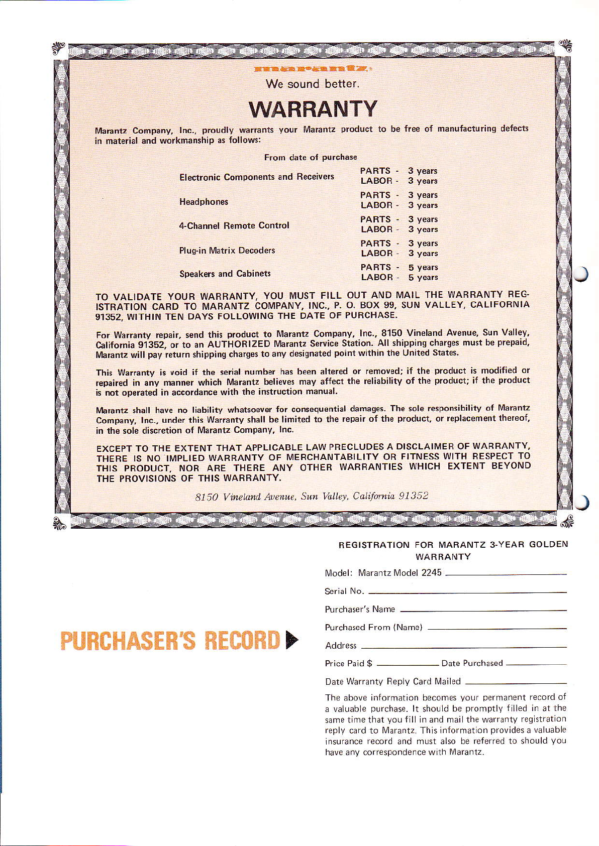
in material and
prosdly
lnc-,
workmanship
WARRANTY
warrants
as lollows:
Elt,seE.üaürgüEr
We sound
your
From
date
betler.
Maränlz
oI
Purchase
prodüct
io be free o{
manulacturins defects
Erectroniccomponenrsa'dReceive's
+Channd Remote
Pluq-in Matrix Decodeß
Speakeß and
TO VALIDATE
ISTRATION CARD
91352.
For Wanänty repair,
California
lvläEntz will
This Wärranty is
repair€d in any
WITHIN TEN DAYS
YOUB WARRANTY,
TO MAFANTZ
send this
91?52, or to an
pay
shipping charges
return
void if the terial
manner which
AUTHORIZED
k not op€räted in aeoldance
l/brantz shall have
Comp.ny, Inc,,
in rhe sole diicrerion
EXCEPT
THERE
TO THE EXTENT
IS NO III/IPLIED
THIS PRODUCT,
THE PROVISIONS
no liability whätsoever
under this Wairanty
ot [4arantz
WARRANTY
NOR ARE THEBE
OF THIS WABRANTY.
Control
Cabinets
YOU MUST
COMPANY,
FOLLOWING
Ploduct
nümber has been
Marantz believes
with the
THE DATE OF
Maran? Companv,
to
Mamnlz Service
ro anv d6iqnated
insttuction
lor consequentiäl
shall be limited
company,
THAT APPLICABLE
lnc.
OF IIIERCHANTABILITY
ANY OTHEB
iääH: :I:i:
PARTS
LABOR
PARTS ' 3
LABOR
PARTS - 3
LABOR
PARTS
LABOB
FILL OUT
P. O. BOX 99. SUN VALLEY,
INC.,
mav aff€ci
manual.
to the
LAW PBECLUDES
PURCHASE.
lnc., 8'150 Vineland
Station.
within the United
Point
altered
or removed; if the
the reliabilitv of the
damages.
tePair oI the
WARBANTIES
.
3
veaß
years
-
3
years
years
-
3
yeals
yeaß
-
3
years
-
5
y€aß
-
5
AND IVIAIL THE
All shippinq charges
States.
Product
product;
The sole resPonsibilitv
product,
DISCLAIMER OF
A
FITNESS WITH
OR
or
WHICH EXTENT
WABRANTY
CALIFORNIA
Avenue,
must be
BEG'
Sun Vallev,
prepaid,
is mddilied
product
iI the
o{ Marantz
teplacement thereoi
WARRANTY,
RESPECT
TO
BEYOND
or
,nitffi
piiE#\$fl
81 50 Vineland. ,$tetue.
fd'$i $ifi
fi$iFiII >
Sun Valle./, Califltnio 91352
REGISTRATION
lvlodel:
Serlal
Purchased
Date
The above information becomes
a valuable
same time that
reply
lnsuränce
häve any correspondence wirh
Marantz IVlodel 2245
No-
From
Wardnty Replv
purchase.
cärd to t\,4arantz. Thls information
record
FOR MARANTZ 3.YEAR
WABRANTY
{Name)
Cdrd
lt
fill ln and mai th€ waiianty
vou
must also be referred 1o should
and
l,4ailed
shouLd
yo!r permanent
promptly
be
provides
Maranlz.
GOLDEN
re.ord ol
filied in
reg stratlon
!alüabie
a
at
the
Vou

TABLE OF CONTENTS
Preparation
Rear Panel Connections
Phono
Tape ln
Tape Out
Auxiliary
Ouadradial
l\4ain ln and
Loundspeaker Systems
Anlenna Attenuator
Power Connections
Connection to
Convenience Outlet
Simplif ied Operating
Tuning
Tuning
l\4ono Switch
Tape lMonitor
Loudness
Low
Filter Switch
Hi
l\4uting Switch and
for
Use
Pre
AC
lvleters
Switch
Switch
Filter Switch
Out
Outlet
Procedure
Level
Control
l\,4uting Circuit
Selector Switch
2
2
2
2
2
3
3
3
3
4
5
5
5
5
6
6
6
6
6
6
6
6
Tape Signals
Tape l\4onitor
Phqno Signals
I\4ono Functions
Switch
Control Circuits
Balance Control
Volume Control
Tone Ampli{ier
Hi-Lirw Filter
Output Stage and Protective
Technical Specificataons
Typical Per{ormance
Service
Note
Curve
Circuits
12
12
12
13
13
13
14
14
15
15
15
16
17
19
Controls and Switches
lVIain
Selector
Balance Control
Volume
Bass
lVIain-Spkr Remote Switch
Front
Switch
Control
l\4id and Treble Controls
PanelJacks
Dubbing Out
Dubbing ln
Stereophones
Suggestion on Using Tape Recorders
Some
with Your
Recording and
Becording
Playback
lMaa<ing Two
Becording a
Copying and
Convertinq
Model 2245
Playback
Recordings Sirnultaneously
Long'Duration Program
Editing
Your
Stereo System to
4 channel
Technical
General
Description
Functional Description
End
Front
lF Stages
Lim iter
FM Stereo Demoduläror
11
11
11
11
12
12
12
1
7
7
7
7
7
8
8
8
8
I
8
8
I
I
LIST OF
1. Rear Panel Connection Facilities and
Adiustments
2.
Loudspeaker System Connectlons
3.
Fl\4/A[\4 Antenna Conneclion
4.
5.
6.
7.
8.
Ferrite-rod
AIVI
Panel
Front
Stereophone Plug
Arrangement oJ Two Tape Becorder
Connection Diagram
Functional Block Diagram
10.
PhonoEqualizationCharacteristics
Tone Control
11.
Low and High Filter
12.
13.
FlVi Characteristics
14.
Stereo Separation
15.
Harmonic Di$ortion
16.
Frequency Response
17.
Päckinq lnstructions
ILTUSTRATIONS
2
3
4
Antenna 5
Controls and Jacks 1
I
I
10
1'l
13
Characteristics 14
Characteristics 14
17
17
18
'18
1S
F{3HüWffiMM
For optimum
l\,4odel 2245 Sleteo
Vour
these instructions
lion are
fpatu'es
controls
This
covers installation
non-technical
2245 in mote detail
Junctional explanations,
discl]ssions.
For
connections,
boldface
and
deserve
and connections.
manual
quick
panels
rear
performance and enjoyment
carefLllly.
not complicated,
yoL/
beLomlrg
is divided
and
lanqllage.
with
identification
references to
exacrly as
type,
Your
Receiver-
o{
Receiver,
lnstallation
but its
into two
operation
second
The
technical
and special
the controls
of
them
thev appear
please srudy
and
flexibility
ldnrllal
parts
wlth
The
in
describes
specifications,
application
printed in
are
the
on
from
opera
and
ils
first
simple,
the
and
fronl
ru ffi ffi A{-
ffi
ffi
lMarantz Model
Your
incorporates
l\4arantz
ind!rstry.
Unparalleled
this combination
ble
sections
Power Amplifier.
and
tween
per{orrnance from each
these
flexibility
ordinary
the advanced
is famous
technology
a single
on
cornponent
o{ separate
flexibility
the connection
headphones;
ers;
additional
solrnd
capabilities
or two recorders.
luner
source.
are included
mffi s#ft
chassis:
o{
two srereo
of:
a lurntab
(such
Record,
I rT'!f-}p$
2245 all solid
circuitry
in the
and innovation
of three
lnternal
sections
section,
components-
your
as SW
audio component
superb
Tuner,
connections
ensure
and retain
l\,4odel
pairs
or record changer;
e
or LW)
pLayback,
{or
lape
a
recelver
state
which
for
possi
made
component
Preamplifier,
be-
optirnum
full
the
extra-
The
permits
2245
loudspeak'
of
an
ä TV
and
copying
and
playback deck
AFTER
advisäble to save all original
It is
prevent
to
the Receiver
ship
instructionsl.
Please
signs of
stringenl
to
operating condition.
inspect
quäliry
packing,
UNPACKING
damage should
(refer
your
darnage in transit. lt has
conTrol
and left the
you
Figure lT for
to
l\,4odel 2245 catelully
inspection dnd
lf the unit is damaged, notify
delay.
Onlv the consignee
carrier
l\4arantz
Save
by the carrier.
for damage during shipment.
Company will cooperate
the damdged carlon as
may institute a claim
evidence
packing
to transport or
wish
undergone
rests
{actory in
the
carrier
However,
{ully in such an
jor
inspeclion
material
packing
Io( aoY
ptiot
perfect
without
with the
the
C
PREPARATION FOR USE
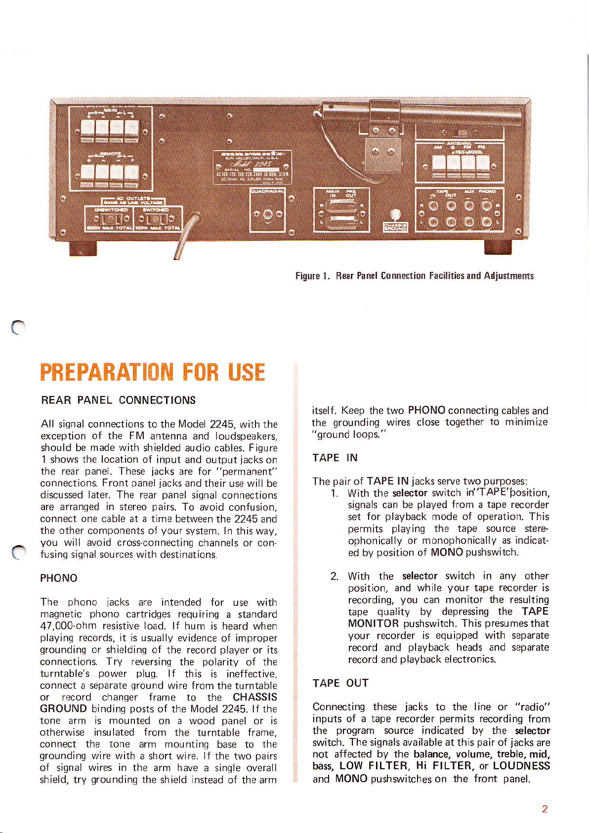
REAR PANEL CONN ECTIONS
All signal connections to the l\4odel
exception of the
$ould be
1 shows
the rear
connections.
discussed
are arranged in slereo
connect one cable at a time
the other
you
fusinq
c
made with
the location
panel.
Front
ldtpr.
components of
wili avoid
siqnal sources
2245, wilh the
Fl\4
antenna and loudspeakers,
shielded audio cables. Figure
of input and output
panel
with
jacks
jacks
panel
pairs.
your
destinations.
for
are
and their use will be
siqndl
To avoid confusion,
between the 2245 and
system. ln this way,
These
The rear
cros+connecting channels or con
jacks
"permanent"
connections
on
Figure l. ßear
Keep
itself.
grounding
the
"ground loops."
TAPE
The
IN
pair
1. Wilh the selector
Panel
C0nnectiofl
the two
o{ TAPE
signals can be
for
set
PHONO
wires close togelher
jacks
lN
played
playback
permits playinq
ophonically or
position
ed by
monophonically as indicat-
of MONO
FacililiesEnd
connecting cables
serve
slvitch
from
mode of operation. This
Ad,ustmeds
and
to
minimire
purposes:
two
irJ'TAPE'bosition,
a tape recorder
the tape sou rce stere
pushswitch.
PHONO
phono jdcks
he
I
magnetrc
47,000-ohm
playing
grounding
connections.
turntable's
connect a separate
phono
resistive load. lf hum is
records, it is usually
or shrelding
Try reversing
power
or record changer frame
GROUND binding
tone arm
otherwise insulated from
is
are intended lor
cartridges requiring
evidence ol improper
ot the record
polarity
the
plug.
ground
lf this is ineffective,
wire from the tLrrntable
to the CHASSIS
posts
of the lModet
mounted on a wood
the turntable
connect the lone arm mounting
grounding
o{ signal
shield, trv
wire
with d
wires in
grounding
short
wrrp. ll
the arm have
lhe shield instedd
a
with
use
a standard
heard when
prayer
or
oJ the
2245.
panel
base to the
thc t!1,o
single overall
tf the
or is
frame,
pars
ol the drrr
its
2. With the
position,
recording,
tape
MONITOB
your
record and
record and
TAPE
Connectinq these
inputs of a tape recorder
the
switch. The signals available at this
not affected
bass,
and
OUT
program
LOW FILTER, Hi FILTER.
lvlONO
pushswitches
selector switch in any other
and while
you
quality
pushswitch.
recorder is
playback
playback
iacks
source
by
the balance.
your
can monitor the resulting
bv depressing the TAPE
This
equipped with
heads and
electronics.
to the line or "tadio"
permits
indicated
volume, treble,
on the
recorder
tape
presumes
recording from
that
separate
separate
by the selector
pair
or
front
jacks
of
LOUDNESS
panel.
are
mid,
is
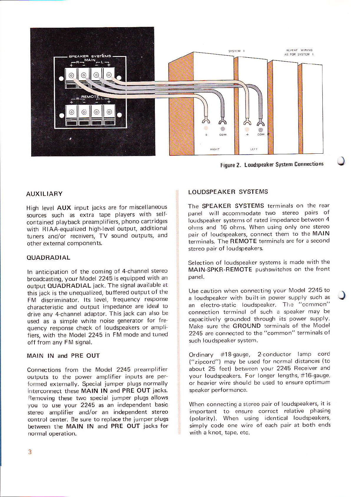
Figure 2.
Loudsteaker
System
Connections
AUXILIARY
level AUX input
High
sources such
contained
as extra
playback
wilh RIAA equalized
t!ners and/or
external components.
other
receivers, TV
iacks
preampl
high-level
OUADBADIAL
ln anticipation
broadcastinq,
ourpur
this
Fl\,4 discriminator.
characteristic
drive
used as a simple
quency
fiers, with the
off from any
OUADRADIAL
jack
is the unequalized,
anv 4 channel
response
of rhe coming
your
l\lodel 2245
jack.
lts level,
output
and
adaptor.
white
check of
lvlodel 2245
FM signal.
MAIN lN and PRE OUT
Connections Jrom the
these
vour
power
lvlAlN lN and
two special
2245 as an
lN and
outputs to the
+ormed
interconnect these
Removing
you
stereo
externally. Special
10 use
amplifier and/or
control center, Be sure
between the MAIN
normal operalion.
are for miscellaneous
players with self
tape
phono
if iers,
output,
sound
outputs,
o{ 4 channel
is equipped
signal available
The
buffered
output
frequency
impedance
jack
This
generator
noise
loudspeakers
in FI\4 mode
l!4odel 2245
amplifier inputs
jumper plugs
PRE OUT
jumper plugs
independent
an independent
to replace the
PRE
iumper
OUT
cartridges
additional
and
stereo
an
with
the
of
response
also be
{re
for
to
are ideal
can
or ampli
tuned
and
preamplifier
per
are
normally
iacks
allows
basic
stereo
plugs
jacks
for
LOUDSPEAKEB
The SPEAKEB
panel
loudspeaker systems
ohms and
pair
terminals.
stereo
Selection
lvlAlN-SPKR-REMOTE
panel.
at
Use
will accommodate
16 ohms. When using
o{ loudspeakers, connect
The REII4OTE
pair
of loudspeakers.
of loudspeaker systems
caution when connecting
a loudspeaker
an electro-static
conneclion
capacitivelv
Vlake sure
2245 are connected
such
Ordinarv #18
("zipcord"i
about
your
or heavier wire
speaker
When
important
(polarity).
simply
with a
the GROUND
loudspeaker system.
25 Jeet) belween
loudspeakers.
performance.
connecting a slereo
code
knot, tape. etc.
SYSTEMS
SYSTEIMS
terminals
Iwo
of rated
with bualt in
loudspeaker,
terminal of such a
qrounded
to the
qauge,
may be
used for normal
For longer
should be used to
to ensure
When
usinq identical
one wire of each
impedance between
them
{erminals are
pushswitches
your
power
through
terminals of
"common"
2 conduclor
your
2245
lengths,
pair
of loudspeakers,
correct relative
on the rear
stereo
only
is made
Tl,e
speaker
its
paars
one stereo
to the
MAIN
for a second
wilh
on lhe
lvlodel
2245 to
supply such
"common"
may be
power
supply.
the Model
terminals
lamp
distances
Receiver
+16
ensure optimum
phasinq
loudspeakers,
pair
at both ends
of
the
front
as
of
cord
(to
and
gauge,
it is
4
J
3
(Note:
'pvaal
rioqF o'
be
wires
channel,
For
Close inspection
\orp
lorr o'codinq o'1 lhp r1'ulatron,4,q,,
g'oovp
"silver"
on ono
while the other
help insure identical connections
each channe.
between the
loudspeaker
amplifier
then connected
and
polarity
l{ there
pairs,
simple
With
with the
C
should
between
centered.
amplifier lerminals.
or if they are
program
and the
channel. The
between the remaininq
phasing
or
is any doubt about
listeninq
signals fed to both channels, and
MONO
appear to originale at a
the loudspeakers,
As the balance contro is turned away
from the center
appear
Room
ambiquous
the
set the controls
listen to
ages. Reverse the
and listen
.ofic"obly
change
ranqement.
the wires connected in reverse,
These
stereo
REMOTE.
to move toward one
acoustics can somelimes
or confusing.
loudspeakers as c ose toqether
program
to the same
less b"\s w l I'
the connections back to the original ar
lf there is noticeably more bass,
phasinq procedures
pair
of
lf both
the sanre listening
peir
is also
"in phase"
wrrp"
Coded
will
näy
of
pouo.
is
ständard
zipcord
onp o
bare copper.)
ll'F
for each
the coded wire can be connecred
"commoi"
GROUND terminal of the
termjnal of
remaining uncoded wire is
Loudspeaker
your
This insures correct
o{
identical
not
test
can
pushswitch
position,
for
balanced
material with strong
wires to one of the loudspeakers
Loudspeakers, whether IMAIN or
pairs
of loudspeakers are used in
area, ensLrre that the [4AlN
loudspeakers.
phasing
identical
verify correct
depressed, the sound
with
the sound source
o{ loudspeaker
loudspeakers, a
point
balance control
the
phasing.
midway
shou d
of the Loudspeakers.
make this test
lf so, lemporari
possible.
as
IMONO operätion and
passage
should be used with each
with
again- lf there is
c
'Fvp
'ad
the REMOTE
y
rnove
Then
pass
bass
,
orn"cr:on.
leave
pair.
(An
shielded
wire can
can cancel
ä1'pr1a.) Lolv
300ohm cable.
act as än omnidirectional antenna,
the directional benefits of
los.300.ol_Tl \'
of two inner conductors
insulating
effectively
multipath distortion.
For rural
dealer be
lightning
system
jacket.
prevents
areas, it is recommended that a loca
consulted about antenna installation and
arrestor
are not recommefded
Model 2245; such systems are
expressly
suppress
addition,
limit
{or television
FM siqnals before distribution. ln
rnaster antenna systems
qLrality
good
This type of shielded cabe
lead-in from
the
protection-
reception
FIVI
reception.
Where ouldoor antennas
inconvenient,
"rabbit
{olded dipole anterrna supplied
2245.
results in
Receiver
antenna.
Aarh are
use a simple
antenna or the simple
ear"
practical
primarv
siqnal
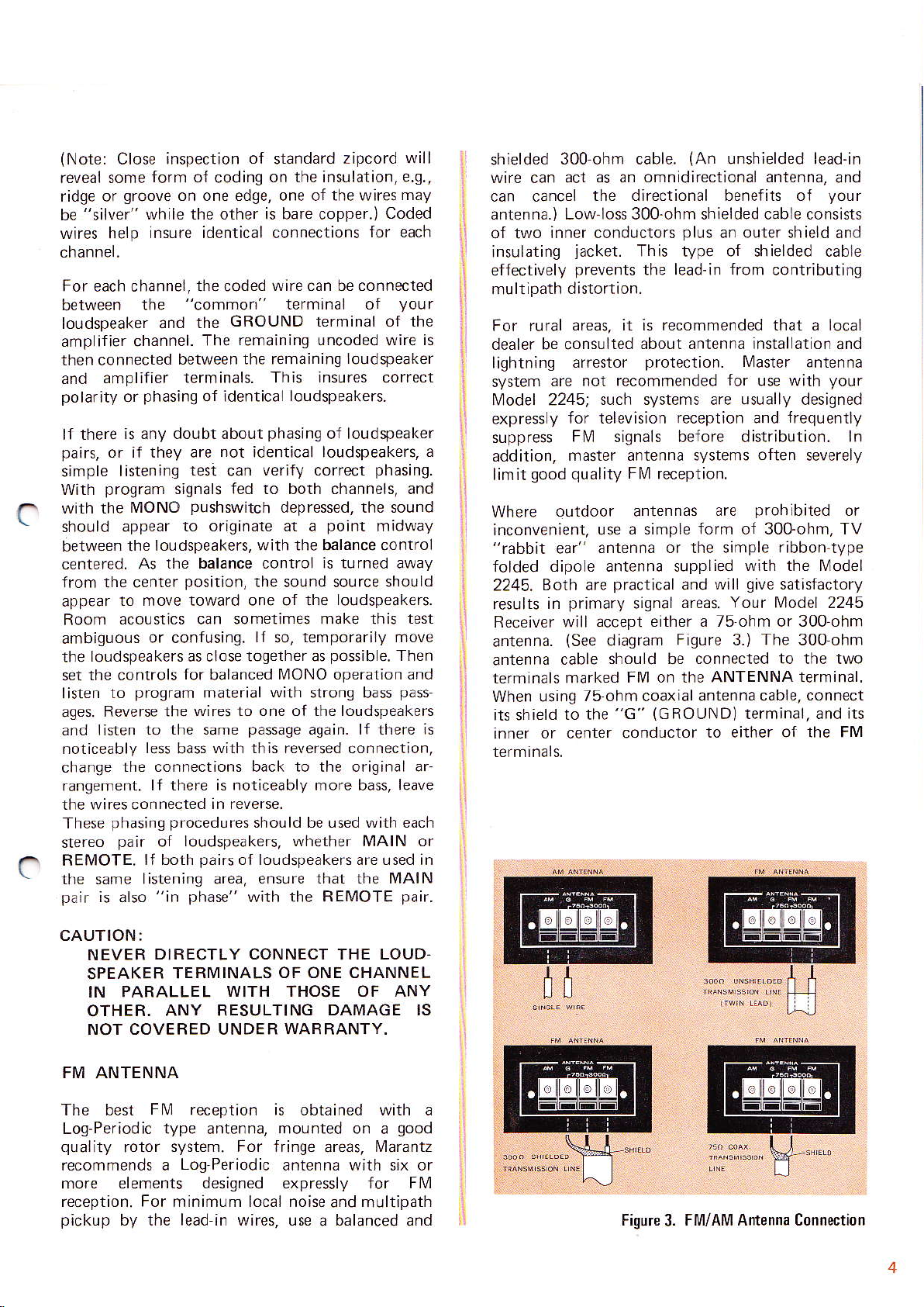
will accept either a 75 ohm or 300 ohm
(See
diagram
Figure
unshielded lead-in
eld"d cdb'p
plus
an ouler shield and
I\,4aster
{or
use with
usually
and
often
prohibited
are
form
of 300-ohm, TV
with the lvlodel
änd will
areas.
qive
Your [,4odel
The
3.)
inrenna cable should be connecled
terminals marked
When using
its sh;eld
to the
FIM on the
75 ohm coaxial
(GROUND)
"G"
inner or center conductor
ANTENNA terminal.
antenna cable, connect
terminal, and its
to either
and
your
or\,sls
'
contributifg
antenna
your
designed
frectuently
severely
or
ribbon
satisfactory
type
2245
300ohm
to
the two
of
the
FM
CAUTION:
NEVER
SPEAKER
IN
OTHER. ANY RESULTING
NOT COVER ED UNDE R
DIRECTLY CONNECT THE LOUD
TERIV]INALS OF ONE CHANNEL
PARALLEL WITH THOSE OF ANY
DAMAGE IS
WARRANTY.
FM ANTENNA
The best
Log-Periodic
quality
recommends a
F [/] reception
type
antenna,
is obtained with a
moLnted
on a
qood
rolor system. For fringe areäs, I\4arantz
Log Periodic
antenna with six or
more elements designed expresslV Jor FM
reception. For minimum local noise
picl<Lrp
by the lead in wires, Lrse a balanced änd
and
multipath
üü
Fiqure
Fl',4/A[4 Antenna Connection
3.
 Loading...