

Marantec EX-2005, EX-2007 Instructions Manual
Access Systems
Automatically The Best Choice
Marantec America Corporation
675 Heathrow Drive Lincolnshire, IL 60069 U.S.A.
Phone 1-888-622-2489 • Fax 847-478-0348
www.marantecamerica.com
Garage Door Opener System
Installation and Operating Instructions
Deluxe EX-2005
Elite EX-2007
Digital Intelligence for the Garage

OWNER’S MANUAL CONTENTS
1. INTRODUCTION . . . . . . . . . . . . . . . . . . . . . . . . . . . . . . . . . . . . . . . . . . . . . . . . . . . . . . . . . . . . . . . . . . . . . . 2
2. ADVANCED FEATURES . . . . . . . . . . . . . . . . . . . . . . . . . . . . . . . . . . . . . . . . . . . . . . . . . . . . . . . . . . . . . . . . . 2
3. IMPORTANT SAFETY INFORMATION . . . . . . . . . . . . . . . . . . . . . . . . . . . . . . . . . . . . . . . . . . . . . . . . . . . . . . 3
4. TOOLS . . . . . . . . . . . . . . . . . . . . . . . . . . . . . . . . . . . . . . . . . . . . . . . . . . . . . . . . . . . . . . . . . . . . . . . . . . . . .4
GARAGE . . . . . . . . . . . . . . . . . . . . . . . . . . . . . . . . . . . . . . . . . . . . . . . . . . . . . . . . . . . . . . . . . . . . . . . . . . . .4
5.
6. OPENER PACKAGE CONTENTS . . . . . . . . . . . . . . . . . . . . . . . . . . . . . . . . . . . . . . . . . . . . . . . . . . . . . . . . . . . 6
INSTALLATION STEPS . . . . . . . . . . . . . . . . . . . . . . . . . . . . . . . . . . . . . . . . . . . . . . . . . . . . . . . . . . . . . . . . . 7
7.
8. OPENER PROGRAMMING . . . . . . . . . . . . . . . . . . . . . . . . . . . . . . . . . . . . . . . . . . . . . . . . . . . . . . . . . . . . . . 15
9. TRANSMITTERS . . . . . . . . . . . . . . . . . . . . . . . . . . . . . . . . . . . . . . . . . . . . . . . . . . . . . . . . . . . . . . . . . . . . . 26
10. OPERATION OF YOUR OPENER . . . . . . . . . . . . . . . . . . . . . . . . . . . . . . . . . . . . . . . . . . . . . . . . . . . . . . . . . . 27
11. TEST SAFETY REVERSAL . . . . . . . . . . . . . . . . . . . . . . . . . . . . . . . . . . . . . . . . . . . . . . . . . . . . . . . . . . . . . . 27
12. TENSION ADJUSTMENT . . . . . . . . . . . . . . . . . . . . . . . . . . . . . . . . . . . . . . . . . . . . . . . . . . . . . . . . . . . . . . . 28
13. RAIL LENGTH ADJUSTMENT—FOR PROFESSIONAL USE ONLY . . . . . . . . . . . . . . . . . . . . . . . . . . . . . . . . . . 28
14. RAIL ASSEMBLY . . . . . . . . . . . . . . . . . . . . . . . . . . . . . . . . . . . . . . . . . . . . . . . . . . . . . . . . . . . . . . . . . . . . 29
15. POWER HEAD ASSEMBLY . . . . . . . . . . . . . . . . . . . . . . . . . . . . . . . . . . . . . . . . . . . . . . . . . . . . . . . . . . . . . 30
16. ACCESSORIES . . . . . . . . . . . . . . . . . . . . . . . . . . . . . . . . . . . . . . . . . . . . . . . . . . . . . . . . . . . . . . . . . . . . . . 32
17. EXTERNAL CONNECTIONS . . . . . . . . . . . . . . . . . . . . . . . . . . . . . . . . . . . . . . . . . . . . . . . . . . . . . . . . . . . . . 33
18. TROUBLESHOOTING—FOR PROFESSIONAL INSTALLER ONLY . . . . . . . . . . . . . . . . . . . . . . . . . . . . . . . . . . . 34
19. ERROR MESSAGES . . . . . . . . . . . . . . . . . . . . . . . . . . . . . . . . . . . . . . . . . . . . . . . . . . . . . . . . . . . . . . . . . . . 35
20. TECHNICAL SPECIFICATION . . . . . . . . . . . . . . . . . . . . . . . . . . . . . . . . . . . . . . . . . . . . . . . . . . . . . . . . . . . . 35
21. MAINTENANCE AND ADJUSTMENTS RECORD . . . . . . . . . . . . . . . . . . . . . . . . . . . . . . . . . . . . . . . . . . . . . . 36
1. INTRODUCTION
Congratulations on purchasing your Marantec®Professional Series Garage Door Opener System, the most innovative opener available today. This stylishly designed digital opener with a wide range of accessories is engineered to provide the smoothest, quietest and safest operation to compliment any home. Advanced
technology results in the opener being capable of easily moving almost any properly balanced residential
garage door, and at the same time providing state-of-the-art safety features to detect obstructions and to
stop and reverse the door, thus helping to protect persons and property near the door.
2. ADVANCED FEATURES
This opener includes numerous state-of-the-art features to provide you, the user, with years of
trouble-free, convenient, and safe use of your automatic garage door opener.
■ Precision Controlled DC Motor, Complete with Automatic Soft Start and Soft Stop Feature:
The opener automatically detects when your door is almost fully closed or fully opened, and gradually slows
the door down before it reaches its fully closed or opened position. During start-up, the door starts moving
slowly and gradually ramps up to full speed for the full travel of your door. This reduces the possible
damaging effects of the sudden starts and stops associated with some other openers, and results in the
smooth operation and increased life of your door and hardware.
■ Built-In Safety Features: Including patented drive system that delivers only the optimum power needed to
move your door safely — Every time!
■ Modular Receiver Concept (patented): Plug-in your choice of frequency module.
■ Photo Eye (Infrared) Safety System: State-of-the-art infrared beam system helps detect obstructions in
the path of your door and automatically reverses closing door travel, helping to protect persons and
property near the door.
2

3. IMPORTANT SAFETY INFORMATION
This manual is essential to the safe and pr
oper installation, operation, and maintenance of your opener. Read
and follow all guidelines and operating instructions before the first use of this product. Store the manual in a
safe, easily accessible location.
IMPORTANT SAFETY INSTRUCTIONS
TO REDUCE THE RISK OF SEVERE INJURY OR DEATH:
1. READ
2.
3.
4.
5.
6.
7. KEEP GARAGE DOORS PROPERLY BALANCED. See Garage Door
8.
AND FOLLOW ALL INSTRUCTIONS CAREFULLY.
Never let children operate or play with door controls. Keep the remote control away
om children.
fr
Always keep the moving door in sight and away from people and objects until it is completely
closed.
NEVER GO UNDER A STOPPED, P
Test door opener monthly. The garage door MUST reverse on contact with a 40mm (1-1/2") high
object on the floor
Failur
If possible, use the emergency release only when the door is closed. Use caution when using this
r
sever
balanced door could cause severe injury or death. Have a qualified service person make repairs to
cables, spring assemblies, and other har
Disconnect the electrical power to the garage door opener before making any repairs or removing the housing cover
NO ONE SHOULD CROSS THE PATH OF THE MOVING DOOR.
ARTIALLY OPEN DOOR.
. After adjusting either the force or the limit of travel, retest the door opener.
e to adjust the opener properly may cause severe injury or death.
elease with the door open. Weak or broken springs may allow the door to fall rapidly, causing
e injury or death.
Owner's Manual. An improperly
dware.
.
IMPORTANT INSTALLATION INSTRUCTIONS
1. Check with the door manufacturer to determine if additional reinforcement is required to support the door prior to installation of the garage door opener.
2. Install garage door opener only on a properly balanced garage door. An improperly balanced
door could cause serious injur
cables, spring assemblies, and other har
Remove all ropes and remove or make inoperative all locks connected to the garage door before
3.
installing opener
If possible, install the door opener 2.1m (7 Ft) or more above the floor. Adjust the emergency
4.
release cord so that knob hangs 1.8m (6 Ft) above the floor.
5. Do not connect the opener to source of power until this manual instructs you to do so.
6. Locate the wall control panel or wall button: (a) within sight of door, (b) at a minimum height
of 5 feet above the gr
of the door.
7. The Emergency Release T
8. After installing the opener
40mm (1-1/2”) high object on the floor
.
ound so small children cannot reach it, and (c) away from all moving parts
SAVE THESE INSTRUCTIONS for future safety, adjustment, and maintenance purposes.
y. Have a qualified service person make repairs to garage door
dware before installing the opener.
ag must remain on the emergency release cord.
, test Safety Reversal System. Door MUST
.
reverse when it contacts a
3
Pencil Tape Measure
D
rill and Drill Bits
Adjustable Wrench
Wire Cutters
R
atchet and Sockets
(
1/2”, 7/16”)
Phillips
Screwdriver
F
lat-Tip
S
crewdriver
7
/16”
W
rench
S
tepladder
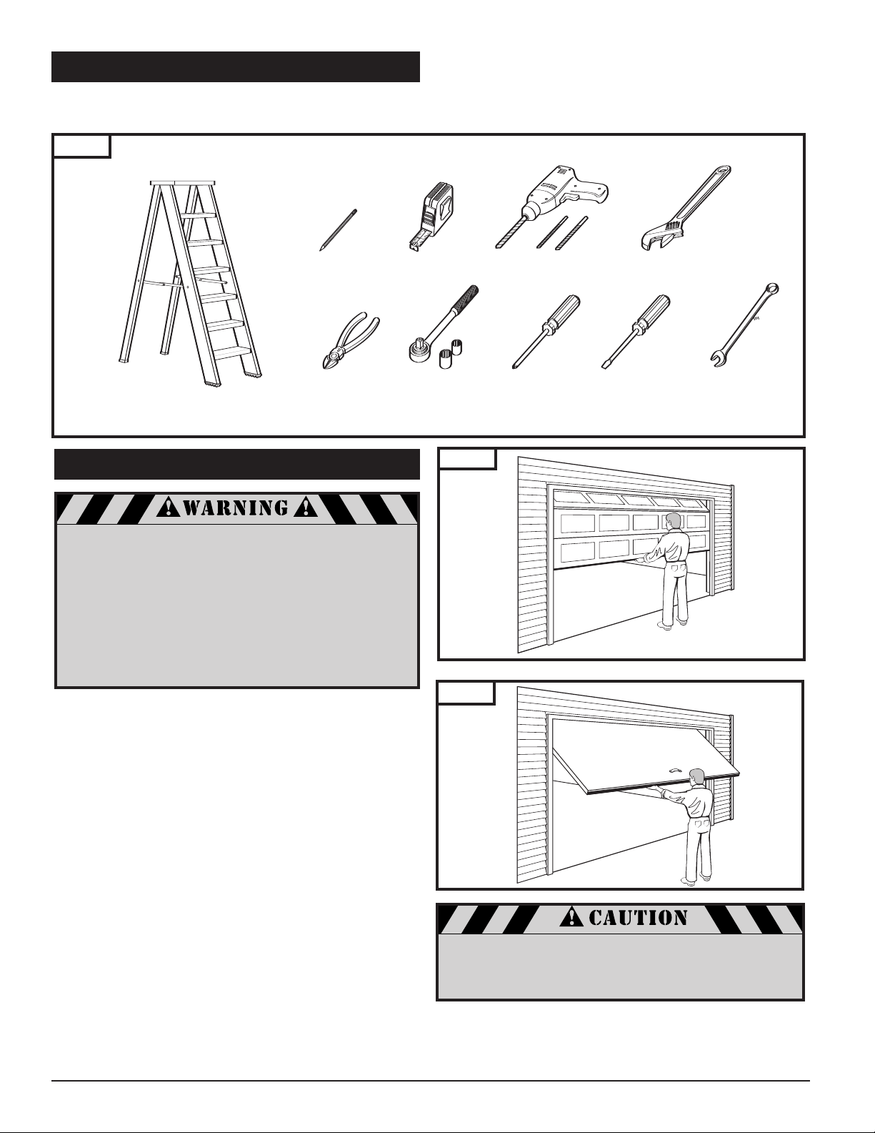
4. TOOLS
One-Piece Door
Sectional Door
The instructions will refer to the tools shown below for proper installation, adjustment, and maintenance of the garage
door opener. Additional tools may be required depending on your particular installation.
Fig. 1
5. GARAGE
A garage door is a heavy moving object and can
cause serious injury or death. An unbalanced door
might not reverse when required, and can increase
the risk of injury. If your garage door is out of
balance, or if it binds or sticks, call for professional
garage door service. Garage doors, springs,
pulleys, cables, and hardware are under extreme
tension and can cause serious injury or death.
Do not try to adjust them yourself. Ropes left
on a garage door could cause someone to become
entangled and could kill them. Remove all ropes
connected to the door before installing your opener.
ake a moment to sur
T
■ Is ther
e an access door besides the garage door? If not,
you should install an emergency key release kit.
■ With the garage door closed, check alignment of door
and garage floor. The gap, if any, should be no more than
5mm (1/4"). If the gap is larger than this, repair floor or
door before installing opener.
■ The opener is intended for installation on a properly
balanced and adjusted garage door. DO NOT INSTALL IF
DOOR IS UNBALANCED OR BROKEN.
■ Check balance of door in mid travel and during full range
of opening and closing. Lift the door about half way,
as shown in Fig. 2 & 3. Release the door. It should remain
in place, supported by its springs. Raise and lower the
door fully to check for binding or sticking.
■ If door is out of balance or needs repair, DO NOT ADJUST
IT YOURSELF. CALL A QUALIFIED GARAGE DOOR SERVICE
PROFESSIONAL to adjust your door.
■ If your door is over 2.1m (7 Ft) high, you will need a
longer rail. See section “6. Rail Assembly" on p. 6 of this
manual for availability of longer rails.
vey your garage and garage door.
Fig. 2
Fig. 3
event damage to steel, aluminum, fiberglass or
o pr
T
glass panel doors, always r
door both ver
tically and horizontally with steel or
angle ir
on bracing.
The best solution is to follow the instr
Sectional Door
One-Piece Door
ce the inside of the
einfor
uctions for your partic-
ular garage door or contact the garage door manufactur
oper reinforcement instructions.
for pr
er
4
5. GARAGE (
Header Wall
Header Bracket
30mm (1-1/4”) Clearance
Highest Point of
Door T
ravel
Door
Distance
Header Wall
1-1/4”
Clearance
Highest Point of
Door Travel
D
oor
H
eader Bracket
D
istance
Header Wall
3-3/4” Clearance
Highest Point of
Door Travel
Door
Jamb
Hardware
Header Bracket
Distance
Header Wall
3-3/4”
Clearance
Highest Point of
Door Travel
D
Door
Pivot
H
eader Bracket
Distance
10' 10"
18"
10' 6 1/2"
14 1/2"
1/2" 1 3/8"
8 1/2"
14 1/2"
cont’d)
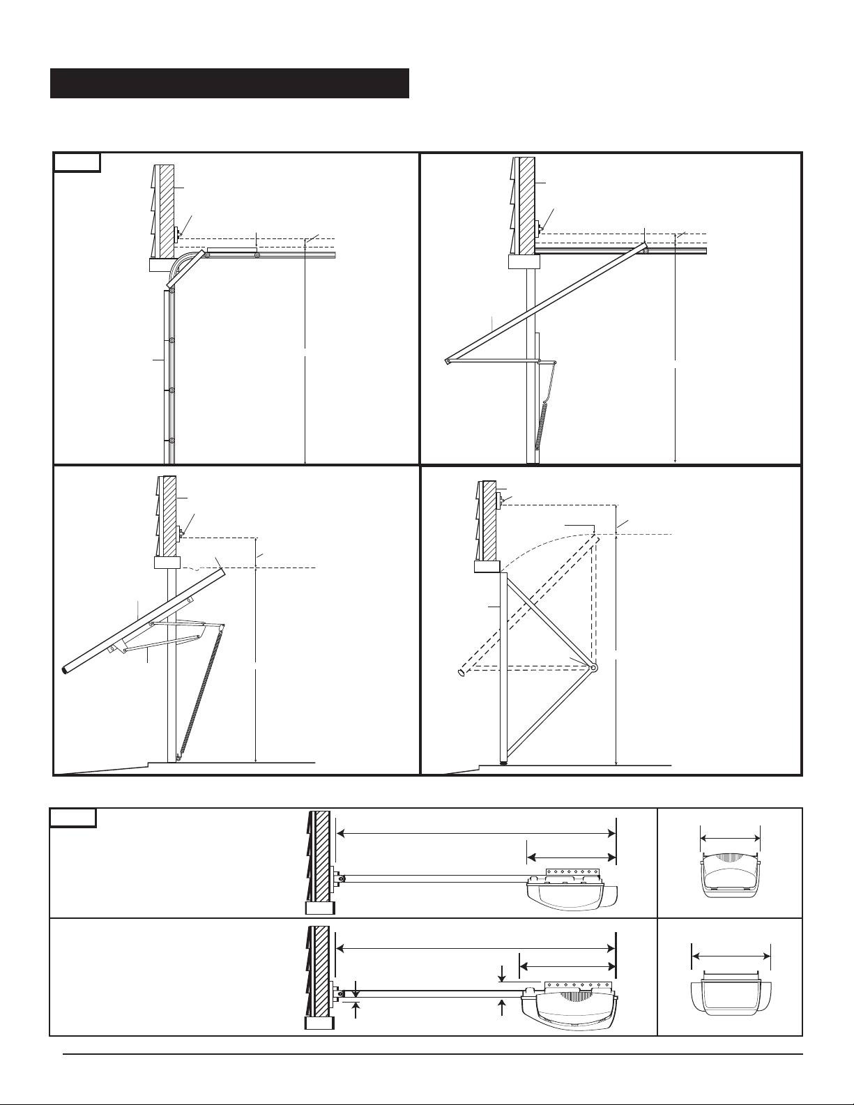
Check the type of door construction you have. The information contained in the figures below will be referred to later
in the manual for pr
Fig. 4
oper installation on the different door types.
Sectional Door
with Curved Track
One-Piece Door
with Jamb Har
e without Track
dwar
with Pivot Har
95mm (3-3/4”)
Clearance
One-Piece Door
with Horizontal T
30mm (1-1/4”)
Clearance
One-Piece Door
dwar
Track
e without
rack
95mm (3-3/4”) Clearance
GARAGE DOOR OPENER SYSTEM OVERALL DIMENSIONS 2.1m (7Ft) DOOR
Fig. 5
One Light Opener
Two Light Opener
3.3m (10’ 10”)
3.2m (10’ 6-1/2”)
460mm (18”)
370mm (14-1/2”)
215mm
(8-1/2”)
370mm
(14-1/2”)
13mm
(1/2”)
35mm
(1-3/8”)
5
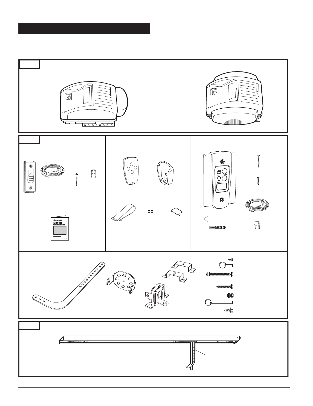
6. OPENER PACKAGE CONTENTS
M-Line
®
S
eries M-4500
(
Power Head with
1
Light Lens)
Hex Head T
“C” Brackets (2)
Curved Door Arm
Door Bracket
Header Bracket
Plastite Screw (4): 6 x 14
Clevis Pin (1): 5/16” x 7/8”
Cotter Ring (1)
Carriage Bolt (2): 1/4”-20 x 2”
Lock Washer (2): 1/4”
Hex Nut (2): 1/4”-20
Lag Screw (2): 5/16” x 1-5/8”
Hex Bolt (2): 5/16”-18 x 3/4”
Lock Nut (2): 5/16”-18
Header Clevis Pin (1): 1/4” x 3-1/4”
Cotter Ring (1)
ek Screw (2): 1/4 x 3/4”
Straight Door Arm
Drywall Anchors (2)
Staples (10)
T
apered-Head Screws
(2)
30 Ft. 2-Conductor
Wire
Screw Caps (2)
Machine screws
(
2)
Warranty
Card
Staples (10)
Round Head Screws (2)
30 Ft. 2-Conductor
Wire
C
over
Programming
Connector
Cover
Visor
Clip
Cover
Programming
The following items ar
e included with your Garage Door Opener. All hardware components located in GDO carton.
The accessories are packaged with their respective hardware in separate packs for ease of identification and use.
Items shown not actual size.
Fig. 6
EX-2005
(One Light
Powerhead)
Fig. 7
Pushbutton
For EX-2005 (with Hardware Kit)
POWERHEADS
ACCESSORIES
9m (30Ft) 2-Conductor
Wire
4-Channel
Mini Transmitter
ransmitter
T
EX-2007
(Two Light
Powerhead)
Wall Control Panel
For EX-2007 (with Hardware Kit)
Mounting Plate
6
Garage Door Opener Manual
Hardware Kit
Fig. 8
Models (per application)
2.1m (7’) Door ML-807B ML-807C
2.4m (8’) Door ML-808B
3m (10’) Door ML-810B ML-810C
RAIL ASSEMBLY
(packaged in separate carton)
Belt
Chain
ML-808C
9m (30Ft) 2-Conductor
Wire
See Fig. 11
See Fig. 10
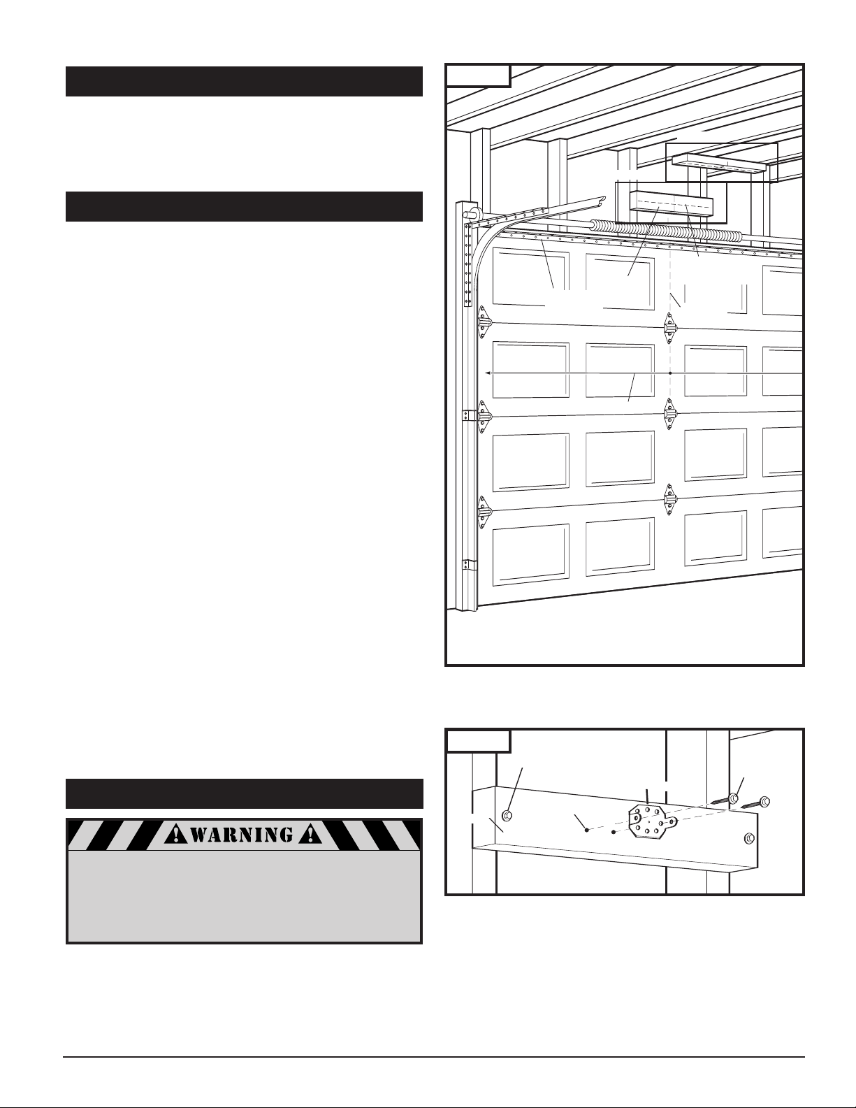
Header
Doo
r Width
V
ertical
Center Line
Horizon
tal Line for
Header Bracket
Height
Horizontal
Reinforcement
Bracket
7. INST
Lag Screw for Header installation
if necessary (not provided)
Header Bracket
5/16 x 1-5/8”
Lag Screw
Pilot Hole
Header
ALLATION STEPS
Identify a sound structural support on header wall above
garage door for header bracket mounting. See Fig. 10. If
appropriate header does not exist, replace or install a new
support using a 50x100mm or 50x150mm (2x4 or 2x6) board.
Fasten it securely using lag screws (not provided) to
structural supports of garage.
7-1. MEASURE AND MARK DOOR AREA
Fig. 9
Before starting your installation, the door and the header
above the door must be measur
opriate brackets can be mounted at the correct locations
appr
avoiding installation and operating dif
ed and marked. This way, the
ficulties later.
MARK VERTICAL CENTER LINE:
■ Measure door width, then locate the center point (Fig.9).
■ Mark
a vertical line on the upper half of your door, on the
top edge of your door
, and on the header, through the
center point.
MEASURE DOOR’S HIGHEST TRAVEL POINT:
(Review Figs. on p. 5 for details)
■ Open door to its highest travel point and measure from
the garage floor to the top of door.
■ Write down this distance.
FOR SECTIONAL DOORS AND ONE-PIECE
DOORS WITH HORIZONTAL TRACK:
Add 30mm (1-1/4") to the door travel height (measured
above).
FOR ONE-PIECE DOORS
WITHOUT
TRACK:
Add 95mm (3-3/4") to the door travel height (measured
above).
MARK HORIZONTAL LINE FOR HEADER
BRACKET LOCATION:
■ Close door and measure the required distance (determined
above)
■ Mark a horizontal line, intersecting the ver
line, on header
from the garage floor to the header.
. This is the position at which the bottom
tical center
of the header bracket should be installed.
■ In case of minimal clearance above the door, the header
bracket may be mounted to the ceiling. In this case,
extend the vertical center line onto the ceiling, and mark
a horizontal line on the ceiling no further than 100mm
(4") from the header wall. The header bracket should be
mounted no farther than this distance from the header
wall.
7-2. INSTALL HEADER BRACKET
Fig. 10
If the header bracket is not rigidly fastened to a sound
structural support on the header wall or ceiling, the
safety reverse system may not work and could cause
serious injury or death. DO NOT move or adjust springs
or garage door hardware, as these parts are under
extreme tension and could cause injury or death.
7
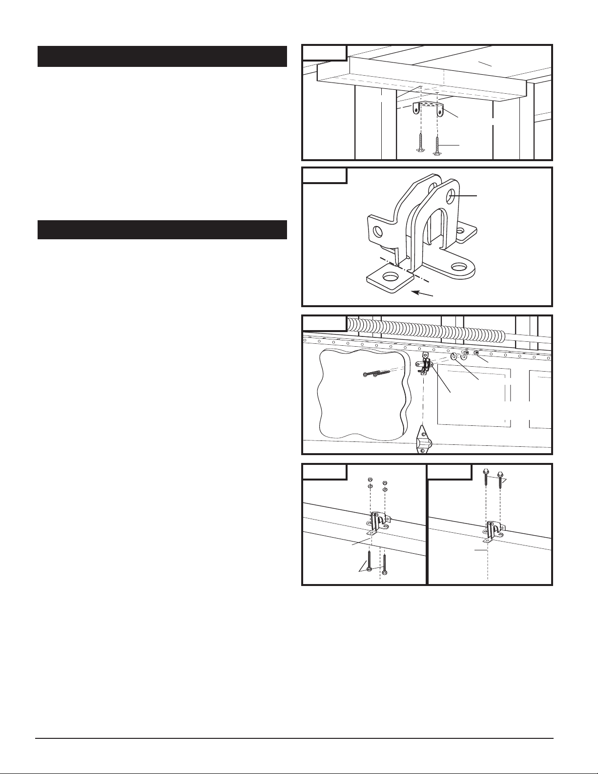
7-2. INSTALL HEADER BRACKET (cont’d)
P
ilot Hole
C
eiling
Header Bracket
L
ag Screw
Insert 1/4-20 x 2”
Carriage Bolts
from outside of door
Door Bracket
Lock Washer
Wood Sectional
Doors
1/4-20 Nut
Garage Door
Center Line
Carriage Bolts
Garage Door
Center Line
Lag Screws
Fig.
11
■ Mark pilot holes location on header thr
lag screws will be inserted.
IMPORTANT: See Fig. 10 for
ough holes where
which header bracket holes to use.
■ Drill 3/16" pilot holes into header, and install bracket with
ews (5/16 x 1-5/8”) provided.
lag scr
■ Tighten lag screws firmly.
NOTE: Follow the same pr
uns vertically instead of horizontally and is the only
11) r
ocedure if header (shown in Fig.
option for mounting header bracket to header wall. In case
of minimal clearance above the garage door, the header
bracket may be mounted to the ceiling. Follow the same
steps above to ensure a sound surface for mounting.
7-3. INSTALL DOOR BRACKET TO DOOR
A. FOR SECTIONAL DOORS:
Wood Sectional Doors (Fig. 13)
■ Position door bracket (Fig. 12) along vertical center line of
door with pin hole facing top of the door and top edge of
the bracket 100mm (4”) to 125mm (5”) below top edge of
the door, or roughly at the same height as top rollers on
the door.
■ Mark locations of securement holes through door bracket.
■ Drill two 1/4" holes through door for securement of
door bracket.
riage bolts (1/4” x 2”) from the outside through
t car
■ Inser
door and bracket, then secur
om the inside.
fr
ighten nuts firmly.
■ T
Metal Sectional Doors
■ Attach door bracket with two teck scr
ecommendations.
door manufactur
er r
e with lock washers and nuts
ews (pr
ovided) per
Fig. 12
Fig. 13
f for one-piece
cut of
door only
Pin Hole
B. FOR ONE-PIECE DOORS:
Befor
mounting leg fr
om opposite side of pin hole.
ting the installation of the door bracket, cut off
e star
One-Piece Doors with Exposed Frames (Fig. 14)
■ Position center of door bracket on the center line on the
top edge of door.
■ Mark the position where carriage bolts will go through
bracket, and drill two 1/4" holes through top frame of
door.
■ Install carriage bolts from the bottom, through door
frame and bracket, and secure with lock washer and nut
from top.
■ Tighten nuts firmly.
One-Piece Doors without Exposed Frames (Fig. 14A)
■ For doors without exposed frames, use alternate method
of mounting door bracket.
■ Mark and drill two 3/16" pilot holes into top of frame,
then secure bracket with 5/16" x 1-5/8" lag screws
(not provided).
8
Fig. 14 Fig. 14A
One-Piece Door
with Exposed Frame:
Install with Carriage Bolts
One-Piece Door
without Exposed Frame:
Install with Lag Screws (not provided)
Correctly seated pin.
Incorrectly seated pin.
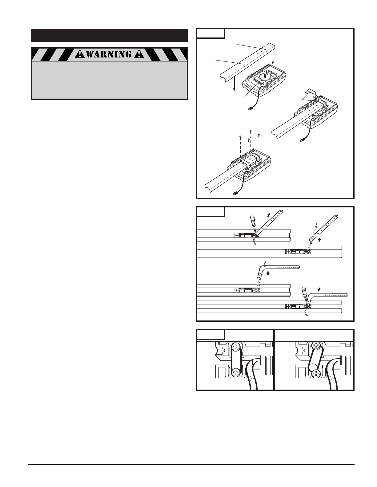
7-4. ATTACH RAIL TO OPENER HEAD
Rail Sprocket
Opening
Rail
Motor Head
Shaft
“C” Brackets
A. Place Rail
onto Chassis
B. Position “C”
Brackets
to Chassis
C. Secure “C”
Brackets
to Chassis
6x14
Screw
A. Loosen Scr
ews
C. Feed Pin through Curved
Door Arm Hole
B. Remove Pin
D. Reinsert Pin and Arm Firmly
and Squarely, Tighten Screws
When fastening the rail to the opener,
use only the screws provided. Use of any
other screws may result in opener falling
from ceiling and causing damage
to persons or pr
NOTE: Rail comes fully preassembled with straight door
arm already attached.
■ Unpack one-piece preassembled rail.
■ Leave straight door arm taped inside rail for safe and
convenient installation—it will be untaped and used later.
■ Position door opener head with control panel facing front
of garage. Rest opener head on cardboard or protective
surface on floor so opener does not get scratched. Chassis
side of opener (with motor shaft sticking out) facing up.
■ Position rail onto opener chassis by lining up rail sprocket
opening with motor head shaft (Fig. 15A). Make sure shaft
engages teeth inside rail sprocket. Press rail down firmly
onto shaft and opener chassis. DO NOT HAMMER.
■ Position 2 "C" brackets over rail and onto chassis. Flanges
on "C" brackets
MUST fit into cutout area on chassis
(Fig. 15B).
■ Insert screws 6 x 14 through bracket holes and into chassis
holes, and tighten screws firmly to hold rail to head
(Fig. 15C).
■ For sectional doors, proceed to step 7-5.
operty in the garage.
Fig. 15
Fig. 16
ADDITIONAL STEP FOR ONE-PIECE
DOORS ONLY:
IMPORTANT NOTE: For installation on One-Piece Doors
only, the straight door arm that is factory installed
onto the rail must be replaced by the curved door
arm supplied as part of hardware in powerhead box.
This must be done after attaching rail to powerhead,
before moving to step 7-5.
■ Turn rail and opener head over so that open channel in
rail faces up.
■ Untape straight door arm that is secured inside rail.
■ Remove and save the two phillips head screws that are
securing the door arm pin and straight door arm (Fig. 16).
■ Lift arm and pin straight out of slot in trolley, and remove
pin from straight door arm.
■ Insert pin into short side of curved door arm as shown.
■ Orient arm so that long side extends away from trolley.
■ Carefully insert pin and door arm into slot in trolley.
Push pin into slot with door arm so pin is fully seated into
trolley slot.
properly into recessed area in trolley. See Fig. 16A.
■ Secure pin and curved arm with the two phillips screws
which were removed from trolley—DO NOT use any
other screws. Tighten screws firmly.
■ Turn rail and powerhead over so that open channel
in rail faces down. Now proceed to Step 7-5.
IMPORTANT: Pin must be straight and seated
Fig. 16A
9
Stepladder
2x4 Laid Flat
Door
Stepladder
Door
Header Bracket
Rail End-Stop
C
otter Ring
1/4 x 3-1/4”
Clevis Pin
Rail
Fig. 17
Fig. 17A
Opener Box
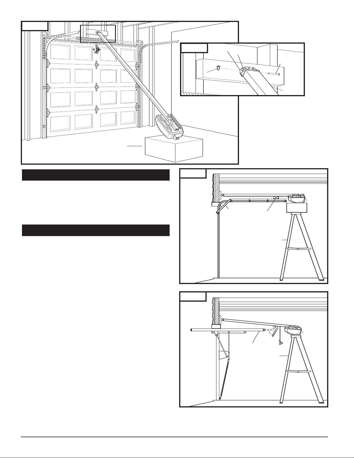
7-5. ATTACH RAIL TO HEADER BRACKET
■ Support opener head slightly off the floor.
■ Lift the opposite end of the rail up to the header bracket.
■ Position rail end-stop within the openings in the header
bracket. Insert header clevis pin (1/4” dia.) through rail
end-stop and header bracket, then attach cotter ring to
end of pin. See Fig. 17A.
7-6. POSITION OPENER FOR MOUNTING
■ Once rail is attached to header bracket, support opener
powerhead on ladder, or use the assistance of another
person to support opener powerhead high enough so
door can open without hitting the rail.
A. SECTIONAL DOORS AND ONE-PIECE
DOORS WITH TRACK:
■ Open garage door to fully opened position, and place a
50mm board between the door and the rail. See Fig. 18.
■ The 2x4 pr
rect mounting height of the opener.
cor
ONE-PIECE DOORS WITHOUT TRACK:
B.
■ Disconnect tr
knob. Move tr
■ Open door all the way so that it is parallel to the floor
or slightly tilted towar
SHOULD NOT BE TILTED TOWARD THE BACK OF GARAGE.
■ Position opener so that top of opener head is level with
top of opened door.
■ To check for correct mounting height, temporarily position
curved door arm as if connecting to door bracket. See
Fig. 19. The long side of the arm should be parallel to the
floor when door is fully opened. Raise or lower
powerhead so that arm will be parallel to floor.
■ Temporarily support head at this height, and prepare to
mount the opener to ceiling.
ovides an easy method of ensuring the
olley by pulling down on emergency release
olley toward opener head.
d the front of the garage. DOOR
,
Fig. 18
50mm board
Fig. 19
10
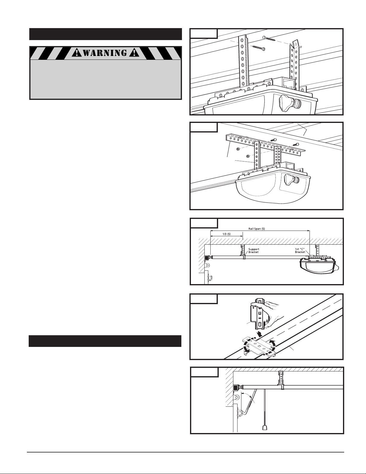
7-7. MOUNT OPENER TO CEILING
Joists (may be
hidden behind
drywall)
Perforated
Angle
Rail
Support
Bracket
Angle
Fig. 20
If not pr
operly secured, the opener
could fall and injure someone.
e opener to structural supports or
Secur
framing. Do not mount to drywall, plaster,
or other such material.
■ Position opener head so that rail is lined up with center
line of open door.
■ Line up hanger brackets (not provided) with ceiling joists
or framing to locate wher
e brackets are to be fastened.
See Fig. 20.
■ Mark location for 5/16" lag screws (not provided), and
drill two 3/16" pilot holes.
■ Fasten hanger brackets to joists using lag screws.
■ If garage framing supports are not visible, attach a length
of perforated angle or a 50mm board to the ceiling, securing it to the hidden joists with lag screws long enough to
fasten firmly to garage framing (extra hardware items not
provided). Then, attach one end of hanger brackets to the
perforated angle or 50mm board mounted to ceiling.
Attach other end of hanger brackets to opener’s chassis
angle iron. See Fig. 21 for alternate mounting methods.
■ Once opener is securely fastened in position, remove
wood blocks and temporary supports and lower door.
Check door for proper operation and clearance by
manually moving door to full open and closed position.
If door hits rail at any point, raise opener head slightly
higher and re-mount in position.
Fig. 21
Fig. 22
NOTE: To provide additional support for rails 13’ length and
longer, use optional support bracket. (Accessories p.32)
■ Measure the rail’s overall span. Bracket is located on 1/3rd
of the overall rail span from the door header bracket end.
See Fig. 22
■ Place support bracket over rail (close side) on a diagonal.
Make sure support securement clamps clear rail sides.
■ Secure bracket onto rail by twisting support bracket as
indicated in Fig. 22A.
■ Attach mounting strap (not provided) to support bracket
and secure by fastening it to the ceiling.
7-8. CONNECT ARM TO DOOR AND TROLLEY
■ Make sure door is fully closed.
■ Remove tape from rail holding straight door arm
(sectional door only) and allow door arm to hang freely.
■ Pull the manual release cord on the trolley to disconnect
trolley from chain or belt connector. Slide trolley to
position it about 100mm (4") away from the door.
Fig. 22A
Fig. 23
11
 Loading...