

Page 1
Access Systems
Automatically The Best Choice
Marantec America Corporation
675 Heathrow Drive Lincolnshire, IL 60069 U.S.A.
Phone 1-888-622-2489 • Fax 847-478-0348
www.marantecamerica.com
Garage Door Opener System
Installation and Operating Instructions
Deluxe EX-2005
Elite EX-2007
Digital Intelligence for the Garage
Page 2

OWNER’S MANUAL CONTENTS
1. INTRODUCTION . . . . . . . . . . . . . . . . . . . . . . . . . . . . . . . . . . . . . . . . . . . . . . . . . . . . . . . . . . . . . . . . . . . . . . 2
2. ADVANCED FEATURES . . . . . . . . . . . . . . . . . . . . . . . . . . . . . . . . . . . . . . . . . . . . . . . . . . . . . . . . . . . . . . . . . 2
3. IMPORTANT SAFETY INFORMATION . . . . . . . . . . . . . . . . . . . . . . . . . . . . . . . . . . . . . . . . . . . . . . . . . . . . . . 3
4. TOOLS . . . . . . . . . . . . . . . . . . . . . . . . . . . . . . . . . . . . . . . . . . . . . . . . . . . . . . . . . . . . . . . . . . . . . . . . . . . . .4
GARAGE . . . . . . . . . . . . . . . . . . . . . . . . . . . . . . . . . . . . . . . . . . . . . . . . . . . . . . . . . . . . . . . . . . . . . . . . . . . .4
5.
6. OPENER PACKAGE CONTENTS . . . . . . . . . . . . . . . . . . . . . . . . . . . . . . . . . . . . . . . . . . . . . . . . . . . . . . . . . . . 6
INSTALLATION STEPS . . . . . . . . . . . . . . . . . . . . . . . . . . . . . . . . . . . . . . . . . . . . . . . . . . . . . . . . . . . . . . . . . 7
7.
8. OPENER PROGRAMMING . . . . . . . . . . . . . . . . . . . . . . . . . . . . . . . . . . . . . . . . . . . . . . . . . . . . . . . . . . . . . . 15
9. TRANSMITTERS . . . . . . . . . . . . . . . . . . . . . . . . . . . . . . . . . . . . . . . . . . . . . . . . . . . . . . . . . . . . . . . . . . . . . 26
10. OPERATION OF YOUR OPENER . . . . . . . . . . . . . . . . . . . . . . . . . . . . . . . . . . . . . . . . . . . . . . . . . . . . . . . . . . 27
11. TEST SAFETY REVERSAL . . . . . . . . . . . . . . . . . . . . . . . . . . . . . . . . . . . . . . . . . . . . . . . . . . . . . . . . . . . . . . 27
12. TENSION ADJUSTMENT . . . . . . . . . . . . . . . . . . . . . . . . . . . . . . . . . . . . . . . . . . . . . . . . . . . . . . . . . . . . . . . 28
13. RAIL LENGTH ADJUSTMENT—FOR PROFESSIONAL USE ONLY . . . . . . . . . . . . . . . . . . . . . . . . . . . . . . . . . . 28
14. RAIL ASSEMBLY . . . . . . . . . . . . . . . . . . . . . . . . . . . . . . . . . . . . . . . . . . . . . . . . . . . . . . . . . . . . . . . . . . . . 29
15. POWER HEAD ASSEMBLY . . . . . . . . . . . . . . . . . . . . . . . . . . . . . . . . . . . . . . . . . . . . . . . . . . . . . . . . . . . . . 30
16. ACCESSORIES . . . . . . . . . . . . . . . . . . . . . . . . . . . . . . . . . . . . . . . . . . . . . . . . . . . . . . . . . . . . . . . . . . . . . . 32
17. EXTERNAL CONNECTIONS . . . . . . . . . . . . . . . . . . . . . . . . . . . . . . . . . . . . . . . . . . . . . . . . . . . . . . . . . . . . . 33
18. TROUBLESHOOTING—FOR PROFESSIONAL INSTALLER ONLY . . . . . . . . . . . . . . . . . . . . . . . . . . . . . . . . . . . 34
19. ERROR MESSAGES . . . . . . . . . . . . . . . . . . . . . . . . . . . . . . . . . . . . . . . . . . . . . . . . . . . . . . . . . . . . . . . . . . . 35
20. TECHNICAL SPECIFICATION . . . . . . . . . . . . . . . . . . . . . . . . . . . . . . . . . . . . . . . . . . . . . . . . . . . . . . . . . . . . 35
21. MAINTENANCE AND ADJUSTMENTS RECORD . . . . . . . . . . . . . . . . . . . . . . . . . . . . . . . . . . . . . . . . . . . . . . 36
1. INTRODUCTION
Congratulations on purchasing your Marantec®Professional Series Garage Door Opener System, the most innovative opener available today. This stylishly designed digital opener with a wide range of accessories is engineered to provide the smoothest, quietest and safest operation to compliment any home. Advanced
technology results in the opener being capable of easily moving almost any properly balanced residential
garage door, and at the same time providing state-of-the-art safety features to detect obstructions and to
stop and reverse the door, thus helping to protect persons and property near the door.
2. ADVANCED FEATURES
This opener includes numerous state-of-the-art features to provide you, the user, with years of
trouble-free, convenient, and safe use of your automatic garage door opener.
■ Precision Controlled DC Motor, Complete with Automatic Soft Start and Soft Stop Feature:
The opener automatically detects when your door is almost fully closed or fully opened, and gradually slows
the door down before it reaches its fully closed or opened position. During start-up, the door starts moving
slowly and gradually ramps up to full speed for the full travel of your door. This reduces the possible
damaging effects of the sudden starts and stops associated with some other openers, and results in the
smooth operation and increased life of your door and hardware.
■ Built-In Safety Features: Including patented drive system that delivers only the optimum power needed to
move your door safely — Every time!
■ Modular Receiver Concept (patented): Plug-in your choice of frequency module.
■ Photo Eye (Infrared) Safety System: State-of-the-art infrared beam system helps detect obstructions in
the path of your door and automatically reverses closing door travel, helping to protect persons and
property near the door.
2
Page 3
3. IMPORTANT SAFETY INFORMATION
This manual is essential to the safe and pr
oper installation, operation, and maintenance of your opener. Read
and follow all guidelines and operating instructions before the first use of this product. Store the manual in a
safe, easily accessible location.
IMPORTANT SAFETY INSTRUCTIONS
TO REDUCE THE RISK OF SEVERE INJURY OR DEATH:
1. READ
2.
3.
4.
5.
6.
7. KEEP GARAGE DOORS PROPERLY BALANCED. See Garage Door
8.
AND FOLLOW ALL INSTRUCTIONS CAREFULLY.
Never let children operate or play with door controls. Keep the remote control away
om children.
fr
Always keep the moving door in sight and away from people and objects until it is completely
closed.
NEVER GO UNDER A STOPPED, P
Test door opener monthly. The garage door MUST reverse on contact with a 40mm (1-1/2") high
object on the floor
Failur
If possible, use the emergency release only when the door is closed. Use caution when using this
r
sever
balanced door could cause severe injury or death. Have a qualified service person make repairs to
cables, spring assemblies, and other har
Disconnect the electrical power to the garage door opener before making any repairs or removing the housing cover
NO ONE SHOULD CROSS THE PATH OF THE MOVING DOOR.
ARTIALLY OPEN DOOR.
. After adjusting either the force or the limit of travel, retest the door opener.
e to adjust the opener properly may cause severe injury or death.
elease with the door open. Weak or broken springs may allow the door to fall rapidly, causing
e injury or death.
Owner's Manual. An improperly
dware.
.
IMPORTANT INSTALLATION INSTRUCTIONS
1. Check with the door manufacturer to determine if additional reinforcement is required to support the door prior to installation of the garage door opener.
2. Install garage door opener only on a properly balanced garage door. An improperly balanced
door could cause serious injur
cables, spring assemblies, and other har
Remove all ropes and remove or make inoperative all locks connected to the garage door before
3.
installing opener
If possible, install the door opener 2.1m (7 Ft) or more above the floor. Adjust the emergency
4.
release cord so that knob hangs 1.8m (6 Ft) above the floor.
5. Do not connect the opener to source of power until this manual instructs you to do so.
6. Locate the wall control panel or wall button: (a) within sight of door, (b) at a minimum height
of 5 feet above the gr
of the door.
7. The Emergency Release T
8. After installing the opener
40mm (1-1/2”) high object on the floor
.
ound so small children cannot reach it, and (c) away from all moving parts
SAVE THESE INSTRUCTIONS for future safety, adjustment, and maintenance purposes.
y. Have a qualified service person make repairs to garage door
dware before installing the opener.
ag must remain on the emergency release cord.
, test Safety Reversal System. Door MUST
.
reverse when it contacts a
3
Page 4
Pencil Tape Measure
D
rill and Drill Bits
Adjustable Wrench
Wire Cutters
R
atchet and Sockets
(
1/2”, 7/16”)
Phillips
Screwdriver
F
lat-Tip
S
crewdriver
7
/16”
W
rench
S
tepladder
4. TOOLS
One-Piece Door
Sectional Door
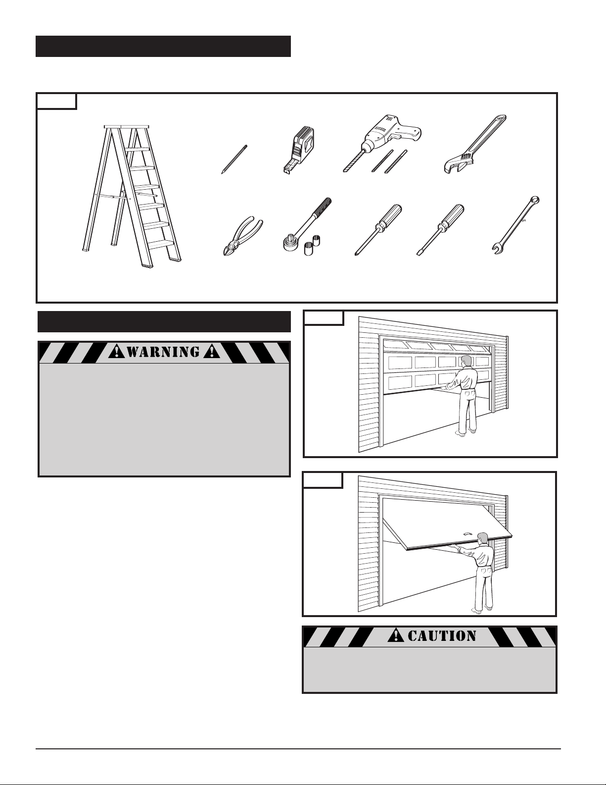
The instructions will refer to the tools shown below for proper installation, adjustment, and maintenance of the garage
door opener. Additional tools may be required depending on your particular installation.
Fig. 1
5. GARAGE
A garage door is a heavy moving object and can
cause serious injury or death. An unbalanced door
might not reverse when required, and can increase
the risk of injury. If your garage door is out of
balance, or if it binds or sticks, call for professional
garage door service. Garage doors, springs,
pulleys, cables, and hardware are under extreme
tension and can cause serious injury or death.
Do not try to adjust them yourself. Ropes left
on a garage door could cause someone to become
entangled and could kill them. Remove all ropes
connected to the door before installing your opener.
ake a moment to sur
T
■ Is ther
e an access door besides the garage door? If not,
you should install an emergency key release kit.
■ With the garage door closed, check alignment of door
and garage floor. The gap, if any, should be no more than
5mm (1/4"). If the gap is larger than this, repair floor or
door before installing opener.
■ The opener is intended for installation on a properly
balanced and adjusted garage door. DO NOT INSTALL IF
DOOR IS UNBALANCED OR BROKEN.
■ Check balance of door in mid travel and during full range
of opening and closing. Lift the door about half way,
as shown in Fig. 2 & 3. Release the door. It should remain
in place, supported by its springs. Raise and lower the
door fully to check for binding or sticking.
■ If door is out of balance or needs repair, DO NOT ADJUST
IT YOURSELF. CALL A QUALIFIED GARAGE DOOR SERVICE
PROFESSIONAL to adjust your door.
■ If your door is over 2.1m (7 Ft) high, you will need a
longer rail. See section “6. Rail Assembly" on p. 6 of this
manual for availability of longer rails.
vey your garage and garage door.
Fig. 2
Fig. 3
event damage to steel, aluminum, fiberglass or
o pr
T
glass panel doors, always r
door both ver
tically and horizontally with steel or
angle ir
on bracing.
The best solution is to follow the instr
Sectional Door
One-Piece Door
ce the inside of the
einfor
uctions for your partic-
ular garage door or contact the garage door manufactur
oper reinforcement instructions.
for pr
er
4
Page 5
5. GARAGE (
Header Wall
Header Bracket
30mm (1-1/4”) Clearance
Highest Point of
Door T
ravel
Door
Distance
Header Wall
1-1/4”
Clearance
Highest Point of
Door Travel
D
oor
H
eader Bracket
D
istance
Header Wall
3-3/4” Clearance
Highest Point of
Door Travel
Door
Jamb
Hardware
Header Bracket
Distance
Header Wall
3-3/4”
Clearance
Highest Point of
Door Travel
D
Door
Pivot
H
eader Bracket
Distance
10' 10"
18"
10' 6 1/2"
14 1/2"
1/2" 1 3/8"
8 1/2"
14 1/2"
cont’d)
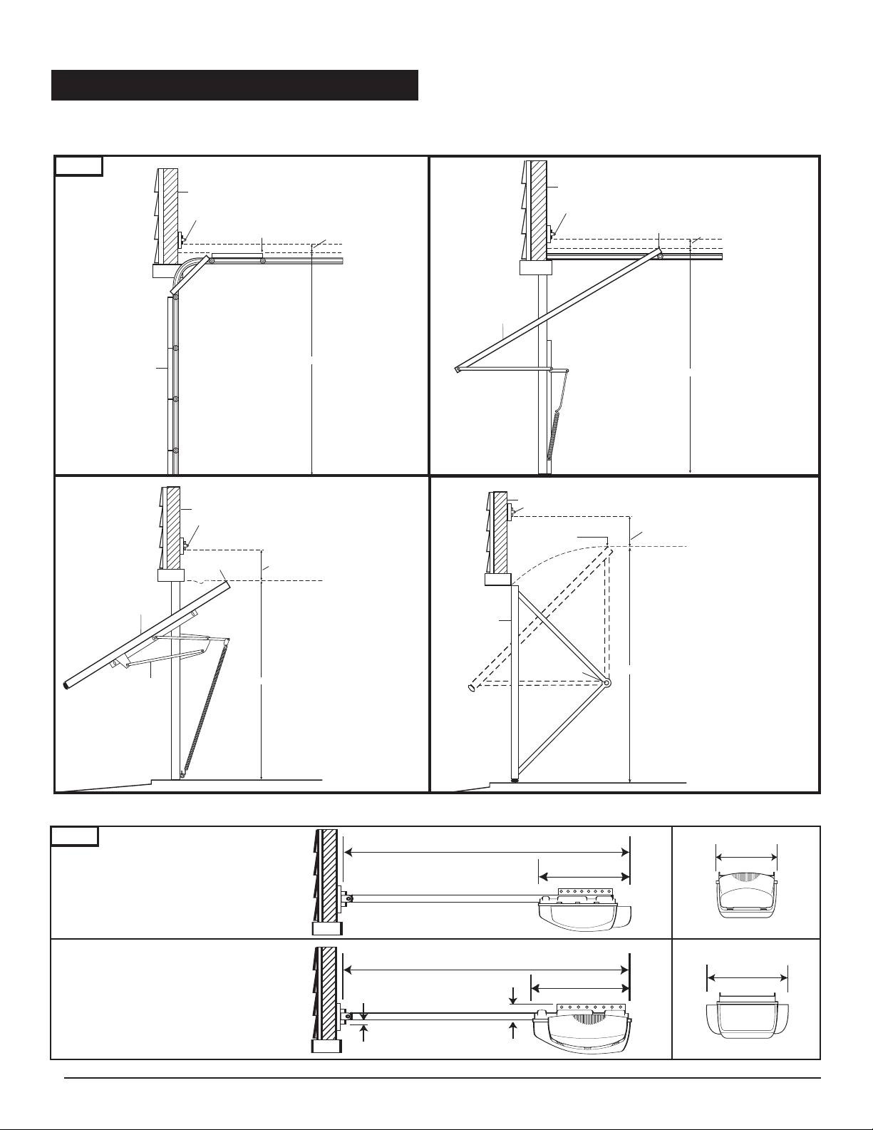
Check the type of door construction you have. The information contained in the figures below will be referred to later
in the manual for pr
Fig. 4
oper installation on the different door types.
Sectional Door
with Curved Track
One-Piece Door
with Jamb Har
e without Track
dwar
with Pivot Har
95mm (3-3/4”)
Clearance
One-Piece Door
with Horizontal T
30mm (1-1/4”)
Clearance
One-Piece Door
dwar
Track
e without
rack
95mm (3-3/4”) Clearance
GARAGE DOOR OPENER SYSTEM OVERALL DIMENSIONS 2.1m (7Ft) DOOR
Fig. 5
One Light Opener
Two Light Opener
3.3m (10’ 10”)
3.2m (10’ 6-1/2”)
460mm (18”)
370mm (14-1/2”)
215mm
(8-1/2”)
370mm
(14-1/2”)
13mm
(1/2”)
35mm
(1-3/8”)
5
Page 6
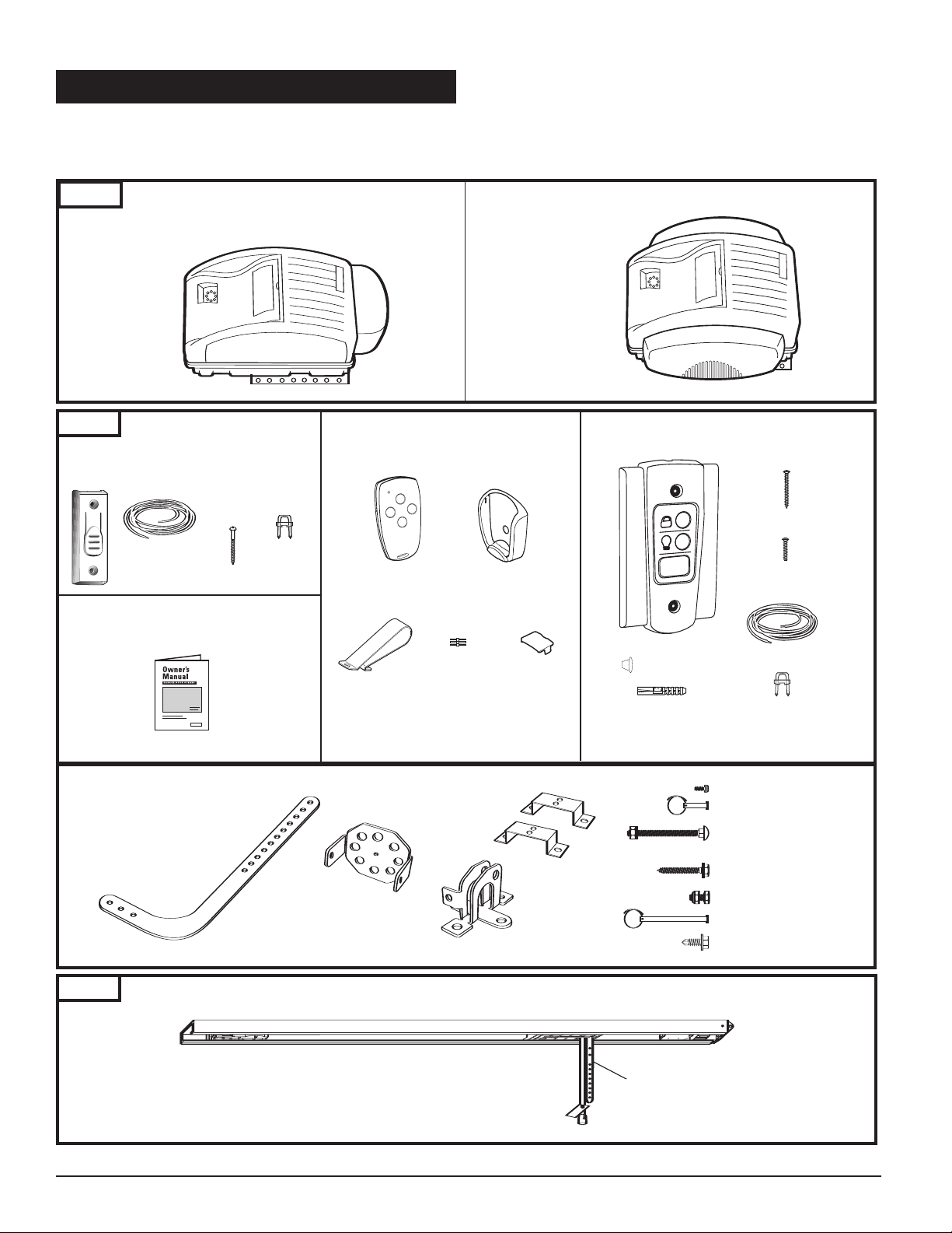
6. OPENER PACKAGE CONTENTS
M-Line
®
S
eries M-4500
(
Power Head with
1
Light Lens)
Hex Head T
“C” Brackets (2)
Curved Door Arm
Door Bracket
Header Bracket
Plastite Screw (4): 6 x 14
Clevis Pin (1): 5/16” x 7/8”
Cotter Ring (1)
Carriage Bolt (2): 1/4”-20 x 2”
Lock Washer (2): 1/4”
Hex Nut (2): 1/4”-20
Lag Screw (2): 5/16” x 1-5/8”
Hex Bolt (2): 5/16”-18 x 3/4”
Lock Nut (2): 5/16”-18
Header Clevis Pin (1): 1/4” x 3-1/4”
Cotter Ring (1)
ek Screw (2): 1/4 x 3/4”
Straight Door Arm
Drywall Anchors (2)
Staples (10)
T
apered-Head Screws
(2)
30 Ft. 2-Conductor
Wire
Screw Caps (2)
Machine screws
(
2)
Warranty
Card
Staples (10)
Round Head Screws (2)
30 Ft. 2-Conductor
Wire
C
over
Programming
Connector
Cover
Visor
Clip
Cover
Programming
The following items ar
e included with your Garage Door Opener. All hardware components located in GDO carton.
The accessories are packaged with their respective hardware in separate packs for ease of identification and use.
Items shown not actual size.
Fig. 6
EX-2005
(One Light
Powerhead)
Fig. 7
Pushbutton
For EX-2005 (with Hardware Kit)
POWERHEADS
ACCESSORIES
9m (30Ft) 2-Conductor
Wire
4-Channel
Mini Transmitter
ransmitter
T
EX-2007
(Two Light
Powerhead)
Wall Control Panel
For EX-2007 (with Hardware Kit)
Mounting Plate
6
Garage Door Opener Manual
Hardware Kit
Fig. 8
Models (per application)
2.1m (7’) Door ML-807B ML-807C
2.4m (8’) Door ML-808B
3m (10’) Door ML-810B ML-810C
RAIL ASSEMBLY
(packaged in separate carton)
Belt
Chain
ML-808C
9m (30Ft) 2-Conductor
Wire
Page 7
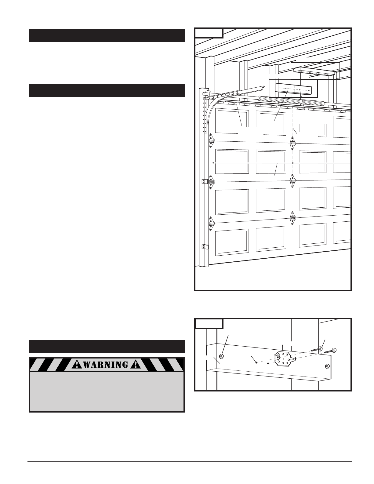
See Fig. 11
See Fig. 10
Header
Doo
r Width
V
ertical
Center Line
Horizon
tal Line for
Header Bracket
Height
Horizontal
Reinforcement
Bracket
7. INST
Lag Screw for Header installation
if necessary (not provided)
Header Bracket
5/16 x 1-5/8”
Lag Screw
Pilot Hole
Header
ALLATION STEPS
Identify a sound structural support on header wall above
garage door for header bracket mounting. See Fig. 10. If
appropriate header does not exist, replace or install a new
support using a 50x100mm or 50x150mm (2x4 or 2x6) board.
Fasten it securely using lag screws (not provided) to
structural supports of garage.
7-1. MEASURE AND MARK DOOR AREA
Fig. 9
Before starting your installation, the door and the header
above the door must be measur
opriate brackets can be mounted at the correct locations
appr
avoiding installation and operating dif
ed and marked. This way, the
ficulties later.
MARK VERTICAL CENTER LINE:
■ Measure door width, then locate the center point (Fig.9).
■ Mark
a vertical line on the upper half of your door, on the
top edge of your door
, and on the header, through the
center point.
MEASURE DOOR’S HIGHEST TRAVEL POINT:
(Review Figs. on p. 5 for details)
■ Open door to its highest travel point and measure from
the garage floor to the top of door.
■ Write down this distance.
FOR SECTIONAL DOORS AND ONE-PIECE
DOORS WITH HORIZONTAL TRACK:
Add 30mm (1-1/4") to the door travel height (measured
above).
FOR ONE-PIECE DOORS
WITHOUT
TRACK:
Add 95mm (3-3/4") to the door travel height (measured
above).
MARK HORIZONTAL LINE FOR HEADER
BRACKET LOCATION:
■ Close door and measure the required distance (determined
above)
■ Mark a horizontal line, intersecting the ver
line, on header
from the garage floor to the header.
. This is the position at which the bottom
tical center
of the header bracket should be installed.
■ In case of minimal clearance above the door, the header
bracket may be mounted to the ceiling. In this case,
extend the vertical center line onto the ceiling, and mark
a horizontal line on the ceiling no further than 100mm
(4") from the header wall. The header bracket should be
mounted no farther than this distance from the header
wall.
7-2. INSTALL HEADER BRACKET
Fig. 10
If the header bracket is not rigidly fastened to a sound
structural support on the header wall or ceiling, the
safety reverse system may not work and could cause
serious injury or death. DO NOT move or adjust springs
or garage door hardware, as these parts are under
extreme tension and could cause injury or death.
7
Page 8
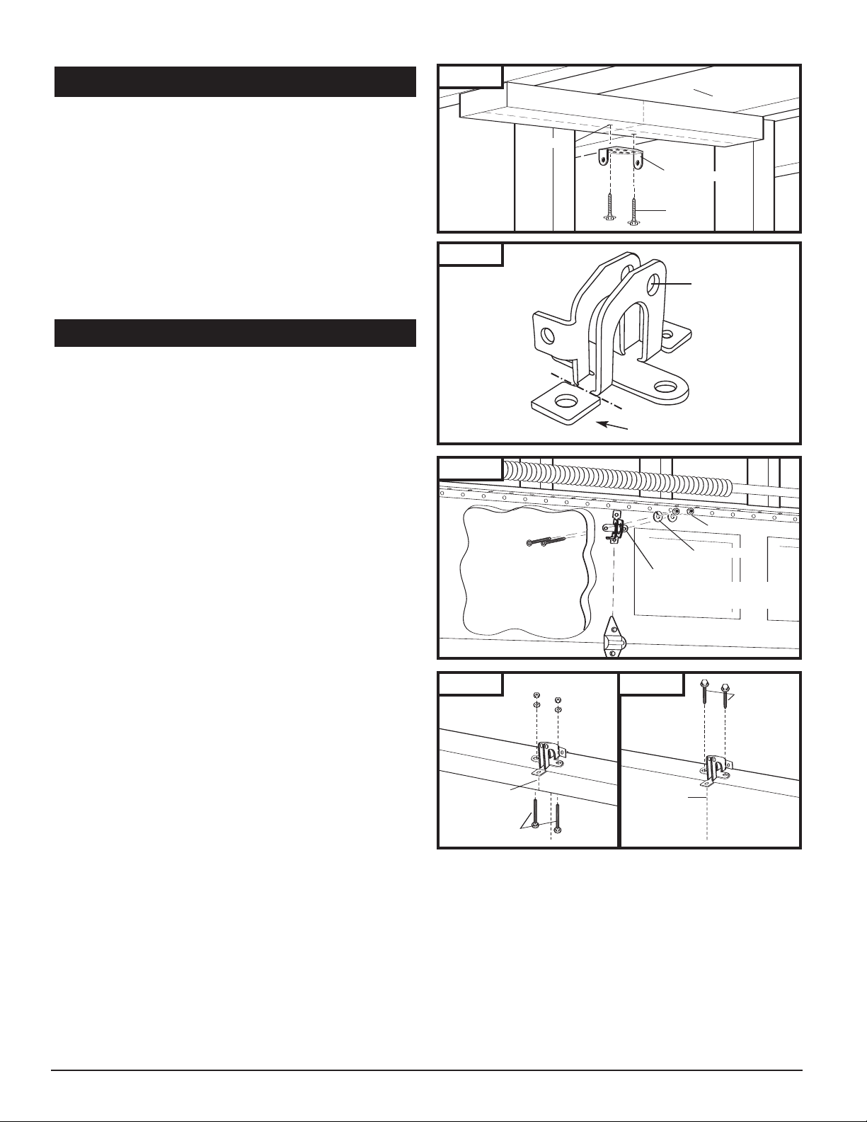
7-2. INSTALL HEADER BRACKET (cont’d)
P
ilot Hole
C
eiling
Header Bracket
L
ag Screw
Insert 1/4-20 x 2”
Carriage Bolts
from outside of door
Door Bracket
Lock Washer
Wood Sectional
Doors
1/4-20 Nut
Garage Door
Center Line
Carriage Bolts
Garage Door
Center Line
Lag Screws
Fig.
11
■ Mark pilot holes location on header thr
lag screws will be inserted.
IMPORTANT: See Fig. 10 for
ough holes where
which header bracket holes to use.
■ Drill 3/16" pilot holes into header, and install bracket with
ews (5/16 x 1-5/8”) provided.
lag scr
■ Tighten lag screws firmly.
NOTE: Follow the same pr
uns vertically instead of horizontally and is the only
11) r
ocedure if header (shown in Fig.
option for mounting header bracket to header wall. In case
of minimal clearance above the garage door, the header
bracket may be mounted to the ceiling. Follow the same
steps above to ensure a sound surface for mounting.
7-3. INSTALL DOOR BRACKET TO DOOR
A. FOR SECTIONAL DOORS:
Wood Sectional Doors (Fig. 13)
■ Position door bracket (Fig. 12) along vertical center line of
door with pin hole facing top of the door and top edge of
the bracket 100mm (4”) to 125mm (5”) below top edge of
the door, or roughly at the same height as top rollers on
the door.
■ Mark locations of securement holes through door bracket.
■ Drill two 1/4" holes through door for securement of
door bracket.
riage bolts (1/4” x 2”) from the outside through
t car
■ Inser
door and bracket, then secur
om the inside.
fr
ighten nuts firmly.
■ T
Metal Sectional Doors
■ Attach door bracket with two teck scr
ecommendations.
door manufactur
er r
e with lock washers and nuts
ews (pr
ovided) per
Fig. 12
Fig. 13
f for one-piece
cut of
door only
Pin Hole
B. FOR ONE-PIECE DOORS:
Befor
mounting leg fr
om opposite side of pin hole.
ting the installation of the door bracket, cut off
e star
One-Piece Doors with Exposed Frames (Fig. 14)
■ Position center of door bracket on the center line on the
top edge of door.
■ Mark the position where carriage bolts will go through
bracket, and drill two 1/4" holes through top frame of
door.
■ Install carriage bolts from the bottom, through door
frame and bracket, and secure with lock washer and nut
from top.
■ Tighten nuts firmly.
One-Piece Doors without Exposed Frames (Fig. 14A)
■ For doors without exposed frames, use alternate method
of mounting door bracket.
■ Mark and drill two 3/16" pilot holes into top of frame,
then secure bracket with 5/16" x 1-5/8" lag screws
(not provided).
8
Fig. 14 Fig. 14A
One-Piece Door
with Exposed Frame:
Install with Carriage Bolts
One-Piece Door
without Exposed Frame:
Install with Lag Screws (not provided)
Page 9
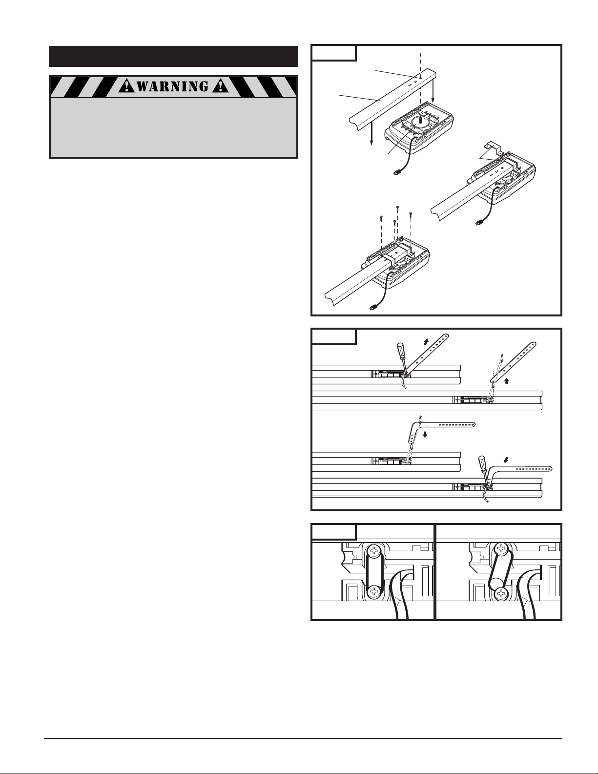
Correctly seated pin.
Incorrectly seated pin.
7-4. ATTACH RAIL TO OPENER HEAD
Rail Sprocket
Opening
Rail
Motor Head
Shaft
“C” Brackets
A. Place Rail
onto Chassis
B. Position “C”
Brackets
to Chassis
C. Secure “C”
Brackets
to Chassis
6x14
Screw
A. Loosen Scr
ews
C. Feed Pin through Curved
Door Arm Hole
B. Remove Pin
D. Reinsert Pin and Arm Firmly
and Squarely, Tighten Screws
When fastening the rail to the opener,
use only the screws provided. Use of any
other screws may result in opener falling
from ceiling and causing damage
to persons or pr
NOTE: Rail comes fully preassembled with straight door
arm already attached.
■ Unpack one-piece preassembled rail.
■ Leave straight door arm taped inside rail for safe and
convenient installation—it will be untaped and used later.
■ Position door opener head with control panel facing front
of garage. Rest opener head on cardboard or protective
surface on floor so opener does not get scratched. Chassis
side of opener (with motor shaft sticking out) facing up.
■ Position rail onto opener chassis by lining up rail sprocket
opening with motor head shaft (Fig. 15A). Make sure shaft
engages teeth inside rail sprocket. Press rail down firmly
onto shaft and opener chassis. DO NOT HAMMER.
■ Position 2 "C" brackets over rail and onto chassis. Flanges
on "C" brackets
MUST fit into cutout area on chassis
(Fig. 15B).
■ Insert screws 6 x 14 through bracket holes and into chassis
holes, and tighten screws firmly to hold rail to head
(Fig. 15C).
■ For sectional doors, proceed to step 7-5.
operty in the garage.
Fig. 15
Fig. 16
ADDITIONAL STEP FOR ONE-PIECE
DOORS ONLY:
IMPORTANT NOTE: For installation on One-Piece Doors
only, the straight door arm that is factory installed
onto the rail must be replaced by the curved door
arm supplied as part of hardware in powerhead box.
This must be done after attaching rail to powerhead,
before moving to step 7-5.
■ Turn rail and opener head over so that open channel in
rail faces up.
■ Untape straight door arm that is secured inside rail.
■ Remove and save the two phillips head screws that are
securing the door arm pin and straight door arm (Fig. 16).
■ Lift arm and pin straight out of slot in trolley, and remove
pin from straight door arm.
■ Insert pin into short side of curved door arm as shown.
■ Orient arm so that long side extends away from trolley.
■ Carefully insert pin and door arm into slot in trolley.
Push pin into slot with door arm so pin is fully seated into
trolley slot.
properly into recessed area in trolley. See Fig. 16A.
■ Secure pin and curved arm with the two phillips screws
which were removed from trolley—DO NOT use any
other screws. Tighten screws firmly.
■ Turn rail and powerhead over so that open channel
in rail faces down. Now proceed to Step 7-5.
IMPORTANT: Pin must be straight and seated
Fig. 16A
9
Page 10
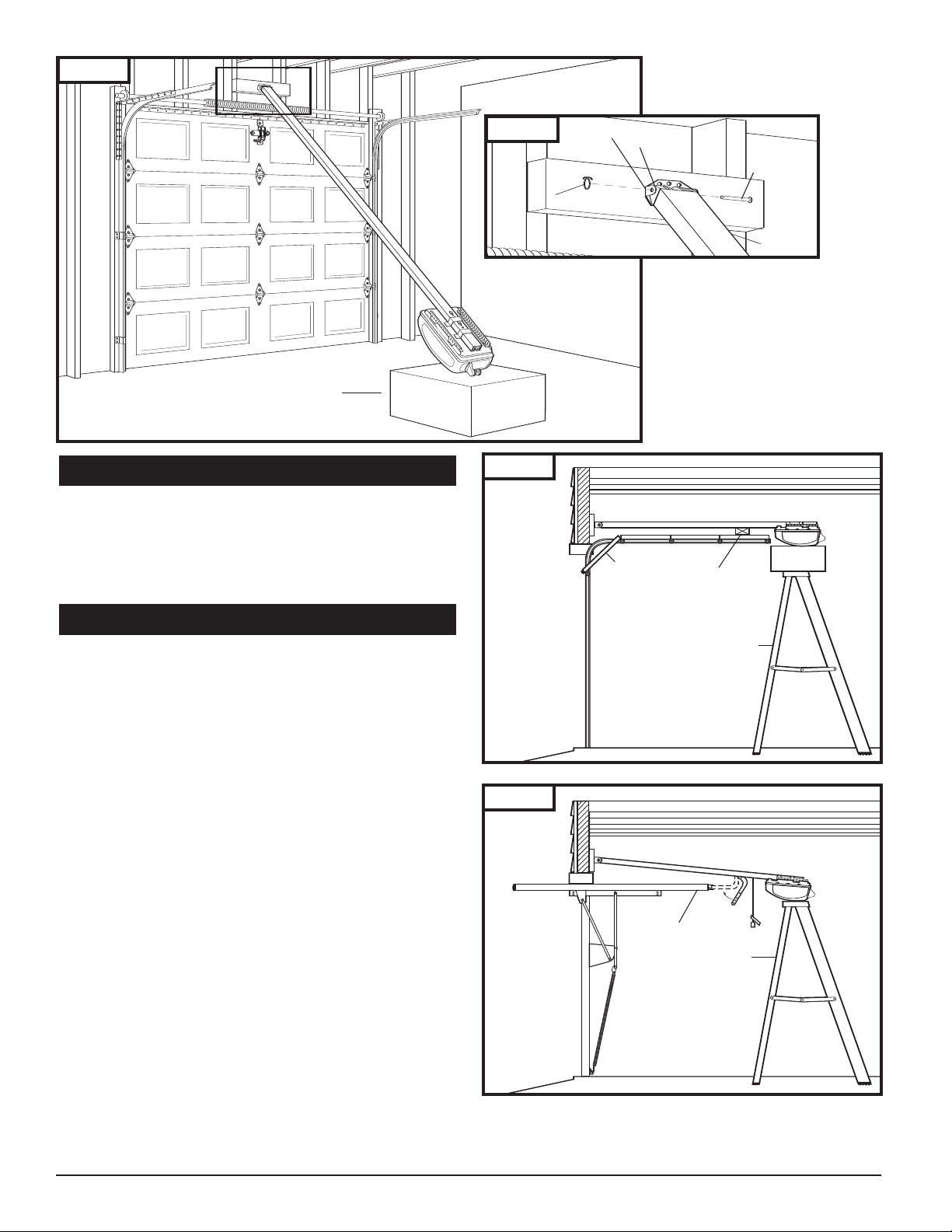
Stepladder
2x4 Laid Flat
Door
Stepladder
Door
Header Bracket
Rail End-Stop
C
otter Ring
1/4 x 3-1/4”
Clevis Pin
Rail
Fig. 17
Fig. 17A
Opener Box
7-5. ATTACH RAIL TO HEADER BRACKET
■ Support opener head slightly off the floor.
■ Lift the opposite end of the rail up to the header bracket.
■ Position rail end-stop within the openings in the header
bracket. Insert header clevis pin (1/4” dia.) through rail
end-stop and header bracket, then attach cotter ring to
end of pin. See Fig. 17A.
7-6. POSITION OPENER FOR MOUNTING
■ Once rail is attached to header bracket, support opener
powerhead on ladder, or use the assistance of another
person to support opener powerhead high enough so
door can open without hitting the rail.
A. SECTIONAL DOORS AND ONE-PIECE
DOORS WITH TRACK:
■ Open garage door to fully opened position, and place a
50mm board between the door and the rail. See Fig. 18.
■ The 2x4 pr
rect mounting height of the opener.
cor
ONE-PIECE DOORS WITHOUT TRACK:
B.
■ Disconnect tr
knob. Move tr
■ Open door all the way so that it is parallel to the floor
or slightly tilted towar
SHOULD NOT BE TILTED TOWARD THE BACK OF GARAGE.
■ Position opener so that top of opener head is level with
top of opened door.
■ To check for correct mounting height, temporarily position
curved door arm as if connecting to door bracket. See
Fig. 19. The long side of the arm should be parallel to the
floor when door is fully opened. Raise or lower
powerhead so that arm will be parallel to floor.
■ Temporarily support head at this height, and prepare to
mount the opener to ceiling.
ovides an easy method of ensuring the
olley by pulling down on emergency release
olley toward opener head.
d the front of the garage. DOOR
,
Fig. 18
50mm board
Fig. 19
10
Page 11
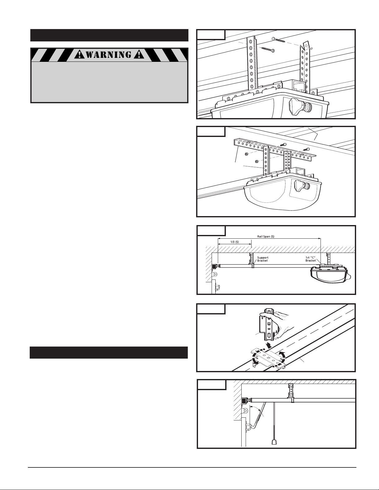
7-7. MOUNT OPENER TO CEILING
Joists (may be
hidden behind
drywall)
Perforated
Angle
Rail
Support
Bracket
Angle
Fig. 20
If not pr
operly secured, the opener
could fall and injure someone.
e opener to structural supports or
Secur
framing. Do not mount to drywall, plaster,
or other such material.
■ Position opener head so that rail is lined up with center
line of open door.
■ Line up hanger brackets (not provided) with ceiling joists
or framing to locate wher
e brackets are to be fastened.
See Fig. 20.
■ Mark location for 5/16" lag screws (not provided), and
drill two 3/16" pilot holes.
■ Fasten hanger brackets to joists using lag screws.
■ If garage framing supports are not visible, attach a length
of perforated angle or a 50mm board to the ceiling, securing it to the hidden joists with lag screws long enough to
fasten firmly to garage framing (extra hardware items not
provided). Then, attach one end of hanger brackets to the
perforated angle or 50mm board mounted to ceiling.
Attach other end of hanger brackets to opener’s chassis
angle iron. See Fig. 21 for alternate mounting methods.
■ Once opener is securely fastened in position, remove
wood blocks and temporary supports and lower door.
Check door for proper operation and clearance by
manually moving door to full open and closed position.
If door hits rail at any point, raise opener head slightly
higher and re-mount in position.
Fig. 21
Fig. 22
NOTE: To provide additional support for rails 13’ length and
longer, use optional support bracket. (Accessories p.32)
■ Measure the rail’s overall span. Bracket is located on 1/3rd
of the overall rail span from the door header bracket end.
See Fig. 22
■ Place support bracket over rail (close side) on a diagonal.
Make sure support securement clamps clear rail sides.
■ Secure bracket onto rail by twisting support bracket as
indicated in Fig. 22A.
■ Attach mounting strap (not provided) to support bracket
and secure by fastening it to the ceiling.
7-8. CONNECT ARM TO DOOR AND TROLLEY
■ Make sure door is fully closed.
■ Remove tape from rail holding straight door arm
(sectional door only) and allow door arm to hang freely.
■ Pull the manual release cord on the trolley to disconnect
trolley from chain or belt connector. Slide trolley to
position it about 100mm (4") away from the door.
Fig. 22A
Fig. 23
11
Page 12
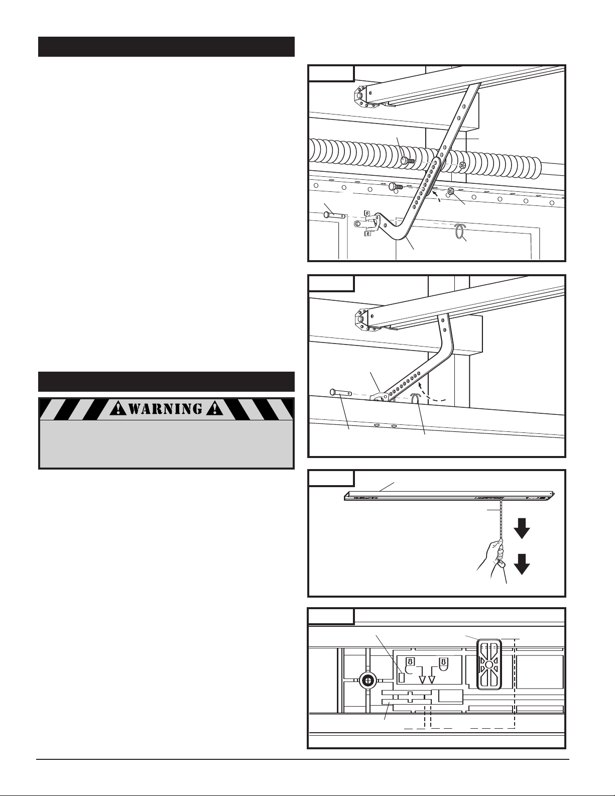
7-8. CONNECT ARM TO DOOR AND TROLLEY
Door Bracket
(for One-Piece Door)
Clevis Pin
Cotter Ring
5/16”-18 x 3/4”
H
ex Bolt
5/16” -18
Lock Nut
5/16” x 7/8”
Clevis Pin
Cotter Ring
C
urved Door Arm
Straight Door Arm
Rail
Emergency Release Cord
PULL DOWN
Red Emergency Release Knob
The release cord and knob should be adjusted
to hang 6 ft. above garage floor. To adjust:
■
Slide knob and tag up on cord.
■
Tie new knot at correct height.
■
Cut excess cord, leaving approximately 1”
after knot.
■
Heatseal end of cord with match or lighter
to prevent fraying.
■
Slide knob and tag back into place.
■
Check operation of emergency release.
Unlock
Latch
Lock
Red Catch
Indicator Window
A. SECTIONAL DOORS:
■ Position curved door arm into door bracket channel so
that shor
t end of arm will be attached to door bracket.
See Fig. 24. Curved door arm should be attached roughly
at the same height as the top rollers of the door.
■ Align cur
ved door arm and bracket holes, then insert clevis
pin through holes. Attach cotter ring to hold pin in place.
■ Position straight arm and curved arm to form an angle
with the door (Fig. 23 p.11) and at least two sets of holes
line up. Select two overlapping holes as far apart as possible and secur
e arms together with hex bolts (5/16-18) and
lock nuts.
B. ALL ONE-PIECE DOORS:
■ Curved door arm should already be attached to trolley in
place of straight door arm. See Fig. 16, p. 9.
■ Position free end of curved arm into door bracket slot.
Align curved door arm and bracket holes, then insert clevis
pin (5/16” dia.) through holes. Attach cotter ring to pin to
hold in place. See Fig. 25.
C. SECTIONAL AND ONE-PIECE DOORS:
■ After connecting appropriate door arm, ensure trolley is
disengaged. Check for proper door operation by manually
lifting then lowering to fully opened and closed positions.
■ Readjust door arm if needed.
PULL DOWN ON RELEASE KNOB TO LOCK TROLLEY,
THEN MOVE DOOR MANUALLY UNTIL TROLLEY LOCKS
WITH CHAIN OR BELT CONNECTOR.
Fig. 24
Fig. 25
7-9. CHECK EMERGENCY RELEASE
Use extreme care when pulling release knob.
DO NOT use knob to pull door open or closed.
The emergency release cord with red knob, which are
already attached to the trolley, are extremely important parts
of the opener system Fig. 26. Pulling the release cord disengages the door from the opener. This allows the door to be
moved manually up and down independent of the opener
motor.
If the door is in the open position, use extreme care
when using the release.
Use emergency release to disconnect the door if the power
is out. It should also be used if for some unforeseen reason
the door strikes a person or object during its travel and does
not automatically reverse off the obstruction.
To release door—pull firmly down on red knob. (Fig. 26)
Prior to re-engaging door, ensure that all obstructions are
removed and door is operating properly manually. Before
re-engaging trolley with a chain or belt connector, pull
down knob again, then release. The red catch will stop in
the “lock” position (see Fig. 26A). Now the door can be
reconnected by moving it manually and bringing it into
position when the connector is inside of the trolley.
12
Except for emergency situations,
use knob only when door is closed.
Fig. 26
Fig. 26A
Page 13
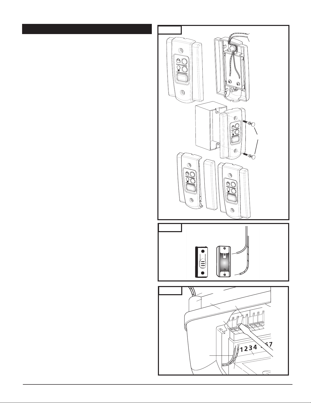
7-10. INST
To Terminal
#3 Screw
T
o Terminal
#4 Screw
4
3
Wire Guide
Chassis
Terminal Holes
Tab
Terminal Numbers
Wiring from Wall Control
To Terminal 3
To Terminal 4
Front
Doorbell-Type
Pushbutton
ALL WALL CONTROL PANEL
The control panel must be mounted inside the garage
within sight of the garage door, clear of all moving garage
door par
ts or any associated parts—and at least 1.3m (5Ft)
above the floor to prevent the use of these controls by chil-
en. The device should only be used when the door is in
dr
clear sight of the user and the door area is free of people or
any obstructions.
■ Attach 2-conductor wire to the screw terminal on back of
ol panel. See Fig. 27 (Back). White wire attaches to
contr
terminal #3 screw, white wire with color stripes attaches
minal #4 screw.
to ter
■ Position wall control panel onto wall in desired location.
■ Mark hole location on wall.
■ Drill 1/16” pilot holes into wall.
■ Insert and tighten screws to secure control panel to wall.
■ Make sure wiring is routed out from behind control
through one of the cutouts to avoid pinching the wires.
If mounting to drywall instead of wood, drill 3/16” pilot holes
and use anchors provided.
If mounting to electrical box that is prewired for this purpose,
mount directly to box with proper screws provided .
■ Run wires from wall control panel along wall and ceiling
to opener powerhead. Use the staples that are provided
to secure wiring to wall, joists and ceiling. Do not pinch
wiring. Drive staples with only enough force to hold
wiring in place.
■ Insert white single wire from wall control into terminal #3
and single color striped wire into terminal #4. (Fig. 29)
Fig. 27
Screw caps
NOTE: If wires are difficult to insert, a screwdriver may be
used to depress the terminal “tab” while inserting the
wires. To remove wires, depress tab again and pull wires
out.
Multiple wall controls may be installed in parallel with
wires connected to terminals #3 and #4.
■ Detach right side panel from one of the wall controls.
(Fig. 27)
■ Attach wiring to back of both wall controls (White wires to
terminal #3 screws, wires with stripes to terminal #4 screws.)
■ Follow the same steps as above to mount additional wall
control panels and wire connections.
Doorbell-Type Pushbutton
Follow the same steps as above with one exception, mark
both mounting holes at same time, then drill and secure
unit to wall (in the case of the doorbell-type Pushbutton,
it does not matter which wire attaches to which terminal.
See Fig. 28.
Fig. 28
Fig. 29
13
Page 14
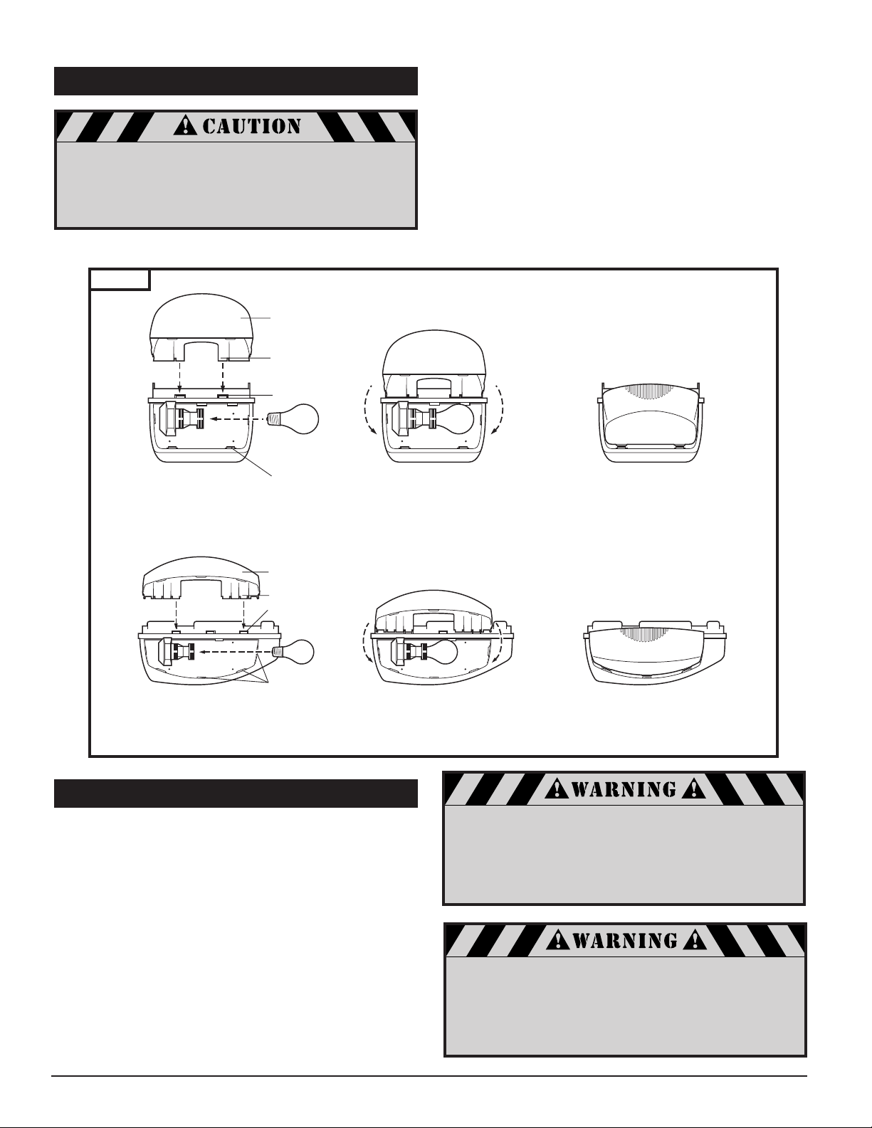
Hinge lamp lens downward
line up tabs with slots in
housing, and snap into place.
Snap lamp lens tabs
into slots in chassis
Install Bulb
Lamp Lens
Lamp Lens T
abs
Chassis Slots
Housing Slots
Lamp Lens
Lamp Lens
Tabs
Chassis Slots
Housing Slots
Install Bulbs
Snap lamp lens tabs
into slots in chassis
Hinge lamp lens downward,
line up tabs with slots in
housing, and snap into place.
7-11. INST
ALL LIGHT BULBS AND LENSES
DO NOT use a bulb with a rating higher than
60W (Watts) for 120V (Volt) application and 40W for
230V, or larger than a Standard size bulb.
onger or larger bulb may result in
A str
fire or damage to the opener.
Fig. 30
■ Install bulb (not provided) into lamp socket(s).
■ Install lamp lens(es). Two lenses for a EX-2007 model, one
lens for a EX-2005 model.
■ Line up lamp lens tabs with slots in housing and snap
ely into place. Repeat same procedure with second
secur
lamp lens on the opposite side, if you have an EX-2007
power head.
■ Line up lamp lens tabs with corresponding slots in chassis.
Snap lens onto chassis for EX-2005 model.
■ To remove lamp lens, pull lamp lens to unsnap from
housing and chassis.
EX-2005
7-12. CONNECT TO POWER
For 120V application, to reduce the risk of electric shock,
your opener is provided with an insulated power cord with a
3-prong grounding plug. The cord must be connected to a
standard grounding outlet. If there is no outlet available at
the location, you must have a qualified electrician install an
approved grounded outlet in this area.
■ Plug the opener into a properly grounded outlet.
■ An indicator light (LED #8) on the opener control panel
will turn on showing that the power is “On” and the
opener is ready to set the adjustments.
■ DO NOT operate or run the opener at this time.
EX-2007
To prevent electrocution or fire, installation
and wiring must be done in accordance with
local electrical and building codes. DO NOT use
an extension cord. DO NOT use a 3 to 2 plug
adapter. DO NOT modify or cut off the
To prevent electrocution, disconnect the opener
from power and turn off power at circuit
breaker for the circuit you will be using
grounding pin on the plug.
to connect to the opener.
14
Page 15
8. OPENER PROGRAMMING
Strengthen where needed.
Install light bulb.
Typ e E14, max. 40 Watt (not included).
O
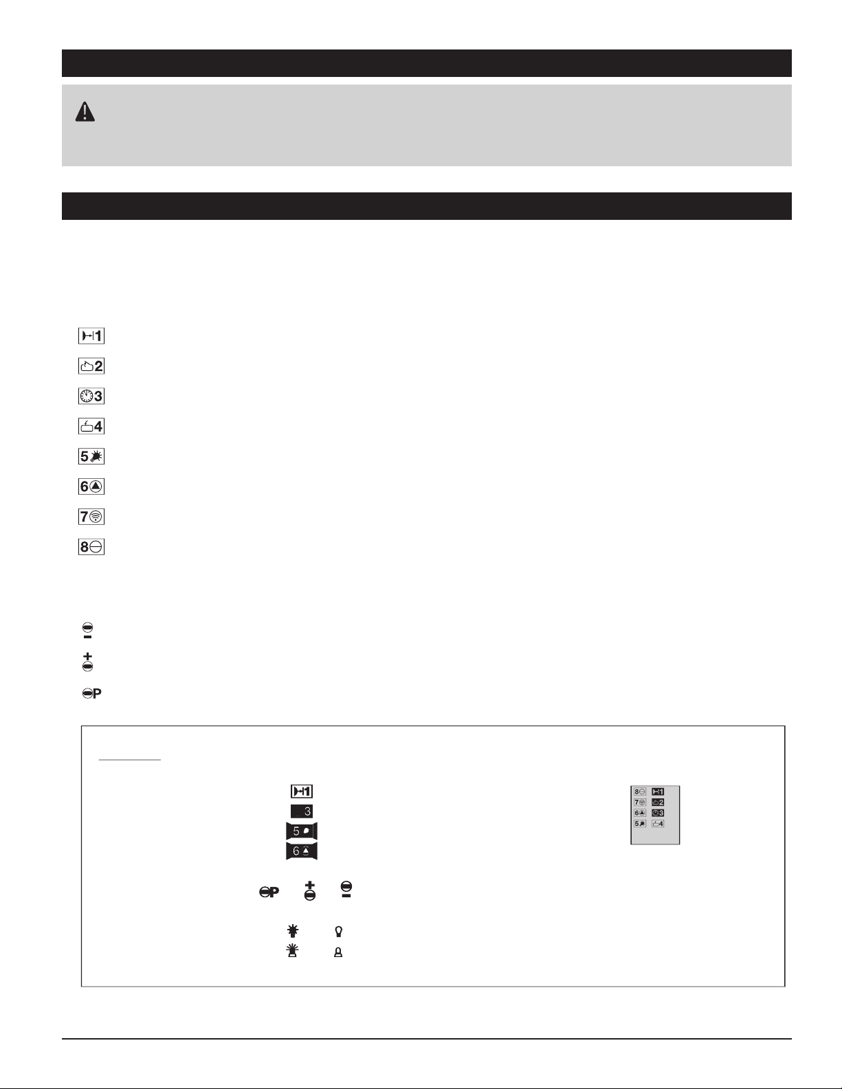
PERATOR CONTROL PANEL INDICATIONS
Your automatic door opener is provided with an easy to read
LED display panel with
three program buttons.
Light icons:
external beam break
Door in set position OPEN
automatic timer
Door in set position CLOSED
Door passes reference point
Malfunction. CHECK error message by pressing "P" button briefly.
operator impulse (slow flash when on vacation lock)
power on (230V)
Attention: before you start Opener programming please make sure your
carriage is engaged to chain or belt and door arm is attached to door.
Install light bulb.
Typ e E14, max. 40 Watt (not included).
O
PERATOR CONTROL PANEL INDICATIONS
Your automatic door opener is provided with an easy to read
LED display panel with
three program buttons.
Light icons:
external beam break
Door in set position OPEN
automatic timer
Door in set position CLOSED
Door passes reference point
Malfunction. CHECK error message by pressing "P" button briefly.
operator impulse (slow flash when on vacation lock)
power on (230V)
Adjustment buttons
Program button "decrease"and
CLOSE
test button
Program button "increase"and
OPEN
test button
Programming button
L
EGEND
LED off i.e.
LED illuminated i.e.
LED blinking i.e.
LED rapid blinking i.e.
Button pressed or or
Operator light bulb on: off:
External Lightson: off:
Default setting: i.e.
3/8
Attention: before you start Opener programming please make sure your
carriage is engaged to chain or belt and door arm is attached to door.
Strengthen where needed.
Install light bulb.
Typ e E14, max. 40 Watt (not included).
Attention: before you start Opener programming please make sure your
carriage is engaged to chain or belt and door arm is attached to door.
8-1. OPENER CONTROL PANEL INDICATIONS
Your automatic door opener is provided with an easy to read 8 LED display panel with three
programming buttons.
Light icons:
Adjustment Buttons:
15
Page 16
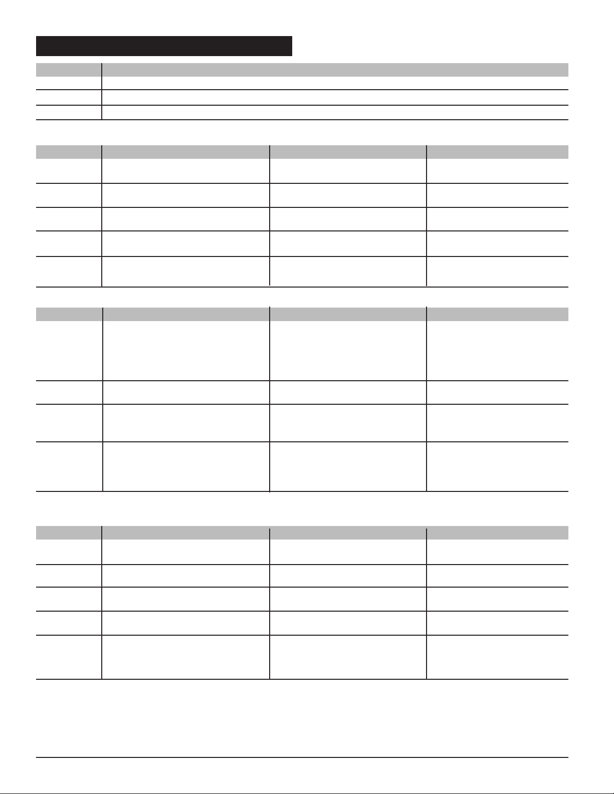
8-2. PROGRAMMING OVERVIEW
Menu Basic Settings
Menu 1 Programming 'door open position'
Menu 2 Programming 'door closed position'
Menu 3 Programming of remote control
LEVEL 2 Advanced Settings Explanation Factory Settings
Menu 1 Add beam break (photo eye system) Setting whether the opener without photo eye system
runs with or without photo eye
Menu 2 Set maximum OPENING force The sensitivity of power limit step 6/16
can be set in steps from 1 - 16
Menu 3 Set maximum CLOSING force The sensitivity of power limit step 6/16
can be set in steps from 1 - 16
Menu 4 Set 'offset' learned power limit The sensitivity of power limit step 7/15
(sensitivity) can be set in steps from 1 - 15
Menu 5 Set 'operator speed' The speed the door is moved by step 16 (max. speed)
the operator can be set
LEVEL 3 Advanced Settings Explanation Factory Settings
Menu 1 Set door open period The time the door remains open deactivated
until it closes automatically.
Note: This function only works
when photo eye is connected
and programmed.
Menu 2 Set warning phase time Setting whether a signal light deactivated
will flash before the door closes
Menu 3 Set start-up warning phase Setting whether a signal light warning before start
will flash before the door starts deactivated
to move with a delayed door start
Menu 4 Set early closing after passing Setting whether the door will no
the driveway photocell close after passing the photo eye
and before the set time has
expired
LEVEL 4 Advanced Settings Explanation Factory Settings
Menu 1 Set period light remains on The light time of the operator 180 sec.
can be programmed
Menu 2 Set timed security cut-out Programs the maximum 80 sec.
door travel time
Menu 3 Set external signal light The signal light can be set to flash none
or permanent light
Menu 4 Set operator lighting The operator light can flash at none
automatic time function
Menu 5 Set external relay alarm function The electric push open security none
device can be programmed as
alarm output signal
16
Page 17
8-3. PREPARATION FOR PROGRAMMING
REPARA FOR PROGRAMMING
• The opener has to be mounted ready for operation
• The door is not yet closed completely
• If there is a beam break
(photo eye safety system),
it
should be connected!
Advice:
If the photo eye is correctly mounted and aligned, the function 'photo eye' is recognized
automatically during programming!
Advice:
The programming is cancelled if none of the three buttons ( , , ) is actuated during
a time period of more than 120 sec.
All functions saved before with button remain unchanged.
When programming is cancelled, LED is flashing.
After shortly pressing button the error message7 is displayed.
Advice:
To determine the error number add the figures of the irregularly flashing LED ’s.
See as well 'err or messages'.
In case of a malfunction the control light MALFUNCTION is flashing.
Attention:
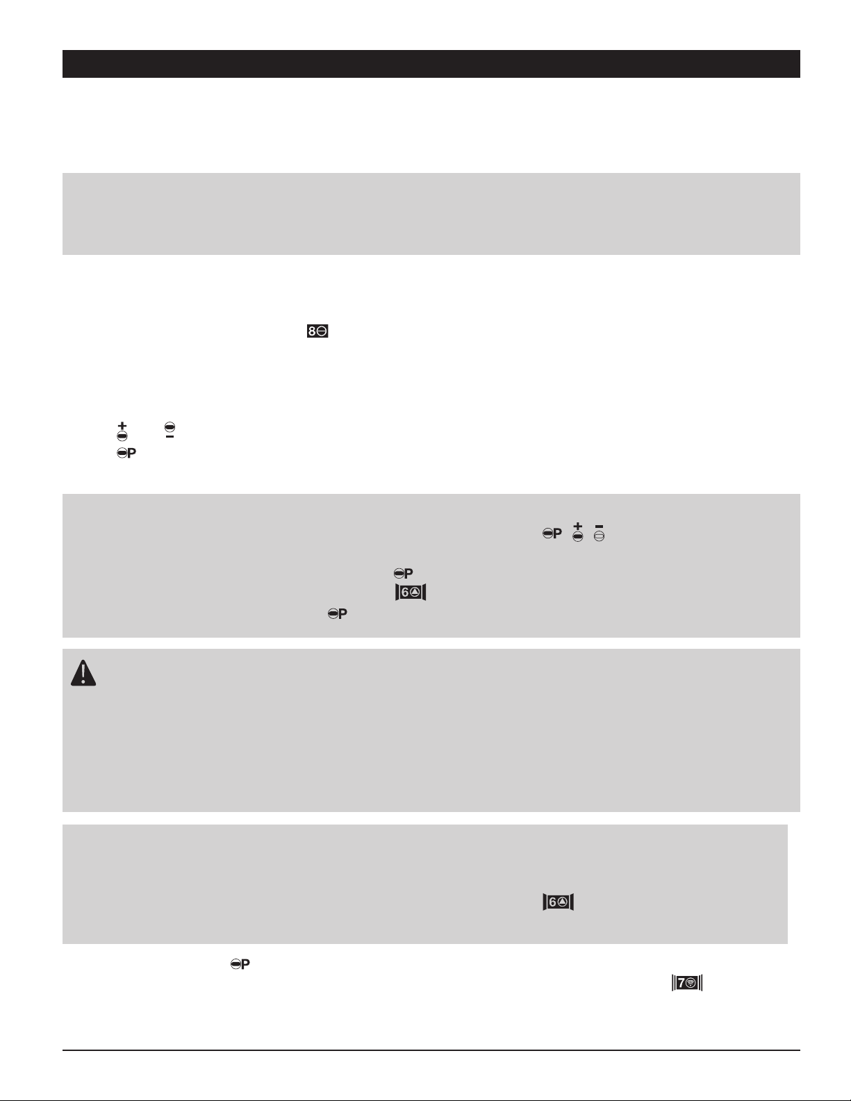
The opener has four programming levels.
For normal operation of the opener you only program the end positions and
the remote control in the Basic settings.
Changes in the extended programming level may only be carried out
by specialists.
• When the door opener is turned on (plug in power cord) it runs a self-test;
all 8 LEDs will glow and opener light will illuminate for approximately 2 seconds.
When the light is off and LED is illuminated the opener is in normal operating mode.
A
DJUSTMENTBUT TONS
:
All settings and adjustments can be made with the three adjustment buttons.
Use and to change settings of chosen program menu
to store menu setting and go to next menu.
• Shortly press button .
-> The current error number is displayed by irregularly flashing LED's (e.g. error ).
(4)
17
Page 18
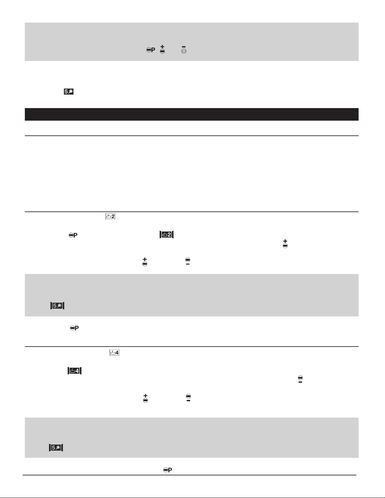
Set door OPEN position
Set door CLOSED position
Program hand transmitter
S
ET DOOR OPENPOSITION
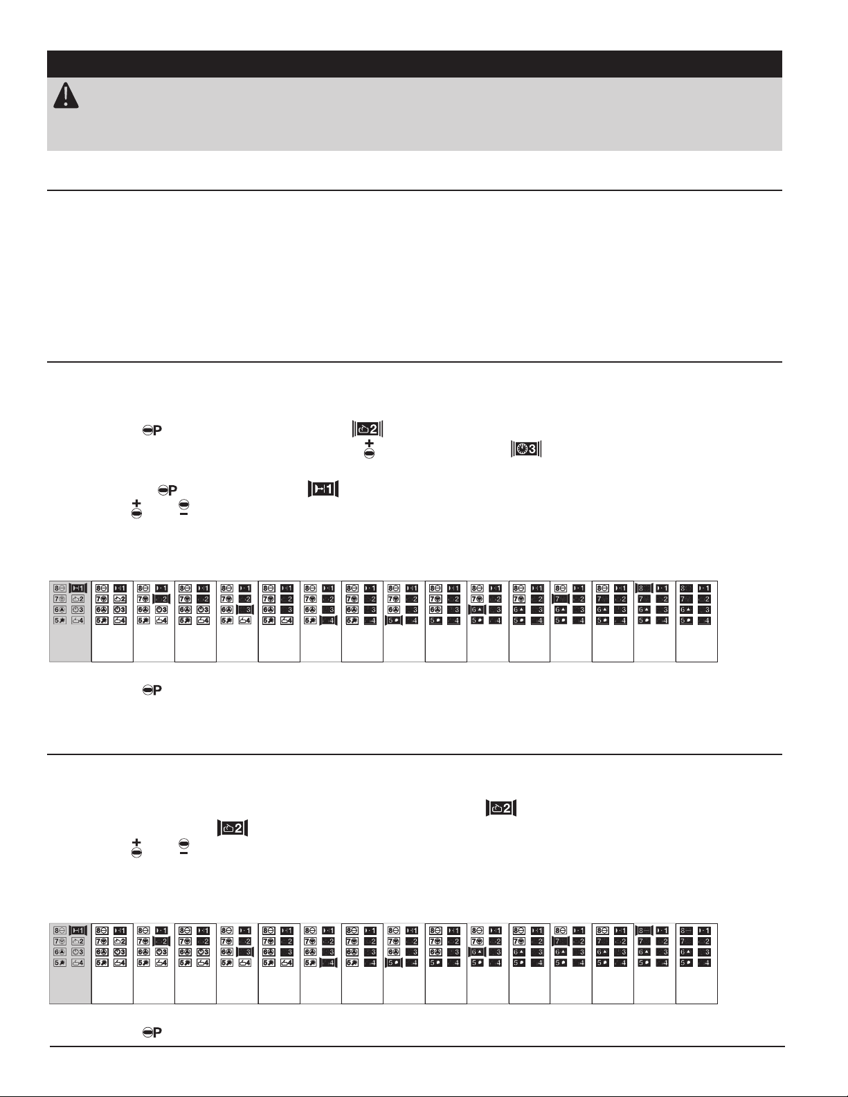
1. Press for 2 seconds until LED blinks and all others are illuminated.
2. To move the garage door to desired fully
OPEN
position press & hold the until desired
DOOR OPEN
position is reached.
For fine adjustment use the (
OPEN
) and (
CLOSE
) buttons.
Advice:
The reference point has to be passed 1x.
will light up briefly when reference point has to be passed 1x.
Advice:
The reference point has to be passed 1x.
will light up briefly when reference point has to be passed 1x.
3.Press to store and to go to Menu 2 .
S
ET DOOR CLOSE POSITION
1. LED blinks and all others are illuminated.
2. To move the garage door to desired fully CLOSED position press & hold the until desired
DOOR CLOSE
position is reached.
3. Once door position is correct press to store and go to Menu 3.
Menu Overview:
1.
2.
3.
To Set Up the Opener:
Menu 1
Menu 2
For fine adjustment use the (
OPEN
) and (
CLOSE
) buttons.
8-4. BASIC SETTINGS
Advice:
All menus can be reset by a RESET function to the original values set by factory.
Reset is activated by pressing , and together for more than 30 seconds.
op p point
• LED shortly glows up.
Display of the reference point
The opener passes the reference point sensor:
• LED shortly glows up.
18
Page 19
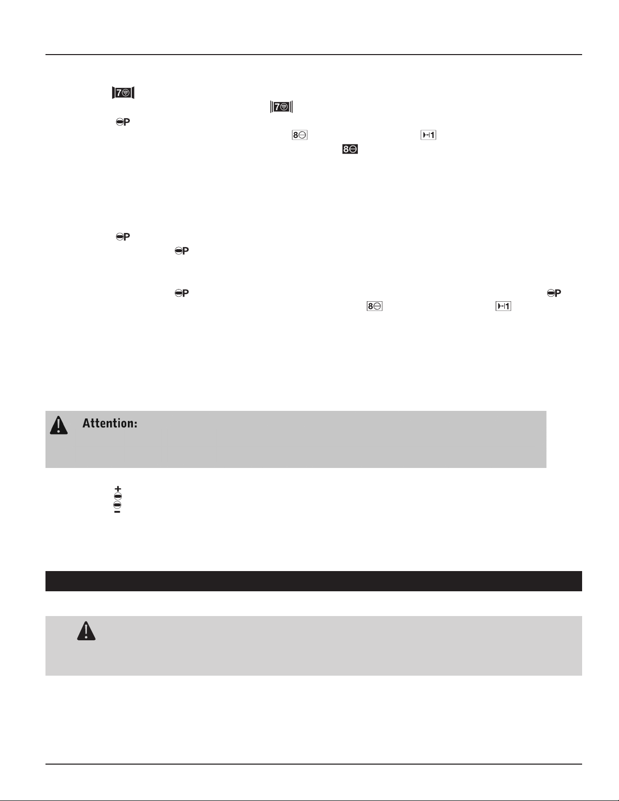
Run the opener (with door engaged) without interruption two complete cycles from position
1. LED blinks and all others are illuminated.
2. Press transmitter button until LED blinks rapidly
3. Press to store multi-bit transmitter code and to finish basic programming. LEDs will
automatically turn off starting at LED and ending at LED .
The opener is now in operational (normal) mode.
To change the settings of an individual menu:
1. Press for approximately 2 seconds until LED blinks
2. Repeatedly press until desired indicator blinks.
If an individual programming menu is skipped its settings remain unchanged.
3. Follow individual instructions for Program menu
4. Repeatedly press to scroll through the menus. When you reach last menu by pressing
the LEDs will automatically turn off starting at LED and ending at LED .
Menu 3
Program the Transmitter Code
Making Adjustments
DVANCED SETTINGS
Attention:
Programming the advanced features of this operator must only be undertakenby fully
trained and qualified personnel. Please contact your dealer for details.
A
DVANCEDPROGRAMMINGFEA TURES
:
•Advanced settings ( )
• Automatic closing ()
•(External) Lighting ( )
Level 2
Level 3
Level 4
‘DOOR CLOSED’ to position ‘DOOR OPENED’ and vice versa.
During these two learning travels the opener determines the maximum push and pull force which
is required to move the door. After two complete cycles the opener is ready for operation.
These settings remain unchanged even if power supply is interrrupted but they can, if necessary,
be changed as described in “Advanced Settings”.
If the opener cuts out during the test run and LED 8 and LED 2 are flashing quickly
(error number 10 /automatic cut out) set the automatic cut out. See section 8-5
“Advanced Settings” Level 2 Menu 2 and 3.
Test the Opener:
Press button . The door must travel to the ‘door open’ position.
Press button . The door must travel to the ‘door closed’ position.
Shortly press the button on your hand transmitter. The opener moves the door into ‘OPEN’ direction.
Press the button on your hand transmitter again during the opener run. The door must stop.
Press button again. Door begins to move in the opposite direction.
8-5. ADVANCED SETTINGS
19
Page 20
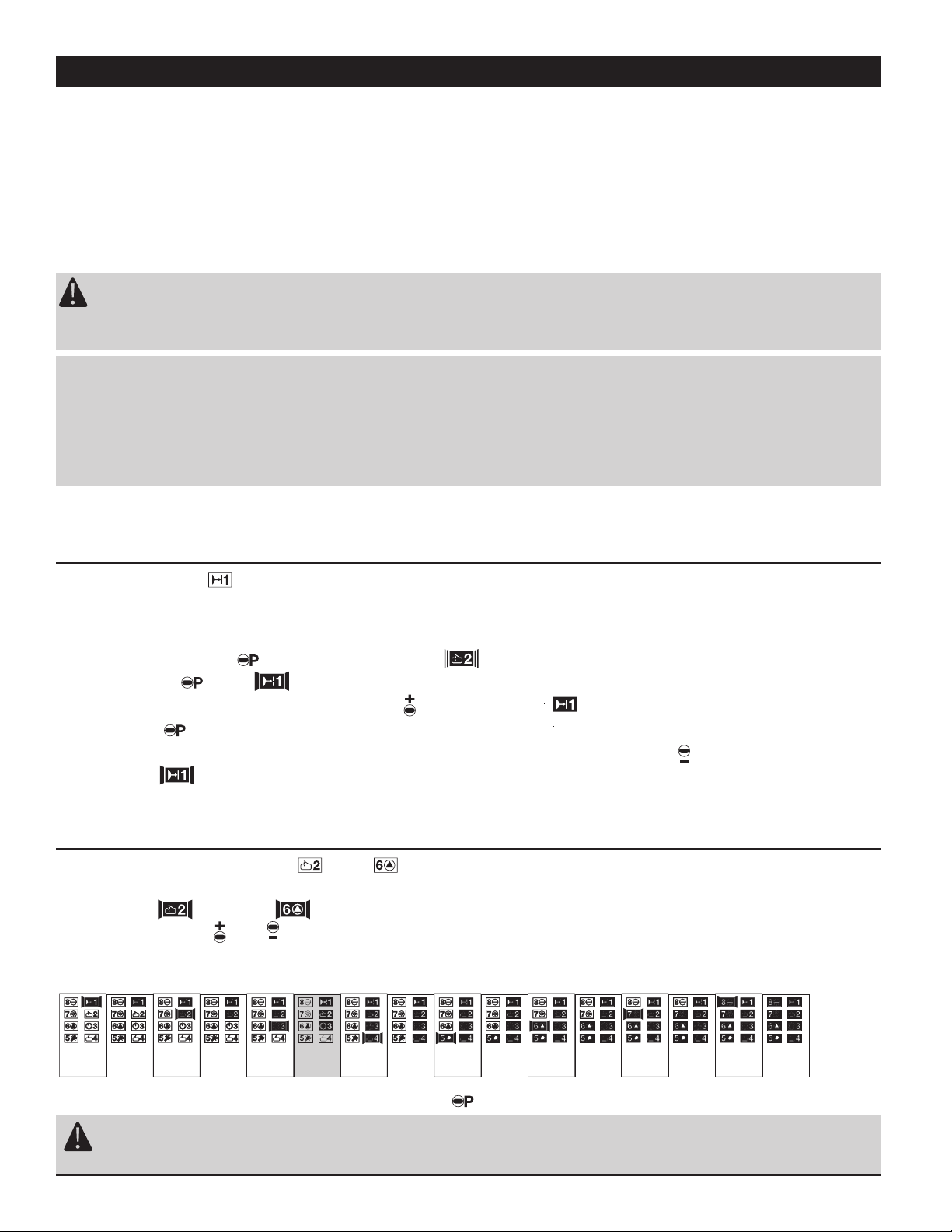
Add beam break (photo eye safety system)
Set maximum OPENING force
Set maximum CLOSING force
Set offset learned power limit (sensitivity)
Set "opener speed"
ANCED
SETTINGS
Menu Overview Level 2
1.
2.
3.
4.
5.
LEVEL 2 ADVANCED SETTINGS
Add beam break (photo eye safety system)
Set maximum OPENING force
Set maximum CLOSING force
Set offset learned power limit (sensitivity)
Set "opener speed"
Advice:
Changes in the programming levels of extended opener functions should be carried out by
specialist personnel.
Attention:
The automatic cut-out is set automatically. Only change it if necessary!
Set the automatic cut-out as sensitive as possible, according to EN 12445 and EN 12453.
1.
2.
3.
4.
5.
A
DD BEAM BREAK
*
*Photo eye safety system is an optional accessory.
Opener is in normal operating mode with not activated Beam break feature.
1. Press 10 seconds until LED flashes rapidly and all others are illuminated.
2. Release LED blinks and all others are illuminated.
3. To activate Photo eye feature press twice until LED illuminated.
4. Press to store settings and to go to Menu 2 .
S
ET MAXIMUMOPENING FORCEAND
1. LED and LED blink and all others are illuminated.
2. By pressing or set the desired maximum lifting force.
Each illuminated LED represents 1/16 of the maximum total force.
3. Once maximum opening force is set press to store and go to Menu 3.
16/1615/1614/1613/1612/1611/1610/169/168/167/166/165/164/163/162/161/16
Attention:
Set opening force as sensitive as possible (max. 150 N at closing edge)
Level 2 Menu 1
To Set Up Advanced Settings
Level 2 Menu 2
and hold
.
Note: To deactivate Photo eye follow the same procedure except press until
LED blinks rapidly.
Add beam break (photo eye safety system)
Set maximum OPENING force
Set maximum CLOSING force
Set offset learned power limit (sensitivity)
Set "opener speed"
Advice:
Changes in the programming levels of extended opener functions should be carried out by
specialist personnel.
Attention:
The automatic cut-out is set automatically. Only change it if necessary!
Set the automatic cut-out as sensitive as possible, according to EN 12445 and EN 12453.
Advice:
The setting of the automatic cut-out corresponds to the maximum power of the operator.
At the first travel to OPEN or CLOSE direction after 'POWER ON' the automatic cut-out
is effective according to the adjustment. F or further travels the self-learned power, that is
more sensitive, is effective. The automatic cut-out is still the upper limit of power.
20
Page 21
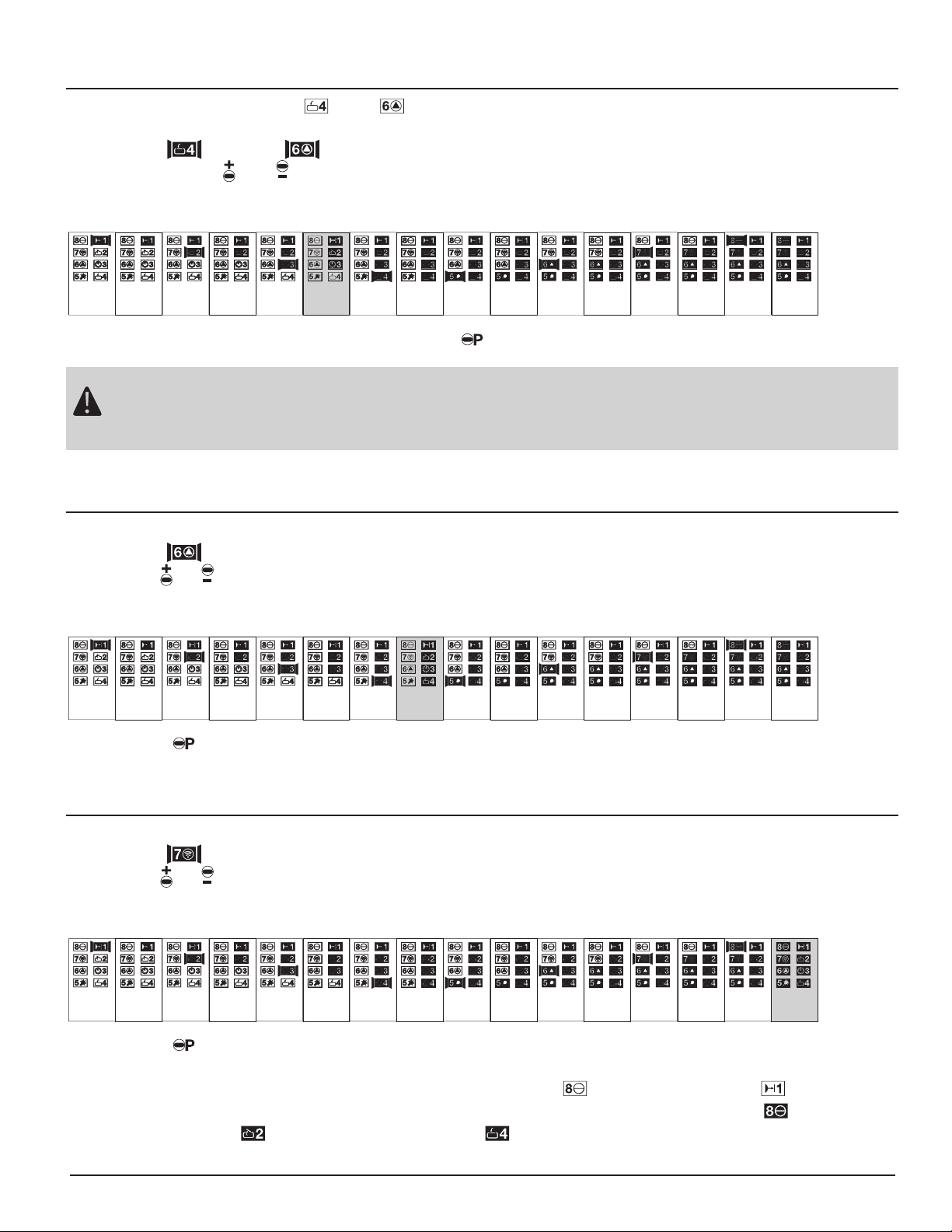
A
Set opening force as sensitive as possible (max. 150 N at closing edge)
Attention:
Set closing force as sensitive as possible (max. 150 N at closing edge)
S
ET MAXIMUM CLOSING FORCEAND
1. LED and LED blink and all others are illuminated.
2. By pressing or set the desired maximum closing force.
Each illuminated LED represents 1/16 of the maximum total force.
3. Once maximum closing force is set press to store and go to Menu 4 .
16/1615/1614/1613/1612/1611/1610/169/168/167/166/165/164/163/162/161/16
Level 2 Menu 3
SET OFFSET AUTOMATIC LEARNED POWER LIMIT
1. LED blinks and all others are illuminated.
2. Use or to change offset in increments of 1/16 of the maximum.
minimum offset: 1/15
maximum offset: 15/15
3. Press to store and go to Menu 5.
S
ET "OPENER SPEED"
1. LED blinks and all others are illuminated.
2. Use or to change the opener speed in steps of 7/16 to 16/16 (factory settings).
minimum speed: 7/16
maximum speed: 16/16
3. Press to store and to finish setting up the opener speed.
The LEDs will automatically turn off starting at LED and ending at LED .
Opener is now in operational (normal) mode (recognizable by illuminated LED ) and
possible LED (door fully open) or LED (door fully closed).
16/1615/1614/1613/1612/1611/1610/169/168/167/16
not
possible
not
possible
not
possible
not
possible
not
possible
not
possible
15/1514/1513/1512/1511/1510/159/158/157/156/155/154/153/152/151/15
disactivated
Level 2 Menu 4
Level 2 Menu 5
21
Page 22
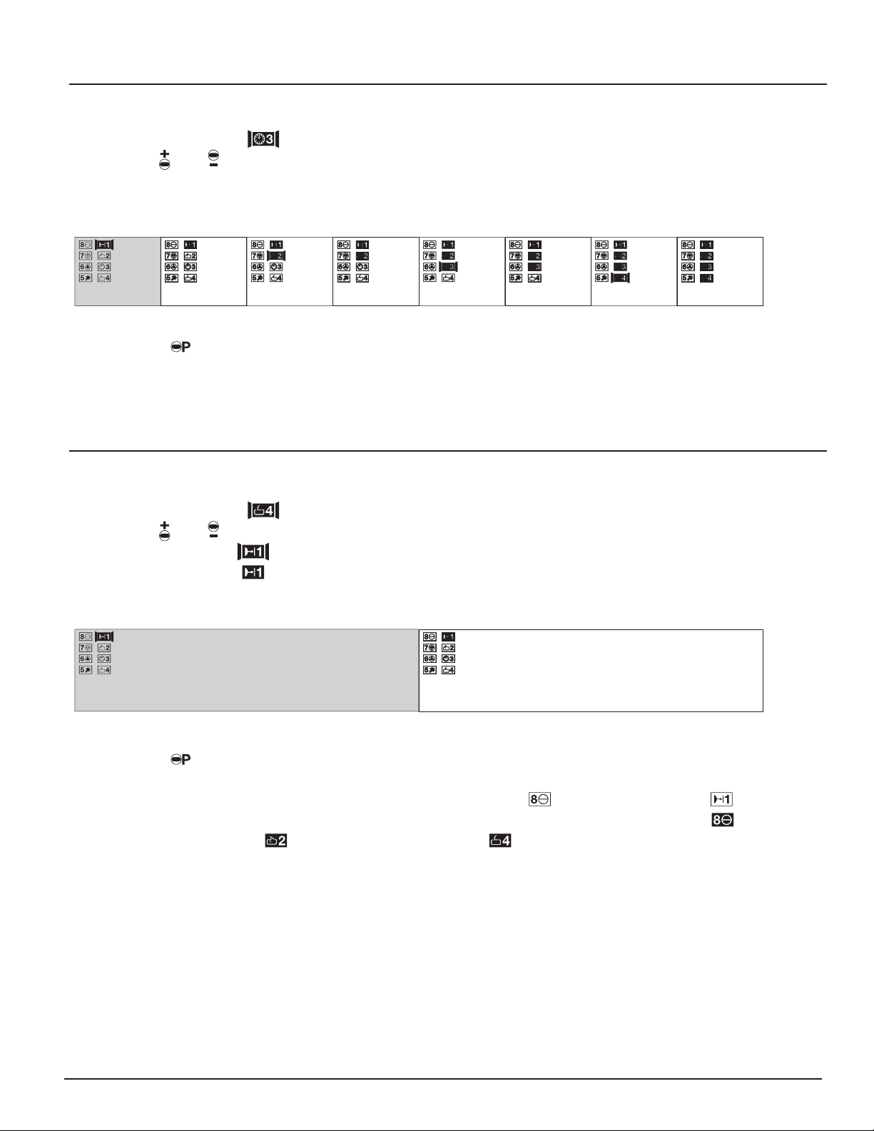
SETA
UTOMATICCLOSING
:
Attention:
When using this feature a photo eye safety system must be connected and programmed in
accordance with Level 2 Menu 1.
Set door open period
Set warning phase time
Set start-up warning
Set early closing after passing the driveway photocell
T
OSETUPAUTOMATICCLOSING
:
S
ET DOOR OPENPERIOD(AUTOMATIC TIMER
)
Opener is in normal operating mode
1. Press for 10 seconds until LED flashes rapidly and all others are illuminated.
Still hold the P button and press the button until LED blinks and all others are
illuminated.
2. Release where after LED blinks.
3. Use and to change the door open period (time open).
minimum time:5 seconds
maximum time: 255 seconds
4. Press to store and go to Menu 2.
S
ET WARNING PHASE TIME
After having programmed the automatic timer function LED will blink.
1. Make sure LED is blinking and all others are illuminated
2. Use and to change the warning phase
minimum phase:2 seconds
maximum phase: 70 seconds
3. Press to store and go to Menu 3.
70
seconds
65
seconds
60
seconds
55
seconds
50
seconds
45
seconds
40
seconds
35
seconds
30
seconds
25
seconds
20
seconds
15
seconds
10
seconds
5
seconds
2
seconds
timer
dectivated
255
seconds
180
seconds
150
seconds
120
seconds
100
seconds
80
seconds
50
seconds
40
seconds
35
seconds
30
seconds
25
seconds
20
seconds
15
seconds
10
seconds
5
seconds
timer
dectivated
Menu Overview Level 3
1.
2.
3.
4.
Level 3 Menu 1
Level 3 Menu 2
LEVEL 3 SET AUTOMATIC CLOSING
22
Page 23
S
ET START-UP WARNING
1. Make sure LED is blinking and all others are illuminated.
2. Use or to change the start-up warning phase
minimum phase: 0 seconds
maximum phase: 7 seconds
3. Press to store and go to Menu 4.
S
ET EARLY CLOSING AFTER PASSINGTHE DRIVEW AY PHOTO EYE
1. Make sure LED is blinking and all others are illuminated.
2. Use or to choose the required setting:
A.LED blinking: Door will close after set door open period
B.LED illuminated: Door will close immediately after driving through the
Beam Break
3. Press to store and to finish setting up the automatic closing feature.
The LEDs will automatically turn off starting at LED and ending at LED .
Opener is now in operational (normal) mode (recognizable by illuminated LED )
and possible LED (door fully open) or LED (door fully closed).
Door will close immediately after driving through
the Optical Sensor
Door will close after set door open period
7 seconds6 seconds5 seconds4 seconds3 seconds2 seconds1 seconds0 seconds
Level 3 Menu 3
Level 3 Menu 4
23
Page 24
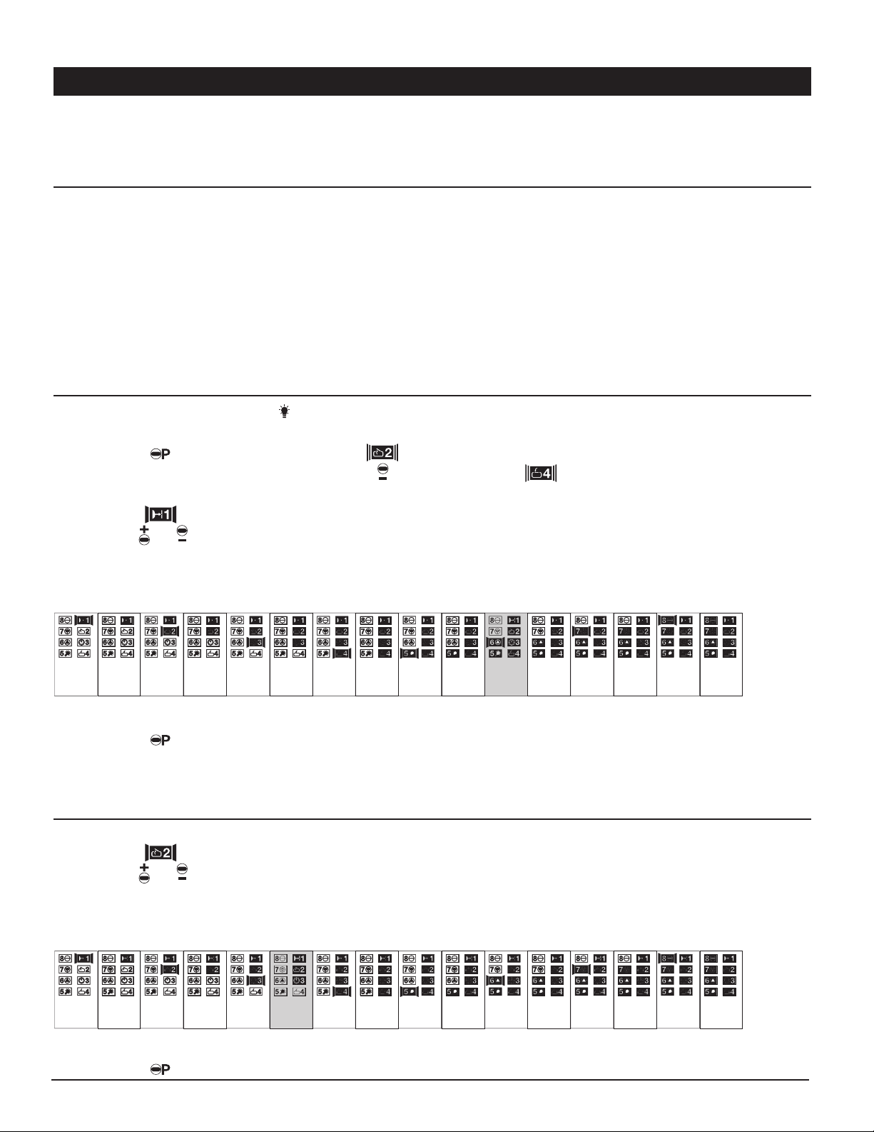
Your opener allows the connection of an external signal light provided the optional external light
relay kit is connected and the automatic closing function is activated.
Signal lights can be programmed to be: - constant illuminated signal light
- blinking signal light
M
ENUOVERVIEW LEVEL 4
Set period lights remain on
Set timed security cut-out
Set external signal lights
Set opener lighting
Set external relay alarm function
S
ET PERIOD LIGHT REMAINS ON
()
Opener is in normal operating mode
1. Press for 10 seconds until LED flashes rapidly and all others are illuminated.
Still hold the P button and press the button until LED blinks and all others are
illuminated.
1. LED blinks and all others are illuminated.
2. Use or to set desired period
minimum phase: 90 seconds
maximum phase: 240 seconds
3. Press to store and go to Menu 2.
S
ET TIMED SECURITY CUT-OUT(MAX TRAVEL TIME
)
1. LED blinks and all others are illuminated.
2. Use or to change value
minimum phase: 30 seconds
maximum phase: 240 seconds
3. Press to store and go to Menu 3.
240
seconds
220
seconds
210
seconds
200
seconds
190
seconds
180
seconds
160
seconds
140
seconds
120
seconds
100
seconds
80
seconds
65
seconds
55
seconds
50
seconds
40
seconds
30
seconds
240
seconds
220
seconds
210
seconds
200
seconds
190
seconds
180
seconds
170
seconds
160
seconds
150
seconds
140
seconds
130
seconds
120
seconds
110
seconds
100
seconds
95
seconds
90
seconds
C
ONTROLEXTERNALLIGHT
Level 4 Menu 1
1.
2.
3.
4.
5.
Level 4 Menu 2
LEVEL 4 CONTROL EXTERNAL LIGHT
24
Page 25
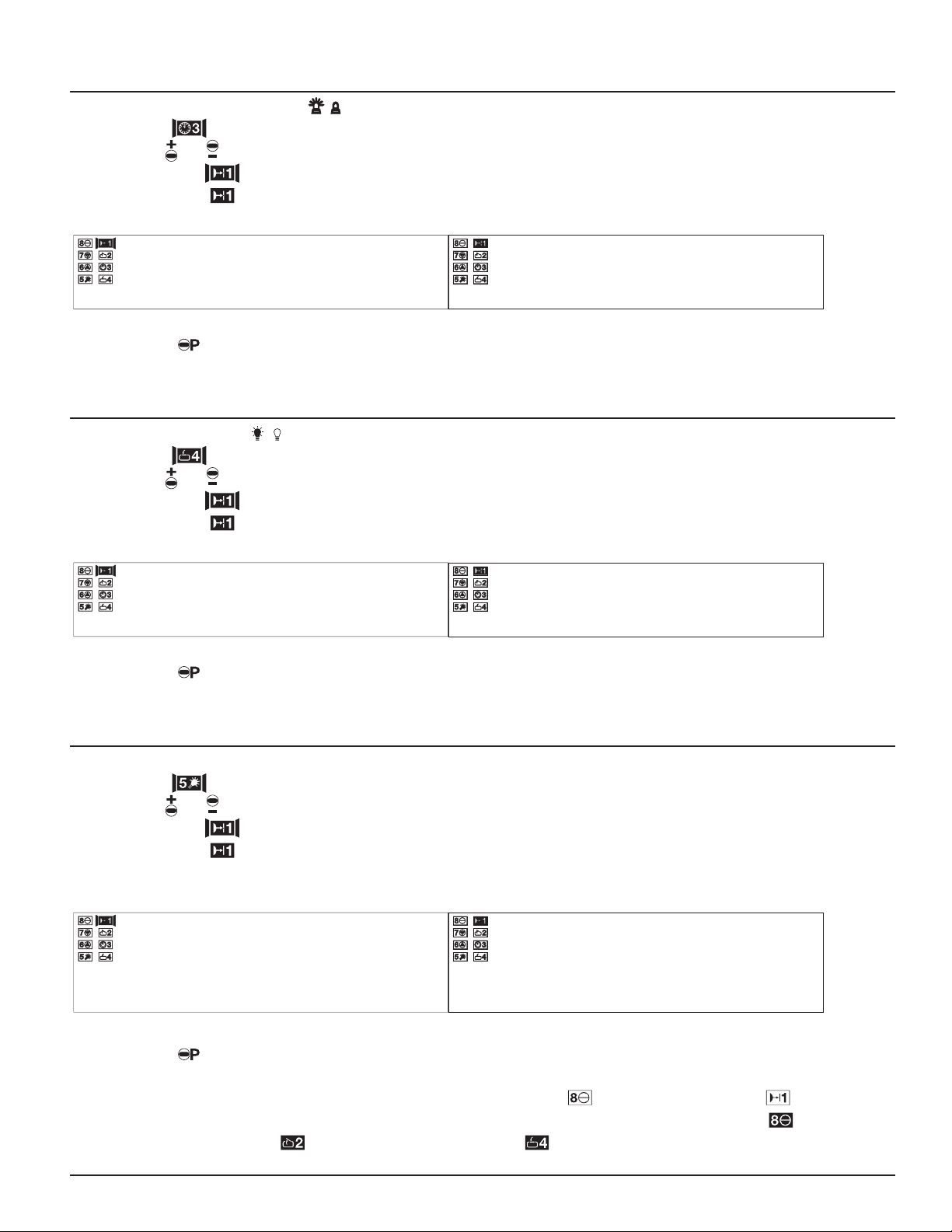
S
ET EXTERNAL SIGNAL LIGHTS
(/)
1. LED blinks and all others are illuminated.
2. Use or to set the signal light function
LED blinks:external signal will be illuminated
LED illuminated: external signal will blink
3. Press to store and go to Menu 4 .
S
ET OPENER LIGHTING
(/)
1. LED blinks and all others are illuminated.
2. Use or to set the signal light function.
LED blinks:opener light will be illuminated during warning phase
LED illuminated: opener light will blink during warning phase
3. Press to store and go to Menu 5 .
S
ET EXTERNAL RELAY ALARMFUNCTION
1. LED blinks and all others are illuminated.
2. Use or to set the light function
LED blinks:external light will be illuminated during lighting phase.
LED illuminated: external light relay 30 seconds alarm signal on actuation
of the back drive protection system
3. Press to store and to finish setting up the external light.
The LEDs will automatically turn off starting at LED and ending at LED .
Opener is now in operational (normal) mode (recognizable by illuminated LED )
and possible LED (door fully open) or LED (door fully closed).
External relay 30 seconds alarm signal on actuation of the
back drive protection system
External light will be illuminated during lighting phase
opener light will blink during warning phaseopener light will be illuminated during warning phase
ext
ernal signal will blinkexternal signal will be illuminated
Level 4 Menu 3
Level 4 Menu 4
Level 4 Menu 5
25
Page 26
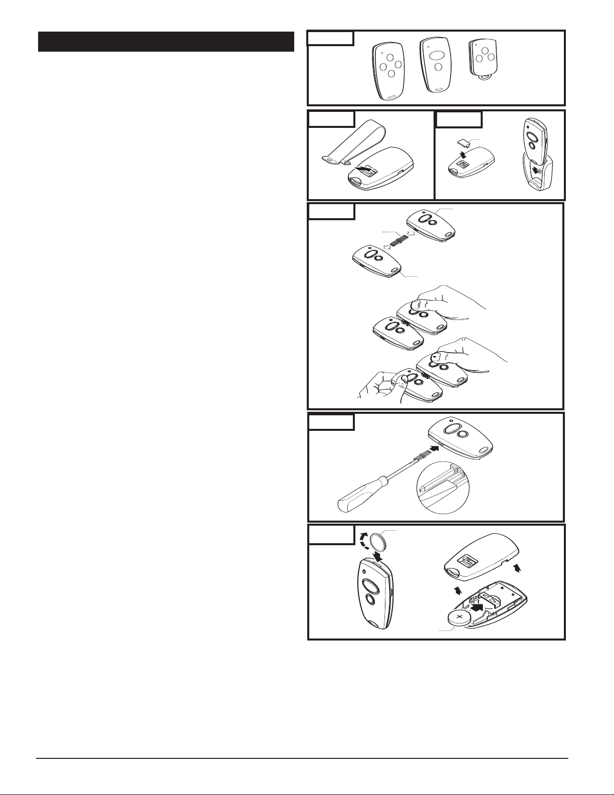
9. TRANSMITTERS
V
isor Clip
fig. 1B
V
isor Compartment
C
over
V
isor Clip
Figure 2. Battery Compartment
Coin
Battery
fig. 1C Key Ring Attachment for Micro Transmitter
Key Ring
Attachment
F
Figure 1. Mounting Plate & Visor Clip
fig. 1A
Mounting Plate
(optinal)
Transmitter with active Code
new Transmitter
Programming
Connector
Figure 3. Multiple Transmitters-Code Transfer
Transmitter with active Code
new Transmitter
Programming
Connector
new Transmitter
Programming
Connector
Visor Compartment
Cover
TRANSMITTERS (Fig. 31):
A family of state-of-the-art transmitters, each transmitter
is custom encoded with installed battery. Offered in two
styles to suit your personal preference.
■ Mini (2-or 4-channel)
■ Micro (3-channel) with keyring attachment.
TRANSMITTER MOUNTING:
The transmitters can be conveniently mounted inside your
car using the visor clip or on the wall using the mounting plate.
Visor Clip (Fig. 32)
■ Snap visor clip into transmitter.
■ Affix assembly to visor.
Note: If you do not need the visor clip, install the visor
compartment cover.
Mounting Plate (Fig. 33)
■ Secure the mounting plate to area using screw and anchor.
■ Snap the visor compartment cover.
■ Slide the transmitter into the mounting plate, which will
hold it firmly in place.
MULTIPLE TRANSMITTERS: (Fig. 34)
Each transmitter comes factory programmed with random
codes. 2-channel transmitters have 2 different random
codes, one per button, 3-channel transmitters have 3
different random codes and 4-channel transmitters have 4
different random codes, one per button. Transmitters that
are purchased separately as accessories have random codes
that must be changed in order to match the code of the
“active” transmitter, which you are already using. Below are
instructions for transferring an active code from a button on
one transmitter to a button of your choice on another
transmitter.
■
Connect the transmitter with active code to the new
transmitter using the programming connector. (Fig 49)
■ Press and hold the selected channel button on the
transmitter with the active code.
■
Press and hold the respective channel button on the new
transmitter. The light in the transmitter initially starts
blinking and then illuminates continuously after 1-2 sec.
Code transfer is completed.
■ Programming connector can be removed and both
transmitters can now be used to operate the same opener.
NOTE: For multi-button transmitters, be sure to carry out
this procedure for all the buttons you desire to use.
CHANGING THE CODE: (Fig. 35)
The transmitter factory preset code can be changed as follows:
■
Insert the programming connector into transmitter terminal.
■
Short one of the outer pins of the programming connector
with the middle pin.
■
Press and hold the respective channel button. The light will
blink rapidly for approx. 5 sec. Release the button after the
light illuminates continuously. Then remove the
programming connector.
■
Code will change in approximately 2 seconds.
■
Release button after the light illuminates continuously
remove the cable and replace the cover.
NOTE: For multi-button transmitters, be sur
this procedure for all the buttons you desire to use.
BATTERY REPLACEMENT: (Fig. 36)
■
Open the transmitter by using small coin.
e to carry out
, then
Fig. 31
Fig. 32
Fig. 33
Fig. 34
Fig. 35
Fig. 36
■
Insert a 3V battery (type CR2032) as shown.
■
Close the transmitter.
NOTE: Replace batteries with same type only.
26
Page 27
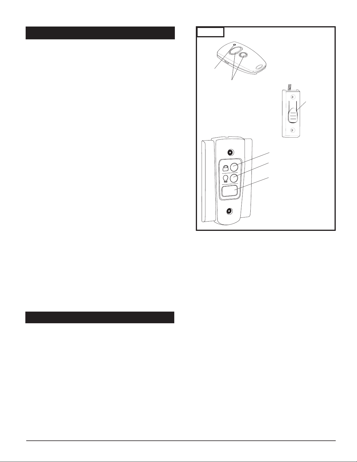
10. OPERA
C. Doorbell-Type Pushbutton
Pushbutton
Indicator Light
Buttons
A. Transmitter
L
ock/Vacation
Button
Light On/Off
Button
I
lluminated
D
oor Pushbutton
B. Wall Control Panel
Buttons
A. Transmitter
TION OF YOUR OPENER
REMOTE CONTROL TRANSMITTER:
o open or close garage door, press and hold button
■ T
(Transmitter has an indicator light that will illuminate). See
Fig. 37A. When garage door begins to move, release button.
■ To stop garage door during travel, press and hold
button until door stops, then release button.
■ To resume garage door travel after stopping, press
button again. Door begins to move in the opposite
direction.
WALL CONTROL PANEL:
■ The Door Pushbutton will light when Wall Control properly
connected (if it does not light up, review section 7-10.
“Install Wall Control” on page 14.
To open or close garage door, press and hold Illuminated
Door Pushbutton. See Fig. 37B. When garage door begins to
move, release button.
To stop garage door during travel, press and hold button
until door stops, then release button.
To resume garage door travel after stopping it, press button
again. Door begins to move in the opposite direction.
■ The Light On / Off button can be used to turn lights on or
off. When using the light On/ Off button, the automatic
timer is ignored, and the lights will remain on until the button is pressed again, or until the opener is activated and the
automatic timer begins again.
■ The Lock/Vacation button can be used to lock out all remote
control transmitters. The door can still be activated by wall
control panel or keyless entry system.
Press and hold Lock/Vacation button for 2-3 seconds. Release
button. Illuminated Door Pushbuttonand LED #7 on the
Garage Door Opener will flash continuously while lock mode
is active. To unlock opener, press and hold Lock/Vacation
button for 2-3 seconds.
DOORBELL-TYPE PUSHBUTTON:
■ To open or close garage door, press and hold Pushbutton.
See Fig. 37C. When garage door begins to move, release button.
■ To stop garage door during travel, press and hold button
until door stops, then release button.
■ To resume garage door travel after stopping it, press
and hold button until door begins to move, then
release button.
Fig. 37
OPENER LIGHTS:
■ Lights will come on whenever opener is activated.
Lights will stay on for 4 minutes and 15 seconds, or
until the Light On / Off button on the wall control
panel is pressed, whichever is sooner.
■ Lights can be turned on and off manually as
described under operation of wall control panel.
■ Lights will flash when the opener senses an obstruction either detected by the internal safety system or
the photo eye. To stop lights from flashing, remove
obstruction and operate door normally.
11. TEST SAFETY REVERSAL
The safety reversal function of your opener is an extremely
important feature of your opener. Testing this function
ensures the correct operation of your opener and door.
The reversal system test should be performed:
■ Once per month.
■ Anytime the travel or force limits are reset or changed.
Once the adjustments have been set and the door has been
run up and down twice to “learn” the new settings, you
must test the reversal system for proper operation.
■ Place a 40mm (1-1/2") high rigid object on the floor
directly in the path of the door.
■ Start the door in the downward direction and watch
what happens.
■ When door contacts the object, it should stop, reverse,
and automatically return to the fully opened
position.
■ If the door does not r
everse, reset the down travel
limit so that the door travels slightly fur
in the closed dir
ection. Then, retest the unit as
described above.
■ If the door still does not r
opener and call a ser
everse, disconnect your
vice person.
ther down
27
Page 28
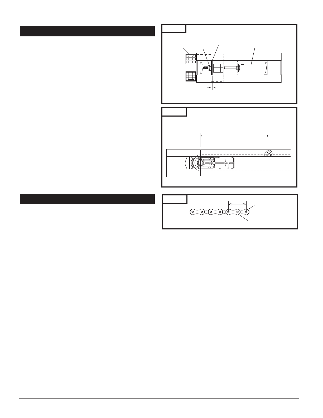
Chain Link
Chain Strap
1"
12. TENSION ADJUSTMENT
R
ail End Stop
(
Header End)
T
ension
N
ut
P
roper Space (1mm or
a
pproximately 3/64”)
P
roper Tension Adjustment
W
asher
R
oller Holder Assembly
960 mm (37 3/4")
Tab Location
Your preassembled rail comes with the tension adjusted to
y specifications. There should be no need for further
factor
adjustment. However, if exposed or subjected to unusually
harsh operating conditions, the tension may need to be
readjusted during the life of the opener.
CHECK PROPER TENSION (FIG. 38):
■ Release trolley from belt or chain, then examine the
setting of the tension adjustment at the header end of
the rail.
oper tension is set when the tension nut is tightened
■ Pr
just enough so that the washer will be spaced
approximately 1mm (3/64") from the stationary rail
end-stop arch.
■ If the gap between the washer and the rail end-stop arch
is too big or too small, the tension needs to be adjusted.
ADJUST THE TENSION:
■ To increase the tension and tighten the belt or chain, turn
the tension nut clockwise with 7/16” wrench until the
washer is spaced properly from the rail end-stop arch. See
Fig. 38.
■ Once the washer is spaced correctly, any additional
tightening will overtighten the belt or chain and may
cause damage to the system.
■ To loosen the tension, turn nut counterclockwise.
■ Reattach trolley.
Fig. 38
Fig. 39
13. RAIL LENGTH ADJUSTMENT
FOR PROFESSIONAL INSTALLERS ONLY
If your particular installation calls for a shorter rail than the
standard length provided, it is possible to shorten the rail.
NOTE: Shortening rail too much may result in door travel
length reduction and door not opening fully. This depends
on door size and configuration. Carefully plan all such
modifications before proceeding. THIS PROCEDURE SHOULD
BE PERFORMED ONLY BY A PROFESSIONAL INSTALLER FULLY
FAMILIAR WITH THIS TYPE OF OPENER SYSTEM.
TO SHORTEN BELT RAIL LENGTH:
■ Loosen belt tension as much as possible.
■ Remove screws from sprocket holder and rail end-stop.
■ Slide belt and all rail parts out of rail from header end. See
rail exploded view, Fig.41 on p. 29, for disassembly details.
■ Measure and cut off excess rail from header end.
■ Disassemble connector to expose free ends of belt.
■ Using the same measurement as the excess rail length, cut
the same amount off BOTH free ends of the belt.
■ Using rail end-stop as a guide, mark and drill two 3/16"
holes on rail sides for rail end-stop screws.
■ Reassemble belt connector, and slide all rail parts into rail
from header end according to original assembly (Fig. 38
and Fig. 39).
■ Tension belt properly (Fig. 38).
■ Before installing rail overhead, check for proper assembly
and operation by manually moving tr
rail length with trolley connected to belt.
olley up and down
Fig. 40
TO SHOR
TEN CHAIN RAIL LENGTH:
25mm (1”)
■ Loosen chain tension as much as possible.
om sprocket holder and rail end-stop.
■ Remove scr
■ Slide
ews fr
and all rail parts out of rail from header end. See
chain
rail exploded view, Fig.42 on p. 29, for disassembly details.
■ Measure and cut off excess rail from header end by 25mm
(1”) increment only.
■ Disassemble connector to expose free ends of chain.
■ Using the same measurement as the excess rail length,
remove the same amount off chain links and chain straps
from BOTH free ends of the chain (Fig. 40).
■ Using rail end-stop as a guide, mark and drill two 3/16"
holes on rail sides for rail end-stop screws.
■ Reassemble two piece connector and slide chain and all
rail parts into rail from header end according to original
assembly (Fig. 38).
■ Tension chain properly (Fig. 38).
■ Before installing rail overhead, check for proper assembly
and operation by manually moving trolley up and down
rail length with trolley connected to chain.
28
Page 29
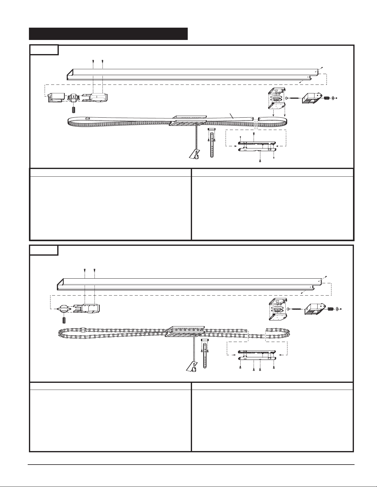
1
2
10
7
5
3
4
Header End
Powerhead End
9
8
P
owerhead End
Header End
5
6
10
8
11
3
2
1
4
7
9
14. RAIL ASSEMBLY
Fig. 41
Model#: ML-807B (7’ Door) ML-808B (8’ Door) ML-810B (10’ Door)
Part # Description
Item
——— Rail
1.
8030337 Sprocket holder assembly
2.
8008709 Belt guide
3.
8030432 Roller holder with tension bolt assembly
4.
8008503 Rail end-stop
5.
6. 8030196 Belt connector
Belt Rail Assembly
Item Part # Description
7. ——— Belt with position tab
8. 8030177 Trolley assembly (7’ Door)
8030178
8008708 Pin
9.
10. 8009465 Straight door arm
11. 8007412 Shaft adapter
Trolley assembly (8’ & 10’ Door)
Fig. 42
Chain Rail Assembly
Model#: ML-807C (7’ Door) ML-808C (8’ Door) ML-810C (10’ Door)
Item Part # Description
1. ——— Rail
2. 8030339 Sprocket holder assembly
3. 8030432 Roller holder with tension bolt assembly
4. 8008503 Rail end-stop
5. 8030234 Chain connector
6. ——— Chain with position tab
Item Part # Description
7. 8030177 Trolley assembly (7’ door)
8030178
8. 8008708 Pin
9. 8009465 Straight door arm
8007412 Shaft adapter
10.
Trolley assembly (8’ & 10’ Door)
29
Page 30
13
6
7
1
12, 12a
11
14
16, 16a
8
14
2
11
15, 15a
3
2
10
9
4
5
4
17
2, 2a
2a
1a
1a
2a
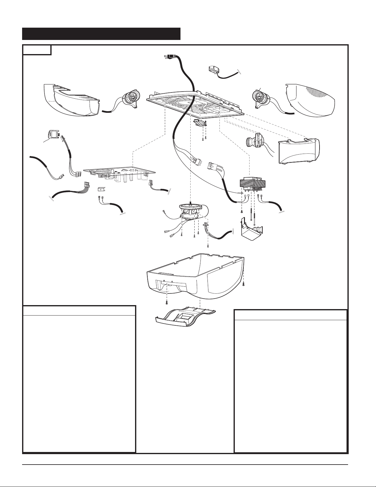
15. POWER HEAD ASSEMBLY
Fig. 43
EX-2005 - 110
Item Part # Description
1.
8007859 Lamp Lens
2.
3
4
5
6
7 8007776 Strain Relief Cover
8 65627 Logic Board
8030990 Wire Harness
——— Chassis Assembly
8054389 Reference Switch
60379 Clip
8030987 Power Cord
9 8015077 Connector Cable
10 ML-843 Modular Receiver
11 8009954 Cable (TR to LB)
12 8008474 Transformer
13 8030262 Motor Assembly
14 8055529 Sensor w/Wire Harness
15 8030422 Housing Assembly
16 8030412 Cover with Label
17 8011071 Cover
Item Part # Description
1a. 8030589 Lamp Lens
2a. 8030991 Wire Harness
3 ——— Chassis Assembly
4 8054389 Reference Switch
5 60379 Clip
6 8030987 Power Cord
7 8007776 Strain Relief Cover
8 65627 Logic Board
9 8015077 Connector Cable
10 ML-843 Modular Receiver
11 8009954 Cable (TR to LB)
12a 8003273 Transformer
13 8030262 Motor Assembly
14 8055529 Sensor w/Wire Harness
15a 8030421 Housing Assembly
16a 8030413 Cover with Label
17 8011071 Cover
EX-2007 - 110
30
Page 31
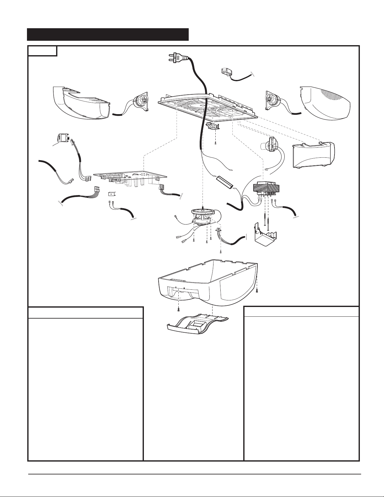
15. POWER HEAD ASSEMBLY (cont‘d)
15
6
7
1
13, 13a
11
16
18, 18a
8
16
2
11
17, 17a
3
2
10
9
4
12
4
14
5
2
2a
1a
1a
2a
Fig. 44
EX-2005 - 220
Item Part # Description
1 8007859 Lamp Lens
2 8009966 Wire Harness
3 ——— Chassis Assembly
4 8054389 Reference Switch
5 8011196 Connector
6 8009955 Power Cord
7 8007776 Strain Relief Cover
8 65627 Logic Board
9 8015077 Connector Cable
10 ML-843 Modular Receiver
11 8009954 Cable (TR to LB)
12 60379 Clip
13 8008513 Transformer
14 8011071 Cover
15 8030262 Motor Assembly
16 8055529 Sensor w/Wire Harness
17 8030410 Housing Assembly
18 8030412 Cover with Label
Item
1a.
2a.
3
4
5
6
7
8
9
10
11
12
13a. 8004852 Transformer
14 8011071 Cover
15 8030262 Motor Assembly
16 8055529 Sensor w/Wire Harness
17a. 8030411 Housing Assembly
18a. 8030413 Cover with Label
EX-2007 - 220
Part # Description
8030589 Lamp Lens
8051676 Wire Harness
——— Chassis Assembly
8054389 Reference Switch
8011196 Connector
8009955 Power Cord
8007776 Strain Relief Cover
65627 Logic Board
8015077 Connector Cable
ML-843 Modular Receiver
8009954 Cable (TR to LB)
60379 Clip
31
Page 32
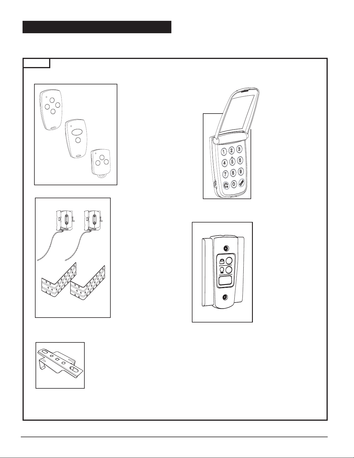
16. ACCESSORIES
The following accessories are designed to provide added convenience, satisfaction and value to your door opener system.
Accessories are available from your dealer.
Fig. 45
MINI & MICRO
TRANSMITTERS
■ Advanced multibit
technology for better
e secure signal
mor
transmission.
■ Complete with
clip.
visor
mits control up to 4
■ Per
openers or
separate
devices.
y included.
■ Batter
MINI
2 Channel Model#: M3-2432X
4 Channel Model#: M3-2434X
MICRO
3 Channel Model#: M3-3433X
,
WIRELESS KEYLESS
ENTRY SYSTEM
mits control of
■ Per
garage door opener from
outside without keys.
■ Choose own 4-digit code
for security.
■ Complete with mounting
hardware.
■ Battery Included.
Model#: M3-643X
PHOTO EYE SAFETY
SYSTEM
■ Provides a system of
protection for you and
your family
■ Designed to suit
your particular garage
environment.
■ Mounting hardware
and wiring included.
■ Easy to Install.
Model#: ML-705
SUPPORT BRACKET
■ Helps support rail 13’
and longer.
Part#: 8054214
.
ALL CONTROL
W
ANEL
P
ovides control
■ Pr
buttons for Light and
acation/Lock function.
V
■ Illuminated door
Pushbutton for easy
locating in dark.
■ Mounting har
and wir
Model#: M3-543
e included.
dware
32
Page 33
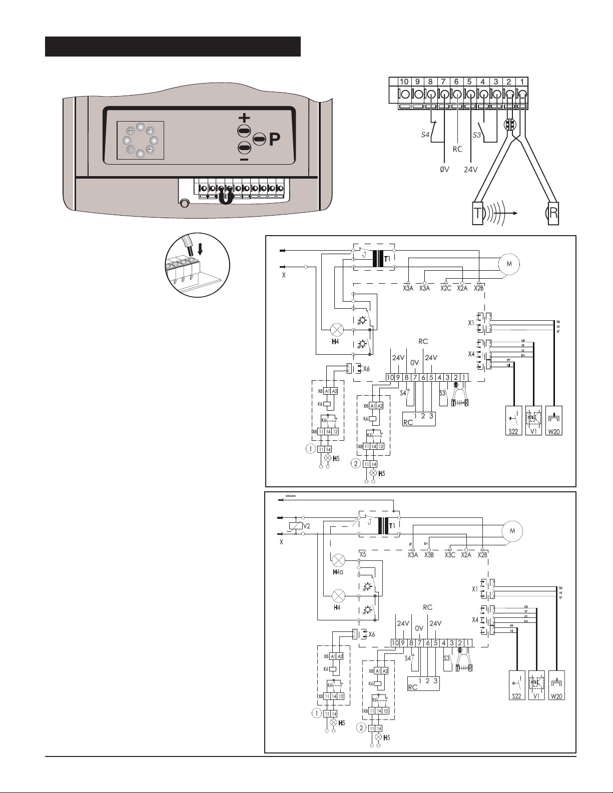
17. EXTERNAL CONNECTIONS
1
2
4
5
6
7
8
1
2
4
5
6
7
8
M motor
T1 transformer
V1 RPM sensor
S22 reference point switch
T photo-eye transmitter
R photo-eye receiver
S3 push button IMPULSE
S4 push button STOP
X1 plug 1~N 220-240V 50Hz
X3A flat cable connector dc motor
X2C ground
X2A and X2B = 24V
X6 Relay output contact 1
H4 Operator light
H5 signal light
1 internal relay (optional)
2 external relay (optional)
W20 Receiver HF module output
24V 24 VDC, 50mA max.
0V masse (ground)
RC Contact
bk black
bn brown
or orange
rd red
gr green
bl blue
ye yellow
230V/260V, 50Hz/60Hz
110V/120V
, 50Hz/60Hz
33
Page 34
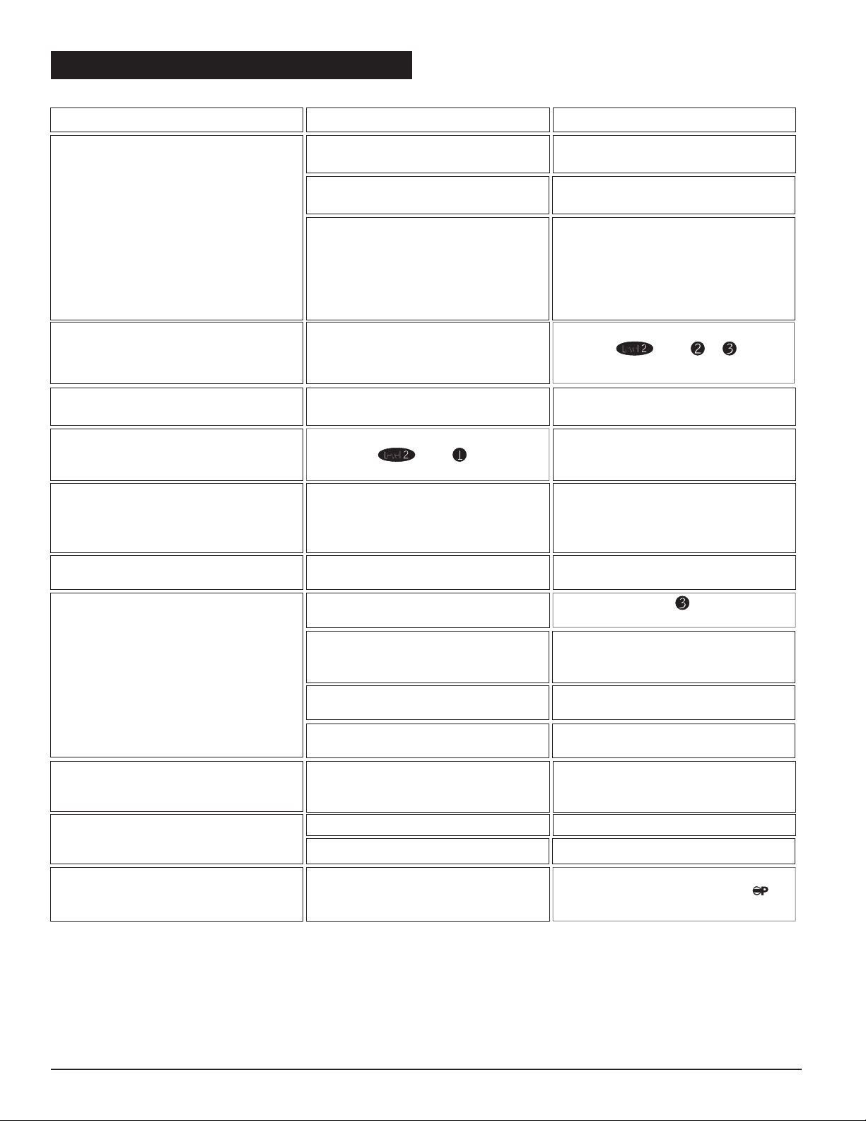
De-activate 'vacation' lock on 3-function
wall control or by briefly pressing
button on operator.
Operator is in electronic 'vacation' lockTransmitter command does not
respond but wall control does
(LED 8 on, LED 7 flashes)
Check door.Door too sluggish.
Have operator checked.RPM sensor defective.Operator only starts to run shortly.
Error 9
Insert new battery.
Flashing LED in transmitter indicates
battery condition.
Flat battery in hand transmitter.Insufficient range
of remote control (less than 5 m).
Have both components checked.Hand transmitter or control unit
defective.
Electronic aerial not connected or wrong
installation
LED 7 does not light up when
pressing transmitter button
Insert new battery.
Flashing LED in transmitter indicates
Flat battery.
Flat battery.
Check coding Menu , page 19.
Hand transmitter coding is not
consistent with receiver coding.
Transmitter problems
Connect "STOP" button.Short-circuit label removed,
but "STOP" button not connected.
No response on impulse.
Error 36
Temporarily isolate cabled key switches
or interior push buttons from control
unit. Remove plug, insert plug and look
for cable fault.
Connecting terminals for "IMPULSE"
button bridged, e.g. due to short-circuit
or wrong terminal connection.
No response on impulse.
Indicator 7 glows.
Error 36
Reprogram photo eye function or
connect photo eye.
Photo eye programmed, but not
connected (Menupage 20).
Drive only operates in "OPEN" but not in
"CLOSE" direction.
Error 15
Remove obstruction or have photo eye
checked.
External photo eye defective or interrup-
ted.
Indicator 6 flashes.
Error 6 or 15
Re-set automatic cut-out to be less
sensitive ( Menu &
page 20,21). Ensure door moves easily
Automatic cut-out set too sensitively.
Door operation too sluggish.
Door blocks.
Indicator 6 flashes. Error 10 or 28
Cut off mains supply to operator.
Remove lamp cover and motor cover.
Unscrew control unit, pull slightly
forward and withdraw the connecting
plug. Remove control unit and have it
checked.
Defective control unit.
Allow mains transformer to cool down.Thermal protection in mains transformer
activated.
Check mains supply.
Check electric socket.
No voltage.Indicator 8 does not glow.
RemedyCauseFault
T
18. TROUBLESHOOTING
34
Page 35
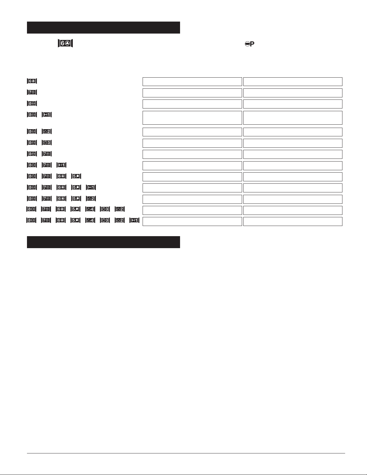
E
RROR MESSAGES
When LED is blinking the error message can be retrieved by pressing briefly.
The total sum of numbers in blinking LEDs indicate so-called error number.
LED flashes erratically Error number
+
+
+
+
++
+++
++++
++++
++++++
+++++++
36
35
28
27
26
16
15
11
10
9
8
7
6
Fault
Electronics defective
Excess travel stop is active
Defective RPM sensor
Anti-lock system actuaed
P
hoto eye safety system actuated
NC contact (Te rminal 7&8) broken
Learned power limit is active
Response sensitivity of power limit
Voltage monitoring is active
Power limit self-monitoring unit not o.k.
Photo eye self-monitoring unit not o.k.
Power limit is active
Reference point switch defective
P
rogramming not complete
19. ERROR MESSAGES
20. TECHNICAL SPECIFICATIONS
EX-2005 and EX-2007 Series
Garage Door Opener
Connected loads:
230 V
250 W (in operation with lighting)
120 V
210 W (one light system)
Door travel speed:
0.14 m/s with "soft" start and "soft" stop
Push and pull force:
500 N
700 N
Excess travel stop:
88 secs.
Lighting:
40 W E14 -230V Application
60 W E26 -120V Application
Control voltage:
Low voltage below 24 V DC.
Automatic timer:
With additional relay for signal lights
connection and photo eye to monitor the
through-traffic area (both items available as
accessories).
Warning phase adjustable from 2 to 70
seconds.
Open phase adjustable from 5 - 255
seconds.
Automatic cut-out:
Electronic power limit through microprocessor
and power sensor.
Anti-Block system:
Through microprocessor and RPM sensor.
Device to prevent forced opening of door:
Electronic back-drive prevention by
permanent protection of the closed door position.Door will automatic close after
ca. 1cm detected unauthorized reverse movement.
Protection category:
For dry buildings only.
35
Page 36
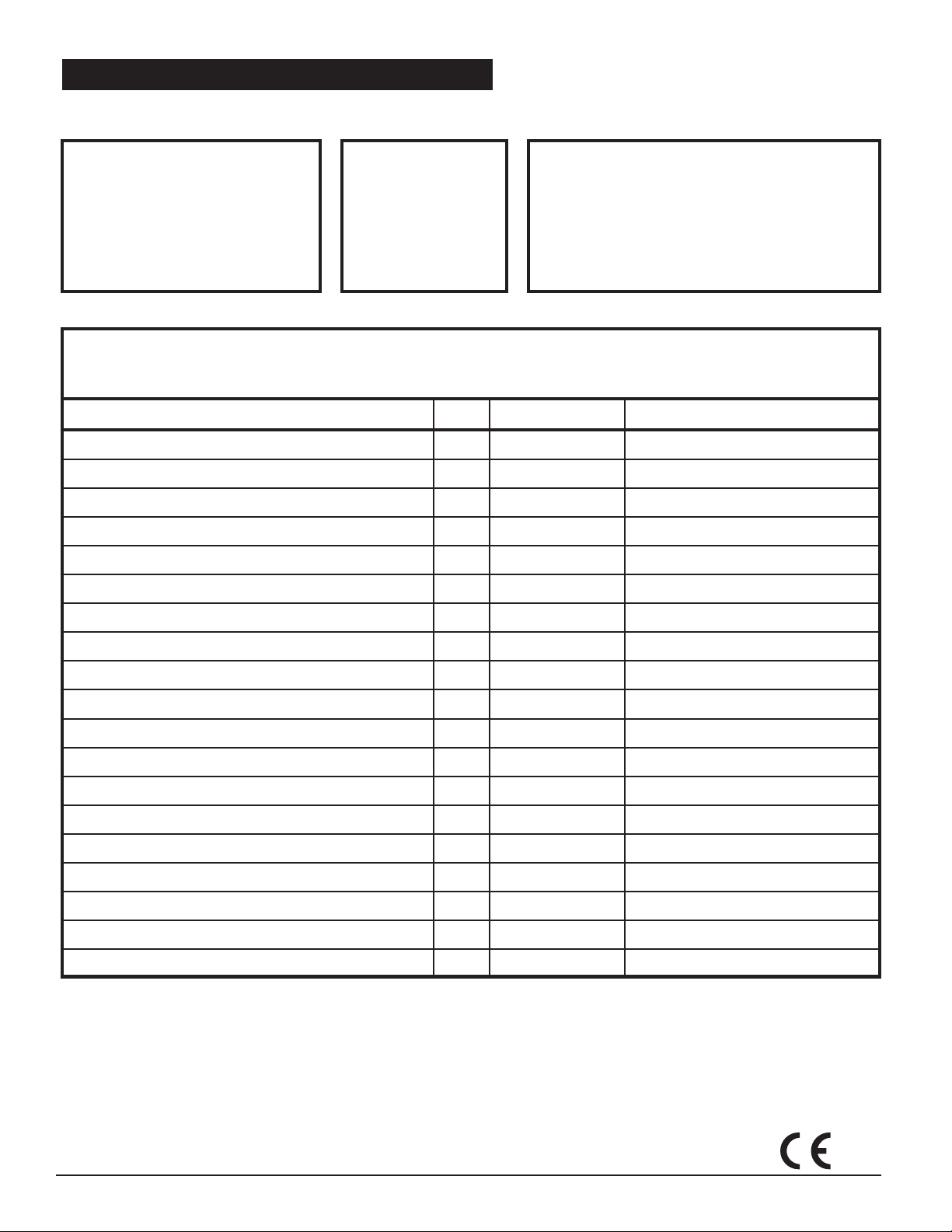
21. MAINTENANCE AND ADJUSTMENTS RECORD
To ensure continued safe operation and extended life of your opener system, periodic checking for proper operation is
necessary. Occasional maintenance and readjustment of your system may also be needed.
■ Check reversal system by performing “SAFETY
MONTHLY
REVERSAL TEST”
■ Check proper operation of door by
manually moving door open and closed.
If door binds or sticks, or is out of balance
call for garage door service.
■ Check and test photo eye safety system
as described in this manual.
described in this manual.
ONCE EVERY
YEAR:
■ Keep
door rollers, hinges,
and
bearings properly
lubricated by following
recommended door
instructions or contacting
a door service company
in your ar
ea.
■ Readjust opener travel limits and force settings as necessary
AS NEEDED:
— due to cold weather
The convenient adjustment instruction label on the opener
can be used for any periodic adjustments needed.
■ Check and readjust belt tension, if necessary, in the unlikely event
that it loses its proper tension during the life of the opener.
■ Always check the r
limits or forces. A door opener that is not checked could
possibly be out of adjustment and be dangerous.
eversal system after any adjustment of travel
, normal wear of door, etc.
Good maintenance of your garage door is an imperative requirement. Not only will it prolong the life of the door
and the opener, but more importantly, it assures your safety and that of others. Use the form below to record the
monthly, yearly, and “as needed” maintenance.
Maintenance Steps Date Performed By Comments
If you run out of Maintenance Record lines, please make yourself another record sheet.
© Copyright 2004 All Rights Reserved.
No part of this manual may be reproduced without our prior written approval.
We reserve the right to alter details in the interests of progress.
EN 55011
EN 50081
EN 50082
ETS 300220
36 Part #: 70229 Printed in the U.S.A. Version 05/04
 Loading...