

Page 1

Betriebsanleitung Steuerung CS 310
D
Torsteuerung CS 310 / Rev.B 1.0 – 1
Page 2
1. Inhaltsangabe
2. Angaben zum Dokument
1. Inhaltsangabe 2
2. Angaben zum Dokument 2
3. Allgemeine Sicherheitshinweise 3
4. Produktübersicht 4
5. Inbetriebnahme 6
6. Einstellen der Endlagen 13
7. Programmierung mit dem LCD-Monitor 16
8. Navigator (nur LCD-Monitor) 18
9. Funktionsübersichten 20
10. Fehleranzeige und Behebung 28
11. Technische Daten 31
12. Wartung 32
13. EG-Einbauerklärung 33
14. Anhang 34
Originalbetriebsanleitung
− Urheberrechtlich geschützt.
− Nachdruck, auch auszugsweise, nur mit unserer
Genehmigung.
− Änderungen, die dem technischen Fortschritt dienen,
vorbehalten.
− Alle Maßangaben in Millimeter.
− Darstellungen sind nicht maßstabsgetreu.
Symbolerklärung
GEFAHR!
Sicherheitshinweis auf eine Gefahr, die unmittelbar zu Tod
oder zu schweren Verletzungen führt.
WARNUNG!
Sicherheitshinweis auf eine Gefahr, die zu Tod oder zu
schweren Verletzungen führen kann.
VORSICHT!
Sicherheitshinweis auf eine Gefahr, die zu leichten bis
mittelschweren Verletzungen führen kann.
HINWEIS
Sicherheitshinweis auf eine Gefahr, die zu Beschädigungen
oder zur Zerstörung des Produkts führen kann.
KONTROLLE
Hinweis auf eine durchzuführende Kontrolle.
VERWEIS
Verweis auf separate Dokumente die zu beachten sind.
Handlungsaufforderung
− Liste, Aufzählung
2 – Torsteuerung CS 310 / Rev.B 1.0
Verweis auf andere Stellen in diesem Dokument
Page 3

3. Allgemeine Sicherheitshinweise
D
GEFAHR!
Lebensgefahr durch Nichtbeachtung der
Dokumentation!
Beachten Sie alle Sicherheitshinweise in diesem
Dokument.
Gewährleistung
Eine Gewährleistung in Bezug auf Funktion und Sicherheit
erfolgt nur, wenn die Warn- und Sicherheitshinweise in dieser
Betriebsanleitung beachtet werden.
Für Personen- oder Sachschäden, die durch Nichtbeachtung
der Warn- und Sicherheitshinweise eintreten, haftet die Marantec GmbH + Co.KG nicht.
Für Schäden, die durch die Verwendung von nicht zugelassenen Ersatzteilen und Zubehör entstehen, ist jede Haftung
und Gewährleistung seitens Marantec ausgeschlossen.
Bestimmungsgemäße Verwendung
Die Steuerung CS 310 ist ausschließlich für die Steuerung von
Toranlagen mit digitalen oder mechanischen Endlagensystemen bestimmt.
Zielgruppe
Nur qualizierte und geschulte Elektrofachkräfte dürfen die
Steuerung anschließen, programmieren und warten.
Qualizierte und geschulte Elektrofachkräfte erfüllen folgende
Anforderungen:
− Kenntnis der allgemeinen und speziellen Sicherheits- und
Unfallverhütungsvorschriften,
− Kenntnis der einschlägigen elektrotechnischen Vorschriften,
− Ausbildung in Gebrauch und Pege angemessener
Sicherheitsausrüstung,
− Fähigkeit, Gefahren in Zusammenhang mit Elektrizität zu
erkennen.
Hinweise zu Montage und Anschluss
− Vor elektrischen Arbeiten muss die Anlage von der Strom-
versorgung getrennt werden. Während der Arbeiten muss
sichergestellt werden, dass die Stromversorgung unterbrochen bleibt.
− Die örtlichen Schutzbestimmungen sind zu beachten.
Hinweise zum Betrieb
− Kinder nicht mit fest montierten Regel- oder Steuereinrich-
tungen spielen lassen.
− Fernsteuerungen außerhalb der Reichweite von Kindern
halten.
Prüfgrundlagen und Vorschriften
Bei Anschluss, Programmierung und Wartung müssen
folgende Vorschriften beachtet werden (ohne Anspruch auf
Vollständigkeit).
Bauproduktnormen
− EN 13241-1 (Produkte ohne Feuer und Rauchschutzeigen-
schaften)
− EN 12445 (Nutzungssicherheit kraftbetätigter Tore -
Prüfverfahren)
− EN 12453 (Nutzungssicherheit kraftbetätigter Tore -
Anforderungen)
− EN 12978 (Schutzeinrichtungen für kraftbetätigte Tore -
Anforderungen und Prüfverfahren)
EMV
− EN 55014-1 (Störaussendung Haushaltsgeräte)
− EN 61000-3-2 (Rückwirkungen in Strom versorgungsnetzen
– Oberschwingungen)
− EN 61000-3-3 (Rückwirkungen in Strom versorgungsnetzen
– Spannungsschwankungen)
− DIN EN 61000-6-2 (Elektromagnetische Verträglichkeit
(EMV) - Teil 6-2: Fachgrundnormen – Störfestigkeit für
Industriebereiche)
− DIN EN 61000-6-3 (Elektromagnetische Verträglichkeit
(EMV) - Teil 6-3: Fachgrundnormen – Störaussendung für
Wohnbereich, Geschäfts- und Gewerbebereiche sowie
Kleinbetriebe)
Maschinenrichtlinie
− EN 60204-1 (Sicherheit von Maschinen, elektrische Ausrü-
stung von Maschinen; Teil 1: Allgemeine Anforderungen)
− EN ISO 12100 (Sicherheit von Maschinen – Allgemeine
Gestaltungsleitsätze - Risikobeurteilung und Risikominderung)
Torsteuerung CS 310 / Rev.B 1.0 – 3
Page 4

Allgemeine Sicherheitshinweise
4. Produktübersicht
Niederspannung
− DIN EN 60335-1 (Sicherheit elektrischer Geräte für den
Hausgebrauch und ähnliche Zwecke - Teil 1: Allgemeine
Anforderungen)
− DIN EN 60335-2-103 (Sicherheit elektrischer Geräte für den
Hausgebrauch und ähnliche Zwecke - Teil 2-103: Besondere
Anforderungen für Antriebe für Tore, Türen und Fenster)
Ausschuss für Arbeitsstätten (ASTA)
− ASR A1.7 (Technische Regeln für Arbeitsstätten „Türen und
Tore“)
4.1 Varianten
Folgende Liefervarianten der Steuerung CS 310 sind möglich:
− Steuerung CS 310 mit LCD-Monitor
− Steuerung CS 310 mit LCD-Monitor im Gehäuse
− Steuerung CS 310 mit LCD-Graphik-Monitor
− Steuerung CS 310 mit LCD-Graphik-Monitor im Gehäuse
− Steuerung CS 310 ohne LCD-Monitor (Monitor wird für alle
Einstellungen, außer der Endlageneinstellung, benötigt)
Alle genannten Varianten können mit einer steckbaren
Wochenzeitschaltuhr, einem steckbarem Funkempfänger und
einem steckbaren Übertragungssystem (für Opto-Sensoren)
ausgestattet werden.
Folgende Liefervarianten der Gehäuse sind möglich:
− Gehäuse mit 3-fach-Taster CS
− Gehäuse mit 3-fach-Taster KDT
− Gehäuse mit Schlüsselschalter EIN/AUS
− Gehäuse mit Hauptschalter
− Gehäuse mit Not-Aus
Die Betriebsanleitung beschreibt die Anschluss möglichkeiten
und Programmierung der Varianten:
− Steuerung CS 310 mit aufgesteckter LCD-Display-Platine
4 – Torsteuerung CS 310 / Rev.B 1.0
Page 5
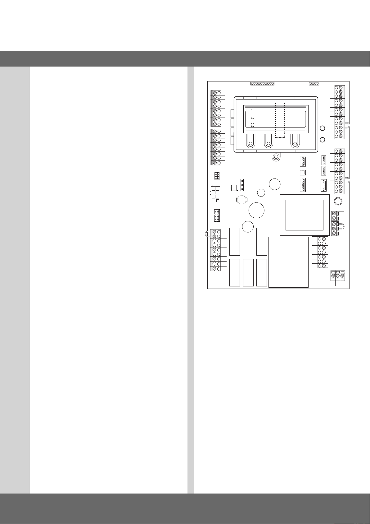
4.2 Grundplatine CS 310
(mit aufgestecktem LCD-Display-Monitor)
Erklärung:
X1: Klemmleiste Netzanschluss
X2: Klemmleiste Motor
X3: Klemmleiste Befehlsgeräte
X4: Klemmleiste Sicherheitselemente
X5: Klemmleiste Relais
X6: Steckleiste für internen EIN-AUS-Schalter
X7: Steckleiste für internen 3-fach-Taster
X8: Stecksockel für Monitor
(Unter Monitor)
X9: Steckleiste für Funkempfänger
X10: Steckleiste für Wochenzeit schaltuhr
X11: Steckleiste für digitales Endlagensystem
X12: Steckanschluss für externen Funkempfänger
X13: Steckleiste für 3-fach-Taster CS
X14: Schnittstelle RS 485
- Anschluss Taster CSI
- Anschluss Display RS 485
X15: Anschluss für mechanisches Endlagensystem
X16: Anschluss BUS-System (MS BUS)
X17: Anschluss BUS-System (MS BUS)
X18: Schnittstelle Frequenzumrichter
X19: Versorgung externer Geräte
230V / 50 Hz abgesichert über F1 (1 A träge)
X20: Steckleiste für Übertragungssystem
H4: Betriebsbereitschaft
leuchtet bei funktionierender Steuerung
H6: Zustandsanzeige
leuchtet bei Betätigung der Sicherheitseinrichtungen
oder bei Fehlern
S1: Programmiertaste (+)
(Unter Monitor)
S2: Programmiertaste (–)
(Unter Monitor)
S3: Programmiertaste (P)
(Unter Monitor)
X5
X2
1
2
3
4
5
6
7
8
1
2
3
4
5
6
7
8
X14
X11
X18
B1
B2
W
V
U
X15
X10
S1
S2
S3
X20
X8
X12
X6
X7
X9
X17
X16
X13
N
L3
L2
L1
H4
H6
X4
12
11
10
9
8
7
6
5
4
3
2
1
10
9
8
7
6
5
4
3
2
1
X19
X1
PEPEPE
D
X3
F1
L
N
Torsteuerung CS 310 / Rev.B 1.0 – 5
Page 6
5. Inbetriebnahme
5.1 Allgemeines
Um eine einwandfreie Funktion zu gewährleisten müssen die
folgenden Punkte zutreffen:
− Das Tor ist montiert und funktions fähig.
− Der Getriebemotor ist montiert und funktionsbereit.
− Die Befehls- und Sicherheitsgeräte sind montiert und
funktionsbereit.
− Das Steuerungsgehäuse mit der Steuerung CS 310 ist
montiert.
VERWEIS
Für die Montage des Tores, des Getriebemotors und der
Befehls- und Sicherheitsgeräte sind die Anleitungen der
jeweiligen Hersteller zu berücksichtigen.
5.2 Netzanschluss
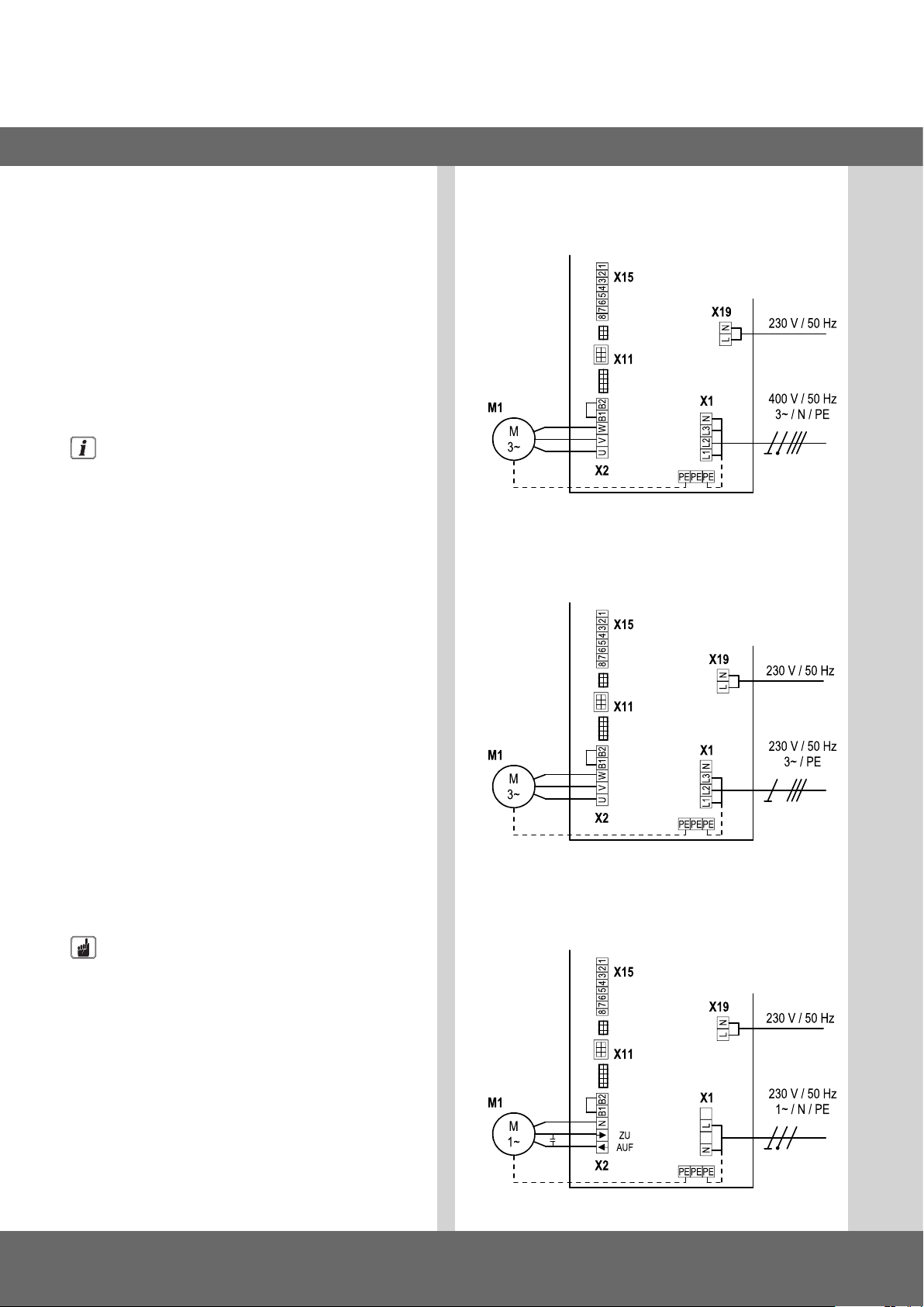
Detailschaltplan Netzanschluss und Motoranschluss
(400 V / 3-phasig)
Detailschaltplan Netzanschluss und Motoranschluss
(230 V / 3-phasig)
Voraussetzungen
Um die Funktion der Steuerung zu gewährleisten, müssen die
folgenden Punkte zutreffen:
- Die Netzspannung muss der Angabe auf dem Typenschild
entsprechen.
- Die Netzspannung muss mit der Spannung des Antriebs
übereinstimmen.
- Bei Drehstrom muss ein rechts drehendes Drehfeld vorliegen.
- Bei Festanschluss muss ein allpoliger Hauptschalter verwendet werden.
- Bei Drehstromanschluss dürfen nur 3er Blocksicherungsautomaten (10 A) verwendet werden.
HINWEIS
Funktionsstörungen durch unsachgemäße Montage
der Steuerung!
Vor dem erstmaligem Einschalten der Steuerung muss nach
Komplettierung der Verdrahtung geprüft werden, ob alle
Motoranschlüsse steuerungs- und motorseitig festgezogen
sind. Alle Steuerspannungseingänge sind galvanisch gegenüber der Versorgung getrennt.
Detailschaltplan Netzanschluss und Motoranschluss
(230 V / 1-phasig)
6 – Torsteuerung CS 310 / Rev.B 1.0
Page 7
D
Erklärung:
M1: Motor
X1: Klemmleiste Netzanschluss
X2: Klemmleiste Motor
X11: Steckleiste für digitales Endlagensystem mit
Sicherheitskreis (STOPP-KETTE)
X15: Klemmleiste für mechanische Endschalter
(Sicherheitskreis an X2 / B1-B2)
X19 Anschluss für die Versorgung externer Geräte
Anschluss:
Digitales Endlagensystem, bzw. mechanische Endschalter an
die Steuerung anschließen.
Steuerung an den Motor anschließen.
Steuerung an das Stromnetz anschließen.
Steuerung an den Motor anschließen.
Kabelgruppen sind unmittelbar vor der jeweiligen Klemme
mit einem Kabelbinder zu sichern.
& „11. Technische Daten“ auf Seite 31
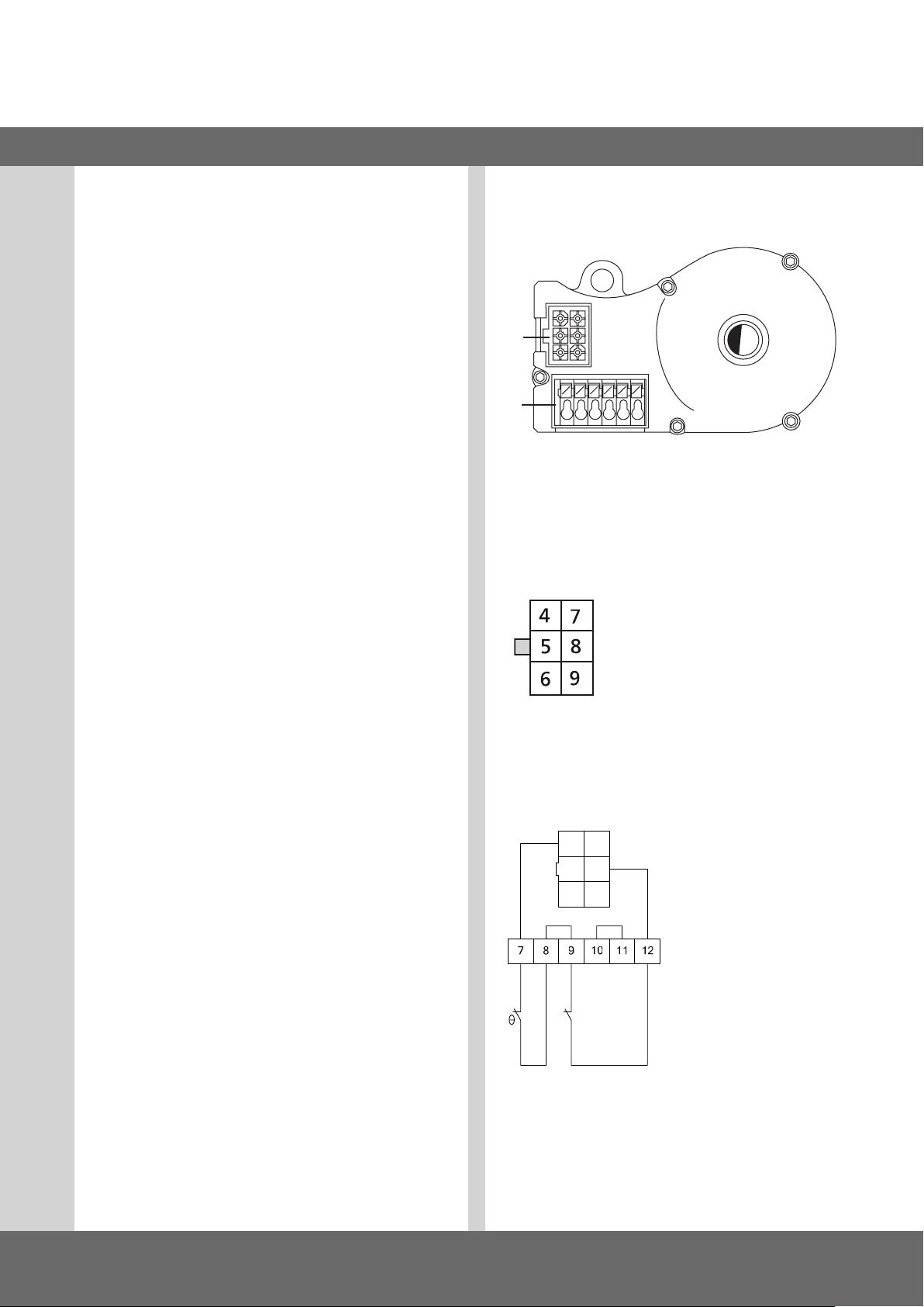
5.3 Anschlussbelegung Absolutwertgeber
(Steckklemme X11)
A
B
A: AWG-Stecker
B: AWG-Steckklemme
Steckklemme X11 (an Anschluss A)
Die Zahlen auf dem Stecker sind
gleichzeitig die Adernummern:
4: Sicherheitskette Eingang
5: RS 485 B
6: GND
7: RS485 A
8: Sicherheitskette Ausgang
9: 12V
DC
Steckklemme B (nur Absolutwertgeber)
C: Thermoelement im
Antrieb
D: Nothandbetätigung
(Notkurbel oder Notkette)
C D
Bei der ersten Inbetriebnahme wird das angeschlossene
Endlagensystem automatisch erkannt. Bei einem späteren
Wechsel muss das jeweilige Endlagensystem über eine
Parametereinstellung in der Betriebsart Eingabe gewählt
werden.
Torsteuerung CS 310 / Rev.B 1.0 – 7
Page 8
Inbetriebnahme
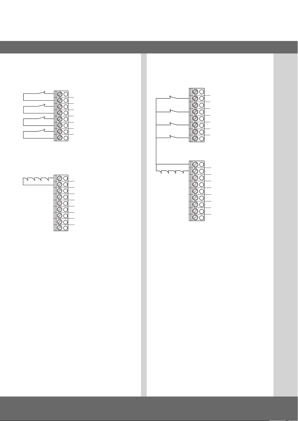
5.4 Anschlussbelegung mechanische
Endschalter (Klemme X15 und X2)
Klemmleiste X15
1
1
2
2
3
4
3
5
6
4
7
8
Klemmleiste X2
5
7
6
8
B2
B1
W
Anschlussbeispiel für 6-Ader Lösung
Klemmleiste X15 und X2
1
1
2
2
3
4
3
5
6
4
7
8
B2
B1
5
8
6
7
W
V
U
V
1
Endschalter AUF
2
Endschalter ZU
3
Vorendschalter AUF
4
Vorendschalter ZU
5
Thermoschutz Motor
6
Notbedienung (Öffner)
7
Sicherheitsendschalter ZU
8
Sicherheitsendschalter AUF
Bei der ersten Inbetriebnahme wird das angeschlossene
Endlagensystem automatisch erkannt. Bei einem späteren
Wechsel muss das jeweilige Endlagensystem über eine
Parametereinstellung in der Betriebsart Eingabe gewählt
werden.
U
8 – Torsteuerung CS 310 / Rev.B 1.0
Page 9
D
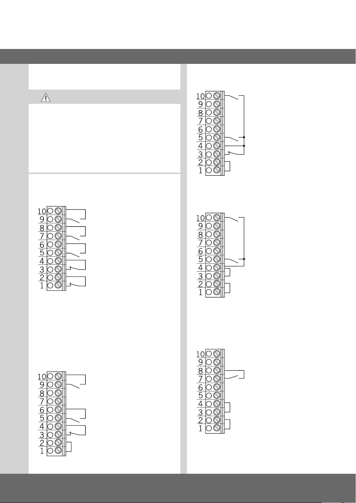
5.5 Anschlussbelegung Befehlsgeräte
VORSICHT!
Verletzungsgefahr durch unkontrollierte
Torbewegung!
Montieren Sie Befehlsgeräte für den Totmannbetrieb
in direkter Sichtweite vom Tor, aber außerhalb des
Gefahrenbereiches für den Bediener.
Falls das Befehlsgerät kein Schlüsselschalter ist:
Montieren Sie es in einer Höhe von mindestens 1,5 m.
Montieren Sie es unzugänglich für die Öffentlichkeit.
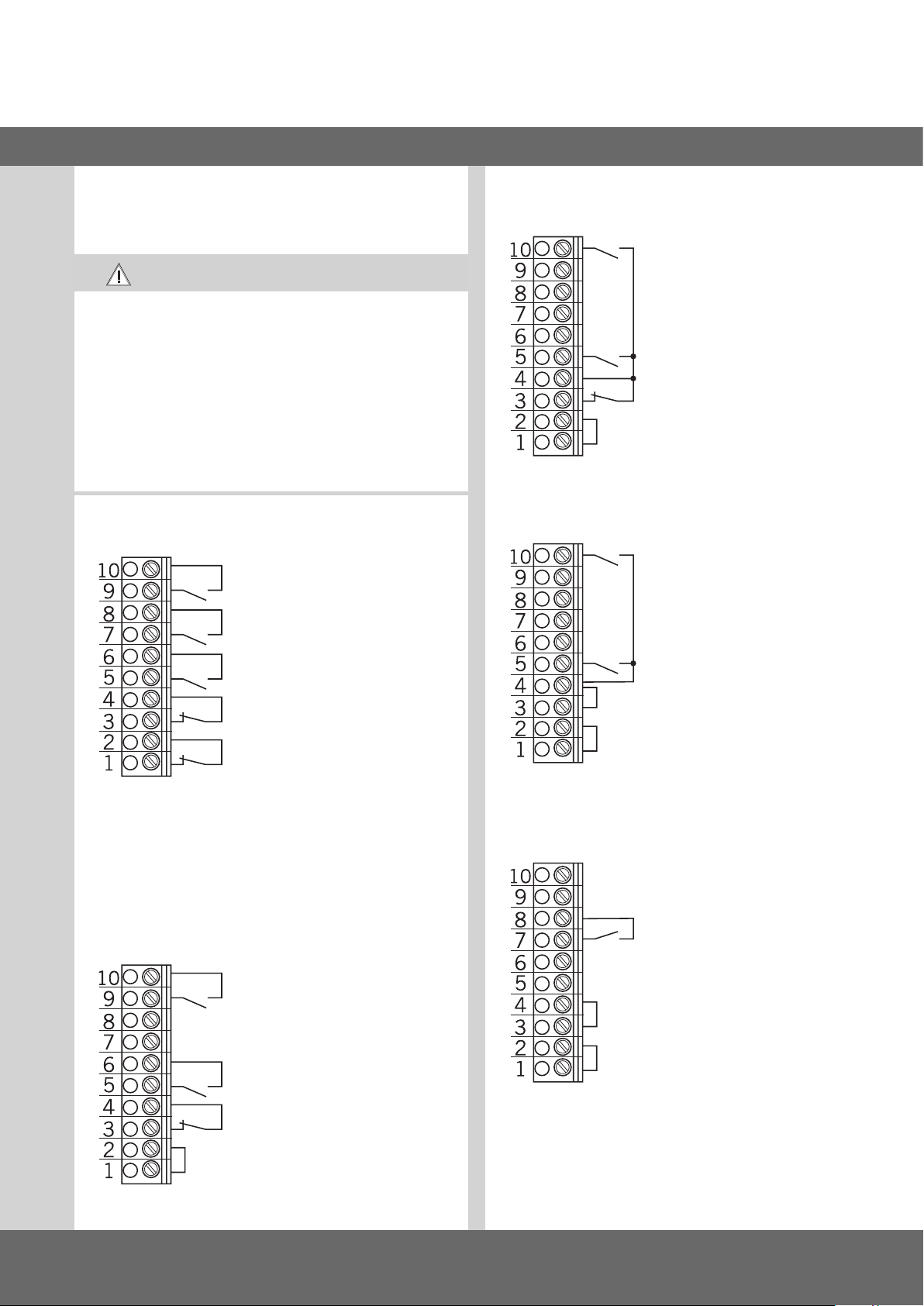
Klemmleiste X3
- Taster ZU
- Taster Impuls1
Taster AUF / STOPP / ZU
4-Ader Lösung
- Taster ZU
- Taster AUF
- Taster STOPP
Schlüsselschalter AUF / ZU
- ZU
- Taster AUF
- Taster STOPP
- Not Aus, Schlaffseilschalter,
Schlupftürkontakt, Einzugsicherung
5.6 Anschlussbeispiele Befehlsgeräte
(Klemmleiste X3)
Taster AUF / STOPP / ZU
6-Ader Lösung
- Taster ZU
- Taster AUF
- AUF
Impulstaster
Folgesteuerung
- Taster Impuls
- Taster STOPP
Torsteuerung CS 310 / Rev.B 1.0 – 9
Page 10
1
Inbetriebnahme
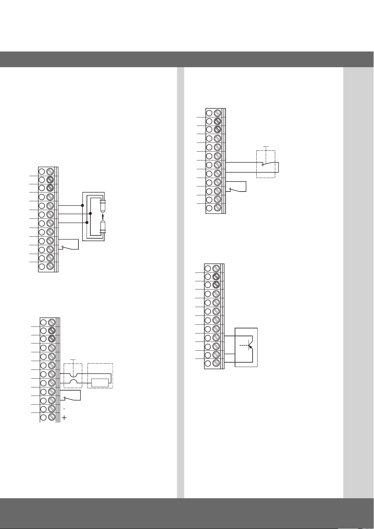
5.7 Anschlussbelegung Sicherheitsgeräte
Beim ersten Anschließen wird das System der Schließkantensicherung automatisch erkannt. Bei einem späteren Wechsel
muss das jeweilige System über eine Parametereinstellung in
der Betriebsart Eingabe gewählt werden.
Klemmleiste X4
für opto-elektronische Schließkantensicherung
12
11
10
9
8
7
wt
gr
br
- Schließkanten sicherung
OPTO
6
5
4
3
2
1
Klemmleiste X4
für 8,2 kOhm-Schließkantensicherung
12
11
10
-
+
- Durchfahrt
Lichtschranke
- 24 V DC / 250 mA
1
2
9
8
7
6
5
4
3
8k2
- Schließkantensicherung
- Durchfahrt
Lichtschranke
1
2
- 24 V DC / 250 mA
Klemmleiste X4
für pneumatische Schließkantensicherung - DW:
- Testung automatisch aktiv
12
11
10
9
8
7
6
- Schließkantensicherung
5
4
3
2
1
Klemmleiste X4
für 3-Draht Lichtschranke
12
11
10
-
+
- Durchfahrt
Lichtschranke
- 24 V DC / 250 mA
1
2
9
8
7
6
5
4
- Lichtschranke 3-Draht
3
2
GND
24V
1
2
1
wirkt in Abwärtsrichtung
2
für externe Schaltgeräte
(Anschluss an Klemme 1 und 2)
wt: weiß
gr: grün
br: braun
10 – Torsteuerung CS 310 / Rev.B 1.0
Page 11
D
**
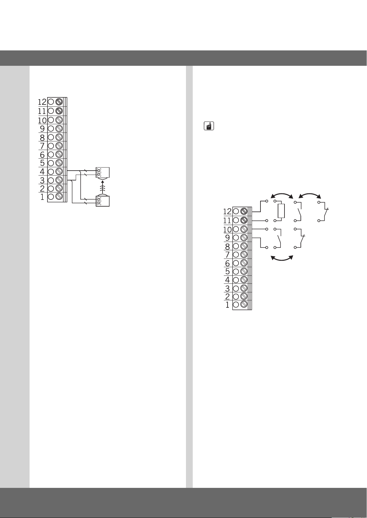
Klemmleiste X4
für MFZ 2-Draht Lichtschranke
2121
R
T
R: Empfänger
T: Sender
Beim ersten Anschließen wird das System der Schließkantensicherung automatisch erkannt. Bei einem späteren Wechsel
muss das jeweilige System über eine Parametereinstellung in
der Betriebsart Eingabe gewählt werden.
Klemmleiste X4
Programmierbare Eingänge
Eingang 1 : Klemme 9 + 10
Eingang 2 : Klemme 11 + 12
HINWEIS
Gefahr von Sachschaden der Platine durch falschen
Anschluss!
Die Eingänge 1 und 2 besitzen unterschiedliches Bezugspotenzial und dürfen nicht von einem gemeinsamen
Potenzial betrieben werden!
IN2
8K2
12V
IN1
24V
*
* wahlweise
Die Art der Beschaltung richtet sich nach den Parametereinstellungen für die beiden Eingänge in der Betriebsart
EINGABE.
Torsteuerung CS 310 / Rev.B 1.0 – 11
Page 12
Inbetriebnahme
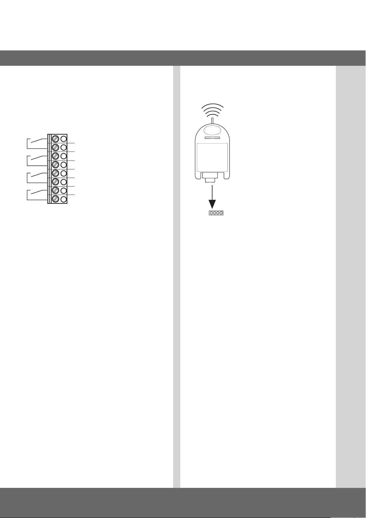
5.8 Anschlussbelegung Relaisausgänge
Klemmleiste X5
Potentialfreie Schaltkontakte
− Funktionszuweisung in der Betriebsart EINGABE
− Einstellung für jedes einzelne Relais
1
- Relais 1
2
3
- Relais 2
4
5
- Relais 3
6
7
- Relais 4
8
5.9 CS-Funk
Klemmleiste X9
Anschließen
Stecken Sie den Steckempfänger auf
den Stecksockel X9.
Sendercodes einlernen
Drücken sie kurz die Programmiertaste
(< 1,6 Sekunden). Der Programmiermodus
wird aktiviert. Die LED blinkt.
Drücken sie die Kanaltaste ihres
Senders.
Hat die Funksteuerung den Sendercode
X9
Sie können insgesamt 15 Sendercodes einlernen. Sind alle
Speicherplätze belegt, blinkt die LED sehr schnell.
gespeichert, leuchtet die LED für ca. 4
Sekunden.
Gezieltes Löschen eines Sendercodes
Drücken sie kurz die Programmiertaste (< 1,6 Sekunden).
Der Programmiermodus wird aktiviert. Die LED blinkt.
Halten sie die Programmiertaste länger als 1,6 Sekunden
gedrückt. Der Löschmodus wird aktiviert. Die LED blinkt sehr
schnell.
Drücken sie die gewünschte Kanaltaste ihres Senders.
Wenn die LED für ca. 4 Sekunden leuchtet, wurde der entsprechende Sendercode gelöscht.
Durch kurzes Drücken der Programmiertaste können sie den
Löschvorgang abbrechen.
Reset (Speicher komplett löschen)
Drücken sie kurz die Programmiertaste (< 1,6 Sekunden).
Der Programmiermodus ist aktiviert. Die LED blinkt.
Halten sie die Programmiertaste länger als 1,6 Sekunden
gedrückt.
Der Löschmodus wird aktiviert. Die LED blinkt sehr schnell.
Drücken sie die Programmiertaste erneut länger als
1,6 Sekunden.
Wenn die LED für ca. 4 Sekunden leuchtet, wurden alle
Speicherplätze gelöscht.
12 – Torsteuerung CS 310 / Rev.B 1.0
Durch kurzes Drücken der Programmiertaste können sie den
Löschvorgang abbrechen.
Page 13

6. Einstellen der Endlagen
D
6.1 Überprüfung der Abtriebsdrehrichtung /
Fahrtrichtung
Wechsel in die Betriebsart Justierung
Drücken der Taste (P) bis JUSTIERUNG erscheint.
Überprüfung der Fahrtrichtung
Drücken der Taste (+) das Tor muss Öffnen, bzw. Drücken
der Taste (-) das Tor muss Schließen.
Ist das korrekt, mit der Einstellung der Endlagen fortfahren.
Ändern der Abtriebsdrehrichtung
Muss die Abtriebsdrehrichtung angepasst werden, wie folgt
vorgehen.
Gleichzeitiges Drücken der Tasten (+) und (-) für
> 5 Sekunden. Das Display zeigt an „DREHFELD“.
Eventuell gespeicherte Endlagen werden gelöscht.
Mit der Einstellung der Endlagen fortfahren.
6.2 Einstellung der elektronischen Endlage
über die Einstelltaster auf der Platine
Wechsel in die Betriebsart Justierung
Drücken der Taste (P) für ca. 5 Sekunden.
Die rote LED blinkt langsam.
Einstellen der Endlage AUF
Tor durch Drücken der Taste (AUF/ZU) in die gewünschte
Endlage AUF fahren.
Endlage abspeichern durch Drücken der Taste (P) und
zusätzliches Drücken der Taste (AUF).
Die rote LED blinkt schnell für ca. 1 Sekunde.
Einstellen der Endlage ZU
Tor durch Drücken der Taste (AUF/ZU) in die gewünschte
Endlage ZU fahren.
Endlage abspeichern durch Drücken der Taste (P) und
zusätzliches Drücken der Taste (ZU).
Die rote LED blinkt schnell für ca. 1 Sekunde.
Der Justiermodus wird automatisch verlassen.
Die rote LED erlischt.
Zu beachten
− Der Justiermodus wird automatisch nach ca. 10 Sekunden
verlassen, wenn keine Taste gedrückt wird.
− Beim erstmaligen Justieren müssen beide Endlagen einge-
lernt werden, ansonsten ist kein Normalbetrieb möglich.
− Wenn eine Endlage korrigiert wird, so kann nach Einlernen
der speziellen Endlage das Justiermenü durch Drücken der
Taste (P) verlassen werden.
− Nach Programmieren der Endschalter wird die Laufzeit des
Systems automatisch gelernt. Das Display zeigt LERNFAHRT
an. Die Funktionen der Steuerung sind wie im Automatikbetrieb.
Torsteuerung CS 310 / Rev.B 1.0 – 13
Page 14

Einstellen der Endlagen
6.3 Einstellung der elektronischen Endlage
über den 3-fach Taster CSI
Wechsel in die Betriebsart Justierung
Drücken der Taste (STOPP) für ca. 5 Sekunden.
Die rote LED blinkt schnell.
Taste (STOPP) loslassen.
Die rote LED leuchtet für 2 Sekunden.
In diesem Zeitraum die Taste (STOPP) für ca. 5 Sekunden
gedrückt halten.
Die rote LED blinkt langsam.
Taste (STOPP) loslassen.
Einstellen der Endlage AUF
Tor durch Drücken der Taste (AUF/ZU) in die gewünschte
Endlage AUF fahren.
Endlage abspeichern durch Drücken der Taste (STOPP) und
zusätzliches Drücken der Taste (AUF).
Die rote LED blinkt schnell für ca. 1 Sekunde.
Einstellen der Endlage ZU
Tor durch Drücken der Taste (AUF/ZU) in die gewünschte
Endlage ZU fahren.
Endlage abspeichern durch Drücken der Taste (STOPP) und
zusätzliches Drücken der Taste (ZU).
Die rote LED blinkt schnell für ca. 1 Sekunde.
Der Justiermodus wird automatisch verlassen.
Die rote LED erlischt.
Zu beachten
− Der Justiermodus wird automatisch nach ca. 10 Sekunden
verlassen, wenn keine Taste gedrückt wird.
− Beim erstmaligen Justieren müssen beide Endlagen einge-
lernt werden, ansonsten ist kein Normalbetrieb möglich.
− Wenn eine Endlage korrigiert wird, so kann nach Einlernen
der speziellen Endlage das Justiermenü durch Drücken der
Taste (STOPP) verlassen werden.
− Nach Programmieren der Endschalter wird die Laufzeit des
Systems automatisch gelernt. Das Display zeigt LERNFAHRT
an. Die Funktionen der Steuerung sind wie im Automatikbetrieb.
6.4 Einstellung der elektronischen Endlage
über das LCD-Display
HINWEIS
Beschädigung oder Zerstörung durch
unsachgemäße Montage!
Das Display muss im spannungsfreien Zustand gesteckt
werden. Es darf nur ein Display der Firma MFZ verwendet
werden:
An Stecksockel X8: LCD Display Standard (#206023)
An Stecksockel X14: LCD Display RS 485
(#1700004793)
An Stecksockel X16: LCD Display MSBUS
(#1700015335)
Wechsel in die Betriebsart Justierung
Drücken der Taste (P) bis JUSTIERUNG erscheint.
Einstellen der Endlage AUF
Tor durch Drücken der Taste (+/–) in die gewünschte
Endlage AUF fahren.
Endlage abspeichern durch Drücken der Taste (P) und
zusätzliches Drücken der Taste (+).
Einstellen der Endlage ZU
Tor durch Drücken der Taste (+/–) in die gewünschte
Endlage ZU fahren.
Endlage abspeichern durch Drücken der Taste (P) und
zusätzliches Drücken der Taste (–).
Den Justiermodus durch Drücken der Taste (P) verlassen.
Zu beachten
− Beim erstmaligen Justieren müssen beide Endlagen einge-
lernt werden, ansonsten ist kein Normalbetrieb möglich.
− Wenn eine Endlage korrigiert wird, so kann nach Einlernen
der speziellen Endlage das Justiermenü durch Drücken der
Taste (P) verlassen werden.
− Nach Programmieren der Endschalter wird die Laufzeit des
Systems automatisch gelernt. Das Display zeigt LERNFAHRT
an. Die Funktionen der Steuerung sind wie im Automatikbetrieb.
14 – Torsteuerung CS 310 / Rev.B 1.0
Page 15

D
6.5 Einstellung der elektronischen Zwischenendlagen über das LCD-Display
In der Betriebsart Automatik, das Tor in die
gewünschte Position fahren
Tor durch Drücken der Taste (+/–) in die gewünschte
Position (z.B. Vorendschalter AUF) fahren.
Wechsel in die Betriebsart Eingabe
Drücken der Taste (P) bis EINGABE erscheint
Drücken der Tasten (+ und -) > 2 Sekunden um EINGABE zu
aktivieren.
Speichern der Zwischenendlage AUF – V.ES-AUF
Drücken der Tasten (+/-) bis V.ES-AUF erscheint.
Der Wert steht auf A
Drücken der Taste (P) um die aktuelle Torposition als
Zwischenendlage zu übernehmen.
Speichern der Zwischenendlage durch erneutes Drücken der
Taste (P)
Zu beachten
− Der Justiermodus wird nicht automatisch verlassen. Um in
den Normalbetrieb zu gelangen, muss der Justiermodus
durch Drücken der Taste (P) verlassen werden.
− Wenn eine Zwischenendlage korrigiert werden soll, so
kann der gelernte Wert in dem Menu EINGABE verändert
werden, oder erneut auf A gesetzt werden, so dass ein
neues Einlernen gestartet werden kann.
Betriebsart Eingabe verlassen
Drücken der Tasten (+ und -) > 1 Sekunde um EINGABE zu
deaktivieren.
Wechsel in die Betriebsart Automatik
Drücken der Taste (P) bis AUTOMATIK erscheint
6.6 Einstellung der mechanischen Endlage
Wechsel in die Betriebsart Justierung
Drücken der Taste (P).
Einstellen der Endlage AUF und ZU
VERWEIS
Das Einstellen der Endlagen ist in der separaten Dokumentation der mechanischen Endschalter beschrieben.
Den Justiermodus durch Drücken der Taste (P) verlassen.
Torsteuerung CS 310 / Rev.B 1.0 – 15
Page 16
7. Programmierung mit dem LCD-Monitor
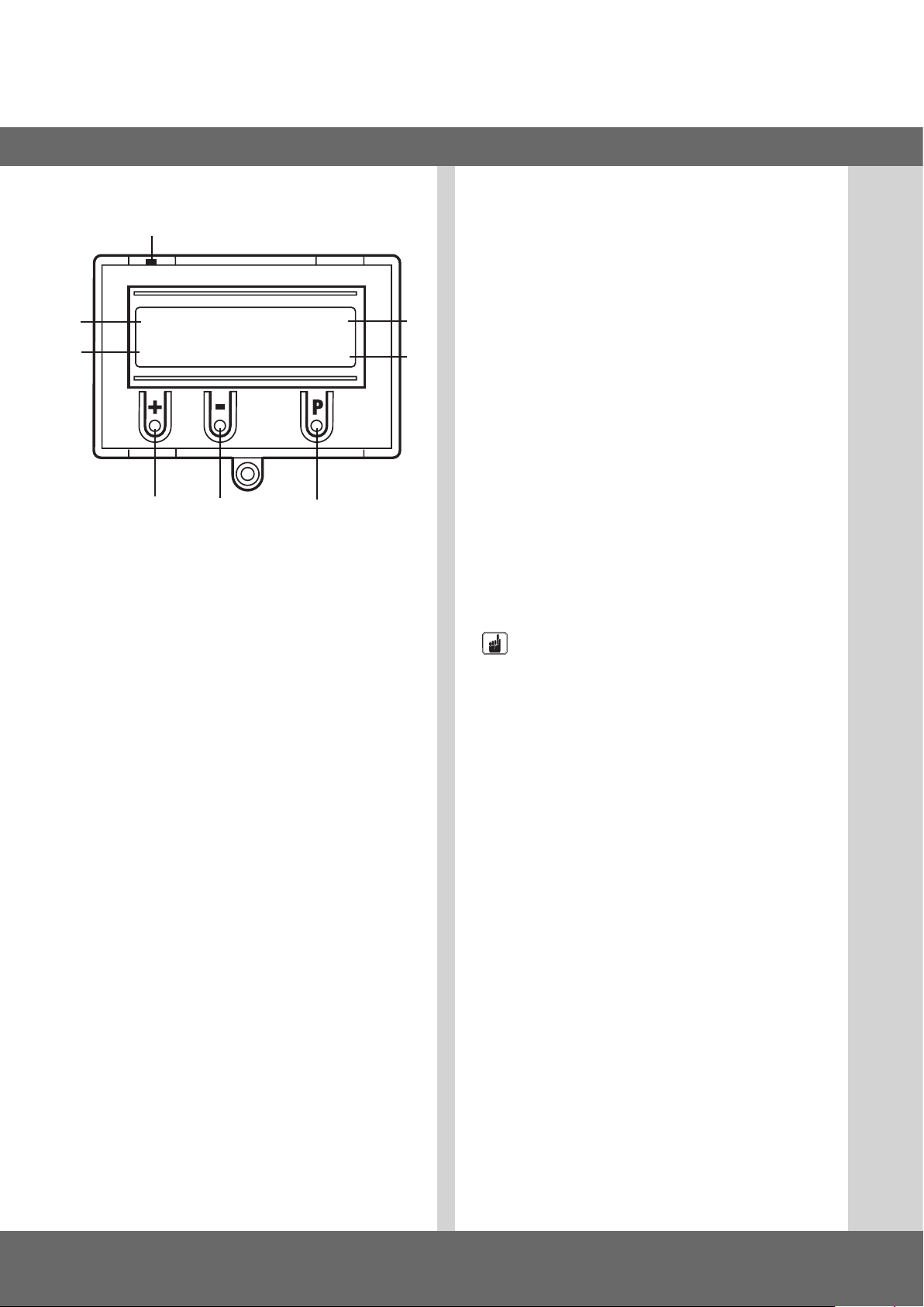
7.1 Übersicht LCD-Monitor
H
A
B
Erklärung:
A: Betriebsart / Diagnose Info
B: Parameter / Diagnose Info
C: Taste (+)
D: Taste (-)
E: Taste (P)
F: Wert / Status
G: Wert / Status
H: Jumper
AUTOMATIK O
RUHESTELLUNG
C D E
7.2 Betriebsarten des LCD-Monitors
Die Betriebsarten JUSTIERUNG, EINGABE und DIAGNOSE
werden automatisch 20 Sekunden nach dem letzten Tastendruck verlassen, die Steuerung springt in die Betriebsart
AUTOMATIK.
Betriebsart 1: AUTOMATIK
G
F
In der Betriebsart AUTOMATIK wird die Toranlage betrieben.
Display:
− Anzeige der durchgeführten Funktion
− Anzeige der möglichen Fehler
Wird im Eingabemenü der Parameter „Selbst haltung“ auf
MOD2 oder MOD3 gestellt, wechselt die Display- Anzeige von
AUTOMATIK auf HANDBETRIEB.
Betriebsart 2: JUSTIERUNG
In der Betriebsart JUSTIERUNG werden die Endlagen AUF/ZU
eingestellt.
HINWEIS
Sachschaden durch unsachgemäße Bedienung der
Steuerung!
In der Betriebsart JUSTIERUNG erfolgt keine Abschaltung
bei Erreichen der Endlage.
Durch Überfahren der Endlage kann das Tor beschädigt
werden.
Die Steuerung verfügt mit dem LCD-Monitor über vier
Betriebsarten:
1. AUTOMATIK
2. JUSTIERUNG
3. EINGABE
4. DIAGNOSE
Wenn der Jumper H gezogen wird, sind die
Tasten (+), (-) und (P) ohne Funktion.
Die Displayanzeige funktioniert weiterhin.
Nach Einschalten der Steuerung bendet sich diese im
Initialisierungsmodus. Im Display wird INIT PHASE angezeigt,
die Steuerung ist nicht betriebsbereit. Die Phase dauert ca. 5
Sekunden.
16 – Torsteuerung CS 310 / Rev.B 1.0
Eine Feineinstellung kann in der Betriebsart EINGABE
erfolgen.
Display:
− Anzeige des Endlagenwertes
Betriebsart 3: EINGABE
In der Betriebsart EINGABE können die Werte verschiedener
Parameter verändert werden.
Display:
− Anzeige des ausgewählten Parameters
− Anzeige des eingestellten Wertes / Status
Page 17

Betriebsart 4: DIAGNOSE
In der Betriebsart DIAGNOSE können torspezische Kontrollen
abgefragt werden.
Display:
− Anzeige der Kontrolle
− Anzeige des Kontrollstatus
D
Torsteuerung CS 310 / Rev.B 1.0 – 17
Page 18
8. Navigator (nur LCD-Monitor)
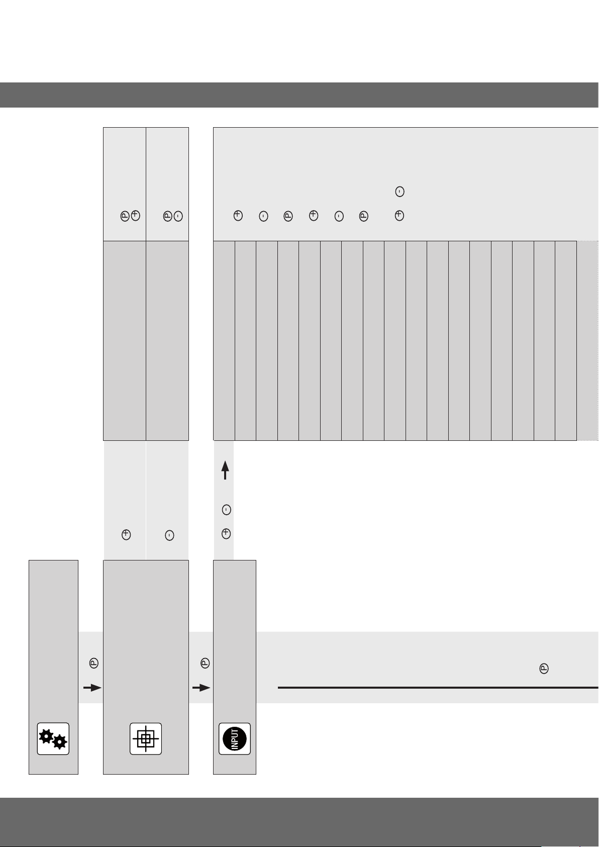
P
+
P
+
-
P
P
+
-
+
-
P
+
-
P
+
-
P
+
-
P
> 1 Sek.
> 1 Sek.
halten und
Torposition speichern:
JUSTIERUNG
Torposition speichern:
HAND AUF
halten und - > 1 Sek.
JUSTIERUNG
HAND AB
> 2 Sek
> 2 Sek.
Menü hochblättern:
Menü runterblättern:
Wert auswählen:
EINGABE
EINGABE
DEUTSCH :
FEIN-AUF : 0
EINGABE
FEIN-ZU : 0
> 1 Sek.
EINGABE
V.ES-AUF : A
Wert erhöhen:
EINGABE
V.ES-ZU : A
Wert vermindern:
EINGABE
OFFENZEIT : 0
EINGABE
Wert speichern:
Zurück zur Betriebsart
: 0
ANFAHRWARNUNG
EINGABE
VORWARNZEIT : 0
und
EINGABE:
EINGABE
AUTO ZU : MOD1
EINGABE
SCHNELL-ZU : MOD1
EINGABE
RELAIS 4 : MOD14
EINGABE
AMPELRUHE : MOD1
EINGABE
SKS : A
EINGABE
SKS FKT. : MOD1
EINGABE
SKS REV : MOD1
EINGABE
REVERS. OFF : ES ZU + 50
EINGABE
LICHTSCHRANKE / DURCHF.-LS : A
AUTOMATIK
RUHESTELLUNG
>1 Sek.
-> Position TOR AUF
JUSTIERUNG
RUHESTELLUNG
-> Position TOR ZU
>1 Sek.
> 2 Sek.
und
EINGABE
>1 Sek.
18 – Torsteuerung CS 310 / Rev.B 1.0
Page 19
+
> 2 Sek
-
P
> 2 Sek.
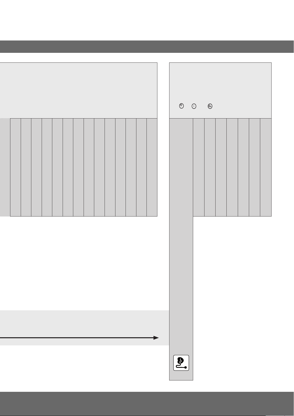
Menü hochblättern:
Menü runterblättern:
Zurück zur Betriebsart
AUTOMATIK:
D
Nur Abfrage möglich
EINGABE
LS FKT : MOD1
EINGABE
LS POINT : ES ZU
EINGABE
IMPULS : MOD1
EINGABE
EINGANG 1 : MOD1
EINGABE
EINGANG 2 : MOD1
EINGABE
SKS3 : MOD1
EINGABE
SKS4 : MOD1
EINGABE
LAUFZEIT : A
EINGABE
KRAFT : ON
EINGABE
UMKEHRZEIT : 300
EINGABE
ENDSCHALTER : A
EINGABE
SELBSTHALT. : MOD1
EINGABE
NEUSTART : OFF
EINGABE
WERKSEINSTELLUNG : OFF
DIAGNOSE
ES OBEN : ON
ES UNTEN : ON
AUF-TASTE : OFF
EINGANG 1 : OFF
ZU-TASTE : OFF
SKS 1/2/3/4 : ON
IMPULS : OFF
SCHALTUHR : OFF
DURCHF.-LS : ON
STOPKETTE : ON
STOPTASTE : ON
ZYKLUS : 4
AWG : 2599
FEHLERSPEICHER : FEHLER
Torsteuerung CS 310 / Rev.B 1.0 – 19
Page 20
9. Funktionsübersichten
9.1 Betriebsart Automatik
Anzeige Beschreibung
AUTOMATIK
LERNFAHRT
AUTOMATIK
OEFFNEN
AUTOMATIK
SCHLIESSEN
AUTOMATIK
RUHESTELLUNG
AUTOMATIK O
RUHESTELLUNG
AUTOMATIK o
RUHESTELLUNG
AUTOMATIK U
RUHESTELLUNG
AUTOMATIK u
RUHESTELLUNG
AUTOMATIK r
RUHESTELLUNG
Laufzeit wird automatisch gelernt
Das Tor fährt in die Endposition AUF
Das Tor fährt in die Endposition ZU
Das Tor steht in einer Zwischenposition
Das Tor steht in der Endposition AUF
Das Tor steht in der Position TEIL-AUF („Vor-Endlage“ oben)
Das Tor steht in der Endposition ZU
Das Tor steht in der Position TEIL-ZU („Vor-Endlage“ unten)
Das Tor steht in der Position der Reversierabschaltung
Wird im Eingabemenü der Parameter „Selbsthaltung“ auf MOD2 oder MOD3 gestellt, wechselt die Display-Anzeige von AUTOMATIK
auf HANDBETRIEB.
Anzeige Beschreibung
HANDBETRIEB
HAND AUF
HANDBETRIEB
HAND ZU
HANDBETRIEB
RUHESTELLUNG
Das Tor fährt in die Endposition AUF
Das Tor fährt in die Endposition ZU
Das Tor steht in einer Zwischenposition
20 – Torsteuerung CS 310 / Rev.B 1.0
Page 21
9.2 Betriebsart Eingabe
D
Funktion Beschreibung
DEUTSCH Wahl der Menü-Sprache DEUTSCH
FEIN-AUF Feinjustage der Endlage AUF in Bezug auf die gespeicherte Endlage AUF.
Nur sichtbar bei Systemen mit elektronischem Endschalter.
FEIN-ZU Feinjustage der Endlage ZU in Bezug auf die gespeicherte Endlage ZU.
Nur sichtbar bei Systemen mit elektronischem Endschalter.
V.ES-AUF Einstellung des Schaltpunktes Vor-Endlage AUF (TEIL-AUF) in Bezug auf die
gespeicherte Endlage ZU (Endlage ZU = AWG Wert 0).
Nur sichtbar bei Systemen mit elektronischem Endschalter.
Automatisches Einlernen der Position:
„6.5 Einstellung der elektronischen Zwischenendlagen über das LCD-Display“
V.ES-ZU Einstellung des Schaltpunktes Vor-Endschalter ZU in Bezug auf die gespeicherte
Endlage ZU.
Nur sichtbar bei Systemen mit elektronischem Endschalter.
Einstellmöglichkeiten
ENGLISH
FRANCAIS
ESPANOL
NEDERLANDS
POLSKI
CESKY
ITALIANO
-250 – 250 0
-250 – 250 0
0 = ES ZU – ES AUF, A A - lernend
A, 0 = ES ZU – ES AUF A - lernend
Werkseinstellung
DEUTSCH
Automatisches Einlernen der Position:
„6.5 Einstellung der elektronischen Zwischenendlagen über das LCD-Display“
OFFENZEIT Nach dem Öffnen fährt das Tor nach Ablauf des eingestellten Wertes automatisch in
ANFAHRWARNUNG
VORWARNZEIT
AUTO ZU MOD 1: AUTO ZU aus Endlage oben
SCHNELLZU
Richtung ZU.
Hinweis:
Durch Drücken der Taste ZU während der Offenzeit beginnt die Zufahrt sofort.
Durch Drücken der Taste AUF oder STOPP während der Offenzeit wird die Zeit neu
gestartet.
Wird eine automatische Zufahrt durch die SKS unterbrochen, so verdoppelt sich die
Offenzeit, nach 3 Versuchen, wird die automatische Schließung abgebrochen.
Vor jeder Fahrt wird die Anfahrwarnung ausgeführt. 0 – 10 Sekunden
Vor einer automatischen Zufahrt oder vor Schließen durch Impulsbetrieb wird die
Vorwarnzeit aktiviert.
Hinweis: Diese Zeit addiert sich zur Anfahrwarnung
MOD 2: AUTO ZU aus Teilauf
MOD 3: AUTO ZU aus Endlage oben und Teilauf
MOD 4: AUTO ZU aus allen Torpositionen
MOD1 : Die Offenzeit läuft normal ab
MOD2: Die Offenzeit wird abgebrochen nachdem die Lichtschranke durchfahren
wurde (Anlage schließt sofort).
MOD3: Die Offenzeit wird abgebrochen nachdem die Lichtschranke für eine
Mindestdauer (2 Sek.) unterbrochen wurde (Personenunterdrückung).
0 – 3600 Sekunden
0 = Auto-Zufahrt Aus
0 = aus
0 – 120 Sekunden 0 = Aus
MOD1
MOD2
MOD3
MOD4
MOD1
MOD2
MOD3
0 = Auto-Zufahrt Aus
0
MOD1
MOD1
Torsteuerung CS 310 / Rev.B 1.0 – 21
Page 22
Funktionsübersichten
Funktion Beschreibung
RELAIS 1 Allen 4 Relais kann ein Relaismodus von 1 - 34 zugeordnet werden.
MOD1: (Rotampel 1) Vorwarnung - Blinkend, Torlauf - Leuchtend
MOD2: (Rotampel 2) Vorwarnung - Blinkend, Torlauf - Blinkend
MOD3: (Rotampel 3) Vorwarnung - Leuchtend, Torlauf - Leuchtend
MOD4: Impulssignal bei AUF-Befehl
MOD5: Störmeldung
MOD6: Endlage AUF
RELAIS 2 MOD1 – MOD34 MOD7
RELAIS 3 MOD1 – MOD34 MOD28
RELAIS 4 MOD1 – MOD34 MOD14
MOD7: Endlage ZU
MOD8: Endlage AUF negiert
MOD9: Endlage ZU negiert
MOD10: Vor-Endlage AUF
MOD11: Vor-Endlage ZU
MOD12: Vor-Endlage ZU bis Endlage ZU
MOD13: Magnetschlossfunktion
MOD14: Bremse
MOD15: Bremse negiert
MOD16: Bremse auch in Endlage AUF eingeschaltet
MOD17: SKS betätigt oder Testfehler
MOD18: (Rotampel 4) Vorwarnung - Blinkend, Torlauf - Aus
MOD19: Vorendlage AUF bis Endlage AUF
MOD20: Aktivierung Übertragungssystem Opto
MOD21: Test der Einzugsicherung vor Auffahrt (Zusatzmodul erforderlich)
MOD22: Test der externen Sicherheitseinrichtungen vor Zufahrt
(Zusatzmodul erforderlich)
MOD23: (Grünampel) Endlage AUF - Leuchtend, Vorwarnung - AUS, Torlauf - AUS
MOD24: Kondensatorschaltung für 230V 1Ph Antriebe
MOD25: Hoichtfunktion 2 min. nach Auf-Befehl (auch indirekt durch Impuls)
MOD26: Aktivierung Übertragungssystem Funk
MOD27: Impulssignal nach Erreichen der Endlage AUF
MOD28: Relais AUS
MOD29: Tor Fährt AUF
MOD30: TOR FÄHRT ZU
MOD31: Wartung
MOD32: Akkubetrieb
MOD33: Kein Akkubetrieb
MOD34: BMA-Signal
Einstellmöglichkeiten
MOD1 – MOD34 MOD6
Werkseinstellung
AMPELRUHE
SKS MOD1: OSE
SKS FKT. MOD1: Stopp + Reversierung
SKS REV MOD1: Stopp + Reversierung zwischen EO und RP, Stopp zwischen RP und EU
REVERS.
OFF
LICHTSCHRANKE /
DURCHF.-LS
Ampeln schalten
MOD1: im Ruhezustand AUS
MOD2: im Ruhezustand EIN
MOD3: im Ruhezustand nach 5 Minuten aus
MOD2: 8K2
MOD3: DW als NC mit Testung
MOD2 Stopp + Freifahrt für 2 Sekunden
Hinweis: Sollte keine Reversierung erlaubt sein, stoppt das Tor lediglich.
MOD2 Stopp + Reversierung zwischen EO und RP, keine Aktion zwischen RP
und EU
MOD3: Stopp + Reversierung zwischen EO und EU
Hinweis: Bei Systemen mit mechanischen Endschaltern, dient der VE ZU als RP.
Punkt der Reversierabschaltung (Reverse Point RP) bevor die Endlage ZU erreicht wird.
Nur sichtbar bei Systemen mit elektronischem Endschalter.
MOD1: MFZ 2 Draht
MOD2: NC Kontakt
22 – Torsteuerung CS 310 / Rev.B 1.0
MOD1 – MOD3 MOD1
A – selbstlernend
MOD1 – MOD 3
MOD1 – MOD2 MOD1
MOD1 – MOD3 MOD1
ES ZU + 0 – 250 ES ZU + 50
A – selbstlernend
MOD1 – MOD2
A – selbstlernend
A – selbstlernend
Page 23

D
Funktion Beschreibung
LS FKT Torbewegung ZU Torbewegung AUF
MOD1: Stopp + Reversierung Keine Aktion
MOD2: Stopp und Freifahrt Keine Aktion
MOD3: STOPP Keine Aktion
MOD4: STOPP STOPP
MOD5: Stopp + Reversierung Mitfahrunterdrückung
LS POINT Zwischen dem ES ZU und dem LSPOINT wird die Lichtschranke nicht ausgewertet.
(Zargenfunktion).
Nur sichtbar bei Systemen mit elektronischem Endschalter.
IMPULS MOD1: AUF – Stopp – Zu – Stopp
MOD2: Nur AUF
MOD3: Nur AUF, Halt bei bewegtem Tor
MOD4: Nur AUF, inaktive während Bewegung
MOD5: ZU aus EO, ansonsten AUF
EINGANG 1 MOD1: Taster Teilauf
MOD2: Schalter TEILAUF
MOD3: Schalter AutoZU
MOD4: Externe UHR (Dauerauf)
MOD5: Schalter Offenhaltung / Alarm
MOD6: Schalter BMA (Notschließung) NO
MOD7: Schalter BMA (Notschließung) NC
MOD8: Schalter BMA (Notöffnung) NO
MOD9: Schalter BMA (Notöffnung) NC
MOD10: Taster Lüftung (TEILZU)
MOD11: Taster Automatische Zufahrt
Einstellmöglichkeiten
MOD1 – MOD5 MOD1
0 = ES ZU – ES AUF 0
MOD1 – MOD5 MOD1
MOD1 – MOD11 MOD1
Werkseinstellung
EINGANG 2 MOD1: NICHT aktiv
MOD2: Schlupftürschalter
8K2 Stopp bei Abweichung
MOD3: Schaltleiste AUF
8K2 Stopp und Reversierung
MOD4: Schaltleiste AUF
8K2 Stopp und Freifahrt
MOD5: Akkubetrieb
SKS3 MOD 1: nicht verwendet
MOD 2: SKS ZU
MOD 3: SKS AUF
MOD 4: Stopp
Nur in Verbindung mit dem Steckmodul drahtlose Signalübertragung in Klemme X20
zu verwenden.
SKS4 MOD 1: nicht verwendet
MOD 2: SKS ZU
MOD 3: SKS AUF
MOD 4: Stopp
Nur in Verbindung mit dem Steckmodul drahtlose Signalübertragung in Klemme X20
zu verwenden.
LAUFZEIT Überwachung der maximalen Laufzeit einer AUF- oder AB-Bewegung.
Währen der Lernfahrt wird die Laufzeit des Tors automatisch gelernt.
Bei einer Abweichung von 20% (in beide Richtungen) erscheint ein Laufzeitfehler.
Nach dem automatischen Lernen kann die Laufzeit manuell geändert werden.
MOD1 - MOD5 MOD1
MOD1 - MOD4 MOD1
MOD1 - MOD4 MOD1
A = Automatisch
1 – 300 Sekunden
A
KRAFT Automatische Kraftüberwachung ON
OFF
ON
Torsteuerung CS 310 / Rev.B 1.0 – 23
Page 24

Funktionsübersichten
Funktion Beschreibung
UMKEHRZEIT
ENDSCHALTER
SELBSTHALT.
NEUSTART Bei Aktivierung der Funktion wird die Steuerung neu gestartet. ON
WERKSEINSTELLUNGEN
Stillstandzeit bei jeder Richtungsänderung. Die Umkehrzeit bei Aktivierung der
Schaltleiste oder der Lichtschranke während der Schließbewegung beträgt ein Drittel
der eingestellten Zeit.
MOD 1: AWG
MOD 2: mechanische Endschalter
MOD1: Automatikbetrieb
MOD2: Handbetrieb für AUF + ZU mit SKS Auswertung
MOD3: Handbetrieb für ZU
MOD4: Handbetrieb für AUF
MOD5: Handbetrieb für AUF + ZU ohne SKS Auswertung
Zurücksetzen alle Parameter der Steuerung auf die Werkseinstellungen.
Erläuterungen der Relais-Modes:
A. Ampelfunktionen
Einstellmöglichkeiten
300 -
2000 Millisekunden
A – selbstlernend
MOD1 – MOD 2
MOD1 – MOD5 MOD1
OFF
Werkseinstellung
300 Millisekunden
A – selbstlernend
OFF
MOD Bezeichnung Endlage ZU Endlage AUF Vorwarnung Torlauf
MOD 1 Rotampel 1 AN / AUS * AUS Blinkend Leuchtend
MOD 2 Rotampel 2 AN / AUS * AUS Blinkend Blinkend
MOD 3 Rotampel 3 AN / AUS * AUS Leuchtend Leuchtend
MOD 18 Rotampel 4 AUS AUS Blinkend AUS
MOD 23 Grünampel AUS Leuchtend AUS AUS
* in Abhängigkeit von Parameter AMPEL RUHE
B. Positionsmeldungen
MOD Bezeichnung Bemerkungen
MOD 6 Endlage AUF Das Relais schließt den Kontakt, wenn das Tor sich in der Position Endlage AUF
bendet.
MOD 7 Endlage ZU Das Relais schließt den Kontakt, wenn das Tor sich in der Position Endlage ZU
MOD 8 Nicht Endlage AUF Das Relais schließt den Kontakt, wenn das Tor sich nicht in der Position Endlage AUF
bendet.
bendet.
24 – Torsteuerung CS 310 / Rev.B 1.0
Page 25

MOD Bezeichnung Bemerkungen
D
MOD 9 Nicht Endlage ZU Das Relais schließt den Kontakt, wenn das Tor sich nicht in der Position Endlage ZU
MOD 10 Vor-Endlage AUF / TEIL AUF Das Relais schließt den Kontakt, wenn das Tor sich in der Position Vorendlage AUF /
MOD 11 Vor-Endlage ZU Das Relais schließt den Kontakt, wenn das Tor sich in der Position Vorendlage ZU
MOD 12 Vor-Endlage ZU bis Endlage ZU Das Relais schließt den Kontakt, wenn das Tor sich in dem Bereich zwischen Endlage
MOD 19 Vor-Endlage AUF bis Endlage AUF Das Relais schließt den Kontakt, wenn das Tor sich in dem Bereich zwischen Endlage
bendet.
Teil AUF bendet.
bendet.
ZU und Vorendlage ZU bendet.
AUF und Vorendlage AUF / Teil AUF bendet.
C. Impulssignale
MOD Bezeichnung Bemerkungen
MOD 4 Impuls bei AUF-Befehl Das Relais schließt den Kontakt für 1 Sekunde, wenn das Tor einen AUF-Befehl
bekommt. Mit diesem Impuls kann beispielsweise eine Lichtansteuerung realisiert
werden.
MOD 27 Impuls nach Erreichen der Endlage AUF Das Relais schließt den Kontakt für 2 Sekunden, wenn das Tor die Position Endlage
AUF erreicht.
Mit diesem Impuls kann beispielsweise eine nachfolgende Schranke geöffnet werden.
D. Bremsfunktionen
MOD Bezeichnung Bemerkungen
MOD 14 Bremse Über das Relais wird der Schaltkontakt des Bremsgleichrichters angesteuert, um eine
MOD 15 Bremse negiert Über das Relais wird der Schaltkontakt des Bremsgleichrichters angesteuert, um eine
MOD 16 Bremse bleibt in Offenzeit ON Über das Relais wird der Schaltkontakt des Bremsgleichrichters angesteuert, um eine
schnellere Bremsfunktion zu realisieren. Der Kontakt wird geschlossen und somit die
Bremse wird gelüftet, sobald sich das Tor bewegt (Ruhestrombremse).
schnellere Bremsfunktion zu realisieren. Der Kontakt wird geöffnet und somit die
Bremse wird gelüftet, sobald sich das Tor bewegt (Arbeitsstrombremse).
schnellere Bremsfunktion zu realisieren. Der Kontakt wird geschlossen und somit
die Bremse wird gelüftet, sobald sich das Tor bewegt (Ruhestrombremse). Um in
der oberen Endlage ein sanfteres Stoppverhalten des Tores zu erreichen, wird der
Schaltkontakt in der Position Endlage AUF (OFFENZEIT) nicht geschaltet.
Torsteuerung CS 310 / Rev.B 1.0 – 25
Page 26

Funktionsübersichten
E. Störmeldungen
MOD Bezeichnung Bemerkungen
MOD 5 Störmeldung Das Relais schließt den Kontakt, wenn ein Stoppbefehl oder einen Fehler vorliegt.
MOD 17 SKS betätigt Das Relais öffnet den Kontakt, wenn die Schaltleiste betätigt wird. Ein Fehler der
Alle Fehler des Kapitals 10 führen zur Betätigung des Relais.
Schaltleiste oder ein fehlgeschlagener Test wird über MOD 5 angezeigt.
F. Funktionen für externes Zubehör
MOD Bezeichnung Bemerkungen
MOD 13 Magnetschlossfunktion Das Relais schließt vor jeder Torbewegung. In Ruhestellung ist das Relais geöffnet.
MOD 20 Aktivierung Übertragungssystem Opto Vor jedem AB-Befehl wird das Übertragungssystem Opto aktiviert und bleibt für die
MOD 21 Test der Einzugssicherung Das Relais erzeugt ein Testsignal beim Erreichen der Endlage ZU und erwartet als
MOD 22 Test der externen Sicherheitseinrichtungen Das Relais erzeugt ein Testsignal beim Erreichen der Endlage AUF und erwartet als
MOD 24 Kondensatorschaltung Bei jedem Fahrbefehl wird das Relais für ca. 1 Sekunde geschlossen. Mit Hilfe dieses
Es ist eine Verzögerungszeit von 0,5 Sekunden vor jeder Torbewegung eingestellt.
Dauer der Zufahrt aktiv.
Durch diese Aktivierung erfolgt eine um ca. 0,5 Sekunde verzögerte Abfahrt.
Reaktion auf das Testsignal eine Betätigung des Stopp-Kreises.
Reaktion auf das Testsignal eine Betätigung des Schaltleisteneingangs.
Relais wird ein für Wechselstromanwendungen benötigter zusätzlicher Startkondensator hinzugeschaltet, um ein sicheres Anlaufen des Motors zu gewährleisten.
MOD 25 Hoichtfunktion Bei jedem AUF-Befehl wird das Relais für 2Minuten geschlossen und kann somit zur
MOD 26 Aktivierung Übertragungssystem FUNK Vor jedem AB-Befehl wird das Übertragungssystem Funk mit einem Impuls aktiviert.
MOD 28 Relais AUS Das Relais ist immer geöffnet.
Ansteuerung einer Beleuchtung verwendet werden.
Die Dauer der Aktivierung muss an dem Übertragungssystem eingestellt werden.
Durch diese Aktivierung erfolgt eine um ca. 0,5 Sekunde verzögerte Abfahrt.
26 – Torsteuerung CS 310 / Rev.B 1.0
Page 27
9.3 Betriebsart Diagnose / Fehlerspeicher
Anzeige Bedeutung Zustand
D
ES-AUF Endlage AUF OFF: betätigt
ES-ZU Endlage ZU OFF: betätigt
AUF-TASTE AUF-Taste ON: betätigt
EINGANG 1 EINGANG 1 (X4 / 9 + 10) ON: betätigt
ZU-TASTE ZU-Taste ON: betätigt
SKS 1/2/3/4 Schließkantensicherung
SKS 2 = Eingang 2
IMPULS Impuls-Taster ON: betätigt
ON: nicht betätigt
ON: nicht betätigt
OFF: nicht betätigt
OFF: nicht betätigt
OFF: nicht betätigt
ON: System ist geschlossen
OFF: System ist unterbrochen (Störung)
OFF: nicht betätigt
SCHALTUHR Wochenzeitschaltuhr ON: betätigt
DURCHF.-LS Durchfahrtlichtschranke ON: geschlossen
STOPPKETTE - NOT-AUS der Steuerung
- Stopp-Systeme des Antriebs
STOPPTASTE - Stopp-Taste der Steuerung ON: geschlossen
ZYKLUS Torzyklen-Zähler Anzeige der Torzyklen
AWG Absolutwertgeber Anzeige des Torpositionswertes
FEHLERSPEICHER Wechsel der Anzeige im
2-Sekunden-Takt
OFF: nicht betätigt
OFF: unterbrochen (Störung)
ON: geschlossen
OFF: unterbrochen (Störung)
OFF: unterbrochen (Störung)
FEHLER
ANZAHL
ZYKLUS
Torsteuerung CS 310 / Rev.B 1.0 – 27
Page 28
10. Fehleranzeige und Behebung
10.1 Fehleranzeige am LCD-Display
Störung / Fehlermeldung Ursache Behebung
Anlage reagiert nicht - Keine Spannung vorhanden - Spannungsversorgung von Antrieb und
Tor fährt bei Betätigung der AUF-Taste in die
Endlage ZU
Tor fährt bei Betätigung der ZU-Taste in die
Endlage AUF
FAULT – X - interner Software- oder Hardware-Fehler - Steuerung neu starten
STOPKETTE - Der Stopp-Kreis ist unterbrochen.
ERROR LAUFZEIT - Die programmierte Laufzeit ist überschritten
- Drehfeld liegt falsch an
X3 1,2:
Not-Aus, Schlaffseilschalter, Schlupftürkontakt, Einzugsicherung
X6 1,2:
Interner Ein-Aus Schalter
X11 4,8:
Sicherheitskreis Antrieb
X2 B1/B2:
Brücke
X3 3,4:
externer Stopp-Taster
X7 1,2:
interner Stopp-Taster
worden
Steuerung überprüfen
- Drehfeld überprüfen und ggf. Rechts-Drehfeld
herstellen
- Stopp-Kreis prüfen und schließen
- Laufweg des Tores überprüfen
- Laufzeit neu programmieren
ERROR AWG - Kommunikationsfehler zwischen Endschalter
und Steuerung
ERROR ENDLAGE - Das Tor steht außerhalb der Endlagen
- Die Endlagen sind noch nicht programmiert
ERROR KRAFT - Die Kraftüberwachung hat angesprochen - Torgängigkeit überprüfen
ERROR DREHFELD - An der Klemme X1 liegt ein falsches Drehfeld
an
ERROR SKS ZU - Schließkantensicherung fehlerhaft - Schließkantensicherung und Spiralkabel
- Schließkantensicherung hat angesprochen - Hindernis aus Torweg entfernen
ERROR SKS ZU 2 - Schließkantensicherung fehlerhaft - Schließkantensicherung und Spiralkabel
- Schließkantensicherung hat angesprochen - Hindernis aus Torweg entfernen
ERROR SKS AUF 2 - Schließkantensicherung fehlerhaft
- Schließkantensicherung hat angesprochen - Hindernis aus Torweg entfernen
- Kabel- und Steckverbindung überprüfen
- Programmierung der Endlagen überprüfen
und ggf. neu einstellen
- Kraftwert neu einstellen
- Sicherstellen, dass ein rechtes Drehfeld
anliegt
überprüfen
überprüfen
- Schließkantensicherung und Spiralkabel
überprüfen
28 – Torsteuerung CS 310 / Rev.B 1.0
Page 29

Störung / Fehlermeldung Ursache Behebung
D
ERROR SKS ZU 3 - Schließkantensicherung fehlerhaft - Schließkantensicherung und Spiralkabel
- Schließkantensicherung hat angesprochen - Hindernis aus Torweg entfernen
ERROR SKS AUF 3 - Schließkantensicherung fehlerhaft
- Schließkantensicherung hat angesprochen - Hindernis aus Torweg entfernen
ERROR SKS ZU 4 - Schließkantensicherung fehlerhaft - Schließkantensicherung und Spiralkabel
- Schließkantensicherung hat angesprochen - Hindernis aus Torweg entfernen
ERROR SKS AUF 4 - Schließkantensicherung fehlerhaft
- Schließkantensicherung hat angesprochen - Hindernis aus Torweg entfernen
ERROR SKS-TESTUNG
ERROR LICHTS. - Die Lichtschranke hat angesprochen
- Der DW-Schalter löst in der Endlage ZU nicht
aus
überprüfen
- Schließkantensicherung und Spiralkabel
überprüfen
überprüfen
- Schließkantensicherung und Spiralkabel
überprüfen
- DW-Schalter, Spiralkabel und Prol
überprüfen
- Einstellung der Endlage ZU überprüfen
- Ausrichtung der Lichtschranke und Lichtweg
überprüfen
ERROR LS-TEST - Die Testung der Lichtschranke hat
ERROR EINZUG
fehlgeschlagen
- Der Test der Einzugsicherung
(RELAIS MODUS21) hat fehlgeschlagen
- Ausrichtung der Lichtschranke und Lichtweg
überprüfen
- Verkabelung überprüfen
- Ausrichtung der Lichtschranke und Lichtweg
überprüfen
- Verkabelung überprüfen
Nach Behebung der Störungsursache muss die Steuerung einmal spannungsfrei geschaltet werden!
Torsteuerung CS 310 / Rev.B 1.0 – 29
Page 30

Fehleranzeige und Behebung
10.2 Fehleranzeige über LED
LED H4 (Grün, Steckkarte oder CSI-Taster)
Fehler Anzeige LED H4 – Grün Bemerkungen
Betriebsspannung fehlt Aus Keine Versorgungsspannung vorhanden
LED H6 (Rot)
Fehleranzeige LCD-Display Anzeige LED H6 – Rot Bemerkungen
STOPP 1x Blinken STOPP-Kette muss geschlossen sein, dann Fahrt
ERROR AWG 2x Blinken Stopp der Anlage, Fehler im Übertragungs-
ERROR ENDLAGE 3x Blinken Stopp der Anlage und keine Fahrt möglich,
ERROR DREHFELD 4x Blinken Stopp der Anlage und keine Fahrt möglich,
ERROR KRAFT 5x Blinken Stopp der Anlage, Fehler mit Stopp quittieren,
ERROR LAUFZEIT 6x Blinken Stopp der Anlage, Fehler mit Stopp quittieren,
ERROR SKS / LICHTSCHRANKE An Fahrt nur in Totmann ZU möglich, Schaltleiste
möglich
protokoll, Fehler mit Stopp quittieren, erneuter
Anlauf mit Tastendruck möglich
Steuerung spannungsfrei schalten, Justierung
der Endlagen neu durchführen
Drehfeld tauschen, Steuerung spannungsfrei
schalten
erneuter Anlauf mit Tastendruck möglich
erneuter Anlauf mit Tastendruck möglich
überprüfen
30 – Torsteuerung CS 310 / Rev.B 1.0
Page 31

11. Technische Daten
D
Abmessungen
Gehäuse:
Montage: senkrecht an der Wand; Mindesthöhe von
Versorgung über
L1, L2, L3, N, PE:
Absicherung: 10 A K-Charakteristik
Eigenverbrauch der
Steuerung:
Steuerspannung: 24 V DC, max. 500 mA; abgesichert durch
Steuereingänge: 24 V DC, alle Eingänge sind potentialfrei anzu-
Steuerausgänge: 24 V DC, max. 500 mA
RS485 A und B nur für elektronische Endschalter
215 x 275 x 190 mm
1.100mm
400 V, 50 / 60Hz; Aufnahmeleistung max.
2200W - 3,2 A; Einschaltdauer 60% bei einer
Laufzeit von max. 120 s
max. 750 mA
selbstrückstellende Sicherung für externe
Sensorik
schließen. min. Signaldauer für Eingangssteuerbefehl >100 ms
RS485 Pegel, abgeschlossen mit 120 Ω
Vibrationen: schwingungsarme Montage, z.B. an einer
gemauerten Wand
Schutzart IP 65
Gewicht ca. 1,8 kg
Sicherheitskette /
Notaus:
Eingang Sicherheitsleiste (Schutzniveau C):
Lichtschranke
(Schutzniveau D):
Display (LCD): Als Programmierplatine LCD darf nur ein
Relaisausgänge: werden induktive Lasten geschaltet (z.B. weitere
alle Eingänge unbedingt potentialfrei anschließen; bei Unterbrechung der Sicherheitskette ist
keine elektrische Bewegung des Antriebes mehr
möglich, auch nicht in Totmannschaltung
Performance Level C
für elektrische Sicherheitsleisten mit
8,2 kΩ Abschlusswiderstand und für
dynamische optische Systeme
Falls die Lichtschranke als Schutzsystem
nach Niveau D verwendet wird, muss deren
Funktion regelmäßig, mindestens innerhalb von
6 Monaten geprüft werden.
MFZ Zweidrahtlichtschranken sind selbsttestend, hier entfällt diese Anforderung.
Originaldisplay der Firma MFZ zum Einsatz
kommen.
Relais oder Bremsen), so müssen diese mit entsprechenden Entströmmaßnahmen (Freilaufdiode, Varistoren, RC-Glieder) ausgerüstet werden.
Arbeitskontakt potentialfrei; min. 10 mA ;
max. 230 V AC / 4A.
Einmal für Leistungsschaltung benutzte
Kontakte können keine Kleinströme mehr
schalten.
Temperatur bereich: Betrieb: -10°C ... +45°C
Lagerung: -25°C ... +70°C
Luftfeuchte: bis 80% nicht kondensierend
Torsteuerung CS 310 / Rev.B 1.0 – 31
Page 32

12. Wartung
Die Steuerung CS 310 ist wartungsfrei.
GEFAHR!
Lebensgefahr durch Stromschlag!
Vor Wartungsarbeiten an der Steuerung oder der
Toranlage trennen Sie die Steuerung unbedingt von der
Stromversorgung. Stellen Sie sicher, dass während der
Arbeiten die Stromversorgung unterbrochen bleibt.
Bei der Wartung der Toranlage müssen folgende Punkte
beachtet werden:
− Die Wartung der Toranlage darf nur von autorisierten
Personen durchgeführt werden.
− Die Richtlinie ASR A1.7 muss eingehalten werden.
− Verschlissene oder defekte Teile müssen ausgetauscht
werden.
− Es dürfen nur zugelassene Teile montiert werden.
− Die Wartung muss dokumentiert werden.
− Ausgetauschte defekte Teile müssen fachgerecht entsorgt
werden.
32 – Torsteuerung CS 310 / Rev.B 1.0
Page 33

13. EG-Einbauerklärung
D
Hiermit erklären wir, dass das nachfolgend bezeichnete
Produkt
Torsteuerung CS 310
den grundlegenden Anforderungen der Maschinenrichtlinien
(2006/42/EG) entspricht:
Die unvollständige Maschine entspricht weiterhin allen
Bestimmungen der EG -Bauprodukten-Richtlinie (89/106/
EWG), der EG -Elektromagnetische Verträglichkeit Richtlinie (2004/108/EG) und der EG -Niederspannung Richtlinie
(2006/95/EG).
Folgende Normen wurden angewandt:
EN 60204-1
Sicherheit von Maschinen, elektrische Ausrüstung von
Maschinen; Teil 1: Allgemeine Anforderungen
EN ISO 12100
Sicherheit von Maschinen – Allgemeine Gestaltungsleitsätze Risikobeurteilung und Risikominderung
Die speziellen technischen Unterlagen wurden gemäß
AnhangVII Teil B der EG-Maschinenrichtlinie 2006/42/EG
erstellt. Wir verpichten uns, diese den Marktüberwachungs-
behörden auf begründetes Verlangen innerhalb einer angemessenen Zeit in elektronischer Form zu übermitteln.
Für die Zusammenstellung der technischen Unterlagen ist
bevollmächtigt:
Marantec GmbH & Co. KG, Remser Brook 11,
D-33428 Marienfeld
Die unvollständige Maschine darf erst dann in Betrieb genommen werden, wenn festgestellt wurde, dass die Maschine,
in die die unvollständige Maschine eingebaut werden soll,
den Bestimmungen der Richtlinie Maschinen (2006/42/EG)
entspricht.
Ort, Datum
Marienfeld, den 02.01.2013
Herstellerunterschrift
DIN EN 12453
Nutzungssicherheit kraftbetätigter Tore – Anforderungen
DIN EN 61000-6-2
Elektromagnetische Verträglichkeit (EMV) - Teil 6-2:
Fachgrundnormen – Störfestigkeit für Industriebereiche
DIN EN 61000-6-3
Elektromagnetische Verträglichkeit (EMV) - Teil 6-3:
Fachgrundnormen – Störaussendung für Wohnbereich,
Geschäfts- und Gewerbebereiche sowie Kleinbetriebe
DIN EN 60335-1
Sicherheit elektrischer Geräte für den Hausgebrauch und
ähnliche Zwecke - Teil 1: Allgemeine Anforderungen
DIN EN 60335-2-103
Sicherheit elektrischer Geräte für den Hausgebrauch und
ähnliche Zwecke - Teil 2-103: Besondere Anforderungen für
Antriebe für Tore, Türen und Fenster
Klaus Goldstein
Funktion des Unterzeichners
Geschäftsleitung
Torsteuerung CS 310 / Rev.B 1.0 – 33
Page 34
14. Anhang
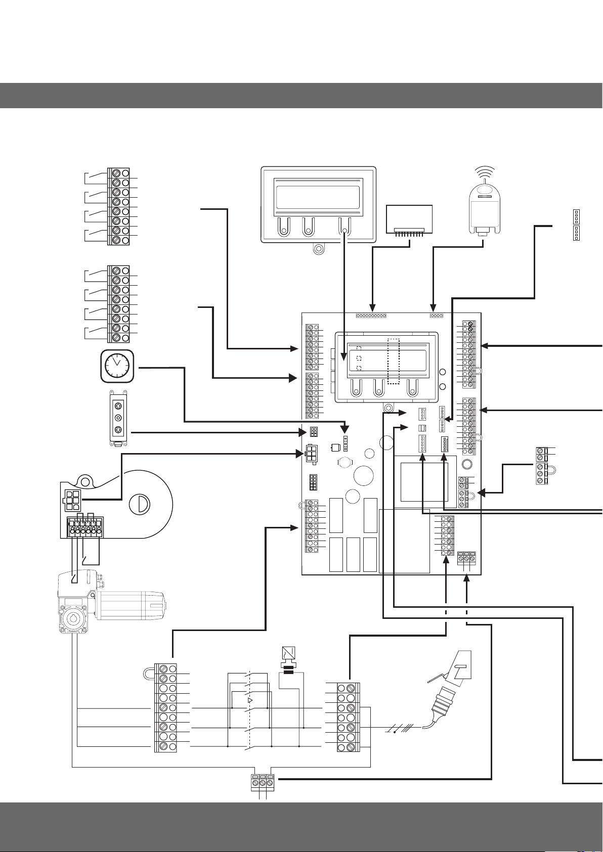
14.1 Übersicht der Anschlüsse
Klemmleiste X5
(potentialfreie Schaltkontakte)
1
- Relais 1
2
3
- Relais 2
4
5
- Relais 3
6
7
- Relais 4
8
Klemmleiste X15
(mechanische Endschalter)
1
- Endschalter AUF
2
3
- Endschalter ZU
4
5
- Vorendschalter AUF
6
7
- Vorendschalter ZU
8
X10
X11
X8
MSBUS
X17
X16
X5
1
2
3
4
5
6
7
8
1
2
3
4
5
6
7
X15
8
X14
X11
X18
B1
B2
W
V
U
X2
X10
X20
S1
S2
X8
S3
X12
X6
X9
X17
X16
X7
X13
N
L3
L2
L1
X4
12
11
10
9
8
7
6
5
4
3
H4
2
1
X3
H6
10
9
8
7
6
5
4
3
2
1
X19
X1
L
N
PEPEPE
F1
Klemmleiste X19
(Versorgung externer
Geräte)
L
N
X2
B2
B1
W
V
U
34 – Torsteuerung CS 310 / Rev.B 1.0
K2
13 5135
K1
24 6246
PEPEPE
T1
X1
N
L3
400V/50Hz/3/N/PE
L2
L1
Page 35
D
X4
X3
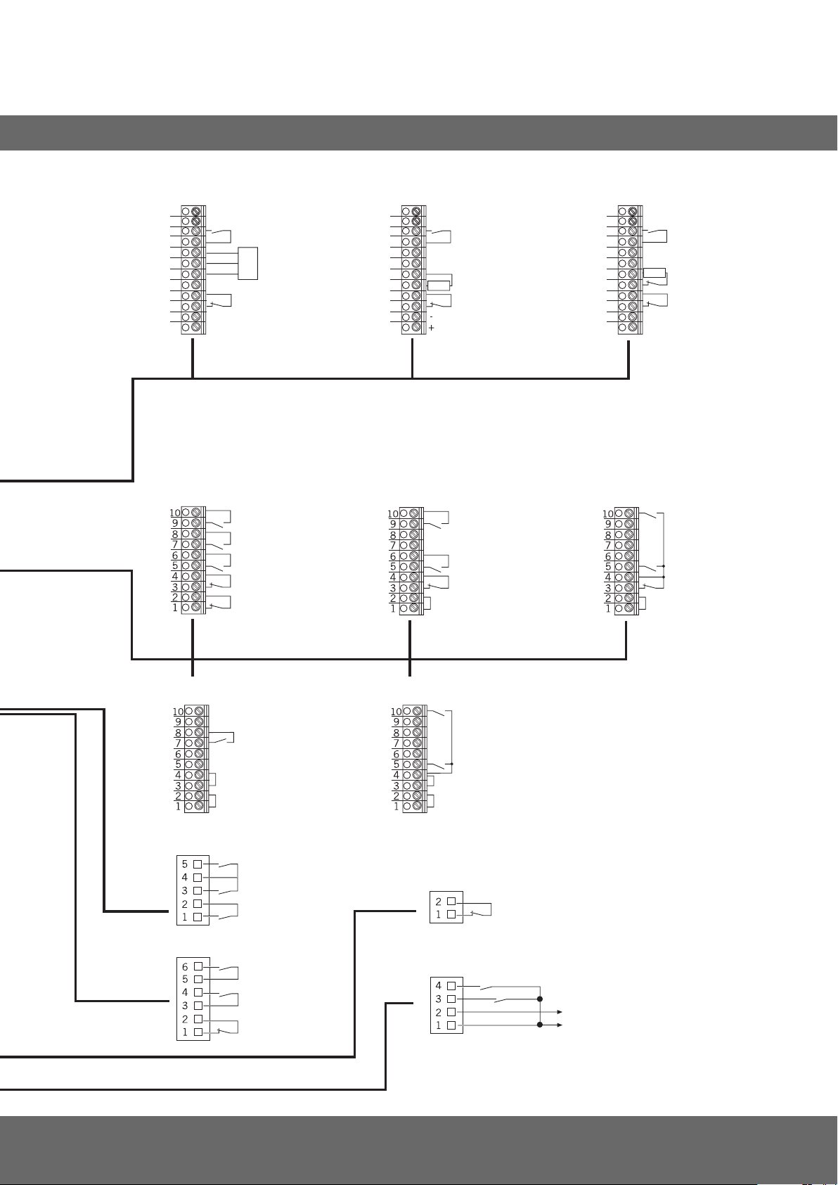
Klemmleiste X4
(für opto-elektronische Schließkantensicherung)
12
11
10
9
8
7
6
5
4
3
-
2
+
1
Klemmleiste X3
(Belegung)
0V
Sig
+ 12 V
- Taster ZU
- Taster Impuls1
2
- TEIL-AUF
- Schließkanten sicherung
OPTO
- Durchfahrt Lichtschranke
- 24 V DC / 250 mA
- Taster AUF
- Taster STOPP
- Not Aus,
Schlaffseilschalter,
Schlupftürkontakt,
Einzug sicherung
Klemmleiste X4
( für 8,2 kOhm-Schließkantensicherung)
12
11
10
9
8
7
6
8,2 KOhm
5
3
4
4
3
2
1
Taster AUF / STOPP / ZU
(6-Ader Lösung)
- Taster ZU
2
- TEIL-AUF
- Schließkanten sicherung
- Durchfahrt
Lichtschranke
- 24 V DC / 250 mA
3
4
- Taster AUF
- Taster STOPP
Klemmleiste X4
(für pneumatische Schließkantensicherung - DW)
12
11
10
9
8
7
8,2 KOhm
6
5
4
3
-
2
+
1
Taster AUF / STOPP / ZU
(4-Ader Lösung)
- Taster ZU
2
- TEIL-AUF
- Schließkanten sicherung
- Durchfahrt
Lichtschranke
- 24 V DC / 250 mA
3
4
- Taster AUF
- Taster STOPP
5
Impulstaster
(Folgesteuerung)
Deckeltaster CS
X13
Deckeltaster KDT
X7
Schlüsselschalter AUF / ZU
- Taster IMPULS
- ZU
- AUF
- Taster ZU
- Taster AUF
Interner EIN/AUS-Schalter
X6
- Taster HALT
- Taster ZU
- Taster AUF
- Taster STOPP
X12
Externer Funk
- Taster IMPULS
- Taster AUF
- GND
- 24 V DC
1
Folgesteuerung
2
Taster oder Umschalter
3
wirkt in Abwärtsrichtung
4
für externe Schaltgeräte
(Anschluss an Klemme 1 und 2)
5
- Ein 8,2 KOhm-Widerstand muss in
Reihe geschaltet werden
- Der Eingabepunkt SKS-TEST muss
eingeschaltet werden
wt: weiß
gr: grün
br: braun
Torsteuerung CS 310 / Rev.B 1.0 – 35
Page 36

#1700016725
#105030
Page 37

Operating Instructions for Control CS 310
GB
CS 310 Gate Controls / Rev.B 1.0 – 1
Page 38
1. Contents
2. Information in this document
1. Contents 2
2. Information in this document 2
3. General safety instructions 3
4. Overview of product 4
5. Initial operation 6
6. Setting the end positions 13
7. Programming with the LCD monitor 16
8. Navigator (LCD monitor only) 18
9. Overview of functions 20
10. Errormessagesandrectication 28
11. Technical data 31
12. Maintenance 32
13. EC Declaration of Incorporation 33
14. Appendix 34
Original operating instructions
− Copyright.
− No part of these instructions may be reproduced without
our prior approval.
− Subject to alterations in the interest of technical progress.
− All dimensions given in mm.
− The diagrams in this manual are not to scale.
Key to symbols
DANGER!
Indicates a hazard with a high level of risk which, if not
avoided, will result in death or serious injury.
WARNING!
Indicates a hazard with a medium level of risk which, if not
avoided, could result in death or serious injury.
CAUTION!
Indicates a hazard with a low level of risk which, if not
avoided, could result in minor or moderate injury.
NOTICE
Indicates an imminent danger of damage or destruction.
CHECK
Indicates a check to be performed.
REFERENCE
Reference to separate documents which must be complied
with.
Action request
− List, itemisation
Reference to other sections of this document
2 – CS 310 Gate Controls / Rev.B 1.0
Page 39

3. General safety instructions
GB
DANGER!
Failure to comply with the documentation could
result in life-threatening danger!
Be sure to follow all the safety instructions in this
document.
Warranty
The function and safety of the equipment is only guaranteed
if the warning and safety instructions included in these
operating instructions are adhered to.
Marantec GmbH + Co.KG is not liable for personal injury or
damage to property if these occur as a result of the warnings
and safety advice being disregarded.
Marantec does not accept any liability or warranty for damage
due to the use of non-approved spare parts and accessories.
Using the equipment for its intended purpose
The CS 310 controls are designed only for controlling gates
and doors with digital or mechanical end position systems.
Target group
Onlyqualiedandtrainedelectriciansmayconnect,
programme and service the controls.
Qualiedandtrainedelectriciansmustmeetthefollowing
requirements:
− knowledgeofthegeneralandspecicsafetyandaccident-
prevention regulations.
− knowledge of the relevant electrical regulations,
− training in the use and care of appropriate safety
equipment.
− capable of recognising the dangers associated with
electricity.
Instructions regarding installation and connection
− The control must be disconnected from the electricity
supply before carrying out any electrical work. It must be
ensured that the electricity supply remains disconnected for
the duration of the works.
− Local protective regulations must be complied with.
Information concerning operation
− Children should not be allowed to play with permanently
mounted adjusting or control devices.
− Keep remote controls beyond the reach of children.
Regulations and bases for testing
For connecting, programming and servicing, the following
regulations must be observed (the list is not exhaustive).
Construction product standards
− EN13241-1(Productswithoutreresistanceorsmoke
control characteristics)
− EN 12445 (Safety in use of power operated doors -
Test methods)
− EN 12453 (Safety in use of power operated doors -
Requirements)
− EN 12978 (Safety devices for power operated doors and
gates - Requirements and test methods)
EMC
− EN 55014-1 (Radio disturbance, household appliances)
− EN 61000-3-2 (Disturbances in supply systems -
harmonic currents)
− EN 61000-3-3 (Disturbances in supply systems -
voltageuctuations)
− DIN EN 61000-6-2 (Electromagnetic compatibility (EMC) -
Part 6-2: Generic standards – Immunity for industrial
environments)
− DIN EN 61000-6-3 (Electromagnetic compatibility (EMC) -
Part 6-3: Generic standards – Emission standard for
residential, commercial and light-industrial environments)
Machinery Directive
− EN 60204-1 (Safety of machinery, electrical equipment of
machines) Part 1: General requirements
− EN ISO 12100 (Safety of machinery – general principles for
design - risk assessment and risk reduction)
CS 310 Gate Controls / Rev.B 1.0 – 3
Page 40

General safety instructions
4. Overview of product
Low voltage
− DIN EN 60335-1 (Household and similar electrical
appliances - Safety - Part 1: general requirements)
− DIN EN 60335-2-103 (Household and similar electrical
appliances - Safety - Part 2-103: Particular requirements for
drives for gates, doors and windows)
Committee for Workplaces (ASTA)
− Workplace regulation ASR A1.7 (“Doors and gates“)
4.1 Various options
The following package options are available for the CS 310
control:
− CS 310 control with LCD monitor
− CS 310 control with LCD monitor in housing
− CS 310 control with LCD graphic monitor
− CS 310 control with LCD graphic monitor in housing
− CS 310 control without LCD monitor (monitor is required
for all settings except the end position setting)
Alltheaboveoptionscanbettedwithaplug-inweekly
timer, a plug-in radio receiver and a plug-in transmission
system (for optosensors).
The following options are available for the housing.
− Housing with CS three-button input unit
− Housing with KDT three-button input unit
− Housing with ON/OFF key switch
− Housing with main switch
− Housing with emergency OFF switch
The operating instructions describe the connection
possibilities and programming procedures for the different
models:
− CS 310 control with attached LCD display board
4 – CS 310 Gate Controls / Rev.B 1.0
Page 41
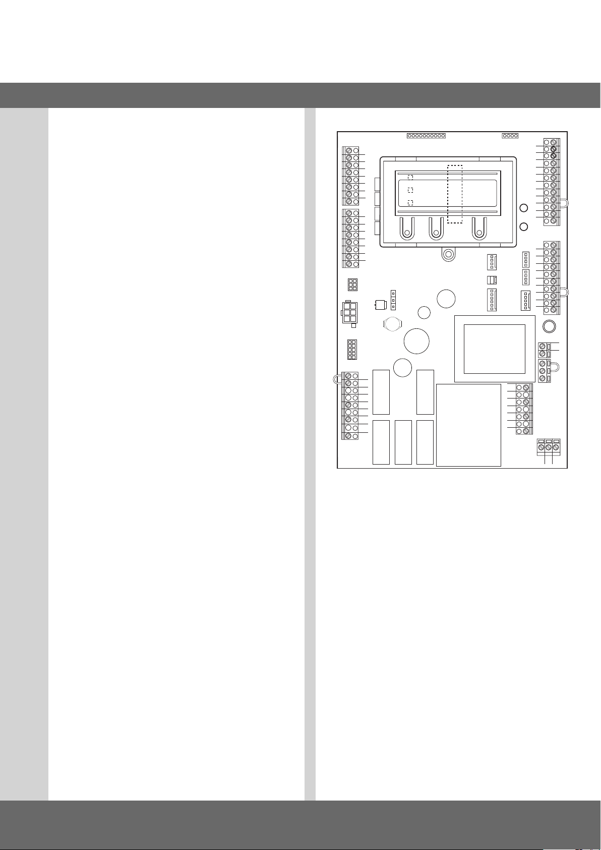
4.2 CS 310 basic board
(with attached LCD display monitor)
Key:
X1: Terminal block for mains connection
X2: Terminal block for motor
X3: Terminal block for command devices
X4: Terminal block for safety elements
X5: Terminal block for relay
X6: Sockets for internal ON-OFF switch
X7: Sockets for internal 3-button input unit
X8: Socket for monitor (under monitor)
X9: Sockets for radio receiver
X10: Sockets for weekly timer
X11: Sockets for digital end position system
X12: Socket for external radio receiver
X13: Sockets for CS three-button input unit
X14: Interface RS 485
- Connection for CSI 3-button input unit
- Connection for RS 485 display
X15: Connection for mechanical end position system
X16: Connection for BUS system (MS BUS)
X17: Connection for BUS system (MS BUS)
X18: Frequency converter interface
X19: Power supply for external devices
230V / 50 Hz protected by F1 (1 A delay) fuse
X20: Sockets for transmission system
H4: Operational readiness illuminated when control is
working
H6: status message lights up when the safety devices are
activated or in the case of errors
S1: Programming button (+) (under monitor)
S2: Programming button (-) (under monitor)
S3: Programming button (P) (under monitor)
X5
X2
1
2
3
4
5
6
7
8
1
2
3
4
5
6
7
8
X14
X11
X18
B1
B2
W
V
U
X15
X10
S1
S2
S3
X20
X8
X12
X6
X7
X9
X17
X16
X13
N
L3
L2
L1
H4
H6
X4
12
11
10
10
X1
9
8
7
6
5
4
3
2
1
9
8
7
6
5
4
3
2
1
X19
GB
X3
F1
L
N
PEPEPE
CS 310 Gate Controls / Rev.B 1.0 – 5
Page 42
5. Initial operation
5.1 General
To guarantee that the equipment functions properly, it must
be ensured that:
− The door/gate is installed and operational.
− The operator motor is installed and ready for operation.
− The command and safety devices are installed and ready for
operation.
− The control housing with the CS 310 control is installed.
REFERENCE
The relevant manufacturers’ instructions must be adhered to
for the installation of the door/gate, the operator motor, and
the command and safety devices.
5.2 Mains connection
Preconditions
To guarantee that the controls function properly, the following
points must be ensured:
− The mains voltage must correspond to the voltage stated
on the type plate.
− The mains voltage must be the same as the voltage of the
operator.
− Forathree-phasecurrent,aclockwiserotatingeldis
required.
− For a permanent connection, an all-pole main switch must
be used.
− For a three-phase connection, only 3-way automatic circuit
breakers (10 A) may be used.
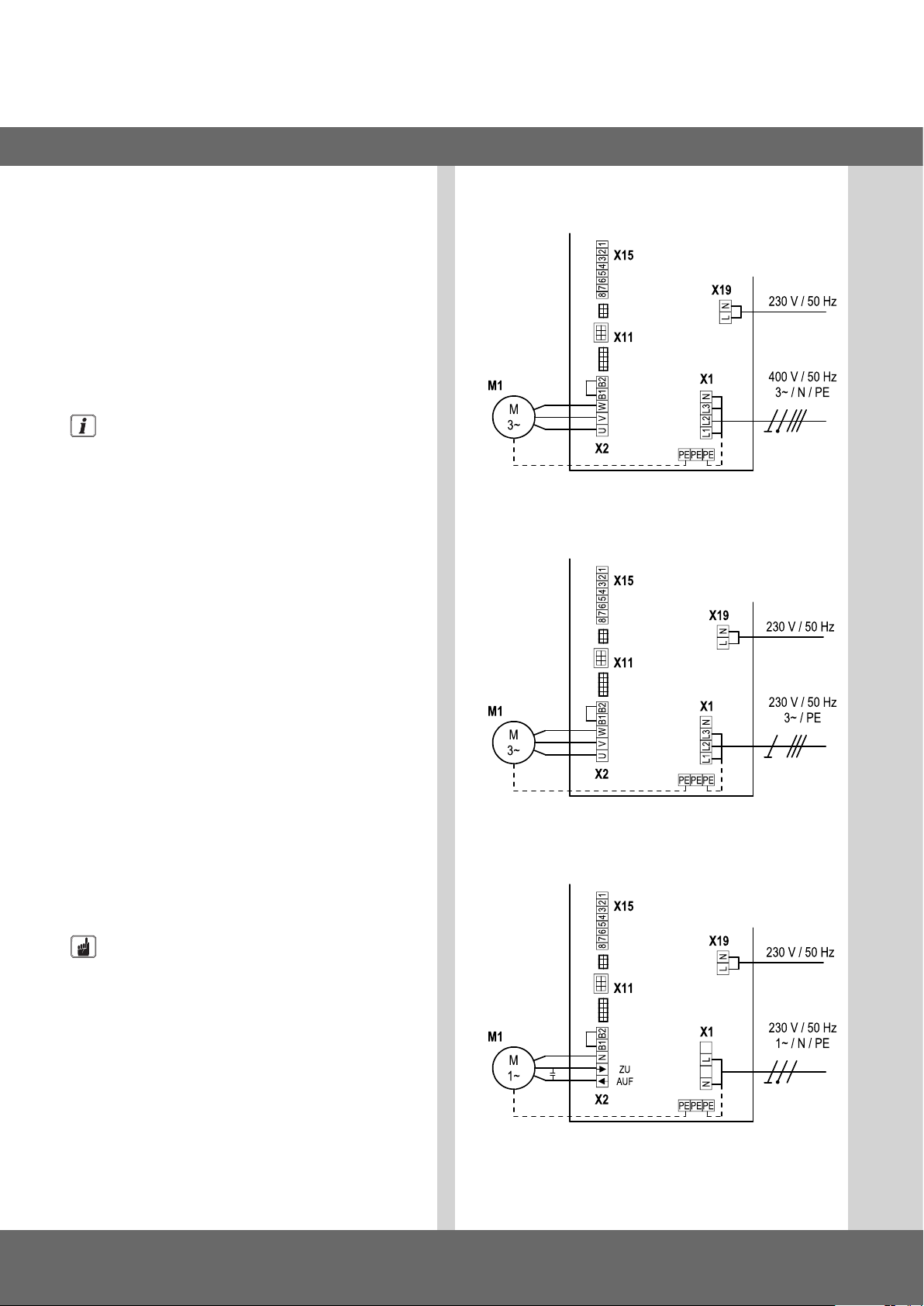
Detailed circuit diagram for mains connection and
motor (400 V / three phase)
Detailed circuit diagram for mains connection and
motor (230 V / three phase)
Detailed circuit diagram for mains connection and
motor (230 V / single phase)
NOTICE
Malfunctions can occur as a result of incorrect
installation of the control!
Beforeswitchingonthecontrolforthersttime,acheck
must be carried out after completing the wiring to ensure
that all the motor connections at the motor and at the
controlaresecurelyxed.Allcontrolvoltageinputsare
galvanically isolated from the supply.
6 – CS 310 Gate Controls / Rev.B 1.0
Page 43
GB
Key:
M1: Motor
X1: Terminal block for mains connection
X2: Terminal block for motor
X11: Sockets for digital end position system with safety
circuit (STOP CHAIN)
X15: Terminal block for mechanical limit switches
(stop circuit at X2 / B1-B2)
X19 Power supply connection for external devices
Connection:
Connect the digital end position system or mechanical limit
switches to the control.
Connect the control to the motor.
Connect the control to the mains power supply.
Connect the control to the motor.
Cable groups must be secured close to their relevant
terminals using a cable tie.
& “11. Technical data“ on page 31
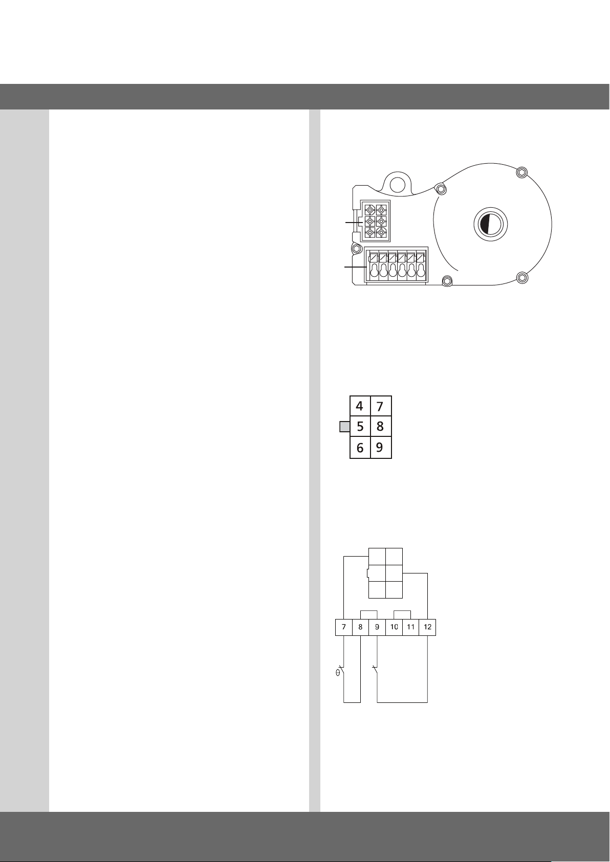
5.3 Allocation of connections for absolute
value encoder (plug terminal X11)
A
B
A: AWG plugs
B: AWG plug terminal
Plug terminal X11 (at connection A)
The numbers on the plug are also the wire
numbers.
4: Safety circuit input
5: RS 485 B
6: GROUND
7: RS485 A
8: Safety chain output
9: 12V
DC
Plug terminal B (absolute value encoder only)
C Thermal element in door/
gate operator
D: Emergency hand
operation (emergency
hand crank or emergency
hand chain)
C D
The end position system will be recognised automatically by
the control during initial use. If replaced at a later date, the
relevant end position system must be selected in a parameter
setting in the INPUT operating mode.
CS 310 Gate Controls / Rev.B 1.0 – 7
Page 44
Initial operation
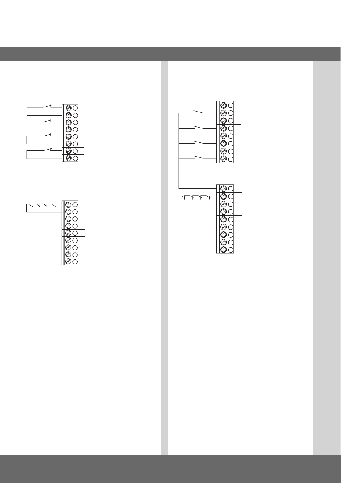
5.4 Connection arrangement for mechanical
limit switches (terminals X15 and X2)
Terminal block X15
1
1
2
2
3
4
3
5
6
4
7
8
Terminal block X2
5
7
6
8
B2
B1
W
Connection example for solution with 6 leads
Terminal blocks X11 and X2
1
1
2
2
3
4
3
5
6
4
7
8
B2
B1
5
8
6
7
W
V
U
V
1
Limit switch OPEN
2
Limit switch CLOSE
3
Pre-limit switch OPEN
4
Pre-limit switch CLOSE
5
Thermal overload protection for motor
6
Emergency operation (normally closed contact)
7
Safety limit switch CLOSE
8
Safety limit switch OPEN
The end position system will be recognised automatically by
the control during initial use. If the connection is changed at a
later date, the relevant end position system must be selected
in a parameter setting in the INPUT operating mode.
U
8 – CS 310 Gate Controls / Rev.B 1.0
Page 45
GB
5.5 Connection arrangement for command
devices
CAUTION!
Danger of injury due to uncontrolled movement of
the door/gate!
Install command devices for deadman operation within
site of the door/gate, but beyond the danger zone for the
user.
If the command device is not a key switch:
Install it at a height of at least 1.5 m off the ground.
Install it so as to make it inaccessible to the general
public.
Terminal block X3
- DOWN-SWITCH
- Impulse button1
UP-SWITCH / STOP / DOWN-SWITCH
4-lead solution
- DOWN-SWITCH
- UP-SWITCH
- STOP button
Key switch UP / DOWN
- DOWN
- UP-SWITCH
- STOP button
- Emergency off, slack rope switch,
wicket door contact, draw in
protection
5.6 Connection examples for command
devices (terminal block X3)
UP / STOP / DOWN buttons
6-lead solution
- DOWN-SWITCH
- UP-SWITCH
- UP
Impulse button
(sequence control)
- impulse button
- STOP button
CS 310 Gate Controls / Rev.B 1.0 – 9
Page 46
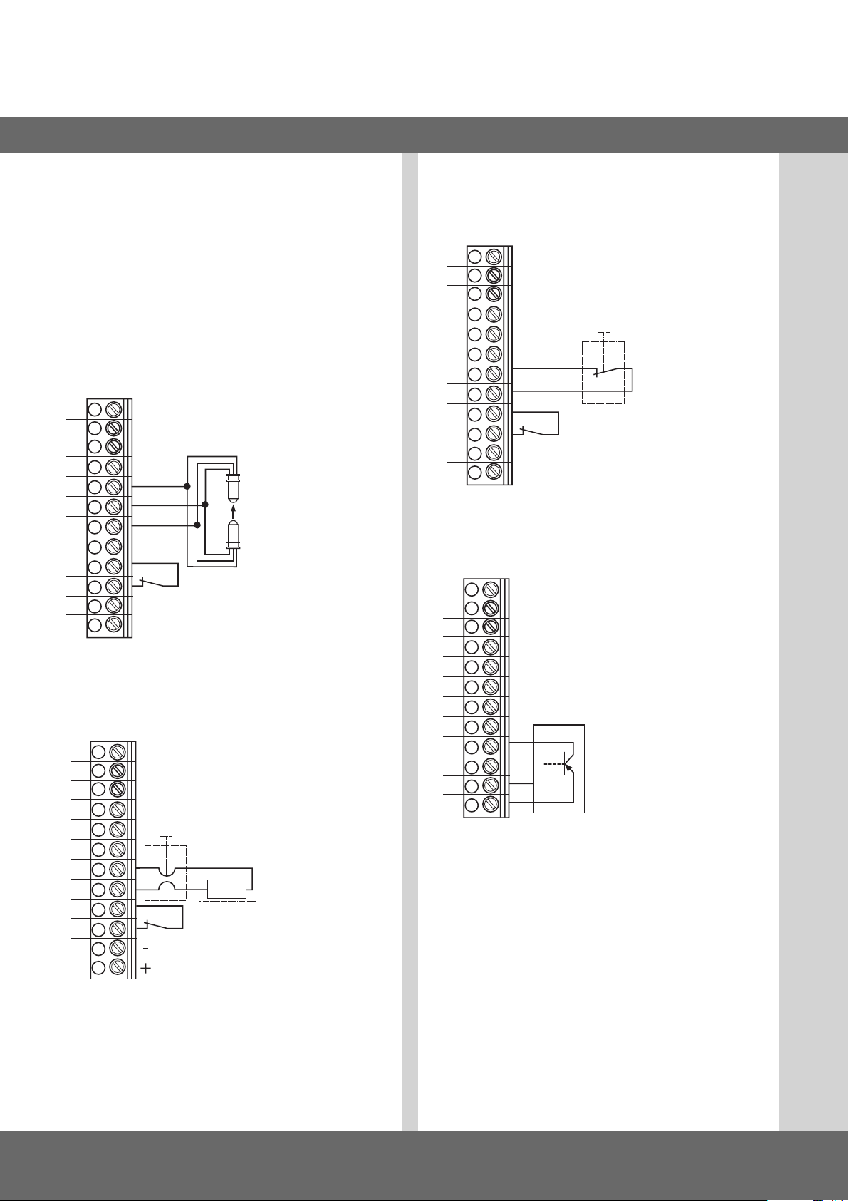
1
Initial operation
5.7 Connection arrangement for safety
devices
Whenconnectedforthersttime,thesystemrecognises
the safety edge protection automatically. If the connection
is changed at a later date, the appropriate system must be
selected in a parameter setting in the INPUT operating mode.
Terminal block X4
(for optoelectronic safety edge protection)
12
11
10
9
8
7
wt
gr
br
- safety edge protection
OPTO
6
5
4
3
2
1
Terminal block X4
(for 8.2 kOhm safety edge protection)
12
11
10
-
+
- photoelectric
drive-through
- 24 V DC / 250 mA
1
2
9
8
7
6
5
4
3
8k2
- safety edge
protection
- photoelectric
drive-through
1
2
- 24 V DC / 250 mA
Terminal block X4
for pneumatic safety edge protection - pressure switch test:
- testing automatically active
12
11
10
9
8
7
6
- safety edge
protection
5
4
3
2
1
Terminal block X4
(for three-wire photoelectric barrier)
12
11
10
-
+
- photoelectric
drive-through
- 24 V DC / 250 mA
1
2
9
8
7
6
5
4
3
2
GND
24V
- Three-wire photoelectric
barrier
1
2
1
effective in down direction
2
for external switching devices (connection to terminals 1 and 2)
wt: white
gr: green
br: brown
10 – CS 310 Gate Controls / Rev.B 1.0
Page 47
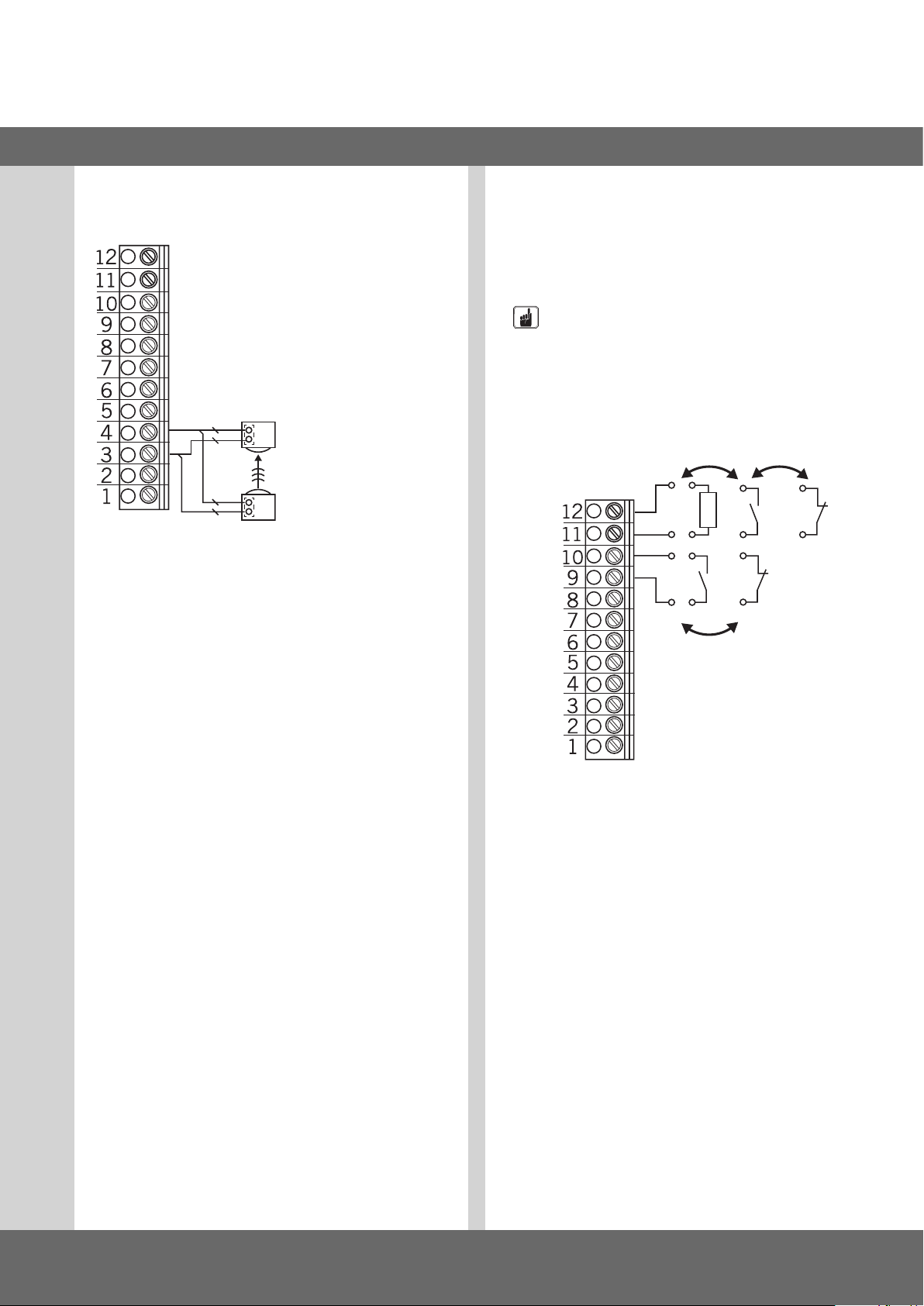
GB
**
Terminal block X4
(for MFZ two-wire photoelectric barrier)
2121
R
T
R: Receiver
T: Transmitter
Whenconnectedforthersttime,thesystemrecognises
the safety edge protection automatically. If the connection is
changed at a later date, the relevant system must be selected
in a parameter setting in the INPUT operating mode.
Terminal block X4
Programmable inputs
Input 1: Terminal 9 + 10
Input 2: Terminal 11 + 12
NOTICE
Danger of damage to the circuit board due to
incorrect connection!
Inputs 1 and 2 have a different reference potential and they
must NOT be operated from the same potential!
IN2
8K2
12V
IN1
24V
*
* either/or
The type of wiring depends on the parameter settings for both
inputs in INPUT mode.
CS 310 Gate Controls / Rev.B 1.0 – 11
Page 48
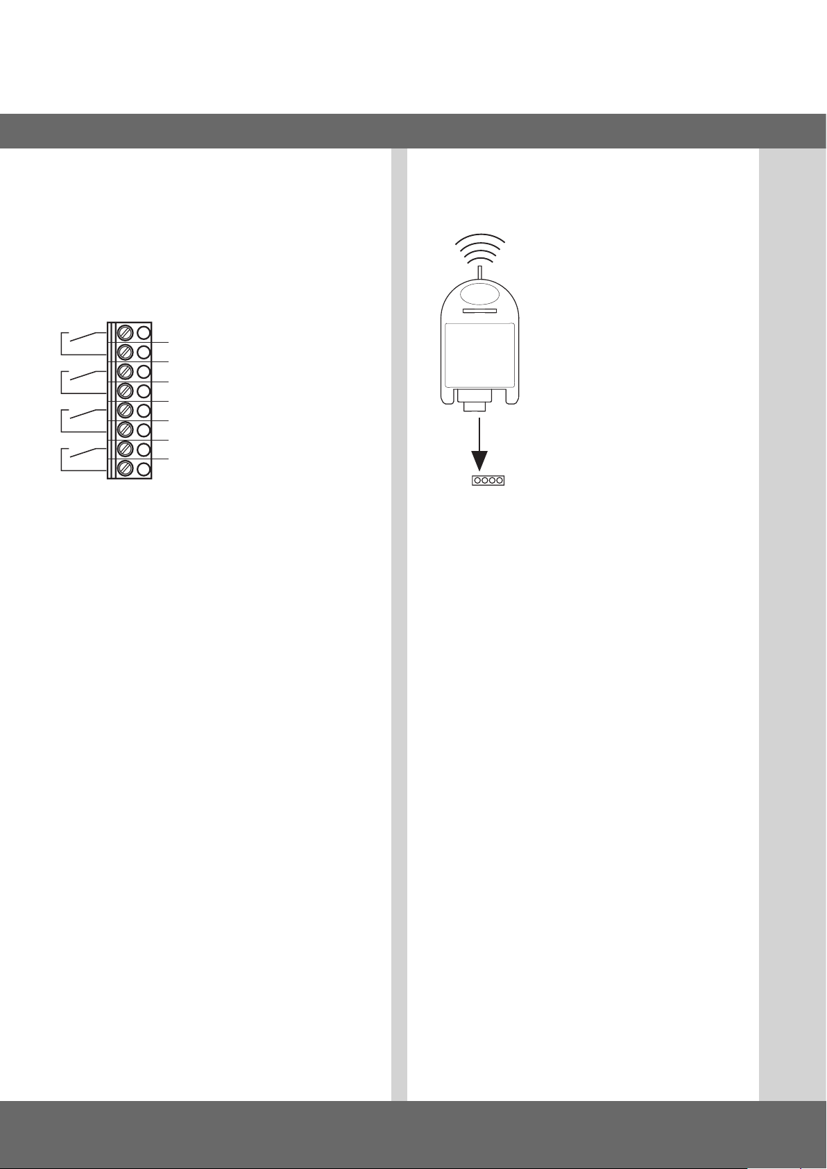
Initial operation
5.8 Connection arrangement for relay
outputs
Terminal block X5
(potential-free switching contacts)
− Assignment of functions in INPUT mode
− Setting for each single relay
1
- relay 1
2
3
- relay 2
4
5
- relay 3
6
7
- relay 4
8
5.9 CS radio
Terminal block X9
Connection
Insert the plug-in receiver into plug-in
socket X9.
Teaching-in the transmitter codes
Presstheprogrammingbuttonbriey
(<1.6 seconds). The programming mode is
activated.TheLEDashes.
Press the required channel button on
your transmitter.
Once the remote control has saved the
X9
It is possible to teach-in up to 15 transmission codes. If all
memoryspacesarefull,theLEDashesrapidly.
transmission code, the LED lights up to
approx. 4 seconds.
Selectively deleting a transmission code
Presstheprogrammingbuttonbriey(<1.6seconds).
Theprogrammingmodeisactivated.TheLEDashes.
Keep the programming button pressed for longer than
1.6seconds.Thedeletemodeisactivated.
TheLEDashesveryfast.
Press the required channel button on your transmitter.
The LED lights up for approx. 4 seconds if the appropriate
transmission code has been deleted.
Thedeletionprocedurecanbecancelledbybrieypressing
the programming button.
Reset (completely delete memory)
Presstheprogrammingbuttonbriey(<1.6seconds).
Theprogrammingmodeisactivated.TheLEDashes.
Keep the programming button pressed for longer than
1.6seconds.
Thedeletemodeisactivated.TheLEDashesveryfast.
Press the programming button again for more than
1.6seconds.
The LED lights up for approx. 4 seconds if all memory spaces
have been deleted.
12 – CS 310 Gate Controls / Rev.B 1.0
Thedeletionprocedurecanbecancelledbybrieypressing
the programming button.
Page 49

6. Setting the end positions
GB
6.1 Checking the direction of rotation /
direction of travel
Changing to ADJUSTMENT mode
Press button (P) until ADJUSTMENT appears.
Checking the direction of travel
If you press button (+), the door/gate should open; if you
press button (-), the door/gate should close.
If it is correct, continue with setting the end positions.
Changing the direction of rotation
If the direction of rotation needs to be changed, proceed as
follows.
Pressbuttons(+)and(-)atthesametimefor>5seconds.
The display shows ROT FIELD. Any end positions that have
been saved will be deleted. Continue with setting the end
positions.
6.2 Setting the electronic end position using
the setting button on the circuit board
Changing to ADJUSTMENT mode
Press button (P) for approx. 5 seconds.
TheredLEDashesslowly.
Setting the OPEN end position
Press the (+) button to move the door/gate to the OPEN end
position.
Save the end position setting by pressing button (P) and by
additionally pressing the (OPEN) button.
TheredLEDashesrapidlyforapprox.1second.
Setting the CLOSED end position
Press the (UP/DOWN) button to move the door/gate to the
CLOSED end position.
Save the end position setting by pressing button (P) and by
additionally pressing the (CLOSE) button.
TheredLEDashesrapidlyforapprox.1second.
ADJUSTMENT mode is automatically exited.
The red LED goes out.
N.B.
− ADJUSTMENT mode is exited automatically after approx.
10secondsifnoneofthebuttonsarepressed.
− Whencarryingoutadjustmentsforthersttime,itis
necessary to teach-in both end positions, as otherwise
normal operation is not possible.
− If an end position is corrected, the ADJUSTMENT menu can
be exited by pressing button (P) once the teaching-in of the
special end position has been completed.
− After programming the limit switches, the teach-in of
the system running time is carried out automatically. The
display shows a TEACH IN RUN. The functions of the control
are the same as in automatic mode.
CS 310 Gate Controls / Rev.B 1.0 – 13
Page 50

Setting the end positions
6.3 Setting the electronic end position using
the CSI 3-button input unit
Change to ADJUSTMENT mode
Press the (STOP) button for approx. 5 seconds.
TheredLEDashesrapidly.
LetgooftheSTOPbuttonbriey.
The red LED lights up for 2 seconds.
Keep the (STOP) button pressed for approx. 5 seconds
during this time.
TheredLEDashesslowly.
Let go of the (STOP) button.
Setting the OPEN end position
Press the (+) button to move the door/gate to the OPEN end
position.
Save the end position setting by pressing the (STOP) button
and by additionally pressing the (OPEN) button.
TheredLEDashesrapidlyforapprox.1second.
Set the CLOSED end position
Press the (UP/DOWN) button to move the door/gate to the
CLOSED end position.
Save the end position setting by pressing the (STOP) button
and by additionally pressing the (CLOSE) button.
TheredLEDashesrapidlyforapprox.1second.
ADJUSTMENT mode is exited automatically.
The red LED goes out.
N.B.
− ADJUSTMENT mode is exited automatically after approx.
10secondsifnoneofthebuttonsarepressed.
− Whencarryingoutadjustmentsforthersttime,itis
necessary to teach-in both end positions, as otherwise
normal operation is not possible.
− If an end position is corrected, the ADJUSTMENT menu can
be exited by pressing the (STOP) button once the teachingin of the special end position has been completed.
− After programming the limit switches, the teach-in of the
system running time is carried out automatically.
The display shows TEACH IN RUN. The functions of the
control are the same as in automatic mode.
6.4 Setting the electronic end position using
the LCD display
NOTICE
Damage to property or irreparable damage due to
incorrect installation!
The display must be plugged in only if it is disconnected
from the power supply and at zero voltage. Only one MFZ
display must be used:
At plug-in socket X8: LCD Display Standard (#206023)
At plug-in socket X14: LCD Display RS 485
(#1700004793)
At plug-in socket X16: LCD Display MSBUS
(#1700015335)
Changing to ADJUSTMENT mode
Press button (P) until ADJUSTMENT appears.
Setting the OPEN end position
Press the (+/-) button to move the door/gate to the desired
OPEN end position.
Save the end position setting by pressing button (P) and by
additionally pressing the (+) button.
Setting the CLOSED end position
Press the (+/-) button to move the door/gate to the desired
OPEN end position.
Save the end position setting by pressing button (P) and by
additionally pressing the (-) button.
Exit the ADJUSTMENT mode by pressing button (P).
N.B.
− Whencarryingoutadjustmentsforthersttime,itis
necessary to teach-in both end positions, as otherwise
normal operation is not possible.
− If an end position is corrected, the ADJUSTMENT menu can
be exited by pressing button (P) once the teaching-in of the
special end position has been completed.
− After programming the limit switches, the teach-in of the
system running time is carried out automatically. The display shows TEACH IN RUN. The functions of the control are
the same as in automatic mode.
14 – CS 310 Gate Controls / Rev.B 1.0
Page 51

GB
6.5 Setting the electronic intermediate end
position using the LCD display
In AUTOMATIC mode, move the door/gate to the
desired position
Press the (+/-) button to move the door/gate to the desired
position (e.g. before-end switch OPEN).
Changing to INPUT mode
Press button (P) until INPUT appears.
Press buttons (+ and -) > 2 seconds to activate INPUT.
Saving the intermediate end position OPEN - BES-OPEN
Press buttons (+/-) until BES OPEN appears. The value
stands at A.
Press button (P) to adopt the current door/gate position as
an intermediate end position.
Saving the intermediate end position by pressing button (P)
again.
Exiting INPUT mode
Press buttons (+ and -) > 1 second to deactivate INPUT.
N.B.
− ADJUSTMENT mode is not exited automatically. To return
to normal operating mode, ADJUSTMENT mode must be
exited by pressing button (P).
− If an intermediate end position requires to be corrected, the
teach-in value can be altered in the INPUT menu or set to A
again to allow a new teach-in procedure to be carried out.
Changing to AUTOMATIC mode
Press button (P) until AUTOMATIC appears.
6.6 Setting the mechanical end position
Changing to ADJUSTMENT mode
Press button (P).
Setting the OPEN and CLOSED end position
REFERENCE
The procedure for setting the end positions is described in
separate documentation for mechanical limit switches.
Exit the ADJUSTMENT mode by pressing button (P).
CS 310 Gate Controls / Rev.B 1.0 – 15
Page 52
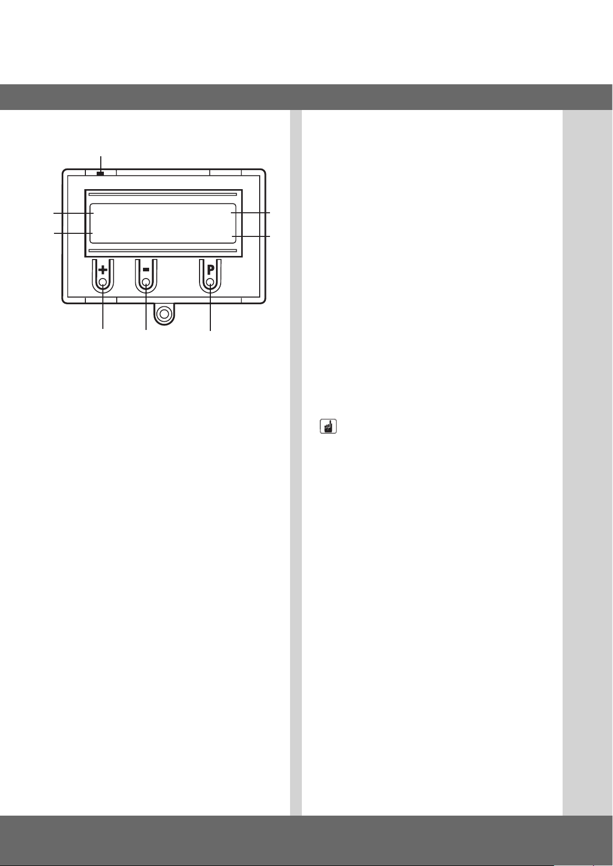
7. Programming with the LCD monitor
7.1 Overview of the LCD monitor
H
A
B
Key:
A: mode of operation / diagnostic info
B: parameter / diagnostic info
C: (+) button
D: (-) button
E: (P) button
F: value / status
G: value / status
H: jumper
AUTOMATIC O
STANDBY
C D E
ADJUSTMENT, INPUT and DIAGNOSIS modes are exited
automatically 20 seconds after the last button was pressed,
and the control then goes into AUTOMATIC mode.
Operating mode 1: AUTOMATIC
The door/gate system is operated in the AUTOMATIC
G
F
operating mode.
Display:
− displays the function being carried out
− displays any error messages
If the “SELF LOCK“ parameter is set to MOD2 or MOD3 in
the input menu, the display changes from AUTOMATIC to
MANUAL.
Operating mode 2: ADJUSTMENT
In the ADJUSTMENT mode, the OPEN/CLOSED end positions
are set.
NOTICE
Malfunctions can occur as a result of incorrect
operation of the control!
In the ADJUSTMENT mode of operation, the operator does
not switch off when the end position is reached. The door/
gate can be damaged if driven beyond the end position.
7.2 LCD monitor, modes of operation
The controls have four modes of operation with the LCD
monitor:
1. AUTOMATIC
2. ADJUSTMENT
3. INPUT
4. DIAGNOSIS
If the jumper H is pulled, the (+) button, the (-) button and
the (P) button have no function. The display still functions.
After switching on the control, it is in INITIALISATION mode.
The display shows INIT PHASE and the control is not yet ready
for use. This phase lasts approx. 5 seconds.
16 – CS 310 Gate Controls / Rev.B 1.0
Fine adjustments can be made in the INPUT operating mode.
Display:
- displays the end position value
Operating mode 3: INPUT
In the INPUT operating mode, the values of various
parameters can be altered.
Display:
− displays the selected parameter
− displays the programmed value /status
Page 53

Operating mode 4: DIAGNOSIS
IntheDIAGNOSISoperatingmode,door/gate-specicchecks
can be queried.
Display:
− displays the check
− displays the checking status
GB
CS 310 Gate Controls / Rev.B 1.0 – 17
Page 54
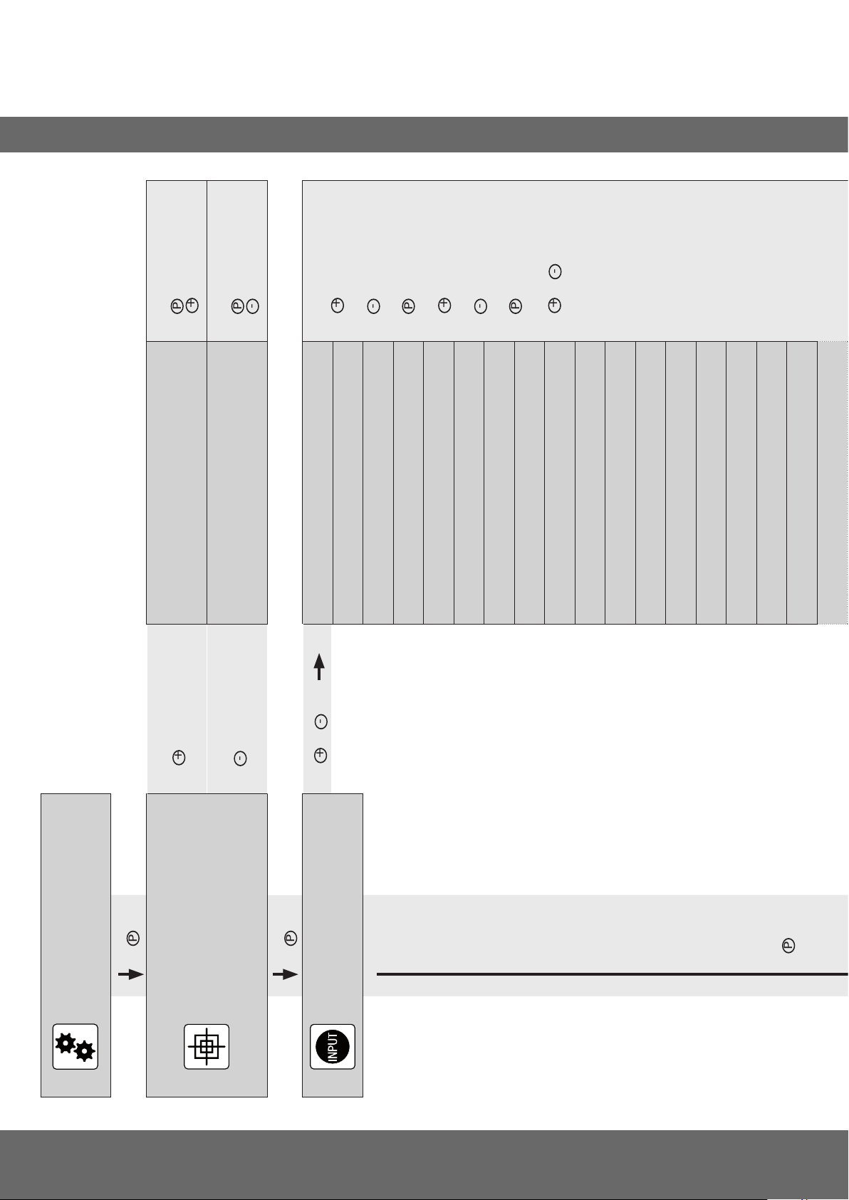
8. Navigator (LCD monitor only)
P
+
P
+
-
P
-
P
+
-
+
-
P
+
-
P
+
-
P
+
-
P
> 1 sec.
> 1 sec.
Keep pressed and
MAIN UP
Save door/gate position:
ADJUSTMENT
Save door/gate position:
ADJUSTMENT
Keep pressed and
>1 sec.
MAIN DOWN
> 2 sec.
> 2 sec.
Scroll up through menu:
Scroll down through menu:
Select value:
INPUT
DEUTSCH :
INPUT
FINE-UP : 0
INPUT
FINE-DOWN : 0
> 1 sec.
INPUT
BES-OPEN : A
Increase value:
INPUT
Decrease value:
Save value:
INPUT
OPEN TIME : 0
INPUT
BES-CLOSE : A
START WARN. : 0
INPUT
and
Return to INPUT:
INPUT
REVERS POINT : ES-CLOSE + 50
INPUT
INPUT
SCS : A
INPUT
SCS FUNC : MOD1
INPUT
INPUT
FAST CL. : MOD1
INPUT
RELAY 4 : MOD14
INPUT
FOREWARNING : 0
INPUT
AUT.CLOSE : MOD1
T-LI. REST : MOD1
SCS REV : MOD1
PHOTOELECTRIC BARRIER / LIGHT BARR. : A
AUTOMATIC
STANDBY
>1 sec.
-> Position door/gate OPEN
-> Position door/gate CLOSED
ADJUSTMENT
STANDBY
>1 sec.
> 2 sec.
and
INPUT
>1 sec.
18 – CS 310 Gate Controls / Rev.B 1.0
Page 55
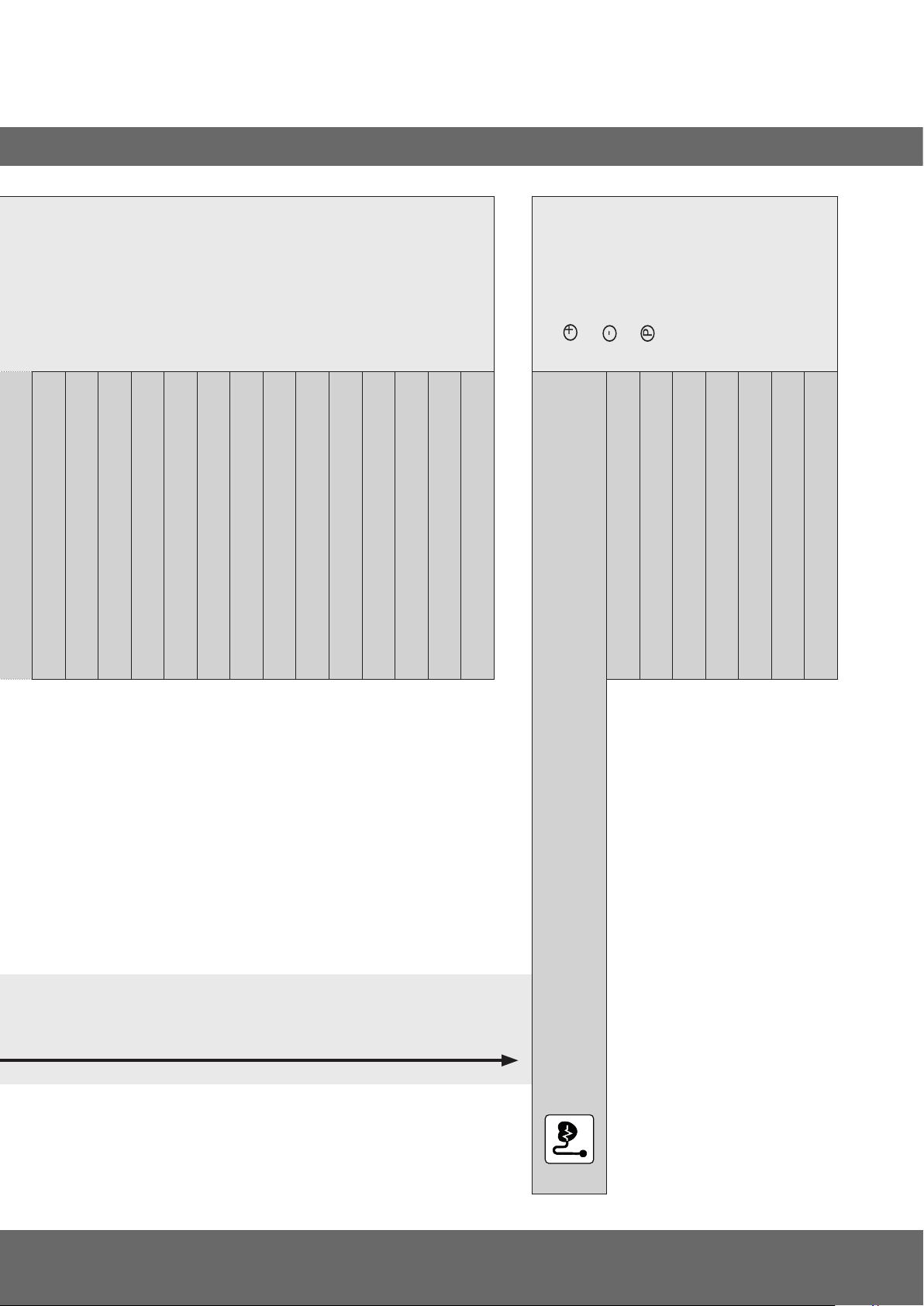
+
> 2 sec.
-
P
> 2 sec.
Scroll up through menu:
Scroll down through menu:
Return to AUTOMATIC:
GB
Only queries are possible.
INPUT
LB FUNC : MOD1
INPUT
PEB POINT : ES-CLOSE
INPUT
: MOD1
IMPULS
INPUT
INPUT 1 : MOD1
INPUT
INPUT 2 : MOD1
INPUT
SCS3 : MOD1
INPUT
SCS4 : MOD1
INPUT
IMPULS INPUT : OFF
SWITCH CLOCK : OFF
LIGHT BARR. : ON
STOP CHAIN : ON
STOP : ON
CYCLE : 4
AWG : 2599
UPPER SWITCH : ON
LOWER SWITCH : ON
UP-SWITCH : OFF
INPUT 1 : OFF
DOWN-SWITCH : OFF
INPUT
RESTART : OFF
INPUT
INPUT
POWER : ON
INPUT
REVERS.TIME : 300
INPUT
LIMIT SWITCH : A
INPUT
RUNNINGTIME : A
SELF LOCK : MOD1
FACTORY SET. : OFF
DIAGNOSIS
SCS 1/2/3/4 : ON
ERROR MEMORY : ERROR
CS 310 Gate Controls / Rev.B 1.0 – 19
Page 56

9. Overview of functions
9.1 Automatic operating mode
Display Description
AUTOMATIC
TEACH IN RUN
AUTOMATIC
OPEN
AUTOMATIC
CLOSE
AUTOMATIC
STANDBY
AUTOMATIC O
STANDBY
AUTOMATIC o
STANDBY
AUTOMATIC U
STANDBY
AUTOMATIC u
STANDBY
AUTOMATIC r
STANDBY
Automatic teach-in of the running time
The door/gate is driven to the OPEN end position
The door/gate is driven to the CLOSED end position
The door/gate stands between the end positions
The door/gate stands at the OPEN end position
The door/gate stands at the PART OPEN position (“before-end position“ top)
The door/gate stands at the CLOSED end position
The door/gate stands at the PART CLOSED position (“before-end position“ bottom)
The door/gate is in the PART OPEN position (“before end position” OPEN).
If the “SELF LOCK“ parameter is set to MOD2 or MOD3 in the input menu, the display changes from AUTOMATIC to MANUAL.
Display Description
MANUAL
MAIN UP
MANUAL
MANUAL DOWN
MANUAL
STANDBY
The door/gate is driven to the OPEN end position
The door/gate is driven to the CLOSED end position
The door/gate stands between the end positions
20 – CS 310 Gate Controls / Rev.B 1.0
Page 57
9.2 Input operating mode
Function Description Setting options Factory settings
GB
DEUTSCH Select the menu language DEUTSCH
FINE-UP Fine adjustment of OPEN end position to the programmed OPEN end position.
Only visible in systems with electronic limit switch.
FINE-DOWN Fine adjustment of CLOSED end position to the programmed CLOSED end position.
Only visible in systems with electronic limit switch.
BES-OPEN Setting the before-end position switch point for the OPEN direction (referred to the
programmed CLOSED end position (CLOSED end position = AWG value 0).
Only visible in systems with electronic limit switch.
Automatic teach-in of position:
“6.5 Setting the electronic intermediate end position using the LCD display“
BES-CLOSE Setting the before-end position switch point for the CLOSED end position to the
programmed CLOSED end position.
Only visible in systems with electronic limit switch.
Automatic teach-in of position:
“6.5 Setting the electronic intermediate end position using the LCD display“
ENGLISH
FRENCH
ESPANOL
NEDERLANDS
POLSKI
CESKY
ITALIANO
-250 – 250 0
-250 – 250 0
0 = ES-CLOSE – ESOPEN, A
A, 0 = ES-CLOSE – ESOPEN
DEUTSCH
A - teach-in
A - teach-in
OPEN TIME After the door/gate has opened, it runs back in the CLOSE direction after the set time
START
WARN.
FOREWARNING
AUT.CLOSE : MOD 1: AUT.CLOSE from UPPER end position
QUICK
CLOSE
has elapsed.
Notice:
By pressing the DOWN-SWITCH during the open time, the closing run is started.
By pressing the UP-SWITCH or STOP button during the open time, the closing run is
restarted.
If an automatic closing run is interrupted by the closing edge contacts (SCS) the open
time is twice as long, and after 3 attempts, automatic closing (AC) is aborted.
The start warning is carried out before each run. 0 - 10 seconds
The forewarning is activated before carrying out an automatic closing run or closing
in impulse mode.
Notice: This time is added to the start warning.
MOD 2: AUT.CLOSE from SECT. SWITCH
MOD 3: AUT.CLOSE from UPPER end position and part open (SECT. SWITCH)
MOD 4: AUT.CLOSE from all door/gate positions
MOD1 : The open time proceeds as usual.
MOD2: The open time is cut short after the photoelectric barrier has been passed
(door/gate closes immediately).
MOD3: The open time is aborted after the photoelectric barrier is interrupted for
a minimum period (2 sec.) (suppression through persons).
0 - 3600 seconds
0 = AC off
0 = off
0 - 120 seconds 0 = Off
MOD1
MOD2
MOD3
MOD4
MOD1
MOD2
MOD3
0 = AC off
0
MOD1
MOD1
CS 310 Gate Controls / Rev.B 1.0 – 21
Page 58
Overview of functions
Function Description Setting options Factory settings
RELAY 1 A relay module from 1 - 34 can be assigned to all four relays.
MOD1: Redlight1)ashesduringforewarningandisONduringdoor/gaterun
MOD2: (Redlight2)ashesduringforewarningandduringdoor/gaterun
MOD3: (Red light 3) is ON during forewarning and during door/gate run
MOD4: Impulse signal when there is an UP command
MOD5: Error message
MOD6: OPEN end position
RELAY 2 MOD1 – MOD34 MOD7
RELAY 3 MOD1 – MOD34 MOD28
RELAY 4 MOD1 – MOD34 MOD14
MOD7: CLOSED end position
MOD8: OPEN end position negated
MOD9: CLOSED end position negated
MOD10: Before-end position OPEN
MOD11: Before-end position CLOSED
MOD12: Before-end position CLOSED to CLOSED end position
MOD13: Magnetic lock function
MOD14 Brake
MOD15: Brake negated
MOD16: Brake also remains ON during open time
MOD17: SCS activated or test error
MOD18: (Redlight4)ashesduringforewarningandisOFFduringdoor/gaterun
MOD19: Before-end position OPEN to OPEN end position
MOD20: Activation of optoelectronic transmission system
MOD21: Test of draw-in protection before opening run
(additional module required)
MOD22: Test of external safety devices before closing run
(additional module required)
MOD23: (Green light) is ON during OPEN end position, OFF during forewarning
and OFF during door/gate run
MOD24: Capacitor circuit for 230V 1 phase operators
MOD25: Yard light function 2 minutes after OPEN command
(including indirectly through impulse)
MOD26: Activation of radio transmission system
MOD27: Impulse when OPEN end position is reached
MOD28: Relay OFF
MOD29: Door/gate moves to OPEN
MOD30: Door/gate moves to CLOSED
MOD31: Maintenance
MOD32: Battery operation
MOD33: Battery operation not possible
MOD34: Fire alarm system signal (BMA signal)
MOD1 – MOD34 MOD6
T-LI. REST Switchestrafclights
MOD1: In standby mode: OFF
MOD2: In standby mode: ON
MOD3: In standby if OFF for 5 minutes
SCS MOD1: OSE
MOD2: 8K2
MOD3: SCS as NC with testing
SCS FUNC MOD1: Stop + reverse
MOD2 Stop + 2-second reversing movement
Notice: If reversing not permitted, the door/gate merely stops.
SKS REV MOD1: Stop + reverse between upper end position (EO) and RP, stop between
reverse point (RP) and lower end position (EU)
MOD2 Stop + reverse between upper end position (EO) and RP, no action
between reverse point (RP) and lower end position (EU)
MOD3: Stop + reverse between upper end position (EO) and lower end position
(EU)
Notice: In systems with mechanical limit switches the before-end position CLOSED
serves as the reverse point (RP).
22 – CS 310 Gate Controls / Rev.B 1.0
MOD1 – MOD3 MOD1
A - self teach-in
MOD1 – MOD 3
MOD1 – MOD2 MOD1
MOD1 – MOD3 MOD1
A - self teach-in
Page 59

Function Description Setting options Factory settings
GB
REVERS.
POINT
PHOTOELECTRIC
BARRIER /
LIGHT BARR.
LB FUNC CLOSING OPENING
PEP POINT The photoelectric barrier is not evaluated between the ES-CLOSE and the PEB POINT.
IMPULSE MOD1: OPEN – Stop – Close – Stop
INPUT 1 MOD1: Sect. switch button
Reverse point (RP) before the CLOSED end position is reached.
Only visible in systems with electronic limit switch.
MOD1: MFZ 2-wire
MOD2: NC contact
door/gate movement door/gate movement
MOD1: Stop + reverse No action
MOD2: Stop + reversing movement No action
MOD3: STOP No action
MOD4: STOP STOP
MOD5: Stop + reverse Travel suppression
(Door/gate frame function).
Only visible in systems with electronic limit switch.
MOD2: OPEN only
MOD3: OPEN only, Stop when door/gate moving
MOD4: OPEN only, inactive during door/gate movement
MOD5: CLOSE from upper end position (EO), otherwise OPEN
MOD2: PART OPEN switch (SECT. SWITCH)
MOD3: AUT.CLOSE switch
MOD4: External CLOCK (permanently open)
MOD5: Switch for keeping the door/gate open / alarm
MOD6: BMA switch (emergency closing) NO
MOD7: BMA switch (emergency closing) NC
MOD8: BMA switch (emergency opening) NO
MOD9: BMA switch (emergency opening) NC
MOD10: Ventilation button (PART CLOSE)
MOD11: Automatic closing button
ES-CLOSE + 0 - 250 ES-CLOSE + 50
A - self teach-in
MOD1 – MOD2
MOD1 – MOD5 MOD1
A, 0 = ES-CLOSE –
ES-OPEN
MOD1 – MOD5 MOD1
MOD1 – MOD11 MOD1
A - self teach-in
0
INPUT 2 MOD1: NOT active
SCS3 MOD 1: Not in use
SCS4
MOD2: Wicket door/gate switch
8K2 Stop in case of deviation
MOD3: Switching strip OPEN
8K2 Stop and reverse
MOD4: Switching strip OPEN
8K2 Stop and reversing movement
MOD5: Battery operation
MOD 2: SCS CLS.
MOD 3: SCS OPEN
MOD 4: Stop
Only to be used in conjunction with the wireless signal transmission plug-in circuit
card in terminal X20.
MOD 1: Not in use
MOD 2: SCS CLS.
MOD 3: SCS OPEN
MOD 4: Stop
Only to be used in conjunction with the wireless signal transmission plug-in circuit
card in terminal X20.
MOD1 - MOD5 MOD1
MOD1 - MOD4 MOD1
MOD1 - MOD4 MOD1
CS 310 Gate Controls / Rev.B 1.0 – 23
Page 60

Overview of functions
Function Description Setting options Factory settings
RUNNING
TIME
POWER Automatic power monitoring ON
REVERS.
TIME
LIMIT
SWITCH
SELF LOCK MOD1: Automatic operation
RESTART Control is restarted if function is activated. ON
FACTORY SET. Resets all parameters of the control to the factory settings.
Monitoring the maximum running time for an open and close movement.
After programming the limit switches, the teach-in of the system running time is
carried out automatically. In the event of a 20% deviation (in both directions) an
ERROR RUNTIME appears.
After the automatic teach-in, the running time can be manually changed.
Standing time at every change of direction. The reversal time when the switching strip
or the photoelectric barrier is activated during the closing movement amounts to a
third of the programmed time.
MOD 1: AWG
MOD 2: Mechanical limit switches
MOD2: Manual operation for OPEN + CLOSE with CESD evaluation
MOD3: Manual operation for CLOSE
MOD4: Manual operation for CLOSE
MOD5: Manual operation for OPEN + CLOSE with no CESD evaluation
A = Automatic
1 - 300 seconds
OFF
300 -
2000 milliseconds
A - self teach-in
MOD1 – MOD 2
MOD1 – MOD5 MOD1
OFF
A
ON
300 milliseconds
A - self teach-in
OFF
Explanation of the relay modes:
A. Trafclightfunctions
MOD Description
MOD 1 Redtrafclight1 ON / OFF * OFF Flashing Lit up
MOD 2
MOD 3
MOD 18 Redtrafclight4 OFF OFF Flashing OFF
MOD 23
Redtrafclight2 ON / OFF * OFF Flashing Flashing
Redtrafclight3 ON / OFF * OFF Lit up Lit up
Greentrafclight OFF Lit up OFF OFF
CLOSED end
position
OPEN end position
Forewarning Door/gate run
* depending upon parameter T-LI. REST
24 – CS 310 Gate Controls / Rev.B 1.0
Page 61

B. Position messages
MOD Description Remarks
MOD 6 OPEN end position The relay closes the contact when the door/gate is in the OPEN end position.
MOD 7 CLOSED end position The relay closes the contact when the door/gate is in the CLOSED end position.
MOD 8 Not OPEN end position The relay closes the contact when the door/gate is not in the OPEN end position.
MOD 9 Not CLOSED end position The relay closes the contact when the door/gate is not in the CLOSED end position.
GB
MOD 10 Before-end position OPEN / PART OPEN The relay closes the contact when the door/gate is in the before-end position
MOD 11 Before-end position CLOSED The relay closes the contact when the door/gate is in the before-end position
MOD 12 Before-end position CLOSED to CLOSED end position The relay closes the contact when the door/gate is in the area between the end
MOD 19 Before-end position OPEN to OPEN end position The relay closes the contact when the door/gate is in the area between the OPEN
OPEN/partOPEN.
CLOSED.
position CLOSED and the before-end position CLOSED.
end position and the before-end position OPEN.
C. Impulse signals
MOD Description Remarks
MOD 4 Impulse when there is an OPEN command The relay closes the contact for 1 second when the door/gate receives an OPEN
MOD 27 Impulse when OPEN end position is reached The relay closes the contact for 2 seconds when the door/gate reaches the OPEN end
command. This impulse can be used to control lights, for instance.
position.
This impulse can be used, for instance, to open a following photoelectric barrier.
D. Brake functions
MOD Description Remarks
MOD 14 Brake Theswitchingcontactofthebrakerectiersisactivatedviatherelaytoachievea
MOD 15 Brake negated Theswitchingcontactofthebrakerectiersisactivatedviatherelaytoachievea
quicker brake function. The contact is closed, and the brake released as a result, as
soon as the door/gate moves (zero current brake).
quicker brake function. The contact is closed, and the brake released as a result, as
soon as the door/gate moves (zero current brake).
CS 310 Gate Controls / Rev.B 1.0 – 25
Page 62

Overview of functions
MOD Description Remarks
MOD 16 Brake remains ON during open time Theswitchingcontactofthebrakerectiersisactivatedviatherelaytoachievea
quicker brake function. The contact is closed, and the brake released as a result, as
soon as the door/gate moves (zero current brake). To obtain a smoother stop by the
door/gate in the upper end position, the switching contact is not switched in the
OPEN end position (OPEN TIME).
E. Error messages
MOD Description Remarks
MOD 5 Error message The relay closes the contact when a stop command is given or an error occurs.
MOD 17 SEP activated The relay opens the contact when the switching strip is activated. An error in
All errors described in Section 10 result in activation of the relay.
switching strip or an unsuccessful test is shown via MOD 5.
F. Functions for external accessories
MOD Description Remarks
MOD 13 Magnetic lock function The relay closes before every door movement. When the door is stationary, the relay
MOD 20 Activation of optoelectronic transmission system Before every CLOSE command, the optoelectronic transmission system is activated
MOD 21 Test of draw-in protection The relay generates a test signal when the CLOSED end position is reached and
MOD 22 Test of external safety devices The relay generates a test signal when the OPEN end position is reached and
MOD 24 Capacitor At every operator command the relay closes for approx. 1 second. With the aid of this
MOD 25 Yard light function At every OPEN command, the relay is closed for 2 minutes and can therefore be used
MOD 26 Activation of radio transmission system Before every CLOSE command the radio transmission system is activated by an
MOD 28 Relay OFF The relay is always open.
is open.
A delay of 0.5 seconds is programmed to elapse before each door movement
and remains active for the duration of the closing run. This activation results in a
closing run delay of approx. 0.5 seconds.
expects, as a reaction to the test signal, that the stop circuit is activated.
expects, as a reaction to the test signal, that the switching strip input circuit is
activated.
relay, an additional starting capacitor that is required for AC applications is switched
on in addition, to ensure safe starting of the motor.
to control a light.
impulse. The duration of the activation must be set on the transmission system. This
activation results in a closing run delay of approx. 0.5 seconds.
26 – CS 310 Gate Controls / Rev.B 1.0
Page 63
9.3 Diagnosis / error memory operating mode
Display Meaning condition
GB
ES-OPEN OPEN end position OFF: activated
ES-CLOSE CLOSED end position OFF: activated
UP-SWITCH UP-switch ON: activated
INPUT 1 INPUT 1 (X4 / 9 + 10) ON: activated
DOWN-SWITCH DOWN-SWITCH ON: activated
SCS 1/2/3/4 Safety edge device
SCS 2 = Input 2
IMPULSE Impulse button ON: activated
ON: not activated
ON: not activated
OFF: not activated
OFF: not activated
OFF: not activated
ON: system circuit is closed
OFF: system is interrupted (fault)
OFF: not activated
SWITCH CLOCK Weekly timer ON: activated
P/E BARRIER Photoelectric drive-through barrier ON: circuit closed
STOP CHAIN - EMERGENCY OFF
- Stop systems of the operator
STOP - Stop button on the controls ON: circuit closed
CYCLE Door/gate cycle counter Displays number of door/gate cycles
AWG Absolute value encoder The current limit switch value is shown
ERROR MEMORY Display changes at 2-second intervals ERROR
OFF: not activated
OFF: interrupted (fault)
ON: circuit closed
OFF: interrupted (fault)
OFF: interrupted (fault)
QUANTITY
CYCLE
CS 310 Gate Controls / Rev.B 1.0 – 27
Page 64
10. Errormessagesandrectication
10.1 Error message shown on LCD display
Fault / error message Cause Rectication
System does not respond - No voltage supply - Check the voltage supply of the operator and
Door/gate travels to the CLOSED end position
when the UP button is pressed
door/gate travels to the OPEN end position
when the DOWN button is pressed
FAULT – X - internal software or hardware fault - restart control
STOP CHAIN
ERROR RUNTIME - The programmed running time has been
-Rotatingeldisconnectedwrongly -Checktherotatingeldandestablishclock-
- The stop circuit has been interrupted.
X3 1,2:
Emergency off, slack rope switch, wicket door
contact, draw-in protection
X6 1,2:
Internal On-Off switch
X11 4,8:
Safety circuit for door/gate operator
X2 B1/B2:
Jumper
X3 3,4:
external stop button
X7 1,2:
internal stop button
exceeded
the controls
wiserotatingeldifnecessary
- Check and then close the stop circuit
- Check the path of the door/gate
- Re-programme the running time
ERROR AWG - Communication fault between limit switch
and control
TERM SWITCH FAIL - The door/gate has travelled beyond one of the
end positions
- The end positions have not been programmed
yet
ERROR REVOLUTION - The power monitoring has been triggered - Check that the door/gate can move freely
ERROR DIRECTION -Anincorrectrotatingeldisconnectedto
terminal X1
ERROR SCS CLS. - The closing edge safety device is faulty - Check the safety edge protection and the
- Safety edge protection has been activated - Remove obstruction from path of door/gate
ERROR SCS CLS. 2 - The closing edge safety device is faulty
- Safety edge protection has been activated - Remove obstruction from path of door/gate
ERROR SCS OPEN 2 - The safety edge protection is faulty - Check the safety edge protection and the
- Check the cable and socket connections
- Check and if necessary re-adjust end position
programming
- Reset the power value
-Ensurethataclockwiserotatingeldis
connected
spiral cable
- Check the Safety edge protection and the
spiral cable
spiral cable
28 – CS 310 Gate Controls / Rev.B 1.0
- Safety edge protection has been activated - Remove obstruction from path of door/gate
Page 65

Fault / error message Cause Rectication
GB
ERROR SCS CLS. 3 - The safety edge protection is faulty - Check the safety edge protection and the
- Safety edge protection has been activated - Remove obstruction from path of door/gate
ERROR SCS OPEN 3 - The safety edge protection is faulty
- Safety edge protection has been activated - Remove obstruction from path of door/gate
ERROR SCS CLS. 4 - The closing edge safety device is faulty - Check the safety edge protection and the
- Safety edge protection has been activated - Remove obstruction from path of door/gate
ERROR SCS OPEN 4 - The safety edge protection is faulty
- Safety edge protection has been activated - Remove obstruction from path of door/gate
ERROR SCS TEST
ERROR LIGHT BAR - The photoelectric barrier has been triggered
- The PS is not triggered at the CLOSED end
position
spiral cable
- Check the safety edge protection and the
spiral cable
spiral cable
- Check the safety edge protection and the
spiral cable
-CheckthePSswitch,spiralcableandprole
- Check the setting for the CLOSED end
position
- Check alignment of photoelectric barrier and
photocell beam
ERROR LB TEST
ERROR TRAPIN
- Photocell barrier testing failed - Check alignment of photoelectric barrier and
- Draw-in protection testing (RELAY MOD.21)
failed
photocell beam
- Check cabling
- Check alignment of photoelectric barrier and
photocell beam
- Check cabling
Afterrectifyingthecauseofthefault,thecontrolsmustbedisconnectedbrieyfromthemains!
CS 310 Gate Controls / Rev.B 1.0 – 29
Page 66

Errormessagesandrectication
10.2 Error message through LED indicator
LED H4 (green, circuit card or CSI button)
Error Display LED H6 – Green Remarks
No operating voltage Off No voltage supply
LED H6 (red)
Error message shown on LCD
display
STOP Flashes 1x STOP CHAIN must be closed, operation of door/
ERROR AWG Flashes 2x System stopped, error in transmission protocol,
TERM SWITCH FAIL Flashes 3x System stopped, door/gate operation not
ERROR DIRECTION Flashes 4x System stopped, door/gate operation not
ERROR REVOLUTION Flashes 5x System stopped, acknowledge error with STOP,
ERROR RUNTIME Flashes 6x System stopped, acknowledge error with STOP,
ERROR SCS / PHOTOELECTRIC BARRIER On Travel in deadman CLOSING direction possible,
Display LED H6 – Red Remarks
gate is then possible
acknowledge error with STOP, renewed attempt
possible using buttons
possible, disconnect control from power supply,
re-adjust end positions
possible,changerotatingeld,disconnect
control from power supply
renewed attempt possible using buttons
renewed attempt possible using buttons
check the switching strip
30 – CS 310 Gate Controls / Rev.B 1.0
Page 67

11. Technical data
GB
Housing dimensions: 215 x 275 x 190 mm
Installation: Vertical mounting on the wall,
Power supply via
L1, L2, L3, N, PE:
Fuse protection: 10 A K type
Internal consumption
of control:
Control voltage: 24 V
Control inputs: 24 V
Control outputs: 24 V
RS485 A and B Only for electronic limit switches
Safety circuit /
emergency off:
minimumheightaboveoor=1,100mm
400V,50/60Hz;powerinputmax.2200W-
3.2 A; duty cycle 60% for a maximum running
time of 120 s
max. 750 mA
DC, max. 500 mA; protected by self-
resetting fuse for external sensor systems.
DC, all input connections must be
potential-free; minimum signal duration for
input control command >100 ms
DCmax. 500 mA
RS485level,terminatedwitha120Ω
All input connections must be potential-free;
if the safety circuit is interrupted, no further
electrically powered movement of the operator
is possible, not even in deadman mode
Vibrations: Low-vibration mounting, e.g. on a masonry wall
Type of enclosure IP 65
Weight approx. 1.8 kg
Closing edge safety
bar input
(performance level C):
Photoelectric barrier
(performance level D):
Display (LCD): Only an original MFZ display must be used as
Relay outputs: If inductive loads are connected (e.g. further
Temperature range: Operation -10°C ... +45°C
Performance level C
For8.2kelectricalsafetybarswith8.2kΩ
terminating resistor and for dynamic optical
systems
If the photoelectric barrier is used as a D
performance level system, it must be checked at
regular intervals, but at least every 6 months, to
ensure that the system functions properly.
MFZ two-wire photocell barriers have a self
teach-in facility, and so this requirement does
not apply in this case.
an LCD programming circuit board.
relaysorbrakes),thesemustbettedwith
appropriate suppressor elements (recovery
diodes, varistors, RC circuits). Potential-free
normally open contact; min. 10 mA ;
max. 230 V AC = 4A.
Once contacts have been used for power
circuits, they can no longer be used for extralow current circuits.
Storage: -25°C ... +70°C
Air humidity: Up to 80% with no condensation
CS 310 Gate Controls / Rev.B 1.0 – 31
Page 68

12. Maintenance
The CS 310 control is maintenance-free.
DANGER!
Life-threatening danger due to electric shock!
The control unit or door/gate system MUST be
disconnected from the electricity supply before carrying
out any electrical work. Take measures to ensure that the
power supply remains disconnected for the duration of
the work.
The following points must be taken into account when
carrying out maintenance on the door/gate or gate system:
− Maintenance must only be carried out by authorized
persons.
− Directive ASR A1.7 must be complied with.
− Worn or faulty parts must be replaced.
− Only approved parts may be installed.
− All maintenance work must be documented.
− Replaced fault parts must be disposed of properly in
accordance with the materials they contain and local
regulations.
32 – CS 310 Gate Controls / Rev.B 1.0
Page 69

13. EC Declaration of Incorporation
GB
We hereby declare that the product described below
CS 310 Gate Controls
are in conformity with all essential requirements of the
Machinery Directive 2006/42/EC.
In addition the partly completed machinery is in conformity
with the Construction Products Directive 89/106/EC, the
Electromagnetic Compatibility Directive 2004/108/EC and the
Low Voltage Directive 2006/95/EC.
The following standards were applied:
EN 60204-1
(Safety of machinery, electrical equipment of machines;
Part 1: General requirements) Part 1: General requirements
EN ISO 12100
Safety of machinery – general principles for design - risk
assessment and risk reduction
DIN EN 12453
Safety in use of power operated doors - Requirements
The relevant technical documentation is compiled in
accordance with Annex VII(B) of the EU Machinery Directive
2006/42/EC. We undertake to transmit, in response to a
reasoned request by the market surveillance authorities, this
information in electronic form within a reasonable term.
The authorised agent for the preparation of the technical
documentation is:
Marantec GmbH & Co. KG, Remser Brook 11,
D-33428 Marienfeld
The machinery is incomplete and must not be put into
service until the machinery into which it is to be incorporated
has been declared in conformity with the provisions of the
Machinery Directive 2006/42/EC.
Place / Date:
Marienfeld, 01/02/2013
Manufacturer’s signature
DIN EN 61000-6-2
Electromagnetic compatibility (EMC) - Part 6-2:
Generic standards - Immunity for industrial environments
DIN EN 61000-6-3
Electromagnetic compatibility (EMC) - Part 6-3:
Generic standards - Emission - standard for residential,
commercial and light-industrial environments
DIN EN 60335-1
Household and similar electrical appliances - Safety -
Part 1: general requirements
DIN EN 60335-2-103
Household and similar electrical appliances - Safety -
Part 2-103: Particular requirements for drives for gates, doors
and windows
Klaus Goldstein
Position of signatory
Management
CS 310 Gate Controls / Rev.B 1.0 – 33
Page 70
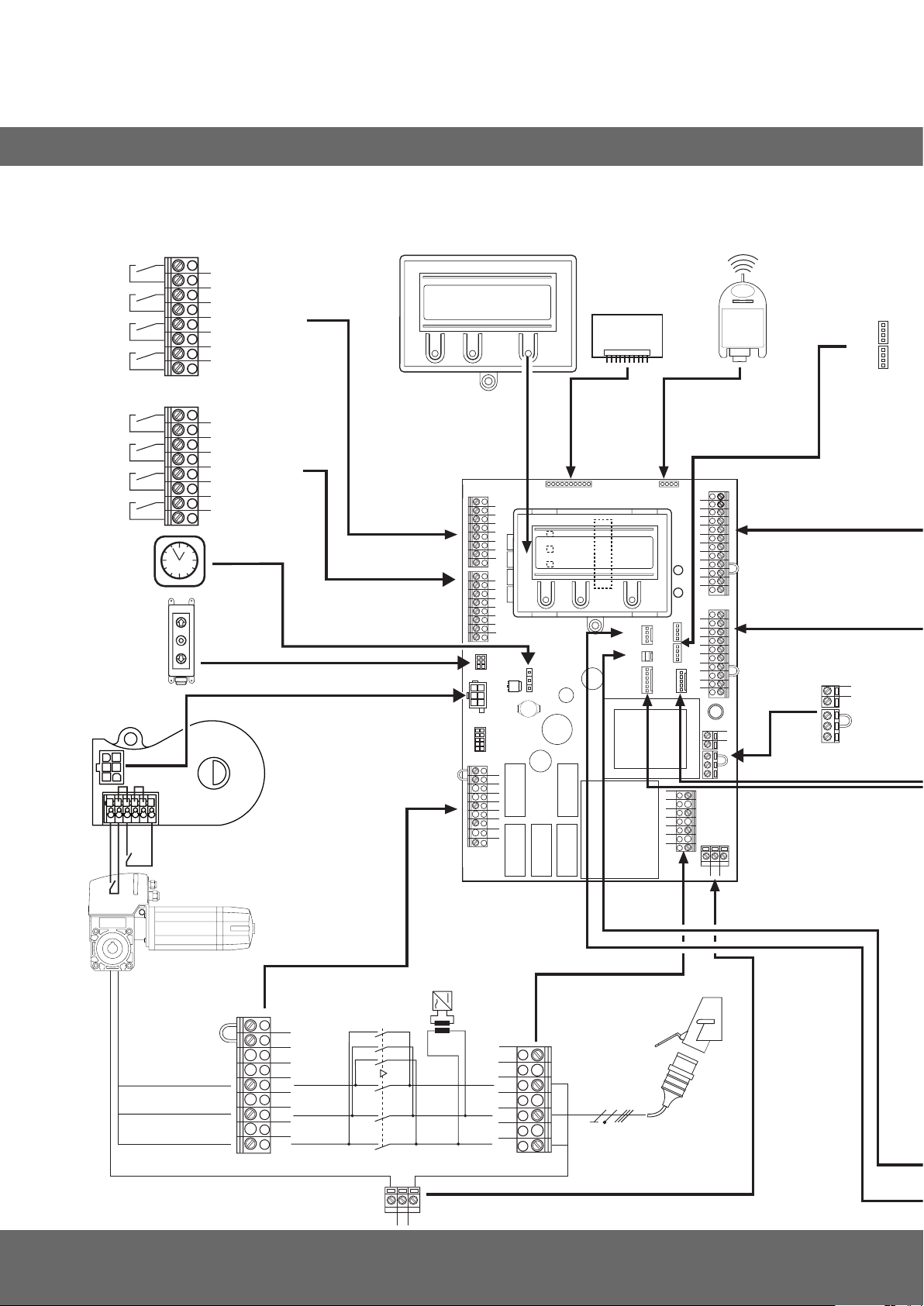
14. Appendix
14.1 Overview of connections
Terminal block X5
(potential-free switching contacts)
1
- relay 1
2
3
- relay 2
4
5
- relay 3
6
7
- relay 4
8
Terminal block X15
(mechanical limit switch)
1
- ES-OPEN
2
3
- ES-CLOSE
4
5
- BES-OPEN
6
7
- BES-CLOSE
8
X10
X11
X8
MSBUS
X17
X16
X5
1
2
3
4
5
6
7
8
1
2
3
4
5
6
7
X15
8
X14
X11
X18
B1
B2
W
V
U
X2
X10
X20
S1
S2
X8
S3
X12
X6
X9
X17
X16
X7
X13
N
L3
L2
L1
X4
12
11
10
9
8
7
6
5
4
3
H4
2
1
X3
H6
10
9
8
7
6
5
4
3
2
1
X19
X1
L
N
PEPEPE
F1
Terminal block X19
(Power supply connection
for external units)
L
N
X2
B2
B1
W
V
U
34 – CS 310 Gate Controls / Rev.B 1.0
K2
13 5135
K1
24 6246
PEPEPE
T1
X1
N
L3
400V/50Hz/3/N/PE
L2
L1
Page 71
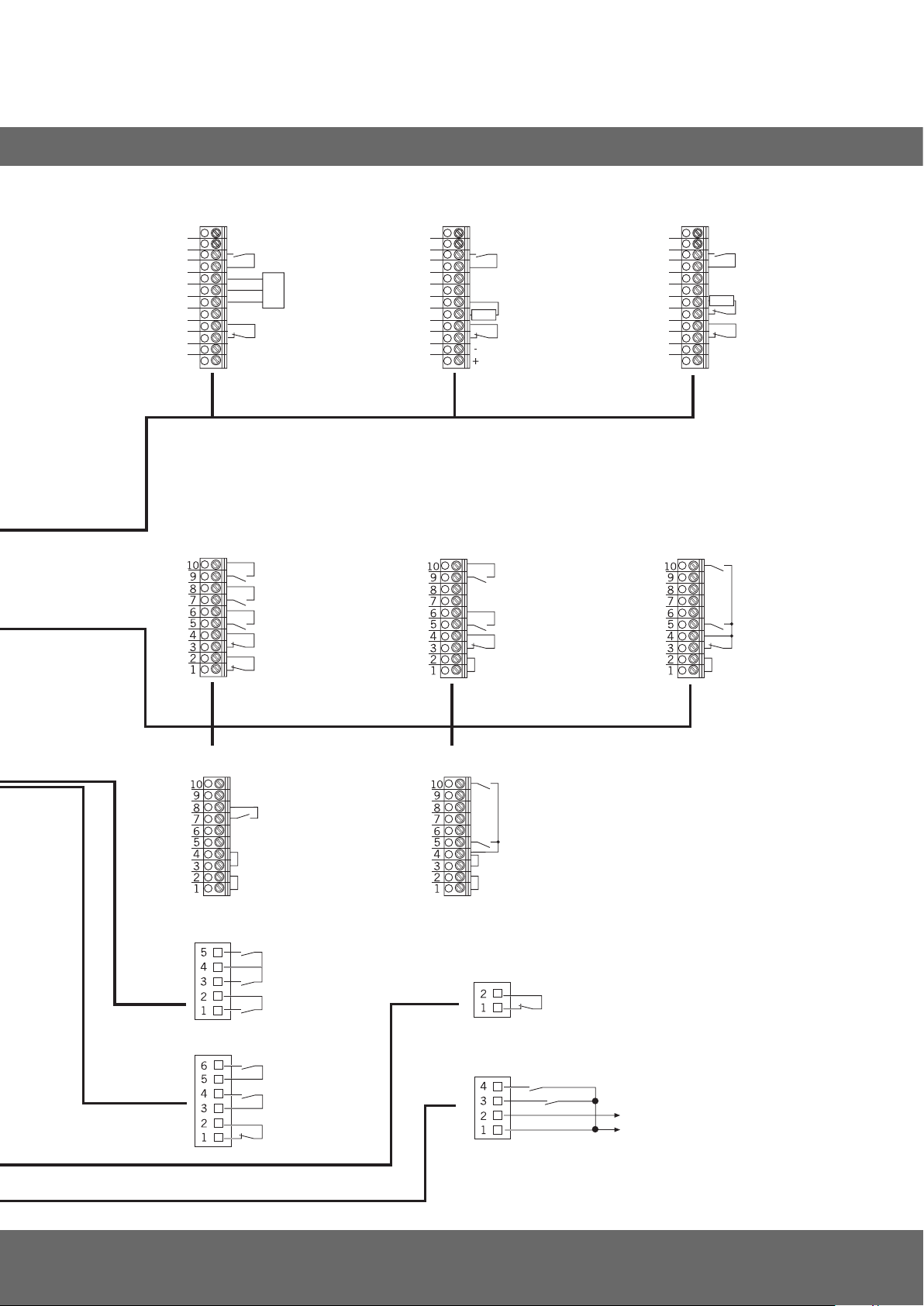
GB
X4
X3
Terminal block X4
(for opto-electronic closing edge safety device)
12
11
10
9
8
7
6
5
4
3
-
2
+
1
Terminal block X3
(assignment)
- SECT.-SWITCH
0V
- safety edge protection
Sig
OPTO
+ 12 V
- photoelectric
drive-through
- 24 V DC / 250 mA
- DOWN-SWITCH
- IMPULSE button1
2
3
- UP-SWITCH
- STOP
- emergency off, slack
rope switch, wicket
door contact, draw
in protection
Terminal block X4
( for 8.2 kOhm safety edge protection)
12
11
10
9
8
7
6
5
4
3
4
2
1
UP-SWITCH / STOP / DOWN-SWITCH
(6-lead solution)
- SECT.-SWITCH
- safety edge protection
8,2 KOhm
- photoelectric drive-through
- 24 V DC / 250 mA
- DOWN-SWITCH
2
3
4
- UP-SWITCH
- STOP
Terminal block X4
(for pneumatic safety edge protection - SCS TEST
12
11
10
9
8
7
6
5
4
3
2
+
1
UP-SWITCH / STOP / DOWN-SWITCH
(4-lead solution)
- SECT.-SWITCH
8,2 KOhm
- safety edge protection
- photoelectric drive-through
-
- 24 V DC / 250 mA
- DOWN-SWITCH
2
4
- UP-SWITCH
- DOWN-SWITCH
5
3
X13
X7
Impulse button
(sequence control)
CS switch
KDT switch
- IMPULSE button
- DOWN-SWITCH
- UP-SWITCH
- STOP
- DOWN-SWITCH
- UP-SWITCH
- STOP
Key switch UP / DOWN
- DOWN
- UP
Internal ON/OFF switch
X6
External radio
X12
- IMPULS button
- UP-SWITCH
- GND
- 24 V DC
1
sequence control
2
button or 2-way switch
3
effective in down direction
4
for external switching devices
(connection to terminals 1 and 2)
5
- An 8.2 KOhm resistor must be
connected in series
- The input parameter SCS TEST must
be switched on
wt: white
gr: green
br: brown
CS 310 Gate Controls / Rev.B 1.0 – 35
Page 72

#1700016725
#105030
 Loading...