


NLI
Installation and operating instructions
Radio Code Keypad
Instrucciones de montaje y de empleo
Pulsador de presión interior por radio
Istruzioni di uso e programmazione
Radio-tastiera interna
Command 131
GBE
I
English / Page 2
1. Contents
1. Contents .............................................................
2. Meaning of symbols............................................
3. Important safety advice.......................................
4. Installation ..........................................................
5. Learn coding .......................................................
6. Change coding ...................................................
Page 2
Page 2
Page 3
Page 4 - 5
Page 6 - 7
Page 8 - 9
Meaning of symbols:
Caution! Danger of personal injuries!
Attention: Danger of material damage!
2. Meaning of symbols
Advice / Tip!
3. Important safety advice
English / Page 3
GBGBFNLI
Installation and initial operation of this control unit may only be carried out by
qualified and trained specialist personnel. Qualified and trained specialist
personnel in the sense of this description are persons who have been trained
and are supervised sufficiently by electricians and therefore are able to recognize
the special hazards arising from electricity. Moreover they need to have the
following qualifications corresponding to the respective work to be done,
especially:
- Knowledge of the relevant electro-technical regulations,
- Training in use and maintenance of necessary safety equipment.
• Observe local safety regulations!
• Always lay mains and control cables separately!
Control voltage 24 V DC.
Caution!
In case these warnings are ignored, personal injuries and material
damages may occur.
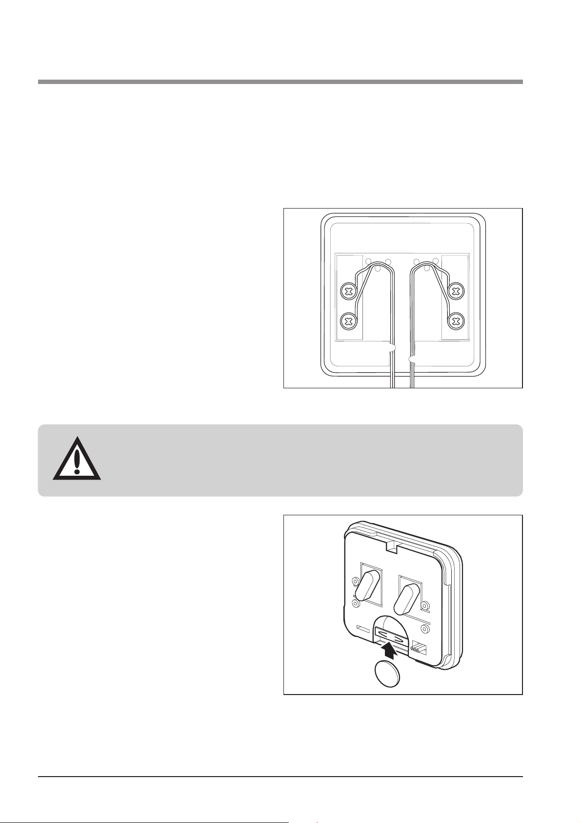
Step 2
• Insert the battery. Observe right
poling. Battery type 3 V, e.g.
CR2032.
Step 3
• Carry out the coding of the radio
interior keypad, as described in
'Learn coding'.
English / Page 4
4. Installation
Attention!
The connection cable may only be max. 3 m long.
Before you install the radio interior keypad, please
• remove the front and back covers from housing
• insert the battery
• carry out coding and
• connect possibly existing external buttons.
Step 1
• If there are external buttons, e.g. key
switches, screw the connecting
cables leading to these buttons to
the connections on the back of the
radio interior keypad.
Fig. 1: Connect external buttons
Fig. 2. Insert batteries
+
+
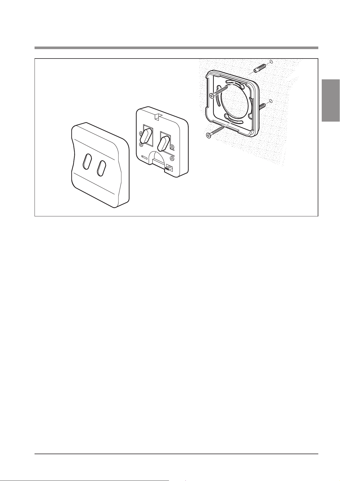
Step 4
• Mount the radio interior keypad without torsion to a suitable place as shown
in the picture.
4. Installation
English / Page 5
GBGBFNLI
Fig. 3: Installation
English / Page 6
5. Learn coding
To achieve the same function to be carried out with different transmitters, there
has to be a uniform coding of the transmitters. The example shows the
transmission of the coding from an already existing hand transmitter to the
radio interior keypad.
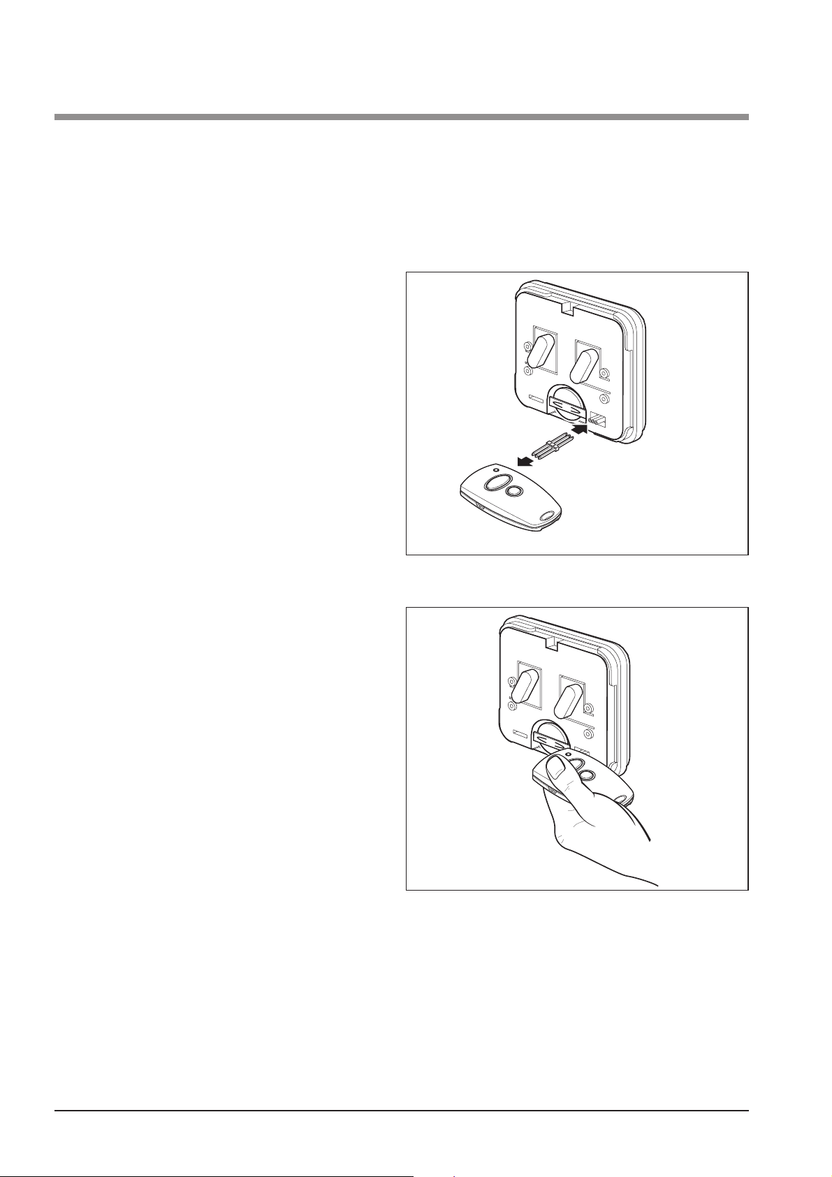
Step 1
• Connect the radio interior keypad
and the hand transmitter via the
enclosed programming plug.
Step 2
• Actuate the button on the hand
transmitter, the coding of which shall
be transmitted, and hold this button.
The LED on the hand transmitter is
on.
Fig. 4: Learn coding - 1
Fig. 5: Learn coding - 2
+
+
+
+
5. Learn coding
English / Page 7
GBGBFNLI
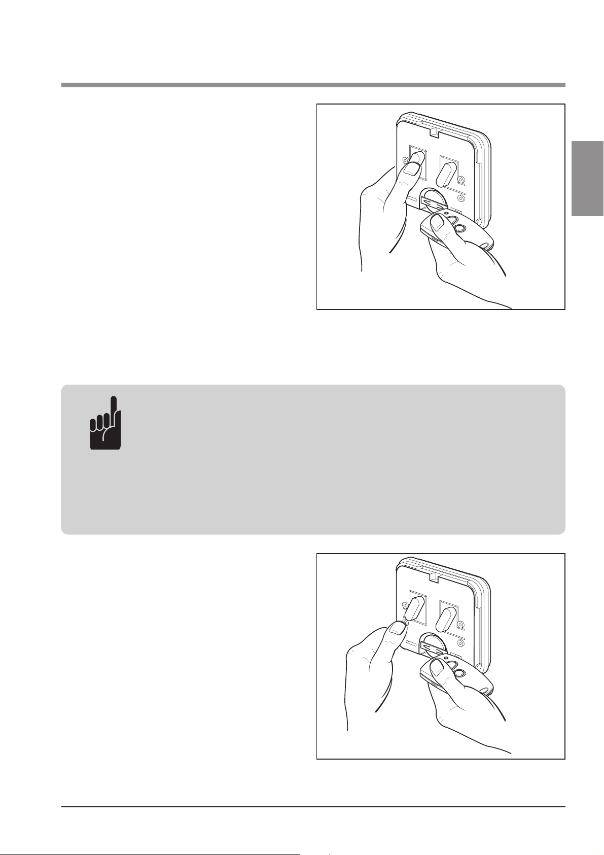
Step 3
• Actuate the button on the radio
interior keypad that is to learn the
coding, while you are still holding
the button on the hand transmitter.
The LED on the radio interior keypad
is flashing quickly.
After 1 - 2 sec. the LED on the radio
interior keypad is glowing constantly.
The programming of this channel is
terminated.
• Release both the button on the hand transmitter and on the radio interior
keypad.
Fig. 6: Learn coding - 3
Advice!
This procedure has to be carried out for each of the two buttons
separately, in case there are two garage door operators or
receivers. The transmission of the coding can also be made the
other way round (step 3), if you press first the button on the
radio interior keypad and hold it. In this case the hand transmitter
learns from the radio interior keypad.
Step 4
You can connect external buttons to
the radio interior keypad via cables. In
order to carry out the same function
with these as with the main buttons,
repeat steps 2 and 3.
But press for this the programming
buttons (P1, P2) on the radio interior
keypad, which are below the main
buttons in the housing.
Fig. 7: Learn coding - 4
+
+
+
+
English / Page 8
6. Change coding
This function makes it possible for the system to learn a new code in case a
hand transmitter has been lost. The example shows the change of the code on
the radio interior keypad. But the appropriate procedure would be to change the
code on a hand transmitter and to transmit this then to the radio interior keypad
(see “Learn coding”).
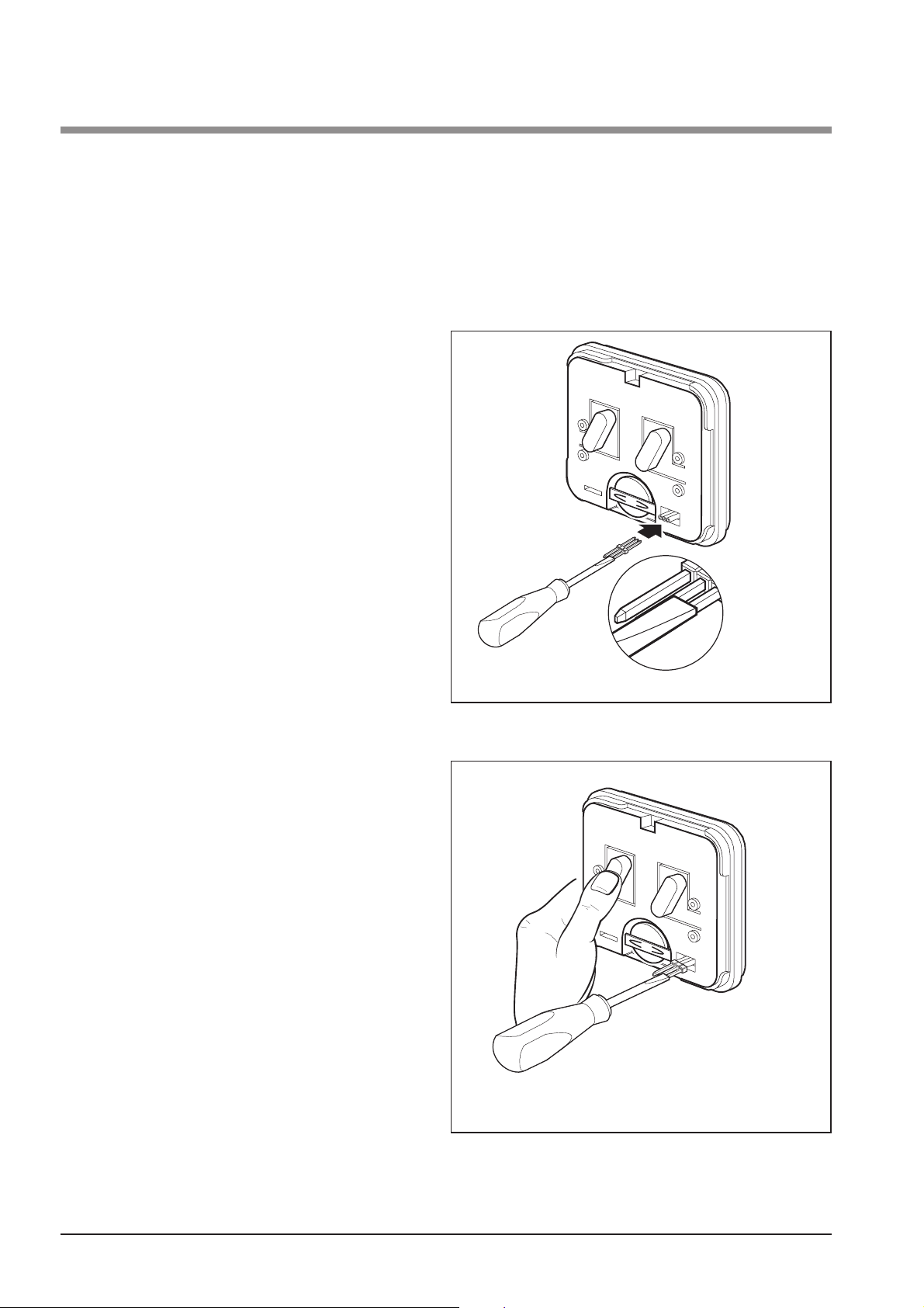
Step 1
• Connect the programming cable
to the radio interior keypad to be
re-programmed.
Step 2
• Short-circuit one of the two exterior
cables of the programming cable
with the centre cable.
Step 3
• Actuate one button on the radio
interior keypad.
The transmitter creates by means of
a random program a new code for
this button. During this time period
the LED is flashing quickly. After the
LED of the radio interior keypad is
on constantly, the button can be
released.
Fig. 8: Change coding - 1+2
Fig. 9: Change coding - 3
+
+
+
+

6. Change coding
English / Page 9
GBGBFNLI
Advice!
This procedure has to be carried out for all buttons separately.
Step 4
Change the code of the external
button.
For this repeat this procedure, but
press the buttons (P1, P2), that are
below the large button in the housing.
Fig. 10: Change coding - 4
Attention!
After the radio interior keypad has been re-programmed, the
controlled operator system has to be re-programmed as well with
the new coding, because the old coding is lost irreversibly (see
installation instructions of your garage door operator).
+
+
 Loading...