

Marantec Comfort 211 Operating Instrictions

FULL-SERVICE
ANTRIEBSSYSTEME
FÜR GARAGENTORE
ANTRIEBSSYSTEME
FÜR SEKTIONALTORE
ANTRIEBSSYSTEME
F
ÜR SCHIEBETORE
ANTRIEBSSYSTEME
FÜR DREHTORE
ANTRIEBSSYSTEME
FÜR ROLLTORE
PARKSCHRANKEN
SYSTEME
ELEKTRONISCHE
STEUERUNGEN
PRODUKT-SERVICE
ZUBEHÖR
Comfort 211
O
perator system for Garage Doors
GB
Manual for installation and operation
FULL-SERVICE
OPERATOR SYSTEMS
FOR GARAGE DOORS
OPERATOR SYSTEMS
FOR SECTIONAL DOORS
OPERATOR SYSTEMS
F
OR SLIDING GATES
OPERATOR SYSTEMS
FOR HINGED GATES
OPERATOR SYSTEMS
FOR ROLLER SHUTTERS
PARK BARRIER
SYSTEMS
ELECTRONIC
CONTROL UNITS
PRODUCT SERVICE
ACCESSORIES
2 Manual for installation and operation, Comfort 211 GB (#79105)
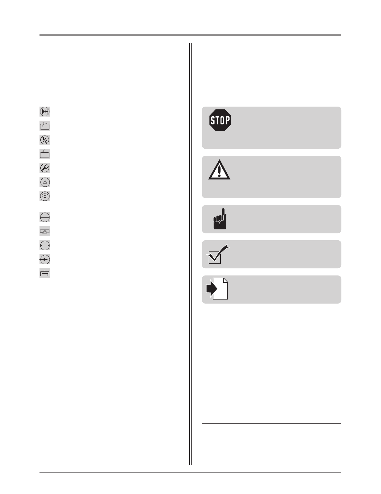
1. Meaning of symbols
Caution!
Danger of personal injury!
The following safety advice must
be observed at all times so as to avoid
personal injury!
Attention!
Danger of material damage!
The following safety advice must
be observed at all times so as to avoid
material damage!
Advice / Tip
Check
Reference
i
P
hotocell
Door position OPEN
Has no function
Door position CLOSED
Reference control point
Has no function
Impulse
(remote control, external control elements)
Operation
Closing edge safety device
STOP
External control elements
Modular antenna
Controls and motor unit symbols Advice
Type plate
Type: ________________________________________________
Art. No.: _____________________________________________
Product No.: __________________________________________

Manual for installation and operation, Comfort 211 GB (#79105) 3
2. Table of contents
1. Meaning of symbols . . . . . . . . . . . . . . . . . . . . . . . . . . . . . . . . . . . . . . . . . . . . . . . . . . . . . . . . . . . . . . . . . . . .2
2. Table of contents . . . . . . . . . . . . . . . . . . . . . . . . . . . . . . . . . . . . . . . . . . . . . . . . . . . . . . . . . . . . . . . . . . . . . . .3
3. General safety advice . . . . . . . . . . . . . . . . . . . . . . . . . . . . . . . . . . . . . . . . . . . . . . . . . . . . . . . . . . . . . . . . . . .4
4. Product overview . . . . . . . . . . . . . . . . . . . . . . . . . . . . . . . . . . . . . . . . . . . . . . . . . . . . . . . . . . . . . . . . . . . . . . .6
4.1 Comfort 211 supply package . . . . . . . . . . . . . . . . . . . . . . . . . . . . . . . . . . . . . . . . . . . . . . . . . . . . . . . . . .6
4.2 Door variations . . . . . . . . . . . . . . . . . . . . . . . . . . . . . . . . . . . . . . . . . . . . . . . . . . . . . . . . . . . . . . . . . . . . .7
5. Preparation for mounting . . . . . . . . . . . . . . . . . . . . . . . . . . . . . . . . . . . . . . . . . . . . . . . . . . . . . . . . . . . . . . . .8
5.1 General notes . . . . . . . . . . . . . . . . . . . . . . . . . . . . . . . . . . . . . . . . . . . . . . . . . . . . . . . . . . . . . . . . . . . . . .8
5.2 Checks . . . . . . . . . . . . . . . . . . . . . . . . . . . . . . . . . . . . . . . . . . . . . . . . . . . . . . . . . . . . . . . . . . . . . . . . . . .8
6. Installation . . . . . . . . . . . . . . . . . . . . . . . . . . . . . . . . . . . . . . . . . . . . . . . . . . . . . . . . . . . . . . . . . . . . . . . . . . . .9
6.1 Preparing the drive boom . . . . . . . . . . . . . . . . . . . . . . . . . . . . . . . . . . . . . . . . . . . . . . . . . . . . . . . . . . . .9
6.2 Installing the motor unit and drive boom . . . . . . . . . . . . . . . . . . . . . . . . . . . . . . . . . . . . . . . . . . . . . . . .11
6.3 Installation on swing-out retractable up-and-over doors . . . . . . . . . . . . . . . . . . . . . . . . . . . . . . . . . . . . .12
6.4 Installation on sectional doors . . . . . . . . . . . . . . . . . . . . . . . . . . . . . . . . . . . . . . . . . . . . . . . . . . . . . . . .14
6.5 Ceiling installation of the operator system . . . . . . . . . . . . . . . . . . . . . . . . . . . . . . . . . . . . . . . . . . . . . . .16
6.6 Release . . . . . . . . . . . . . . . . . . . . . . . . . . . . . . . . . . . . . . . . . . . . . . . . . . . . . . . . . . . . . . . . . . . . . . . . . .17
6.7 Connection of control elements . . . . . . . . . . . . . . . . . . . . . . . . . . . . . . . . . . . . . . . . . . . . . . . . . . . . . .18
7. Hand transmitter . . . . . . . . . . . . . . . . . . . . . . . . . . . . . . . . . . . . . . . . . . . . . . . . . . . . . . . . . . . . . . . . . . . . . .19
7.1 Operation and accessories . . . . . . . . . . . . . . . . . . . . . . . . . . . . . . . . . . . . . . . . . . . . . . . . . . . . . . . . . . .19
7.2 Hand transmitter coding . . . . . . . . . . . . . . . . . . . . . . . . . . . . . . . . . . . . . . . . . . . . . . . . . . . . . . . . . . . .20
8. Initial operation . . . . . . . . . . . . . . . . . . . . . . . . . . . . . . . . . . . . . . . . . . . . . . . . . . . . . . . . . . . . . . . . . . . . . . .22
8.1 Connecting the operator system . . . . . . . . . . . . . . . . . . . . . . . . . . . . . . . . . . . . . . . . . . . . . . . . . . . . . .22
8.2 Overview of the control unit . . . . . . . . . . . . . . . . . . . . . . . . . . . . . . . . . . . . . . . . . . . . . . . . . . . . . . . . . .22
8.3 Overview of the display functions . . . . . . . . . . . . . . . . . . . . . . . . . . . . . . . . . . . . . . . . . . . . . . . . . . . . . .23
8.4 Reference point . . . . . . . . . . . . . . . . . . . . . . . . . . . . . . . . . . . . . . . . . . . . . . . . . . . . . . . . . . . . . . . . . . .23
8.5 Express programming . . . . . . . . . . . . . . . . . . . . . . . . . . . . . . . . . . . . . . . . . . . . . . . . . . . . . . . . . . . . . . .24
8.6 Function test . . . . . . . . . . . . . . . . . . . . . . . . . . . . . . . . . . . . . . . . . . . . . . . . . . . . . . . . . . . . . . . . . . . . .26
9. Extended operator functions . . . . . . . . . . . . . . . . . . . . . . . . . . . . . . . . . . . . . . . . . . . . . . . . . . . . . . . . . . . .27
9.1 General notes on extended operator functions . . . . . . . . . . . . . . . . . . . . . . . . . . . . . . . . . . . . . . . . . . . .27
9.2 Programming structure for extended operator functions (Example for Level 2, Menu 2) . . . . . . . . . . . . .28
9.3 General overview of the programmable functions . . . . . . . . . . . . . . . . . . . . . . . . . . . . . . . . . . . . . . . . .29
9.4 Functions overview for the levels . . . . . . . . . . . . . . . . . . . . . . . . . . . . . . . . . . . . . . . . . . . . . . . . . . . . . .30
10. Messages . . . . . . . . . . . . . . . . . . . . . . . . . . . . . . . . . . . . . . . . . . . . . . . . . . . . . . . . . . . . . . . . . . . . . . . . . . . .33
10.1 Status messages . . . . . . . . . . . . . . . . . . . . . . . . . . . . . . . . . . . . . . . . . . . . . . . . . . . . . . . . . . . . . . . . . .33
10.2 Fault messages . . . . . . . . . . . . . . . . . . . . . . . . . . . . . . . . . . . . . . . . . . . . . . . . . . . . . . . . . . . . . . . . . . . .33
10.3 Rectifying faults . . . . . . . . . . . . . . . . . . . . . . . . . . . . . . . . . . . . . . . . . . . . . . . . . . . . . . . . . . . . . . . . . . .35
11. Attachment . . . . . . . . . . . . . . . . . . . . . . . . . . . . . . . . . . . . . . . . . . . . . . . . . . . . . . . . . . . . . . . . . . . . . . . . . .38
11.1 Comfort 211 replacement parts overview . . . . . . . . . . . . . . . . . . . . . . . . . . . . . . . . . . . . . . . . . . . . . . . .38
11.2 Technical Data for Comfort 211 . . . . . . . . . . . . . . . . . . . . . . . . . . . . . . . . . . . . . . . . . . . . . . . . . . . . . . .40
11.3 Manufacturer’s Declaration . . . . . . . . . . . . . . . . . . . . . . . . . . . . . . . . . . . . . . . . . . . . . . . . . . . . . . . . . . .41
11.4 EC Declaration of Conformity . . . . . . . . . . . . . . . . . . . . . . . . . . . . . . . . . . . . . . . . . . . . . . . . . . . . . . . . .41

4 Manual for installation and operation, Comfort 211 GB (#79105)
Please read carefully!
Target group
This operator system may only be installed, connected and put into operation by qualified and trained professionals!
Q
ualified and trained specialist personnel are persons
- who have knowledge of the general and special safety regulations,
- who have knowledge of the relevant electro-technical regulations,
- with training in the use and maintenance of suitable safety equipment,
- who are sufficiently trained and supervised by qualified electricians,
- who are able to recognise the particular hazards involved when working with electricity,
- with knowledge regarding applications of the EN 12635 standard (installation and usage requirements).
Warranty
For an operations and safety warranty, the advice in this instruction manual has to be observed. Disregarding these
warnings may lead to personal injury or material damage. If this advice is disregarded, the manufacturer will not be liable for damages that might occur.
Batteries, fuses and bulbs are excluded from warranty.
To avoid installation errors and damage to the door and operator system, it is imperative that the installation
instructions are followed. The system may only be used after thoroughly reading the respective mounting and
installation instructions.
The installation and operating instructions are to be given to the door system user, who must keep them safe.
They contain important advice for operation, checks and maintenance.
This item is produced according to the directives and standards mentioned in the Manufacturer's Declaration and in
the Declaration of Conformity. The product has left the factory in perfect condition with regard to safety.
Power-operated windows, doors and gates must be checked by an expert (and this must be documented) before they
are put into operation and thereafter as required, but at least once a year.
Correct use
The operator system is designed exclusively for opening and closing garage doors.
The operator must be used in a dry place.
The maximum push and pull force must be observed.
Door requirements
The operator system is suitable for:
- small and medium garage doors up to a door weight of 75 kg
(this corresponds approximately to a door size of 3000 mm x 2250 mm with a weight of approx. 11 - 15 kg/sqm).
The door must:
- stand still alone (by balance of springs),
- run smoothly.
Beside the advice in these instructions, please observe the general safety and accident prevention regulations!
Our sales and supply terms and conditions are effective.
3. General safety advice

Manual for installation and operation, Comfort 211 GB (#79105) 5
Information on installing the operator system
• Ensure that the door is in good mechanical condition.
•
Ensure that the door can stop in any position.
• Ensure that the door can be easily moved in the OPEN and CLOSE directions.
• Ensure that the door opens and closes properly.
• Remove all unnecessary components from the door (e.g. cables, chains, brackets).
• Render any installations inoperable that will no longer be needed after the operator system has been installed.
• Before commencing cabling works it is very important to disconnect the operator system from the electricity supply.
Ensure that the electricity supply remains disconnected throughout the cabling works.
• Adhere to the local protection regulations.
• Lay the electricity supply cables and control cables; these MUST be laid separately. The controls voltage is 24 V DC.
• Install the operator system with the door in the CLOSED position.
• Install all the impulse transmitters and control devices (e.g. remote control buttons) within sight of the door and at a
safe distance from the moving parts of the door. A minimum installation height of 1.5 m must be observed.
• Permanently fix the warning signs, which advise of the danger of becoming trapped, at conspicuous locations.
• Ensure that no part of the door extends across public footways or roads when the installation is complete.
Information on commissioning the operator system
After initial operation, the persons responsible for operating the door system, or their representatives must be
familiarised with the use of the system.
• Make sure that children cannot access the door control unit.
• Before moving the door, make sure that there are neither persons nor objects in the operating range of the door.
• Test all existing emergency command devices.
• Never insert your hands into a running door or moving parts.
• Pay attention to any parts of the gate system that could cause crushing or shearing damage or accidents.
The EN 13241-1 regulations must be observed.
Information on servicing the operator system
To ensure proper operation, the following items must be checked regularly and repaired if necessary.
Before any works to the door system are undertaken, the operator system must be disconnected from the mains.
• Check once a month to ensure that the operator system reverses if the door encounters an obstacle.
Depending on the operational direction of the door, place a 50 mm high/wide obstacle in its path.
• Check the settings of the OPEN and CLOSE automatic cut-out function.
• Check all movable parts of the door and operator system.
• Check the door system for signs of wear or damage.
• Check whether the door can be easily moved by hand.
Information on cleaning the operator system
Never use water jets, high pressure cleaners, acids or bases for cleaning.
Please read carefully!
3. General safety advice
6 Manual for installation and operation, Comfort 211 GB (#79105)
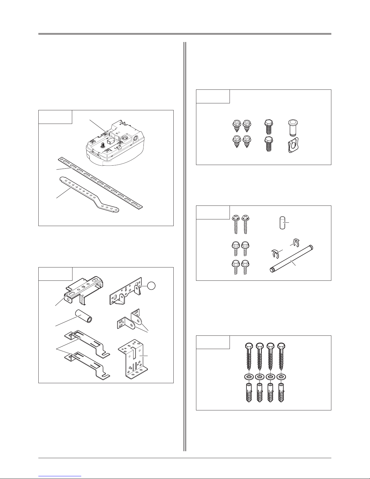
4.1 Comfort 211 supply package
4. Product overview
1 Comfort 211 motor unit
2 Support plate
3 Door link
4.1 / 1
4.1 / 4
4.1 / 5
4.1 / 3
1
!#
!£
!^
!
5
!\
!˜
!·
„¯
2
3
!¯ !Ø !”
4 Support clip
5 Lintel joining plate
6 Securing sleeve
7 Door link (2x)
8 Boom clamps (2x)
9 Door connector
10 Self-tapping screws 6.3 x 16 (4x)
11 Hexagonal head screws M6 x 20 (2x)
12 A8 bolts with SL securing clip
13 Screws 4.0 x 18 (2x)
14 Screws 6.0 x 14 (4x)
15 Bolts 8 x 20
16 Securing clips (2x)
17 Hinge pins ø 6
18 Screws 8.0 x 70 (4x)
19 A8 U-plate (4x)
20 U10 wall plugs (4x)
Standard package
4
6
7
8
9
4.1 / 2
5
Manual for installation and operation, Comfort 211 GB (#79105) 7
4. Product overview
4.1 / 6
„”
„£
„5
„#
„·
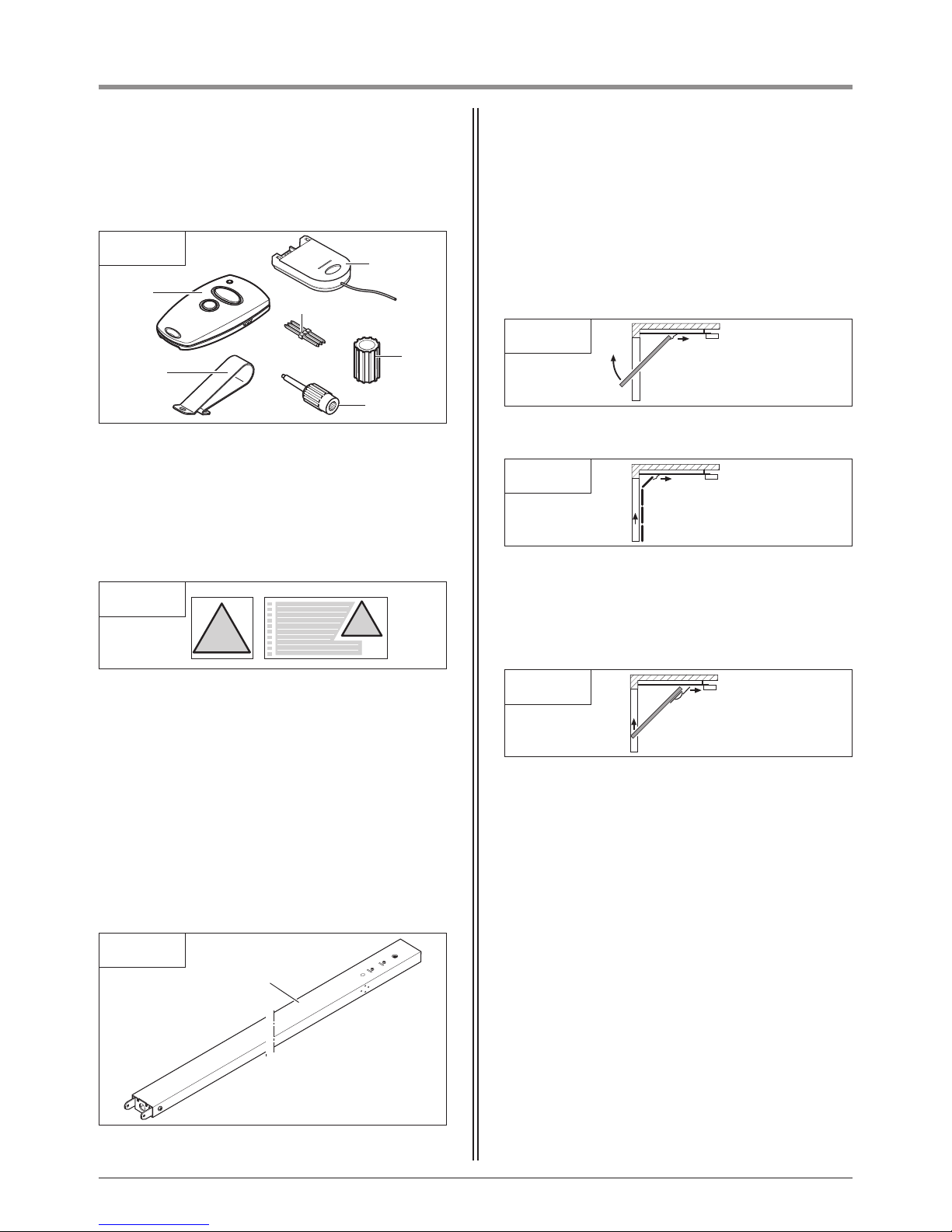
4.2 Door variations
4.2 / 1
The standard package with the appropriate operator
boom is suitable for the following types of door.
Swing out retractable up-and-over door
4.2 / 2
Sectional door
„^
Non-swing out retractable up-and-over door
4.2 / 3
4.1 / 8
„∏
21 Hand transmitter
22 Sun visor clip
23 Modular antenna
24 Transmission plug
25 Adapter sleeve
26 Programming pin
29 Drive boom
4.1 / 7
„˜„\
27 Release warning sign
28 Warning stickers
In addition to the components included in the standard
package, the following accessories are required for the
installation:
- drive boom
Drive booms
The motor unit can be combined with various types of
drive boom.
Special accessories are necessary for the following door
type.

8 Manual for installation and operation, Comfort 211 GB (#79105)
5.2 Checks
Attention!
In order to guarantee correct mounting,
carry out the following checks before
installing.
Supply package
• Check the package to ensure that all the parts are
included.
• Check that you have all the additional components
that are necessary for your particular installation
requirements.
Garage
• Check whether your garage has a suitable mains
connection and a mains disconnection facility.
Door system
5. Preparation for mounting
5.1 General notes
The pictures in these instructions are not true-to-scale.
Dimensions are always given in millimetres (mm)!
For correct mounting you will need the following
tools:
5.1 / 1
10 13 10
13 2 ø 10 ø 5
ø 5
Attention!
For garages without a second entrance:
the garage door must be fitted with an
emergency release system to allow
access to the garage if a fault occurs.
If a release kit is used:
• Check that the door locks are functioning correctly.
The door locks may not be disabled under any
circumstances.
If a release kit is not used:
• Dismantle or disable the door locks.
• Check that the door to be operated fulfils the
following conditions:
- the door must be easily moveable by hand,
- the door should automatically remain in every
position into which it was moved.
Reference:
When using and installing accessories,
always observe the specific instructions
included with the equipment.
i

Manual for installation and operation, Comfort 211 GB (#79105) 9
6. Installation
6.1 / 1
6.1 / 2
6.1 Preparing the drive boom
• Press the red release pin (A) as far as possible into
the red opening on the carriage.
• Pull the pull cord (B) to release the carriage.
The carriage is now unlocked and can move freely in
the drive boom.
A
A
Reference:
The release function for the carriage
is described in Section 6.6.
i
• Remove the red release pin (A).
• Insert the door link (C) using the bolt (D) into the
carriage.
• Screw the bolt down (D) with two screws.
C
D
6.1 / 3
4 x 18
Reference:
When using multi-component booms,
refer to the corresponding instruction
manual.
i
6.1 / 4
• Slide the red securing sleeve (E) over the tension
straining screw (F).
EF
Advice:
The securing sleeve serves as protection
against unauthorized, forceful
dismantling (break-in) from outside.
B
10 Manual for installation and operation, Comfort 211 GB (#79105)
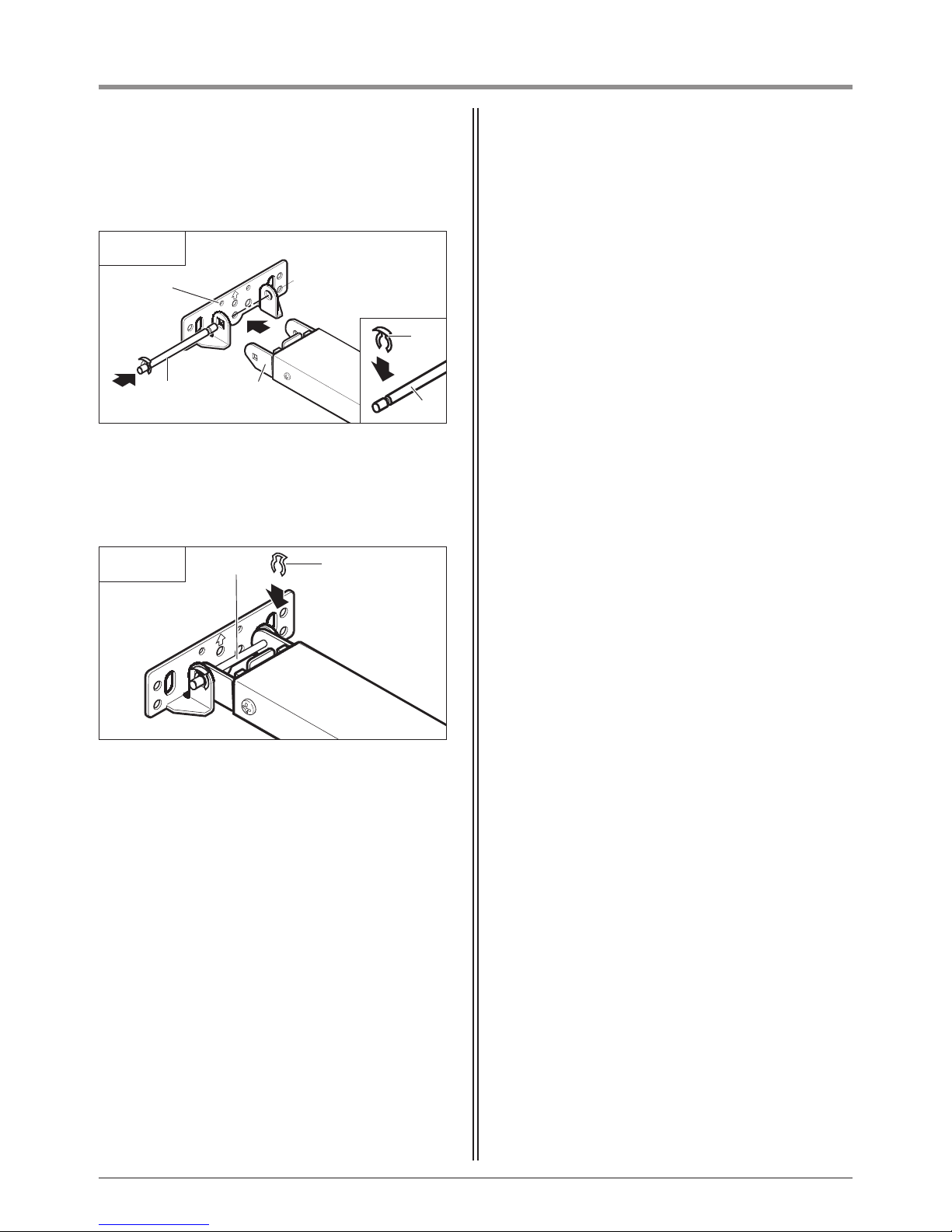
6. Installation
6.1 / 6
• Secure the pivot bolt (H) with an additional securing
clip (G).
G
H
6.1 / 5
• Push the securing clip (G) onto the pivot bolt (H).
• Connect the lintel joining plate (I) and the boom
end (J) to the pivot bolt (H).
I
G
H
H
J
Manual for installation and operation, Comfort 211 GB (#79105) 11
6. Installation
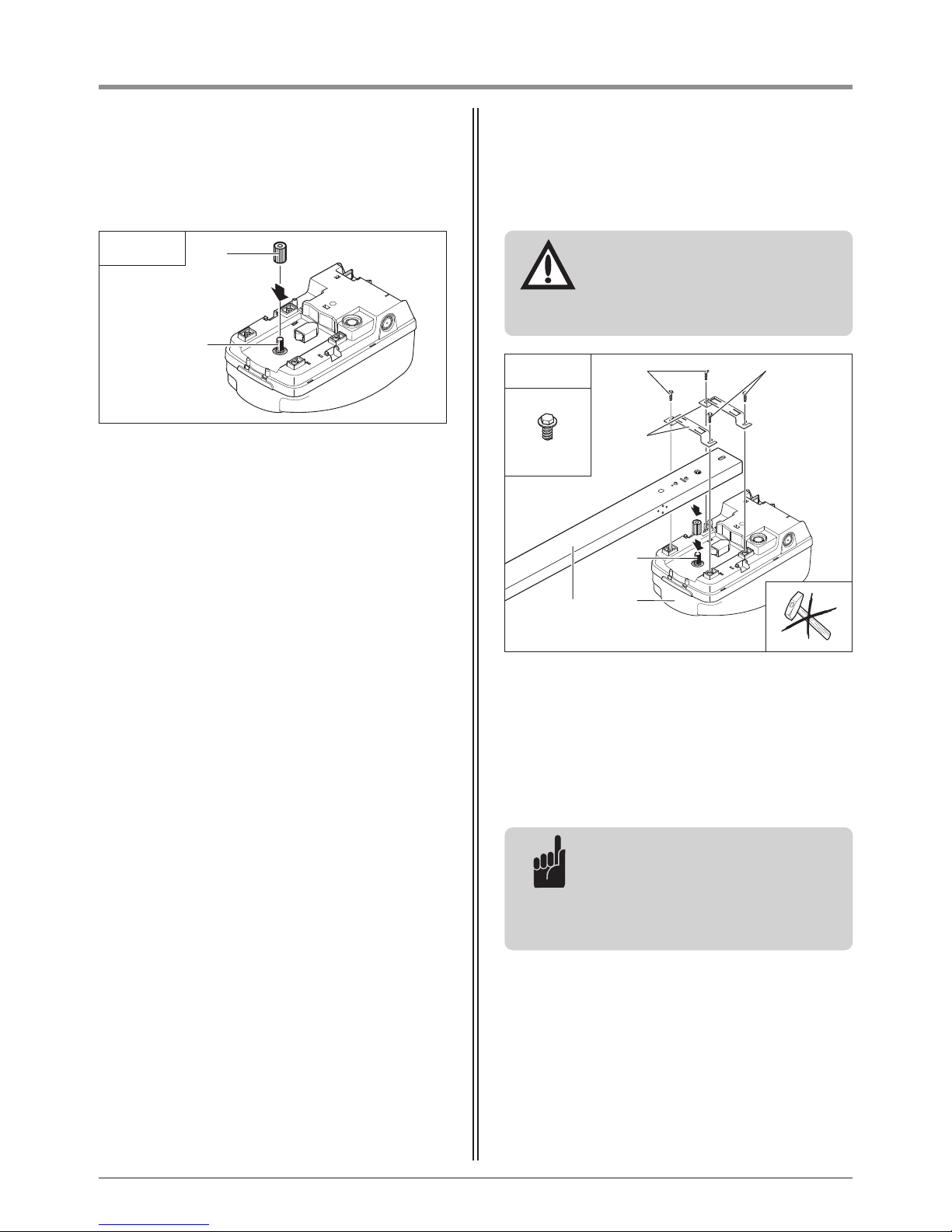
6.2 Installing the motor unit and drive
boom
• Push the adapter sleeve (A) onto the gear shaft (B) as
far as it will go.
6.2 / 1
• Align the drive boom (C) such that it runs parallel to
the surface of the motor unit (F).
• Place the drive boom (C) in the correct position on
the adapter sleeve (A).
• Applying slight pressure, lower the drive boom (C)
onto the motor unit (F).
Attention!
The drive boom (C) must be carefully
mounted on the motor unit (F).
Do not use force, as this could damage
the gear teeth!
A
B
A
F
C
D
E
E
6.2 / 2
6.0 x 14
Tip:
When the drive boom (C) is correctly
aligned, a short pull on the drive
element (chain drive, toothed drive belt
or ball chain) is sufficient to lower the
drive boom.
• Position the boom clamps (D) on the drive boom (C).
• Screw the boom clamps (D) to the motor unit (F)
using the four screws (E).
a
a
a
a
a
a
a
a
a
a
a
a
a
a
a
aa
a
a
a
a
a
a
a
a
a
a
a
a
a
a
a
aa
a
a
a
aaa
a
a
a
a
a
a
aa
a
a
a
a
a
a
a
a
a
aa
a
a
a
a
a
a
a
a
a
aa
a
a
a
a
a
a
a
a
aa
a
a
a
a
a
a
aa
a
a
aa
a
a
a
a
a
a
a
a
a
aa
aa
aa
a
a
a
a
a
a
a
a
a
a
aa
a
aa
a
a
aa
a
a
a
a
a
a
a
a
a
a
a
a
a
a
a
aa
aaa
a
a
a
a
a
a
a
a
a
a
a
a
a
a
a
aaa
a
a
aa
a
a
a
a
a
a
aa
aa
a
a
aa
a
aa
a
a
aa
a
a
a
a
a
a
a
a
a
a
aa
a
a
a
a
aa
a
aa
a
a
a
a
a
a
a
a
a
a
a
a
a
a
a
a
a
a
a
a
a
a
a
a
a
a
a
a
a
aa
a
a
a
a
a
a
a
a
a
a
a
a
a
a
aa
a
a
aaa
a
a
a
a
aa
a
a
a
a
a
a
a
aa
a
a
a
a
a
a
a
a
a
a
a
aa
a
a
aa
a
a
a
a
a
a
aa
a
a
a
a
a
a
a
a
a
a
a
a
a
a
a
a
a
a
a
a
a
a
a
a
a
a
a
aaaa
aa
a
a
a
a
a
aa
a
a
a
aa
a
a
a
a
a
a
a
a
a
a
aa
a
a
aa
a
aa
a
a
a
a
a
a
a
a
a
aa
a
a
a
a
a
a
a
a
a
a
a
aa
a
a
a
a
a
a
a
a
a
a
a
a
a
a
a
a
a
aa
a
a
a
aa
a
a
a
a
a
a
a
a
a
a
a
a
a
a
a
a
a
a
a
a
a
a
a
a
aa
a
a
a
a
a
a
a
a
a
a
a
a
a
a
a
12 Manual for installation and operation, Comfort 211 GB (#79105)
a
a
a
a
a
a
a
a
a
a
a
a
a
a
a
a
a
a
a
a
a
a
a
a
a
a
aa
a
a
a
a
a
a
a
a
a
a
aa
a
a
a
a
a
a
a
a
a
a
aaa
a
a
a
a
a
a
aa
a
a
a
aaa
a
a
a
a
a
a
aa
a
aa
a
a
a
a
a
a
a
a
a
a
a
aa
a
a
a
a
a
a
a
a
a
a
a
a
aa
aa
a
a
a
a
a
a
a
a
aa
a
a
a
a
a
a
aa
aa
a
a
a
a
aa
a
a
a
a
a
a
a
a
a
aa
aa
aa
a
a
aa
a
a
a
a
a
a
a
a
a
a
a
aa
a
aa
a
a
aa
a
a
a
a
a
a
aa
a
a
a
a
a
a
a
a
a
a
a
a
aa
aaa
a
a
a
a
a
a
a
a
a
a
a
a
a
a
a
a
a
a
a
a
aaa
a
a
aa
a
a
a
a
a
a
a
a
a
a
aa
aa
a
a
aa
a
aa
a
a
aa
a
a
a
a
a
a
a
a
a
a
a
a
a
a
a
aa
a
a
a
a
aa
a
aa
a
a
a
a
a
a
a
a
a
a
a
a
a
a
a
a
a
a
a
a
a
a
a
a
a
aa
a
a
a
a
a
a
a
a
a
a
a
aa
a
a
a
a
a
a
a
a
a
a
a
a
a
a
a
a
a
a
a
aa
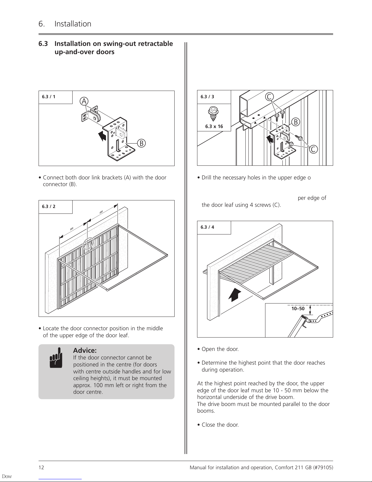
6.3 / 4
• Open the door.
• Determine the highest point that the door reaches
during operation.
At the highest point reached by the door, the upper
edge of the door leaf must be 10 - 50 mm below the
horizontal underside of the drive boom.
The drive boom must be mounted parallel to the door
booms.
• Close the door.
10–50
6. Installation
a
a
a
a
a
a
a
a
a
a
a
a
aa
a
a
a
a
a
a
a
a
a
a
a
a
a
a
a
a
a
a
aaa
a
a
a
a
a
a
a
a
a
a
a
aa
a
a
a
a
a
a
a
a
a
a
aa
a
a
a
a
a
a
a
a
a
a
a
aa
a
a
a
a
a
a
aa
a
a
a
aaa
a
a
a
a
a
a
aa
a
aa
a
a
a
a
a
a
a
a
a
a
a
aa
a
a
a
a
a
a
a
a
a
a
a
a
aa
aa
a
a
a
a
a
a
a
a
aa
a
a
a
a
a
a
aa
aa
a
a
a
a
aa
a
a
a
a
a
a
a
a
a
aa
aa
aa
a
a
aa
a
a
a
a
a
a
a
a
a
a
a
aa
a
aa
a
a
aa
a
a
a
a
a
a
aa
a
a
a
a
a
a
a
a
a
a
a
a
aa
aaa
a
a
a
a
a
a
a
a
a
a
a
a
a
a
a
a
a
a
a
a
aaa
a
a
aa
a
a
a
a
a
a
a
a
a
a
aa
aa
a
a
aa
a
aa
a
a
aa
a
a
a
a
a
a
a
a
a
a
a
a
a
a
a
aa
a
a
a
a
aa
a
aa
a
a
a
a
a
a
a
a
a
a
a
a
a
a
a
a
a
a
a
a
a
a
a
a
a
aa
a
a
a
a
a
a
a
a
a
a
a
aa
a
a
a
a
a
a
a
a
a
a
a
a
a
a
a
a
a
a
a
aa
a
a
aa
a
a
a
a
a
aa
a
a
a
a
a
a
a
a
a
a
a
aa
a
a
a
a
a
a
a
a
a
a
a
aa
a
6.3 Installation on swing-out retractable
up-and-over doors
• Connect both door link brackets (A) with the door
connector (B).
6.3 / 2
B
C
C
6.3 / 1
B
• Drill the necessary holes in the upper edge of the
door leaf (ø 5 mm).
• Screw the door connector (B) to the upper edge of
the door leaf using 4 screws (C).
A
• Locate the door connector position in the middle
of the upper edge of the door leaf.
Advice:
If the door connector cannot be
positioned in the centre (for doors
with centre outside handles and for low
ceiling heights), it must be mounted
approx. 100 mm left or right from the
door centre.
6.3 x 16
6.3 / 3
a
a
a
a
a
a
a
a
a
a
a
a
aa
a
a
a
a
a
a
a
a
a
a
a
a
a
a
a
a
a
a
aaa
a
a
a
a
a
a
a
a
a
a
a
aa
a
a
a
a
a
a
a
a
a
a
aa
a
a
a
a
a
a
a
a
a
a
a
aa
a
a
a
a
a
a
aa
a
a
a
aaa
a
a
a
a
a
a
aa
a
aa
a
a
a
a
a
a
a
a
a
a
a
aa
a
a
a
a
a
a
a
a
a
a
a
a
aa
aa
a
a
a
a
a
a
a
a
aa
a
a
a
a
a
a
aa
aa
a
a
a
a
aa
a
a
a
a
a
a
a
a
a
aa
aa
aa
a
a
aa
a
a
a
a
a
a
a
a
a
a
a
aa
a
aa
a
a
aa
a
a
a
a
a
a
aa
a
a
a
a
a
a
a
a
a
a
a
a
aa
aaa
a
a
a
a
a
a
a
a
a
a
a
a
a
a
a
a
a
a
a
a
aaa
a
a
aa
a
a
a
a
a
a
a
a
a
a
aa
aa
a
a
aa
a
aa
a
a
aa
a
a
a
a
a
a
a
a
a
a
a
a
a
a
a
aa
a
a
a
a
aa
a
aa
a
a
a
a
a
a
a
a
a
a
a
a
a
a
a
a
a
a
a
a
a
a
a
a
a
aa
a
a
a
a
a
a
a
a
a
a
a
aa
a
a
a
a
a
a
a
a
a
a
a
a
a
a
a
a
a
a
a
aa
a
a
aa
a
a
a
a
a
aa
a
a
a
a
a
a
a
a
a
a
a
aa
a
a
a
a
a
a
a
a
a
a
a
aa
a
Manual for installation and operation, Comfort 211 GB (#79105) 13
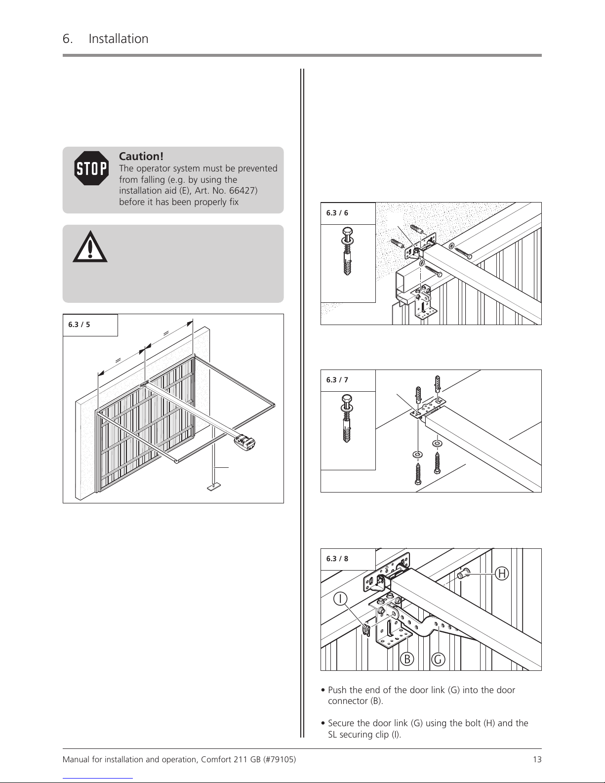
6.3 / 8
• Push the end of the door link (G) into the door
connector (B).
• Secure the door link (G) using the bolt (H) and the
SL securing clip (I).
G
H
I
B
6.3 / 6
6.3 / 7
6. Installation
6.3 / 5
Caution!
The operator system must be prevented
from falling (e.g. by using the
installation aid (E), Art. No. 66427)
before it has been properly fixed.
• Position the motor unit with the drive boom at the
mid point on the lintel above the door connector.
• Take measures to prevent the operator system from
falling before it has been properly fixed.
Depending on the site requirements, there are two
installation possibilities for the lintel joining plate (F):
Mounting to the lintel
Mounting to the ceiling
• Fix the lintel joining plate (F) as required for your type
of installation.
F
F
E
Attention!
To ensure perfect movement of the
door, the lintel joining plate for
the drive boom must be mounted at
the mid point, above the door
connector.
8.0 x 70
A8 / U10
8.0 x 70
A8 / U10
a
a
a
a
a
a
a
a
a
aaa
a
a
a
a
a
a
a
a
a
a
a
a
a
a
a
a
a
a
a
a
aa
a
a
a
a
a
a
a
a
a
a
aaa
a
a
a
aa
a
a
a
aaa
a
a
a
a
a
a
aa
a
aa
a
a
a
a
a
a
a
a
a
aa
a
a
a
a
a
a
a
a
a
a
a
a
aa
aa
a
a
a
a
a
aa
a
a
a
a
a
a
aa
aa
a
a
a
a
aa
a
a
a
a
a
a
aa
aa
aa
a
a
aa
a
a
a
a
a
a
a
a
a
a
a
aa
a
a
aa
a
a
a
a
a
a
aa
a
a
a
a
a
a
a
a
a
aa
aaa
a
a
a
a
a
a
a
a
a
a
a
a
a
a
a
a
a
a
a
a
a
aa
a
a
a
a
a
a
a
a
a
a
aa
aa
a
a
aa
a
a
aa
a
a
a
a
a
a
a
a
a
a
a
a
a
a
a
aa
a
a
a
a
aa
a
a
a
a
a
a
a
a
a
a
a
a
a
a
a
a
a
a
a
a
a
a
aa
a
a
a
a
a
a
a
a
a
a
a
aa
a
a
a
a
a
a
a
a
a
a
a
a
a
a
a
a
a
aa
a
a
aaa
a
a
a
a
aa
a
a
a
a
a
a
a
a
aa
a
a
a
a
a
a
a
a
a
a
a
aa
a
a
a
a
a
a
a
a
a
a
a
aa
a
a
a
a
a
a
a
a
a
a
a
a
a
a
a
a
a
a
a
a
a
a
a
a
a
a
a
a
a
aaaa
a
a
a
a
aa
a
a
aa
a
a
a
aa
a
a
a
a
a
a
a
a
a
a
aa
a
a
a
a
aa
a
aa
a
a
a
a
a
a
a
a
a
a
a
a
a
aa
a
a
a
a
a
a
a
a
a
aa
a
a
a
a
a
a
a
a
a
a
a
a
a
a
a
a
a
a
a
a
aa
a
a
a
aa
a
a
a
a
a
a
a
a
a
a
a
a
a
a
a
a
a
a
a
a
a
a
a
a
a
a
a
a
a
a
a
a
aa
a
a
a
a
a
a
a
a
a
a
a
a
a
a
aaa
a
a
a
a
a
a
a
a
a
a
a
a
a
a
a
a
aa
a
a
a
a
a
a
a
a
a
a
a
a
a
a
a
a
a
a
a
a
a
a
a
a
a
a
a
a
a
a
a
a
aa
a
a
a
aa
a
aa
a
a
a
a
14 Manual for installation and operation, Comfort 211 GB (#79105)
6. Installation
a
a
a
a
a
a
a
a
a
a
a
a
aaa
a
a
a
a
a
a
a
a
a
a
a
aa
a
a
a
a
a
a
a
a
a
a
aa
a
a
a
a
a
a
a
a
a
a
aaa
a
a
a
a
a
a
a
a
a
a
a
aaa
a
a
a
a
a
a
aa
a
aa
a
a
a
a
a
a
a
a
a
a
a
a
a
a
a
a
a
a
a
aa
a
a
a
a
a
a
a
a
a
a
a
a
a
a
a
a
aaa
a
a
a
a
a
a
a
a
a
a
a
aa
a
a
a
a
a
a
a
a
a
a
aa
a
a
a
a
a
a
a
a
a
a
aaa
a
a
a
a
a
a
aa
a
a
a
aaa
a
a
a
a
a
a
aa
a
aa
a
a
a
a
a
a
a
a
a
a
a
aa
a
a
a
a
a
a
a
a
a
a
a
a
aa
aa
a
a
a
a
a
a
a
a
aa
a
a
a
a
a
a
aa
aa
a
a
a
a
aa
a
a
a
a
a
a
a
a
a
aa
aa
aa
a
a
aa
a
a
a
a
a
a
a
a
a
a
a
aa
a
aa
a
a
aa
a
a
a
a
a
a
aa
a
a
a
a
a
a
a
a
a
a
a
a
aa
aaa
a
a
a
a
a
a
a
a
a
a
a
a
a
a
a
a
a
a
a
a
aaa
a
a
aa
a
a
a
a
a
a
a
a
a
a
aa
aa
a
a
aa
a
aa
a
a
aa
a
a
a
a
a
a
a
a
a
a
a
a
a
a
a
aa
a
a
a
a
aa
a
aa
a
a
a
a
a
a
a
a
a
a
a
a
a
a
a
a
a
a
a
a
a
a
a
a
a
aa
a
a
a
a
a
a
a
a
a
a
a
aa
a
a
a
a
a
a
a
a
a
a
a
a
a
a
a
a
a
a
a
aa
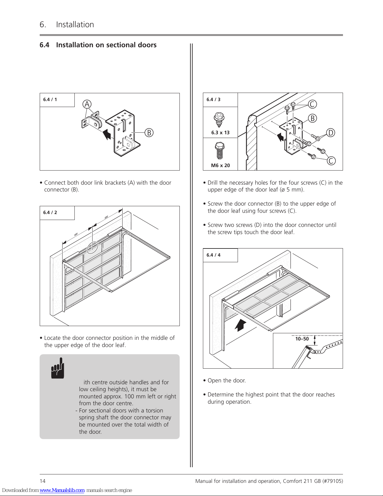
6.4 Installation on sectional doors
• Connect both door link brackets (A) with the door
connector (B).
6.4 / 2
6.4 / 1
B
B
C
D
C
• Drill the necessary holes for the four screws (C) in the
upper edge of the door leaf (ø 5 mm).
• Screw the door connector (B) to the upper edge of
the door leaf using four screws (C).
• Screw two screws (D) into the door connector until
the screw tips touch the door leaf.
A
• Locate the door connector position in the middle of
the upper edge of the door leaf.
a
a
a
a
a
a
a
a
a
a
a
a
aaa
a
a
a
a
a
a
a
a
a
a
a
aa
a
a
a
a
a
a
a
a
a
a
aa
a
a
a
a
a
a
a
a
a
a
aaa
a
a
a
a
a
a
aa
a
a
a
aa
a
a
a
a
a
a
a
aa
a
a
a
a
a
a
a
a
a
a
a
a
a
a
aa
a
a
a
a
a
a
a
a
a
a
a
a
a
a
a
a
aaa
a
a
a
a
a
a
a
a
a
a
a
aa
a
a
a
a
a
a
a
a
a
a
aa
a
a
a
a
a
a
a
a
a
a
aaa
a
a
a
a
a
a
aa
a
a
a
aaa
a
a
a
a
a
a
aa
a
aa
a
a
a
a
a
a
a
a
a
a
a
aa
a
a
a
a
a
a
a
a
a
a
a
a
aa
aa
a
a
a
a
a
a
a
a
aa
a
a
a
a
a
a
aa
aa
a
a
a
a
aa
a
a
a
a
a
a
a
a
a
aa
aa
aa
a
a
aa
a
a
a
a
a
a
a
a
a
a
a
aa
a
aa
a
a
aa
a
a
a
a
a
a
aa
a
a
a
a
a
a
a
a
a
a
a
a
aa
aaa
a
a
a
a
a
a
a
a
a
a
a
a
a
a
a
a
a
a
a
a
aaa
a
a
aa
a
a
a
a
a
a
a
a
a
a
aa
aa
a
a
aa
a
aa
a
a
aa
a
a
a
a
a
a
a
a
a
a
a
a
a
a
a
aa
a
a
a
a
aa
a
aa
a
a
a
a
a
a
a
a
a
a
a
a
a
a
a
a
a
a
a
a
a
a
a
a
a
aa
a
a
a
a
a
a
a
a
a
a
a
aa
a
a
a
a
a
a
a
a
a
a
a
a
a
a
a
a
a
a
a
aa
6.4 / 4
• Open the door.
• Determine the highest point that the door reaches
during operation.
10–50
Advice:
- If the door connector cannot be
positioned in the centre (for doors
with centre outside handles and for
low ceiling heights), it must be
mounted approx. 100 mm left or right
from the door centre.
- For sectional doors with a torsion
spring shaft the door connector may
be mounted over the total width of
the door.
M6 x 20
6.3 x 13
6.4 / 3
 Loading...