

Page 1
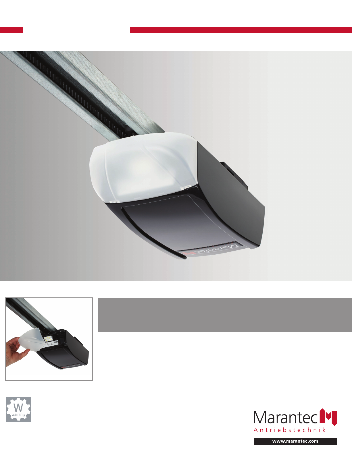
Synergy 260
The new Synergy Collection of garage door openers.
Faster, Brighter, Smarter, Stronger, Ultra Quiet.
The Synergy 260 is a feature-rich garage door operator system, built to last and
guaranteed to provide years of smooth, trouble-free performance. Innovative LED
lighting and reduced stand-by consumption make the Synergy 260 the most
efficient residential garage door opener available, while the direct current (DC)
Smart Motor , coupled with a chain or belt drive system, ensures an amazingly
quiet operation.
Limited Lifetime Warranty
on Motor, Gear Assembly
and Rail System. 2-year
Limited Parts Warranty
Part #120124 Version: 11/16
®
Page 2
Synergy 260 Specifications
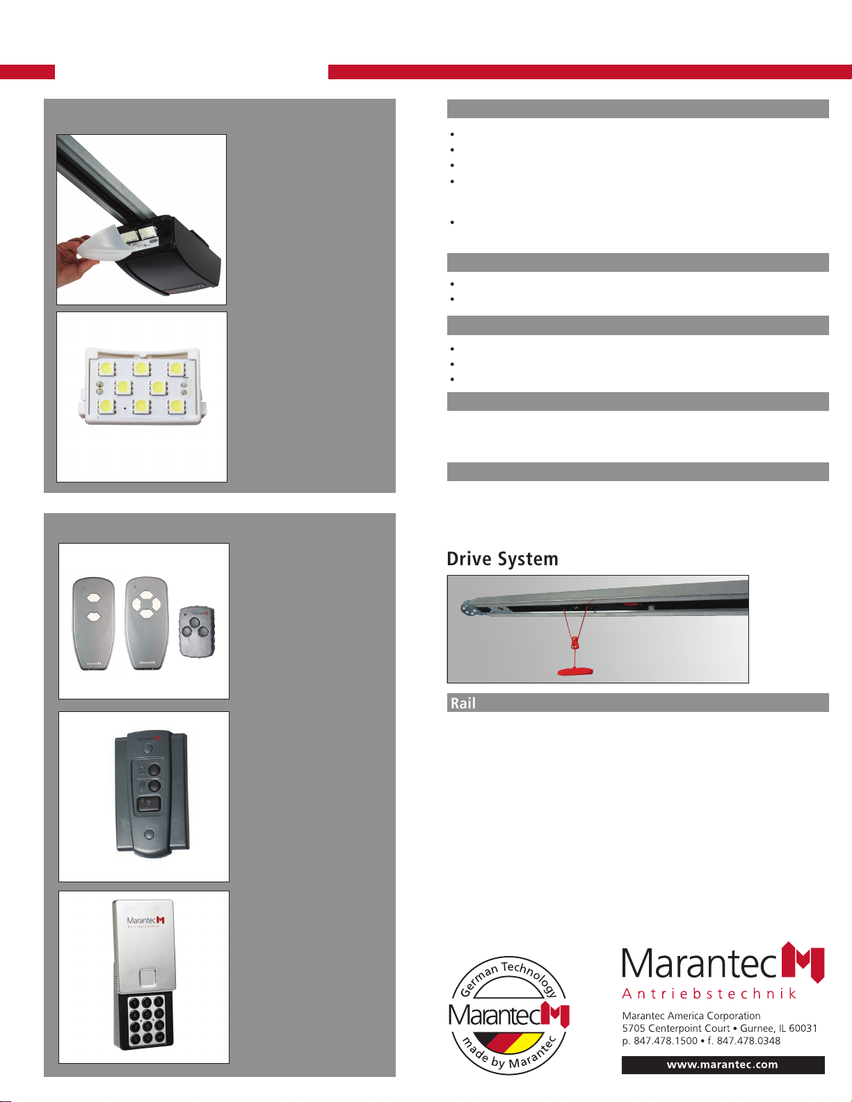
LED Lighting System
Accessories
Integrated seamlessly into
the motor housing, LED
lighting comes standard with
every Synergy operator. The
lens covers are completely
enclosed, meaning no
unsightly dirt and bugs under
the light covers
• LED lighting 80% – more
efficient than incandescent
light bulbs
• Longevity – LEDs have a
lifespan of over 30,000
hours.
• Cool Operation – LED
modules create more light,
while emitting less heat.
Transmitters
Two styles of digital remote
control transmitters in three
different configurations:
2-channel MINI, 4-channel
MINI (optional), and
3-channel MICRO (optional)
remotes for controlling other
devices. Unique and
extremely secure multi-bit
code technology.
Modular Multi-Function
Wall Station
Provides door operation and
convenience from inside the
garage. Compact, stylishly
designed to fit in a standard
single gang electrical box.
Illuminated push-button.
Security vacation/lock switch.
Light control. Individual
control stations can be
combined into one solid panel.
Wireless Keyless Entry
System (optional)
Convenient, 4-digit PIN.
Controls up to 4 different
garage doors. Code security.
Weather resistant.
Can be programmed to
provide temporary access
to authorized visitors or
service personnel.
Operator Features
DC motor provides for amazingly quiet operation
Opening and Closing Speed: 6.3 in/sec max
Push & Pull Force: 550 Newton (1/2 HPCS
Garage door opener is self-learning the operating force necessary to open and
close the garage door. Independently from the operating force, the opener
system monitors for obstructions during door travel.
Sealed motor gear case provides continuous lubrication to ensure a long service
life and and smooth, trouble-free operation.
™
)
Radio Controls
Frequency: 315MHz, Homelink® compatible
Technology: Multibit code
Lighting System
LED lighting system (included)
378 lumens expandable to approximately 756 lumens
Time controlled - lighting duration is programmable
Photo Eyes Safety System
State-of-the-art photo eye safety system detects obstructions in the path
of the door and automatically stops and reverses the downward door
travel. Safety when you need it most.
Warranty
Limited Lifetime Warranty on Motor, Gear Assembly and Rail System.
2 - year Limited Parts Warranty
5-year Limited Warranty on LED Lighting System
Drive System
Rail
The best in advanced engineering and materials. One piece
semi-closed fully assembled drive system with a high strength
galvanized steel finished C-rail, available with a steelreinforced belt or a full steel chain. A revolutionary trolley
release mechanism helps to prevent garage break ins.
Drive system’s overall length with attached operator 7ft. door: 10’- 6.25”
Door Heights Supported: 7ft, 8ft
Headroom Clearance Required: 1.25 inches
Trolley: Includes emergency release, easy reconnect, vault release compatibility
Page 3
Owner’s Manual contains:
Installation, operating,
maintenance & warranty
instructions.
Synergy 260, 270, 280
Marantec America Corporation
5705 Centerpoint Court, Gurnee, IL 60031 U.S.A.
Phone 1-888-622-2489
Fax 847-478-0348
Page 4

OWNER’S MANUAL CONTENTS
1. INTRODUCTION 3
2. ADVANCED FEATURES 3
3. IMPORTANT SAFETY INFORMATION 3
4. TOOLS 4
5. GARAGE 4
6. OPERATOR PACKAGE CONTENTS 6
7. IMPORTANT INSTALLATION INSTRUCTIONS 7
8. INSTALLATION STEPS 8
8-1. MEASURE AND MARK DOOR AREA 8
8-2. INSTALL HEADER BRACKET 8
8-3. INSTALL DOOR BRACKET TO DOOR 9
8-4. RAIL ASSEMBLY 10
8-5. ATTACH RAIL TO OPERATOR HEAD 11
8-6. ATTACH RAIL TO HEADER BRACKET 11
8-7. POSITION OPERATOR FOR MOUNTING 12
8-8. MOUNT OPERATOR TO CEILING 13
8-9. CONNECT ARM TO DOOR AND TROLLEY 13
8-10. RAIL BUMPER INSTALLATION 14
8-11. CHECK EMERGENCY RELEASE 14
8-12. INSTALL PHOTO EYE SAFETY SYSTEM 15
8-13. INSTALL WALL CONTROL PANEL 16
8-14. CONNECTING WIRES TO OPERATOR 16
9. CONTROL UNIT CONNECTIONS 17
10. CONNECT TO POWER 18
11. SYSTEM SET UP 19
12. ADVANCED SETTINGS 21
13. REMOTE CONTROLS 25
13-1. TRANSMITTER 25
13-2. WIRELESS KEYLESS ENTRY SYSTEM (OPTIONAL ACCESSORY) 26
14. OPERATION OF YOUR OPERATOR 27
15. HOMELINK® TRANSCEIVER 28
16. TEST SAFETY REVERSAL 29
17. ALIGN AND TEST PHOTO EYE SENSORS 29
18. APPLY LABELS TO INSIDE OF GARAGE 30
19. ATTACH OWNER’S MANUAL TO WALL 30
20. IMPORTANT SAFETY INSTRUCTIONS 30
21. TENSION ADJUSTMENT 31
22. RAIL LENGTH ADJUSTMENT - FOR PROFESSIONAL INSTALLERS ONLY 31
23. RAIL ASSEMBLY PARTS 32
24. ACCESSORIES 33
24-1. LED EL 200 33
24-2. EXTENSION BRACKET KIT 34
24-3. PERMANENT WIRING 35
25. TROUBLESHOOTING - FOR PROFESSIONAL INSTALLERS ONLY 36
26. MAINTENANCE AND ADJUSTMENTS 38
27. LIMITED PARTS WARRANTY 38
28. WARRANTY LIMITATIONS, CLAIMS AND SERVICE 40
29. REGISTRATION 40
30. WARRANTY SERVICE 40
C
Copyright 2015 All Rights Reserved.
Page 5
1. INTRODUCTION
Congratulations on purchasing your Marantec® Synergy Garage Door Operator System, the most innovative operator available today.
This stylishly designed digital operator with a wide range of accessories is engineered to provide the smoothest, quietest and safest operation to
compliment any application. Advanced technology results in the operator being capable of easily moving almost any properly balanced sectional
door, and at the same time providing state-of-the-art safety features to detect obstructions and to stop and reverse the door, thus helping to
protect persons and property near the door.
2. ADVANCED FEATURES
This operator includes numerous state-of-the-art features to provide you, the user, with years of trouble-free, convenient, and safe use of
your automatic garage door operator.
Advanced Digital Operating System EOS (Easy Operating System): The EOS digital system provides an user friendly
system set up. The EOS system requires only the initial set up parameters. All other operating parameters are learned and set
automatically by the system. In addition, the system optimizes all parameters with every cycle for a more efficient operation by
the GDO. This shorter parameter set up provides a quicker and more efficient installation.
New LED Lighting System: Provides a green energy efficient lighting approach to conventional incandescent lighting.
Added convenience requires no light bulb replacement.
Precision Controlled DC Motor, Complete with Automatic Soft Start and Soft Stop Feature: The operator
automatically detects when your door is almost fully closed or fully opened, and gradually slows the door down before it
reaches its fully closed or opened position. During start-up, the door starts moving slowly and gradually ramps up to full
speed for the full travel of your door. This reduces the possible damaging effects of the sudden starts and stops associated
with some other operators, and results in the smooth operation and increased service life of your door and hardware.
Quiet, Smooth Operation: Precision engineering and carefully selected materials result in extremely smooth and quiet
operation, unmatched by conventional garage door operators.
Modular Antenna Concept (patented): Plug-in your choice of frequency module.
Built-In Safety Features: Including patented drive system that delivers only the optimum power needed to move your door
safely - Every time!
Photo Eye (Infrared) Safety System: State-of-the-art infrared beam system helps detect obstructions in the path of
your door and automatically reverses closing door travel, helping to protect persons and property near the door.
LCD Display System Control: Easy navigation through levels and menus.
Convenient Status Display: To indicate the status of your door operator at any time. Especially useful if troubleshooting is necessary.
Numeric Parameter Display Setting: Provides easier and quicker setup.
Numeric Error Code Display: Provides quicker troubleshooting.
Maintenance and Service Scheduling: Optimizes operator service life and trouble-free performance.
The EOS platform unifies all Marantec Products by design.
Meets all UL 325 requirements.
3. IMPORTANT SAFETY INFORMATION
This manual is essential to the safe and proper installation, operation, and maintenance of your operator. Read and follow all
guidelines and operating instructions before the first use of this product. Store the manual in a safe, easily accessible location.
Operate the garage door operator at 120V, 60Hz to avoid operator damage.
Garage doors are heavy, moving objects. When coupled with an automatic operator, electrical power is also
present. If not properly installed, balanced, operated, and maintained, an automatic door can become
dangerous and cause serious injury or death. Please pay close attention to the WARNING and CAUTION notices
that appear throughout this manual. Failure to follow certain instructions may result in damage to the door or
door opener, or may result in severe injury or death to yourself or others.
WARNING means that severe injury
or death could result from failure
to follow instructions.
Mechanical
WARNING means that severe injury
or death could result from failure
to follow instructions.
Electrical
CAUTION means that property damage
or injury could result from failure
to follow instructions.
3
Page 6
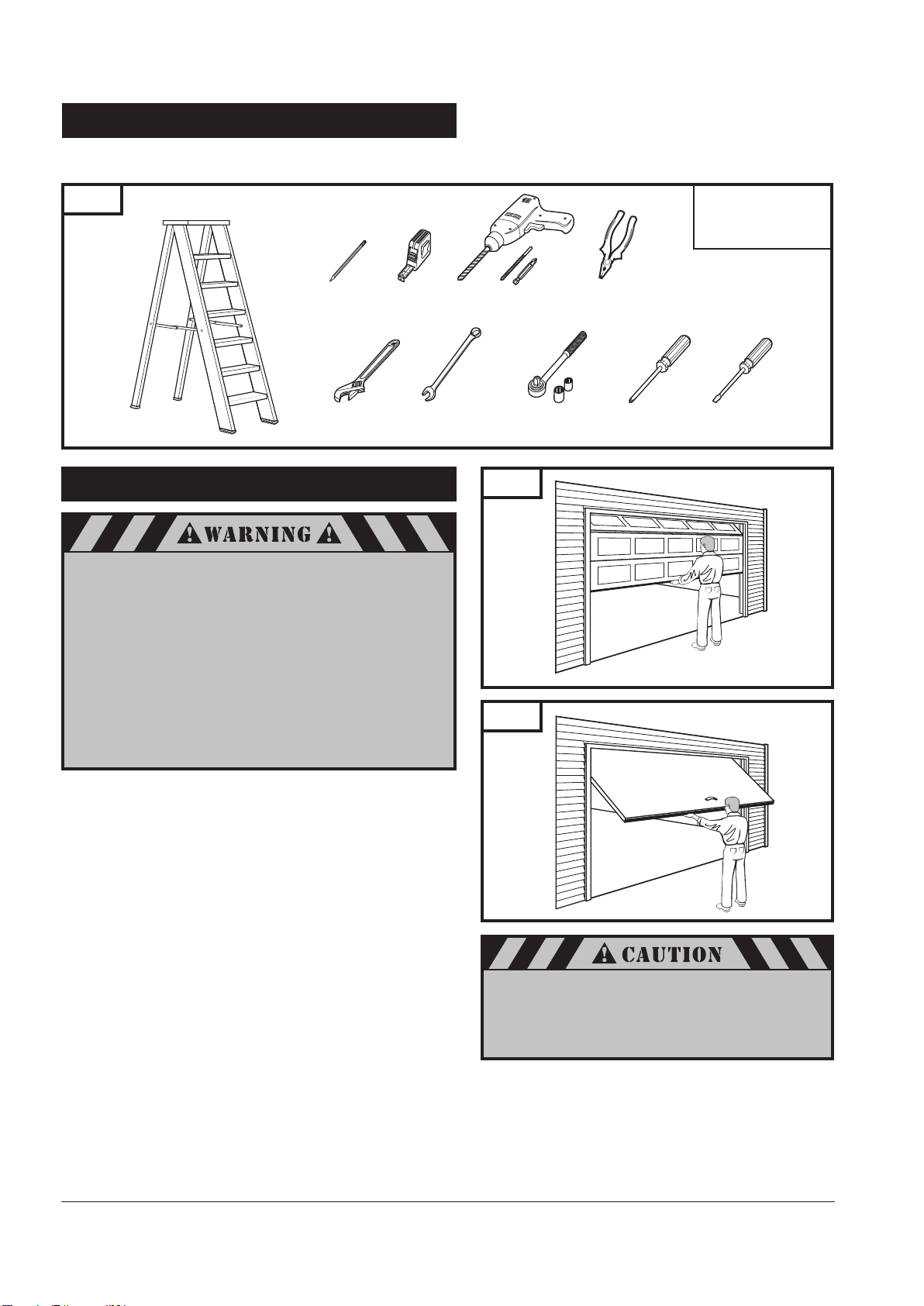
4. TOOLS
The instructions will refer to the tools shown below for proper installation, adjustment, and maintenance of the garage door
operator. Additional tools may be required depending on your particular installation.
Fig. 1
Stepladder
Pencil
Adjustable
Wrench
Tape Measure
7/16" Wrench
5. GARAGE
A garage door is a heavy moving object and can cause
serious injury or death. An unbalanced door might not
reverse when required, and can increase the risk of
injury. If your garage door is out of
balance, or if it binds or sticks, call for professional
garage door service. Garage doors, springs,
pulleys, cables, and hardware are under extreme tension
and can cause serious injury or death.
Do not try to adjust them yourself. Ropes left
on a garage door could cause someone to become
entangled and could kill them. Remove all ropes
connected to the door before installing your operator.
Drill,Drill Bits,
Phillips Power Bit
Ratchet and Sockets
(1/2", 7/16")
Fig. 2
Fig. 3
Pliers
Phillips
Screwdriver
Conversion:
1 foot = 305mm
1 inch = 25.4mm
Flat-Tip
Screwdriver
Sectional Door
One-Piece Door
Take a moment to survey your garage and garage door.
Is there an access door besides the garage door? If not, you
should install an emergency key release kit.
With the garage door closed, check alignment of door and
garage floor. The gap, if any, should be no more than
1/4" (6mm). If the gap is larger than this, repair floor or door
before installing operator.
The operator is intended for installation on a properly balanced
and adjusted garage door. DO NOT INSTALL IF DOOR IS
UNBALANCED OR BROKEN.
Check balance of door in mid travel and during full range of
opening and closing. Lift the door about half way, as shown in
Fig. 2 & 3. Release the door. It should remain in place,
supported by its springs. Raise and lower the door fully to
check for binding or sticking.
If door is out of balance or needs repair, DO NOT ADJUST IT
YOURSELF. CALL A QUALIFIED GARAGE DOOR SERVICE
PROFESSIONAL to adjust your door.
If your door is over 7 ft. (2.1m) high, you will need a longer
rail. See section 6 “Rail Assembly” on p. 6 of this manual for
availability of longer rails.
4
To prevent damage to steel, aluminum, fiberglass
or glass panel doors, always reinforce the inside of
the door both vertically and horizontally with steel
or angle iron bracing.
The best solution is to follow the instructions for your
particular garage door or contact the garage door
manufacturer for proper reinforcement instructions.
Page 7
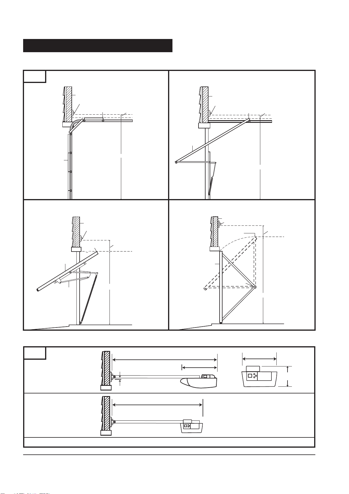
5. GARAGE (cont’d)
Header Wall
Check the type of door construction you have. The information contained in the figures below will be referred to later in the
Check the type of door construction you have. The information contained in the figures below will be referred to later in the
manual for proper installation on the different door types.
manual for proper installation on the different door types.
Fig. 4
Door
Header Wall
Header Bracket
Highest Point of
Header Wall
Header Bracket
Highest Point of
Door Travel
Sectional Door
with Curved Track
Door Travel
1-1/4” (30mm) Clearance
Distance
One-Piece Door
with Jamb Hardware without Track
3-3/4” (95mm) Clearance
Door
Header Wall
Header Bracket
Header Bracket
Highest Point of
Door Travel
Highest Point of
Door Travel
One-Piece Door
with Horizontal Track
1-1/4” (30mm) Clearance
Distance
One-Piece Door
with Pivot Hardware without
Track
3-3/4” (95mm) Clearance
Door
Jamb
Hardware
Distance
Door
GARAGE DOOR OPERATOR SYSTEM OVERALL DIMENSIONS 7' DOOR (2.1m)
Fig. 5
Standard Application
Space Saver Application
10' 6-1/4" (3.21m)
14-1/4" (360mm)
1/2" (13mm)
10' 3/4" (3.07m)
Pivot
Distance
7-1/2" (190mm )
5" (125mm )
Headroom Clearance - 1-1/4” (32mm)
5
Page 8
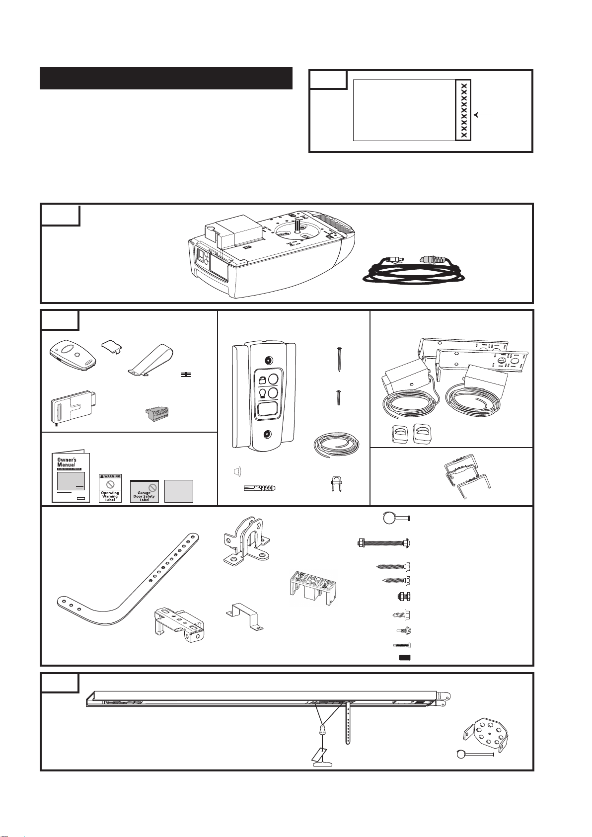
6. OPERATOR PACKAGE CONTENTS
Fig. 6
Remove one of the serial number labels located on both sides
of operator carton and apply to the front page of owner’s
manual. See Fig. 6.
Removable
serial number
Remove second serial number label and apply to the warranty card.
Operator’s manufacturing date is located under operator lens cover.
The following items are included with your Garage Door Operator (GDO). All hardware components are located in the GDO
carton. The accessories are packaged with their respective hardware in separate packs for ease of identification and use.
Items shown not actual size.
Fig. 7
Fig. 7A
Transmitter
OPERATOR
ACCESSORIES
Cover
Visor Clip
Modular
Receiver
Programming
Connector
Terminal
Block
Garage Door Operator Manual and Safety Labels
Warranty
Card
Wall Control Panel
(with Hardware Kit)
Screw Caps (2)
Drywall Anchors (2)
Tapered-Head Screws
(2)
Machine screws
(2)
30 Ft. (9.2m)
2-Conductor Wire
Staples (10)
6 Ft. (1.8m) Detachable Power Cord
Photo Eye Sensor Safety System
(with accessories)
Sensor (TX)
Sensor (RX)
Sensor Lens Cap Protectors (2)
Wire Holder Kit
Bracket (2)
5“
6“
5.5”
5“
6“
5.5”
5“
6“
Hardware Kit
Curved Door Arm
#8009466
Support Bracket (2)
#71865
Fig. 8
RAIL ASSEMBLY
(packaged in separate carton)
Models (per application)
Belt Chain
7’ (2.1m) Door M13-807B M13-807C
8’ (2.4m) Door M13-808B M13-808C
10’ (3m) Door M13-810B M13-810C
6
Door Bracket
#8030743
Rail Bracket (2)
#99082
Bumper
#102723
Clevis Pin (1): 5/16” x 7/8”
Cotter Ring (1)
Carriage Bolt (2): 1/4” - 20 x 2”
Lock Washer (2): 1/4”
Hex Nut (2): 1/4” - 20
Lag Screw (2): 5/16” x 1-3/4”
Lag Screw (4): 1/4” x 1-1/2”
Hex Bolt (2): 5/16” - 18 x 3/4”
Lock Nut (2): 5/16” - 18
Hex Head Tek Screw (2): 1/4” x 3/4”
Screw (4): M5x8.5mm
Screw (2): 3.9x32mm
Cap (2) #104740
Header Bracket Kit
#103238
(Clevis Pin 1/4” x 3 1/14”)
Page 9
7. IMPORTANT INSTALLATION INSTRUCTIONS
IMPORTANT INSTALLATION INSTRUCTIONS
TO REDUCE THE RISK OF SEVERE INJURY OR DEATH:
1. READ AND FOLLOW ALL WARNINGS AND INSTALLATION INSTRUCTIONS.
2. Check with the door manufacturer to determine if additional reinforcement is required to support the door prior to
installation of the door operator.
3. Install operator only on a properly balanced garage door. An improperly balanced door could cause serious injury.
Have a qualified service person make repairs to garage door cables, spring assemblies, and other hardware before
installing the operator.
4. Remove all ropes and disable all locks connected to the garage door before installing operator.
5. If possible, install the door operator 7 feet (2.1m) or more above the floor. For products having an emergency
release, adjust the emergency release cord for the handle to be within reach, but at least 6 feet (1.8m) above the
floor and avoiding contact with vehicles to avoid accidental release.
6. Do not connect the operator to source of power until this manual instructs you to do so.
7. Locate the wall control station: (a) within sight of door, (b) at a minimum height of 5 feet (1.5m) above the ground
so small children cannot reach it, and (c) away from all moving parts of the door.
8. Place the Operating Warning Label next to the wall control panel in a prominent location. Affix Safety Label on
inside of garage door. The Emergency Release markings molded on handle.
9. After installing the operator, test Safety Reversal System. Door MUST reverse when it contacts a 1-1/2 inch (40mm)
high object (or a 2x4 laid flat) on the floor.
10.
SAVE THESE INSTRUCTIONS
For Important Safety Instructions see page 30.
for future safety, adjustment, and maintenance purposes.
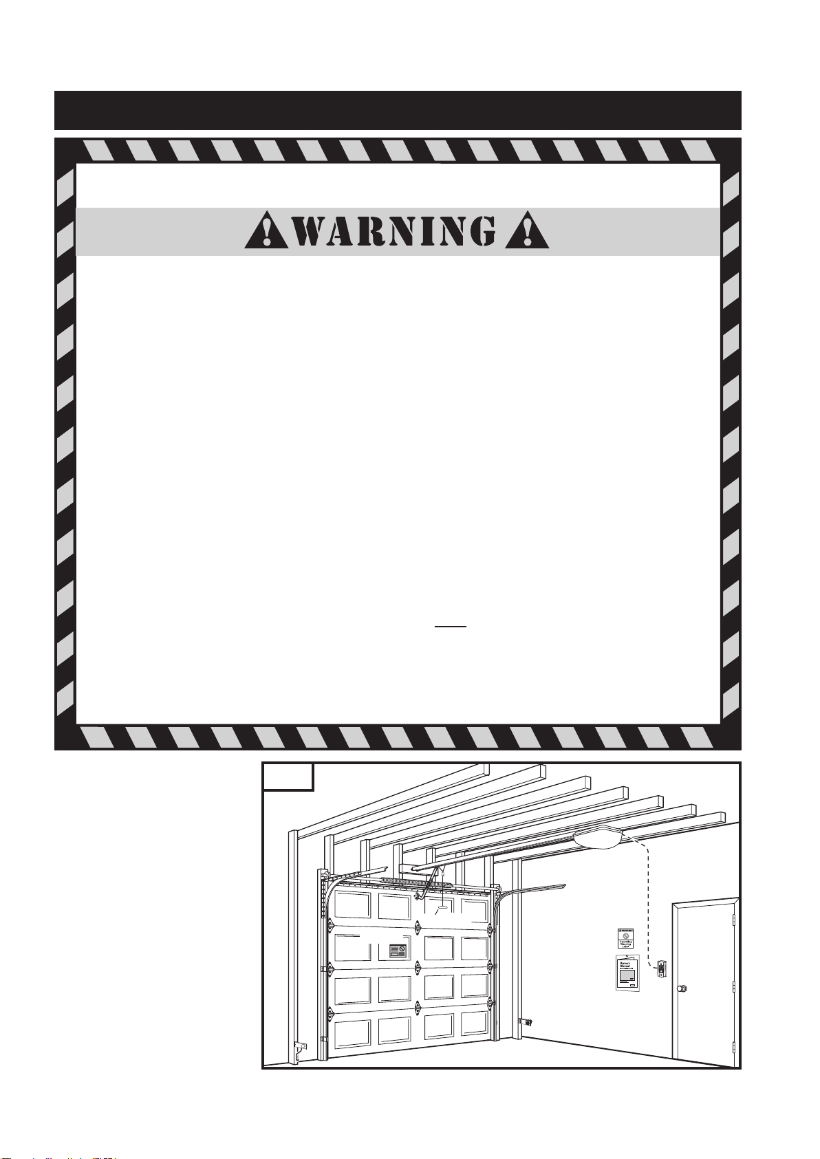
Fig. 9
Shown on the right is an
overall view of a completed
garage door operator system
installed on a sectional door.
The arrangement is similar for
a one-piece door (except for
differences described later in
this manual).
Garage Door
Safety Label
Emergency
Release Handle
Operating
Warning
Label
Owner’s
Manual
7
Page 10
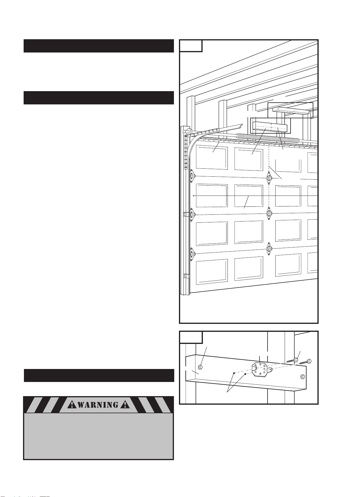
8. INSTALLATION STEPS
Identify a sound structural support on header wall above garage
door for header bracket mounting. See Fig. 11. If appropriate
header does not exist, replace or install a new support using a 2x4
(50mm x 100mm) or 2x6 (50mm x 150mm) board. Fasten it securely
using lag screws (not provided) to structural supports of garage.
Fig. 10
8-1. MEASURE AND MARK DOOR AREA
Before starting your installation, the door and the header above
the door must be measured and marked. This way, the appropriate brackets can be mounted at the correct locations avoiding
installation and operating difficulties later.
MARK VERTICAL CENTER LINE:
Measure door width, then locate the center point (Fig. 10).
Mark a vertical line on the upper half of your door, on the top
edge of your door, and on the header, through the center
point.
MEASURE DOOR’S HIGHEST TRAVEL POINT:
(Review Figs. on p. 5 for details)
Open door to its highest travel point and measure from the
garage floor to the top of door.
Write down this distance.
FOR SECTIONAL DOORS AND ONE-PIECE DOORS WITH
HORIZONTAL TRACK:
Add 1-1/4" (30mm) to the door travel height (measured above).
FOR ONE-PIECE DOORS WITHOUT TRACK:
Add 3-3/4" (95mm) to the door travel height (measured above).
Horizontal
Reinforcement
Bracket
See Fig. 11
Door Width
Header
See Fig. 12
Horizontal Line for
Header Bracket
Height
Vertical
Center Line
MARK HORIZONTAL LINE FOR HEADER BRACKET
LOCATION:
Close door and measure the required distance (determined
above) from the garage floor to the header.
Mark a horizontal line, intersecting the vertical center line, on
header. This is the position at which the bottom of the header
bracket should be installed.
In case of minimal clearance above the door, the header
bracket may be mounted to the ceiling. In this case, extend
the vertical center line onto the ceiling, and mark a horizontal
line on the ceiling no further than 4" (100mm) from the
header wall. The header bracket should be mounted no
farther than this distance from the header wall.
8-2. INSTALL HEADER BRACKET
Header bracket kit located in rail carton.
If the header bracket is not rigidly fastened to a sound
structural support on the header wall or ceiling, the
safety reverse system may not work and could cause
serious injury or death. DO NOT move or adjust springs
or garage door hardware, as these parts are under
extreme tension and could cause injury or death.
Fig. 11
Header
Lag Screw for Header installation
if necessary (not provided)
Header Bracket
Pilot Holes
5/16” x 1-3/4"
Lag Screw
8
Page 11
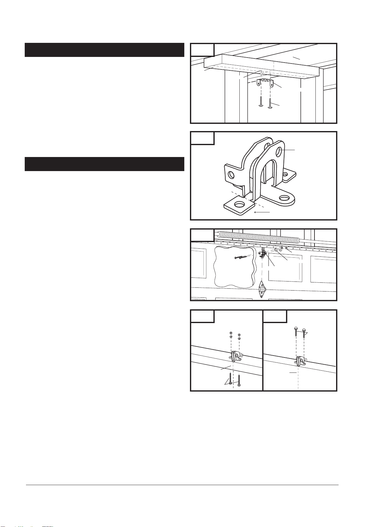
8-2. INSTALL HEADER BRACKET (cont’d)
Mark pilot holes location on header through header bracket
holes where lag screws will be inserted.
IMPORTANT: See Fig. 11 for which header bracket holes to
use.
Drill 3/16" pilot holes into header, and install bracket with lag
screws (5/16” x 1-3/4”) provided.
Tighten lag screws firmly.
NOTE: Follow the same procedure if header runs vertically
instead of horizontally and is the only option for mounting
header bracket to header wall. In case of minimal clearance
above the garage door, the header bracket may be
mounted to the ceiling (Fig. 12). Follow the same steps
above to ensure a sound surface for mounting.
8-3. INSTALL DOOR BRACKET TO DOOR
A. FOR SECTIONAL DOORS:
Wood Sectional Doors (Fig. 14)
Position door bracket (Fig. 13) along vertical center line of
door with pin hole facing top of the door and top edge of
the bracket 4” to 5” (100mm - 125mm) below top edge of
the door, or roughly at the same height as top rollers on the door.
Mark locations of securement holes through door bracket.
Drill two 1/4" holes through door for securement of door
bracket.
Insert carriage bolts (1/4” x 2”) from the outside through
door and bracket, then secure with lock washers and nuts
from the inside.
Tighten nuts firmly.
Metal Sectional Doors
Attach door bracket with two teck screws (provided) per Door
manufacturer recommendations.
B. FOR ONE-PIECE DOORS:
Before starting the installation of the door bracket, cut off
mounting leg from opposite side of pin hole (Fig. 13).
One-Piece Doors with Exposed Frames (Fig. 15)
Position center of door bracket on the center line on the top
edge of door.
Mark the position where carriage bolts will go through
bracket, and drill two 1/4" holes through top frame of door.
Install carriage bolts from the bottom, through door frame
and bracket, and secure with lock washer and nut from top.
Tighten nuts firmly.
One-Piece Doors without Exposed Frames (Fig. 16)
For doors without exposed frames, use alternate method of
mounting door bracket.
Mark and drill two 3/16" pilot holes into top of frame, then
secure bracket with 5/16" x 1-5/8" lag screws (not provided).
Fig. 12
Header
Pilot Hole
Fig. 13
Cut off for one-piece
door only
Fig. 14
Insert 1/4”-20 x 2”
Carriage Bolts
from outside of door
Door Bracket
Fig. 15 Fig. 16
Garage Door
Center Line
Carriage Bolts
One-Piece Door
with Exposed Frame:
Install with Carriage Bolts
Garage Door
Center Line
without Exposed Frame:
Install with Lag Screws(not provided)
Ceiling
Header Bracket
Lag Screw
Pin Hole
1/4”-20 Nut
Lock Washer
Wood Sectional
Doors
Lag Screws
One-Piece Door
9
Page 12
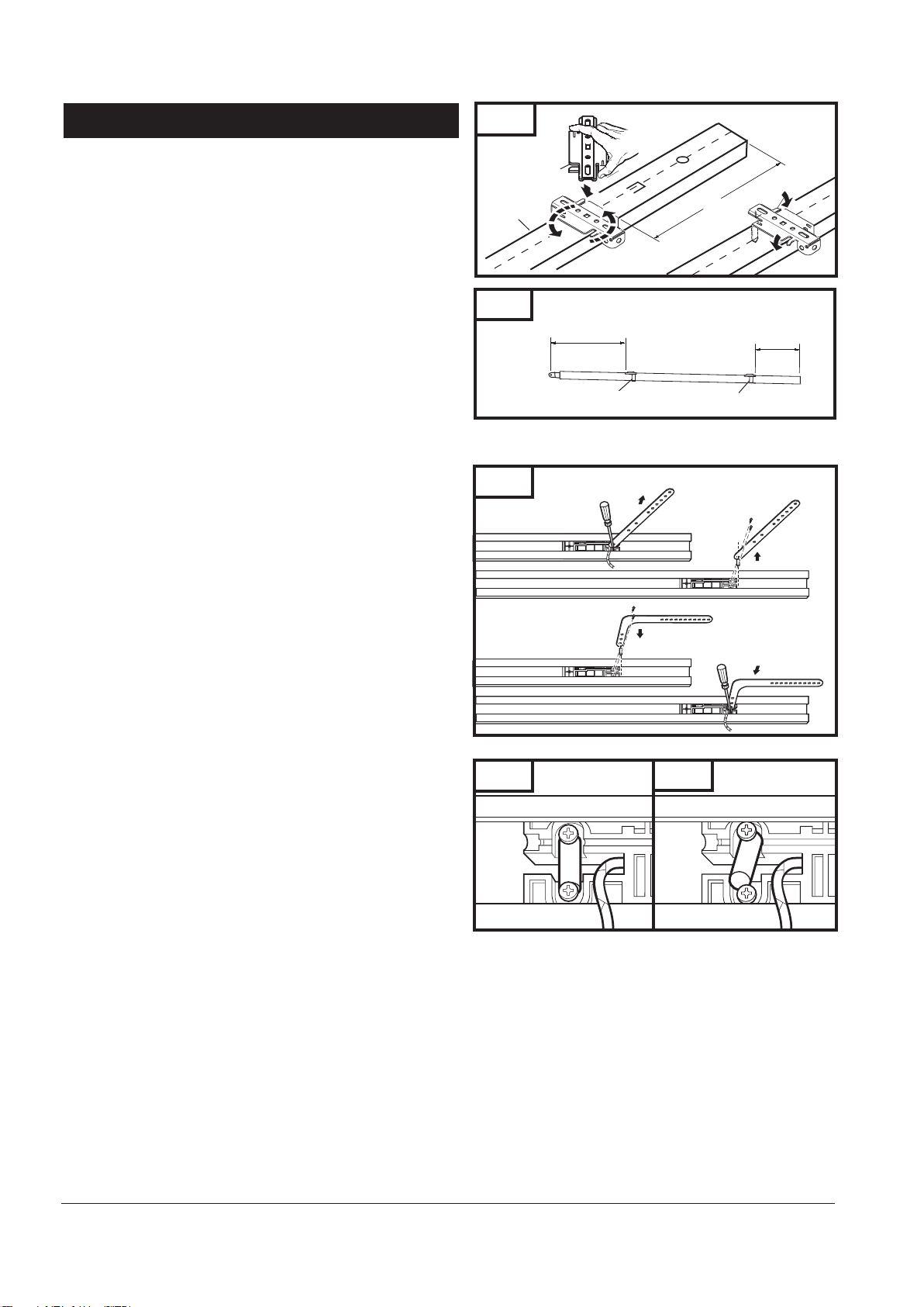
8-4. RAIL ASSEMBLY
NOTE: Rail comes fully preassembled with straight door arm
already attached.
Unpack one-piece preassembled rail.
Leave straight door arm taped inside rail for safe and convenient
installation—it will be untaped and used later.
Place mounting bracket over rail (close side) on a diagonal.
Make sure support securement clamps clear rail sides.
Twist mounting bracket and secure onto rail 12” (305mm)
from spracket end side of rail as shown in Fig. 17.
Place second mounting bracket over the backside of the rail 33”
(840mm) from pin hole. See Fig. 17A.
Secure second bracket as shown on Fig. 17.
Fig. 17
Mounting Bracket
Rail
Fig. 17A
33”
(840mm)
12”
(305mm)
12”
(305mm)
ADDITIONAL STEP FOR ONE-PIECE DOORS ONLY:
IMPORTANT NOTE: For installation on One-Piece Doors only,
the straight door arm that is factory installed onto the rail
must be replaced by the curved door arm supplied as part
of hardware in the operator box.
Recommended: Replace arm after attaching rail to operator.
Turn rail over so that open channel in rail faces up.
Untape straight door arm that is secured inside rail.
Remove and save the two phillips head screws that are securing
the door arm pin and straight door arm (Fig. 18).
Lift arm and pin straight out of slot in trolley, and remove pin
from straight door arm.
Insert pin into short side of curved door arm as shown.
Orient arm so that long side extends away from trolley.
Carefully insert pin and door arm into slot in trolley.
Push pin into slot with door arm so pin is fully seated into trolley
slot. IMPORTANT: Pin must be straight and seated properly
into recessed area in trolley. See Figs. 18A and 18B.
Secure pin and curved arm with the two phillips screws which
were removed from trolley—DO NOT use any other screws.
Tighten screws firmly.
Mounting Bracket
Fig. 18
C. Feed Pin though Curved
Door Arm Hole
Fig. 18A
Correctly seated pin.
Mounting Bracket
A. Loosen Screws
D. Reinsert Pin and Arm Firmly
and Squarely, Tighten Screws
Fig. 18B
Incorrectly seated pin.
B. Remove Pin
10
Page 13
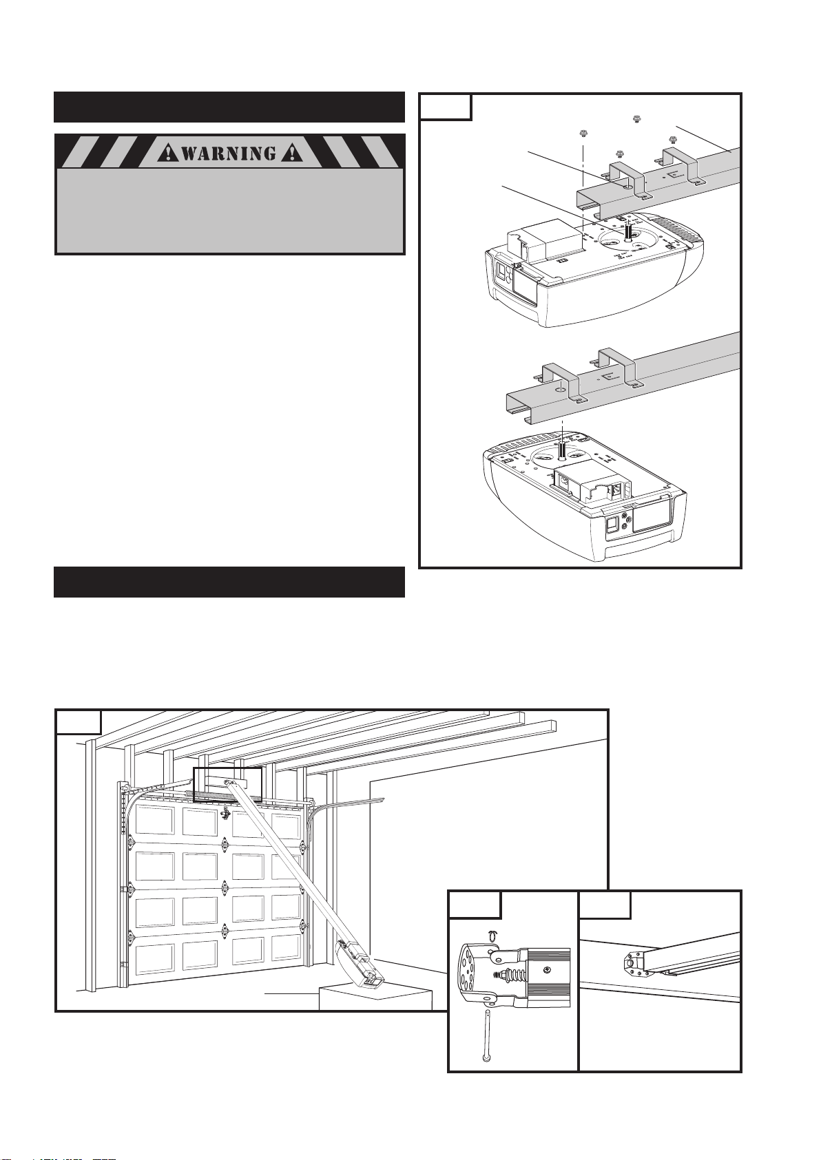
8-5. ATTACH RAIL TO OPERATOR HEAD
Fig. 19
Standard Application
Rail
Sprocket
Opening
When fastening the rail to the operator,
use only the screws provided. Use of any
other screws may result in operator falling
from ceiling and causing damage
to persons or property in the garage.
Position operator with control panel facing back of garage.
Rest operator head on cardboard or protective surface on floor
so opener does not get scratched.
Position rail onto operator chassis by lining up rail sprocket
opening with motor head shaft (Fig. 19). Make sure shaft
engages teeth inside rail sprocket. Press rail down firmly onto
shaft and opener chassis. DO NOT HAMMER.
Position the two rail brackets over rail as shown in Fig. 19.
Insert screws (M5 x 8.5) through bracket holes and into chassis
holes, and tighten screws firmly to hold rail to head.
Motor Head
Shaft
Alternate Rail Installation
(Space Saver Applications)
8-6. ATTACH RAIL TO HEADER BRACKET
Support operator head slightly off the floor.
Lift the opposite end of the rail up to the header bracket.
Position rail end-stop within the openings in the header
bracket. Insert header clevis pin (1/4” dia.) through header
bracket and rail end, then attach cotter ring to end
of pin. (See Fig. 20A)
Fig. 20
Fig. 20A Fig. 20B
Cotter Ring
Operator Box
1/4” x 3-1/4"
Clevis Pin
11
Page 14
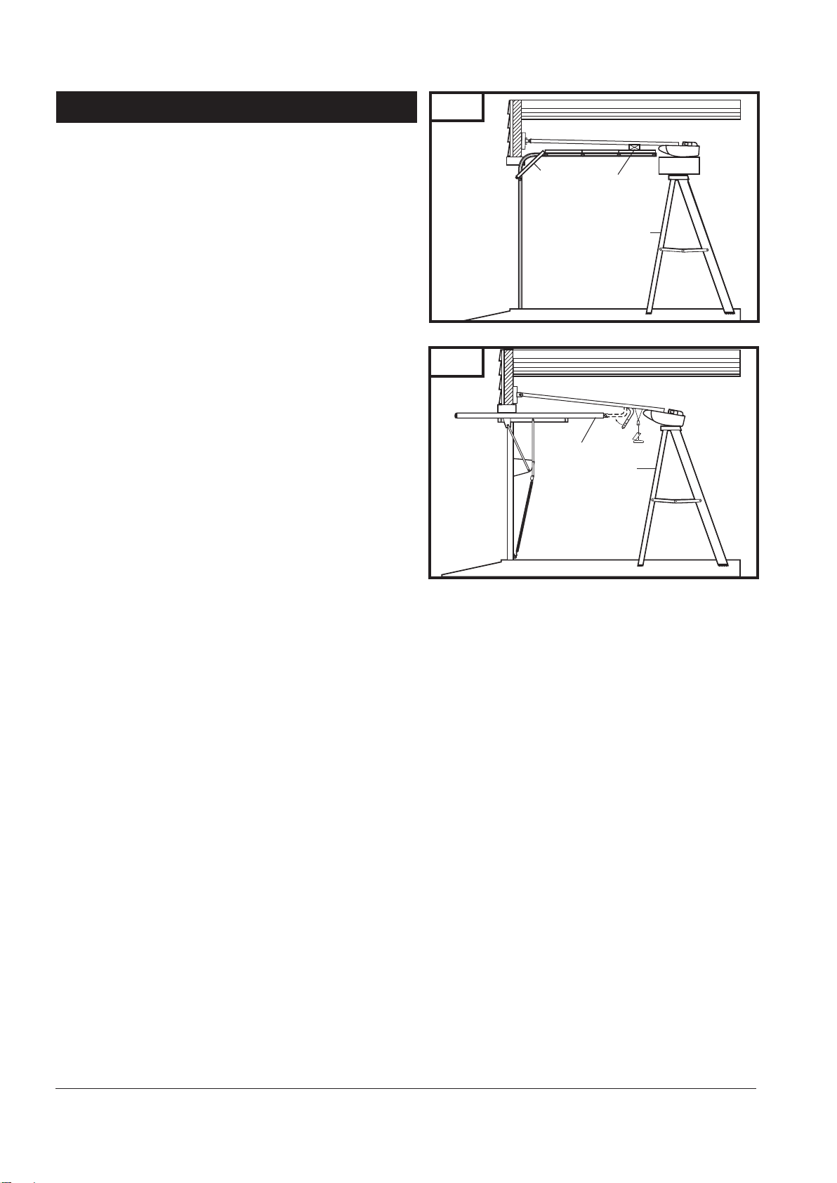
8-7. POSITION OPERATOR FOR MOUNTING
Once rail is attached to header bracket, support operator on ladder,
or use the assistance of another person to support operator high
enough so door can open without hitting the rail.
A. SECTIONAL DOORS AND ONE-PIECE DOORS WITH
TRACK:
Open garage door to fully opened position, and place a
2x4 (50mm x 100mm) laid flat between the door and the rail.
See Fig. 21. This provides an easy method of ensuring the
correct mounting height of the opener.
B. ONE-PIECE DOORS WITHOUT TRACK:
Move trolley toward opener head.
Open door all the way so that it is parallel to the floor, or
slightly tilted toward the front of the garage. DOOR SHOULD
NOT BE TILTED TOWARD THE BACK OF GARAGE.
Position operator so that top of operator head is level with top
of opened door.
To check for correct mounting height, temporarily position
curved door arm as if connecting to door bracket. See Fig. 22.
The long side of the arm should be parallel to the floor when
door is fully opened. Raise or lower powerhead so that arm
will be parallel to floor.
Temporarily support head at this height, and prepare to
mount the operator to ceiling.
Fig. 21
Fig. 22
Door
2x4 Laid Flat
(50mm x 100mm)
Stepladder
Door
Stepladder
12
Page 15
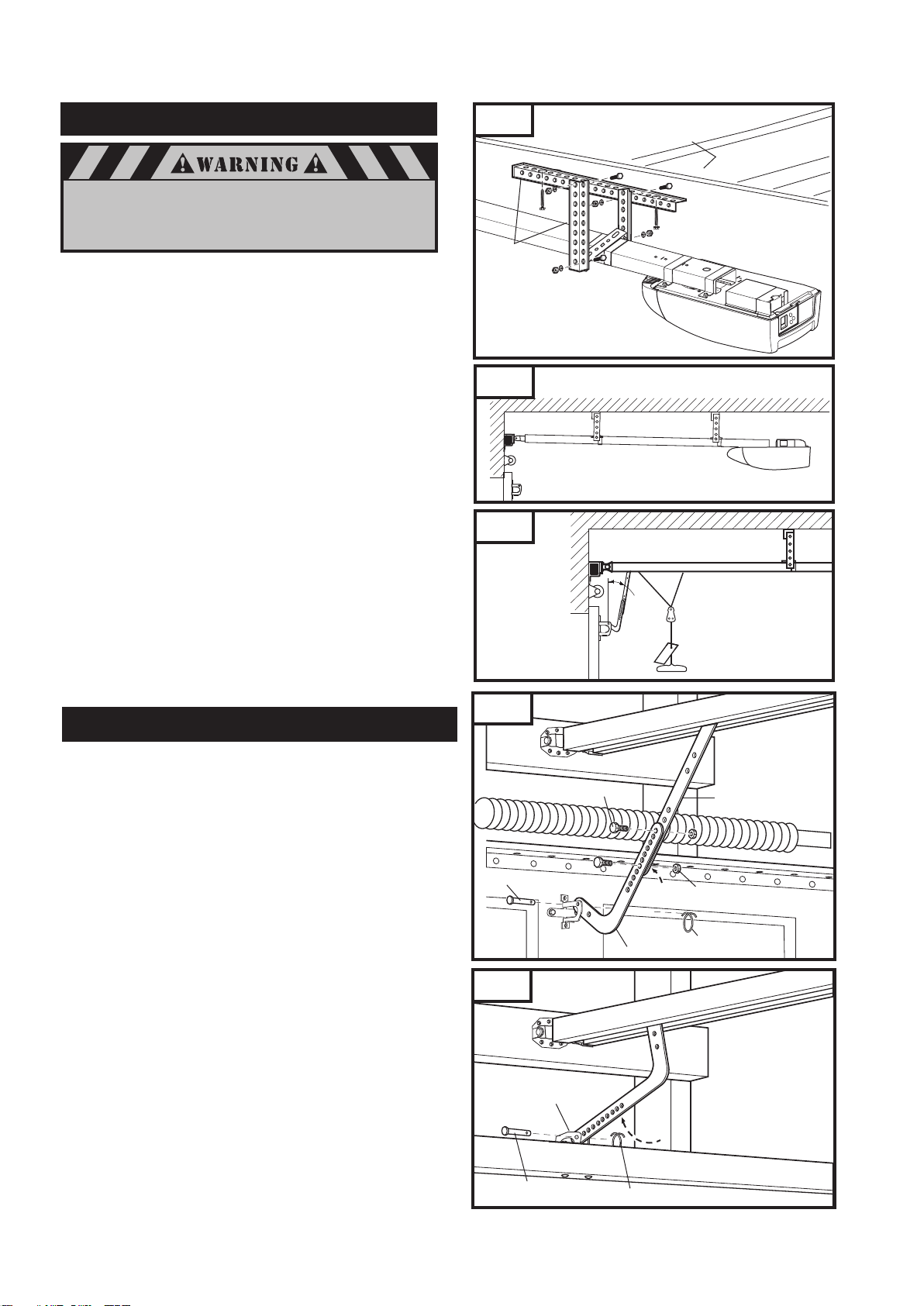
8-8. MOUNT OPERATOR TO CEILING
If not properly secured, the operator could fall and injure
someone. Secure opener to structural supports or
framing. Do not mount to drywall, plaster,
or other such material.
Position opener head so that rail is lined up with center line
of open door.
Line up sturdy perforated angle (not provided) with
ceiling joists above rail mounting bracket. In case of finished
ceiling use stud finder to locate joists.
Mark location for 5/16” x 2” lag screws (not provided), and
drill two 3/16” pilot holes.
Fasten sturdy perforated angle to joists using lag screws.
Measure distance from each side of mounting bracket to the
perforated angle.
Cut pieces of hanging brackets (perforated angles) to
required lengths.
Attach one end of each hanging brackets to rail mounting
brackets with 5/16”-18 x 7/8” hex bolts, 5/16”-18 nuts, and
5/16” lock washers (hardware not provided).
Fasten another end of hanging brackets to perforated angles
using the same hardware.
Once opener is securely fastened in position, remove wood
block and lower door. Check door for proper operation and
clearance by manually moving door to full open and closed
position. If door hits rail at any point, raise opener head slightly
higher and re-mount in position.
Mark location and drill pilot holes for second perforated angle
which will be located above second mounting bracket.
Follow the same steps above for second mounting bracket. See Fig. 24.
8-9. CONNECT ARM TO DOOR AND TROLLEY
Fig. 23
Joists (may be hidden
behind drywall)
Perforated angle
Fig. 24
Fig. 25
Angle
Fig. 26
Make sure door is fully closed.
Remove tape from rail holding straight door arm
(sectional door only) and allow door arm to hang freely.
A. SECTIONAL DOORS:
Position curved door arm into door bracket channel so that
short end of arm will be attached to door bracket.
See Fig. 26. Curved door arm should be attached roughly at
the same height as the top rollers of the door.
Align curved door arm and bracket holes, then insert clevis pin
through holes. Attach cotter ring to hold pin in place.
Position straight arm and curved arm to form an angle with
the door (Fig. 25) and at least two sets of holes line up.
Select two overlapping holes as far apart as possible and
secure arms together with hex bolts 5/16”-18 x 3/4“ and
5/16”-18 lock nuts
B. ALL ONE-PIECE DOORS:
Curved door arm should already be attached to trolley in place
of straight door arm. See Fig. 18, p. 10.
Position free end of curved arm into door bracket slot.
Align curved door arm and bracket holes, then insert clevis
pin (5/16” dia.) through holes. Attach cotter ring to pin to
hold in place. See Fig. 26A.
C. SECTIONAL AND ONE-PIECE DOORS:
After connecting appropriate door arm, ensure trolley is
disengaged. Check for proper door operation by manually
lifting then lowering to fully opened and closed positions.
Readjust door arm if needed.
5/16"-18x3/4" Hex Bolt
5/16"x7/8" Clevis Pin
Fig. 26A
Door Bracket
(for One-Piece Door)
Clevis Pin
Curved Door Arm
Cotter Ring
Straight Door Arm
5/16"-18
Lock Nut
Cotter Ring
13
Page 16
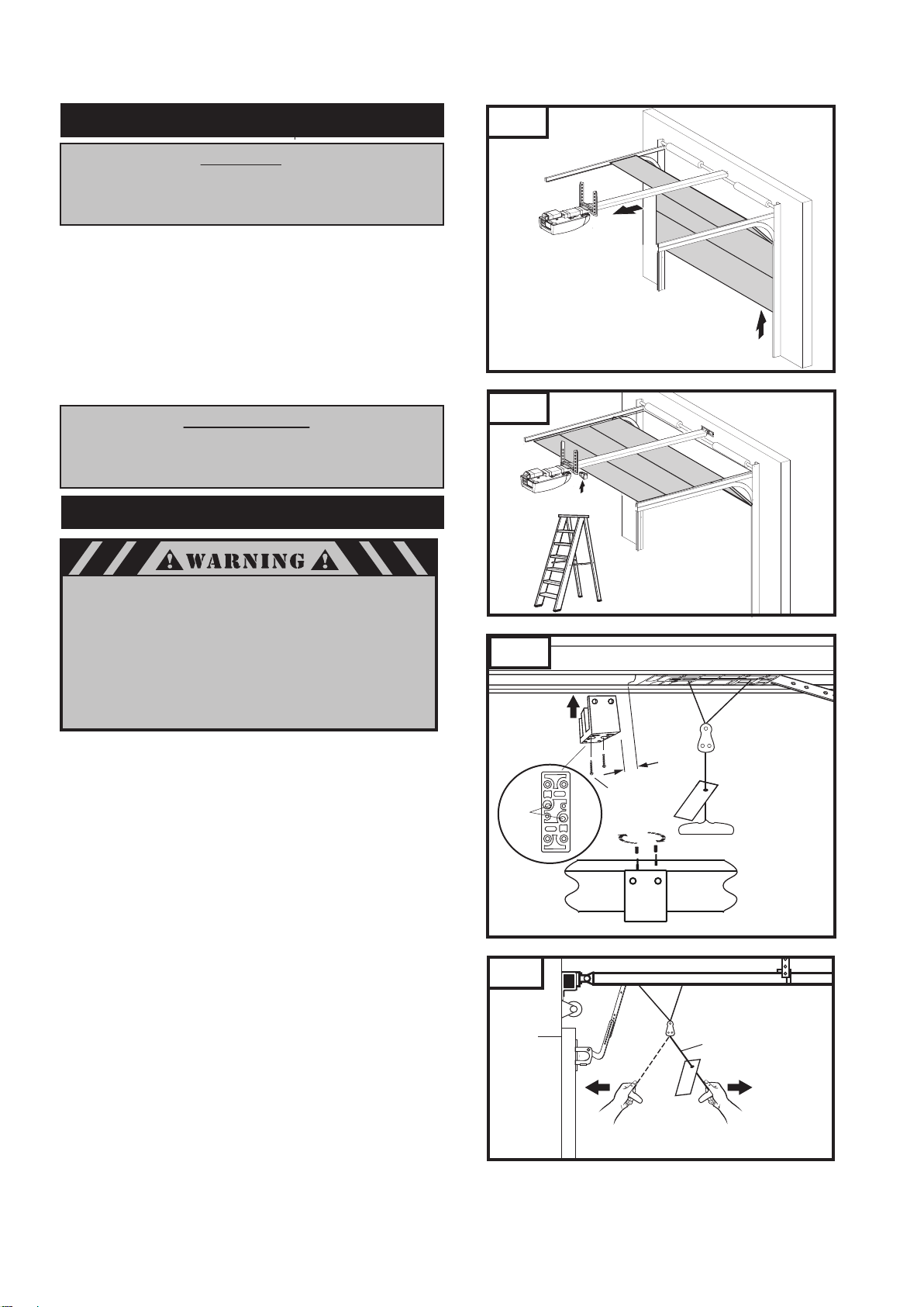
8-10. RAIL BUMPER INSTALLATION
ATTENTION
THE RAIL BUMPER IS AN IMPORTANT PART OF GARAGE
DOOR OPERATOR SYSTEM. THE BUMPER IS DESIGNED FOR
SETTING UP AND MONITORING THE OPERATOR’S TRAVEL LIMITS.
With the trolley still in the unlocked position, manually move door
up to the desired location. See Fig 27.
Snap rail bumper into place as shown in Fig. 28.
Hold door and measure 1/2” (13mm) between trolley
end and the bumper as shown in Fig 29. This is the installation
location for the rail bumper.
Important: The distance between the trolley and the
bumper should not be greater than 1/2”.
Secure bumper with self-tapped 3.9 x 32mm screws provided.
Cover screws with plastic caps provided as shown on Fig. 29.
IMPORTANT NOTE
PULL RELEASE HANDLE TOWARDS DOOR FRAME TO LOCK
TROLLEY, THEN MOVE DOOR MANUALLY UNTIL TROLLEY
LOCKS WITH CHAIN OR BELT CONNECTOR.
8-11. CHECK EMERGENCY RELEASE
Fig. 27
Fig. 28
To prevent possible SERIOUS INJURY or DEATH from a
falling garage door:
• If possible, use emergency release handle to disengage
trolley ONLY when garage door is CLOSED. Weak or
broken springs or unbalanced door could result in an
open door falling rapidly and/or unexpectedly.
• NEVER use emergency release handle unless garage
doorway is clear of persons and obstructions.
• NEVER use handle to pull door open or closed.
The release cord with handle should be adjusted to hang
6 ft. (1.8m) above garage floor.
To adjust:
Slide handle up on cord.
Tie new knot at correct height.
Cut excess cord, leaving approximately 1” (25mm) after knot.
Heatseal end of cord with match or lighter to prevent fraying.
Slide handle back into place.
The emergency release cord with red handle which is already
attached to the trolley, are extremely important parts of the
operator system. Pulling the release cord see Fig. 30 disengages
the door from the opener. This allows the door to be moved
manually up and down independent of the opener motor.
If the door is in the open position, use extreme care when
using the release.
Use emergency release to disconnect the door if the power is out. This
allows the door to be moved manually up and down independent of
the operator motor. It should also be used if for some unforeseen
reason the door strikes a person or object during its travel and does
not automatically reverse off the obstruction.
To release door—pull emergency release handle toward the
operator at approximately 45 degrees. (Fig. 30)
Prior to re-engaging door, ensure that all obstructions are removed and
door is operating properly manually. Before re-engaging trolley with a
belt connector, pull handle toward the door at approximately a 45
degree angle. Now the door can be reconnected by moving it manually
and bringing it into position when the connector is inside of the trolley.
Fig. 29
Snap bumper
in place
Screw
holes
Fig. 30
3.9 x 32mm
screws
To lock
pull toward
the door
1/2”
(13mm)
Screw Caps
Emergency Release Cord
To release
pull toward
the operator
14
Page 17
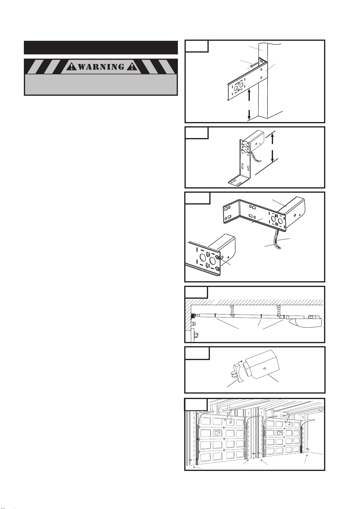
8-12. INSTALL PHOTO EYE SAFETY SYSTEM
To provide the maximum protection install the photo eye
sensors so beam is NO HIGHER than 6” (150mm).
Fig. 31
Wall Stud
1/4” x 1-1/2”
Lag Screws
Mounting Bracket
MOUNTING THE PHOTO EYE SENSOR BRACKETS TO WALL:
Locate the mounting position for photo eye brackets 3.5” to 5”
(90-125mm) from floor level.
After mounting, the photo eye beam must have a clear path
from one side of the door to the other.
Use the bracket mounting holes as a template to locate an drill (2)
3/16" diameter pilot holes on both sides of the garage door as shown
in Fig. 31.
Secure the bracket with 1/4" x 1-1/2" lag screws provided as shown
in Fig. 31.
Note: If needed use extension brackets (see accessories page 33).
MOUNTING THE PHOTO EYE SENSORS TO MOUNTING
BRACKET. Fig. 32
Install the sensors to the mounting bracket by inserting bend
clips of sensor bracket through the vertical slot on mounting
bracket.
Insert straight clips through other set of vertical slot on the mounting
bracket.
Twist one of the straight clips slightly to lock the sensor in place
once inserted through vertical slot on the mounting bracket.
Repeat the above procedure for the other sensor.
ROUTE WIRES Fig. 33
Route wires along wall use staples (not provided) to secure
wiring to wall. Do NOT punch wire. Drive staples with only
enough force to hold wiring in place.
Be sure the wiring is routed away from all moving parts of
door and rail.
Run wires along the top of the rail assembly and secure
them in wire holders.
SENSOR PROTECTION Fig. 34
Before performing maintenance work in garage, such as,
power washing, painting, and other tasks; protect sensors
with provided sensor caps.
DUAL DOOR INSTALLATION Fig. 35
In dual door installations, the transmitter (TX) and the receiver
(RX) photo eye sensors (as marked on each of the photo eye
components) should be mounted as indicate in Fig. 35. TX
and RX marks located on the back side of the transmitter
and receiver.
Fig. 31A
Fig. 32
Fig. 33
Fig. 34
3.5” to 5” (90-125mm)
from floor
5.5” (140mm)
Mounting
on garage
floor
Sensor Bracket
Mounting Bracket
To Terminal 2
To Terminal 1
Twist Clip
Wire Holder
Sensor Cap Protector
Photo Eye Sensor
Fig. 35
Receiver
Transmitter
Transmitter
Receiver
15
Page 18
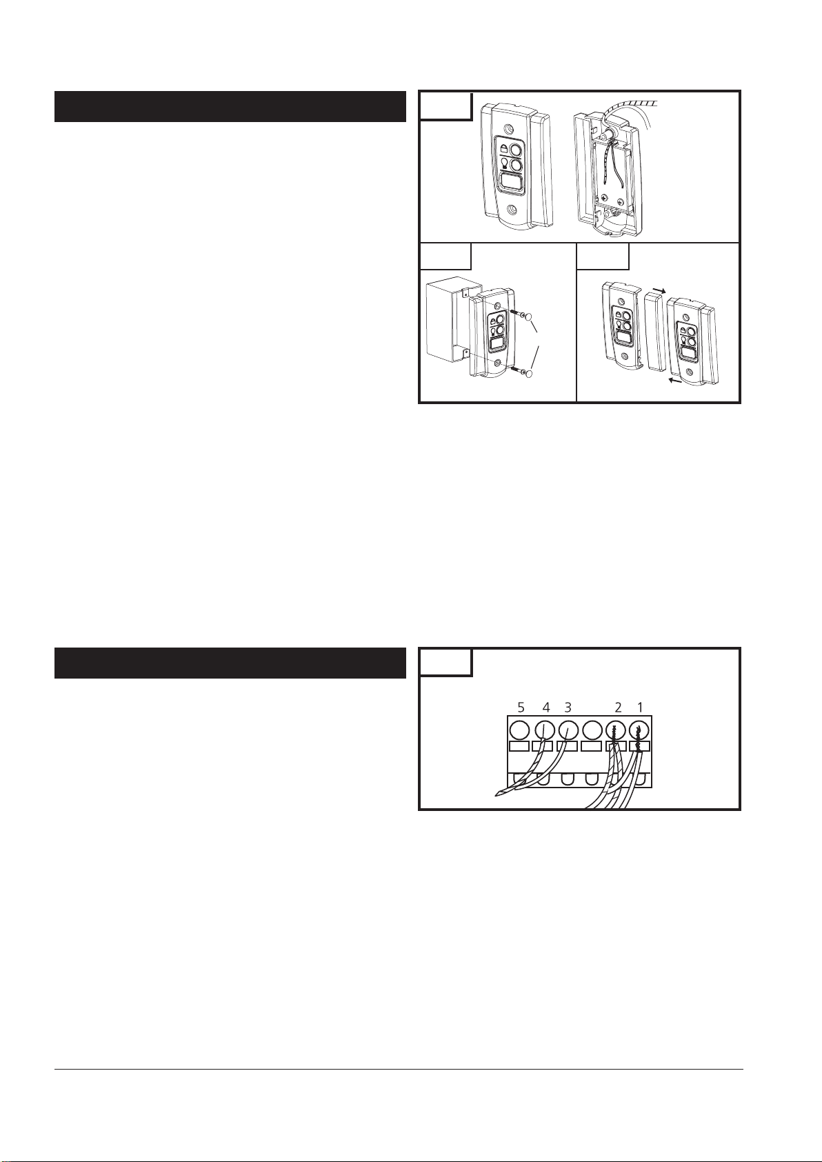
8-13. INSTALL WALL CONTROL PANEL
Fig. 36
To Terminal #4 Screw
The control panel must be mounted inside the garage within sight
of the garage door, clear of all moving garage door parts or any
associated parts - and at least 5 feet (1.5m) above the floor to
prevent the use of these controls by children. The device should
only be used when the door is in clear sight of the user and the
door area is free of people or any obstructions.
Attach 2-conductor wire to the screw terminal on back of
control panel. See Fig. 36 (Back). White wire attaches to
terminal #3 screw, white wire with color stripes attaches to
terminal #4 screw.
Position wall control panel onto wall in desired location.
Mark hole location on wall.
Drill 1/16” pilot holes into wall.
Insert and tighten screws to secure control panel to wall.
Make sure wiring is routed out from behind control through
one of the cutouts to avoid pinching the wires.
Route wires along wall use staples (provided) to secure
wiring to wall. Do NOT punch wire. Drive staples with only
enough force to hold wiring in place.
If mounting to drywall instead of wood, drill 3/16” pilot holes and
use anchors provided. If mounting to electrical box that is prewired
for this purpose, mount directly to box with proper screws provided.
See Fig. 36A.
Multiple Wall Control (Fig. 36B):
Wall control design provides a modular assembly of multiple
wall controls.
Each wall control must be connected to a designated garage
door opener, only one wall control per operator.
Detach wall control’s right side panel(s).
Attach wiring to back on each wall control (white wires to
terminal #3 screws, wires with stripes to terminal #4 screws).
Assemble wall control module and secure to the wall.
Complete installation as outlined above in step 1 and 2 for each
wall control.
Fig. 36A
Screw caps
4
Fig. 36B
To Terminal #3 Screw
3
8-14. CONNECTING WIRES TO OPERATOR
Separate the double wire from each photo eye into two single
wires: the white wire and the white wire with red stripes.
Combine the white wires from each photo eye and twist
stripped ends together tightly.
Insert stripped end of white wire combination into terminal
block hole #1.
Repeat procedure for the white wires with red stripes except
insert them into terminal hole #2.
Separate the double wire from wall control into two single
wires: the white wire and the white wire with black stripes.
Insert stripped end of white wire into terminal block hole #3.
Insert stripped end of white wire with black stripes into terminal
block hole #4.
Connect terminal block with attached wires to control unit,
see Fig. 37, 40.
For reference see wiring diagram Fig. 41.
Fig. 37
16
Page 19
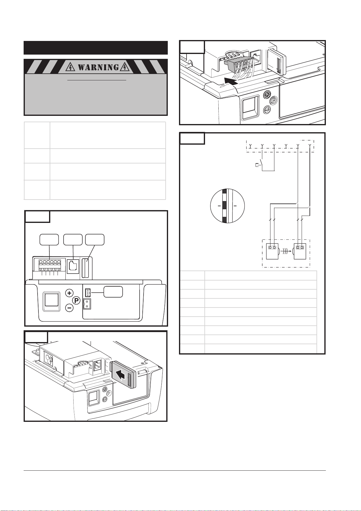
9. CONTROL UNIT CONNECTIONS
12
Danger of electric shock:
Before any wiring work begin, make sure that the
operator and all wiring is disconnected from the power
supply. During wiring make sure all wires remain disconnected from the power supply at all times.
Fig. 40
3.3.3
Terminal block XB03
XB03 Connection for
– Wall Control
– Photo eyes
XB72 Connection for modular antenna
XW40
XW81 Connection for expansion
Connection for MS bus expansion module
inputs / outputs
Fig. 38
XB03 XW40 XB72
5
4
3 2
1
XW81
Fig. 39
Modular Antenna Installation or Replacement
Fig. 41
3.3.3
- X B0 3
Wiring Diagram
for XB03 Terminal Block
- W 1
- W 2
21
Conductors/wires
AP27 Photo eye safety system
RX Photo eye receiver
TX Photo eye transmitter
1 Photo eye - Conductor 1
2 Photo eye - Conductor 2
Sb1 Impulse button - Wall Control
3
4
5
Wall controI - Impulse - Conductor 1
Wall controI - GROUND - Conductor 2
24 V DC
5
- S b1 2
- A P2 7
3
4
1
- W 1
1
2
2 1 1TX2
- W 2
1
2
RX
17
Page 20
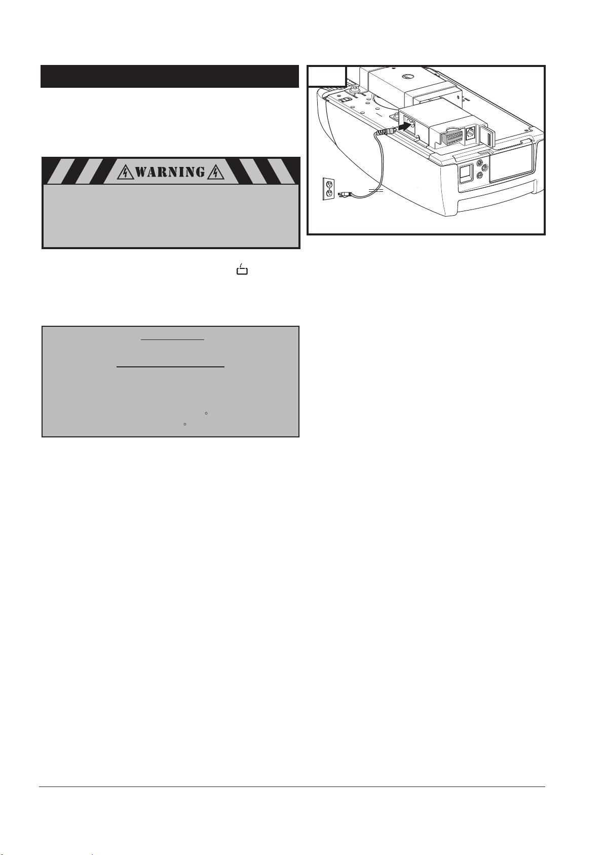
10. CONNECT TO POWER
To reduce the risk of electric shock, your opener is provided with
an insulated power cord with a 3-prong grounding plug. The cord
must be connected to a standard grounding outlet. If there is no
outlet available at the location, you must have a qualified
electrician install an approved grounded outlet in this area.
To prevent electrocution or fire, installation and wiring
must be done in accordance with local electrical and
building codes. DO NOT use an extension cord. DO NOT
use a 3 to 2 plug adapter. DO NOT modify or cut off the
grounding pin on the plug.
Plug the operator into a properly grounded outlet (Fig. 42).
The display will illuminate the word “On” and will be
displayed. This indicates that the operator is ready for set up.
See fig. 43A for additional display icons.
DO NOT operate or run the opener at this time.
IMPORTANT:
Contact Marantec America for
Replacement Power Cord
Part #105475
Model: YP-12/YC-12
Overall length 6ft.
UL/CSA Recognized
UL Type: E241374: SJT 3/C 18AWG 105 C 300V VW-1
CSA 177323: SJT 3/C 18AWG 105 C 300V FT2
Fig. 42
18
Page 21
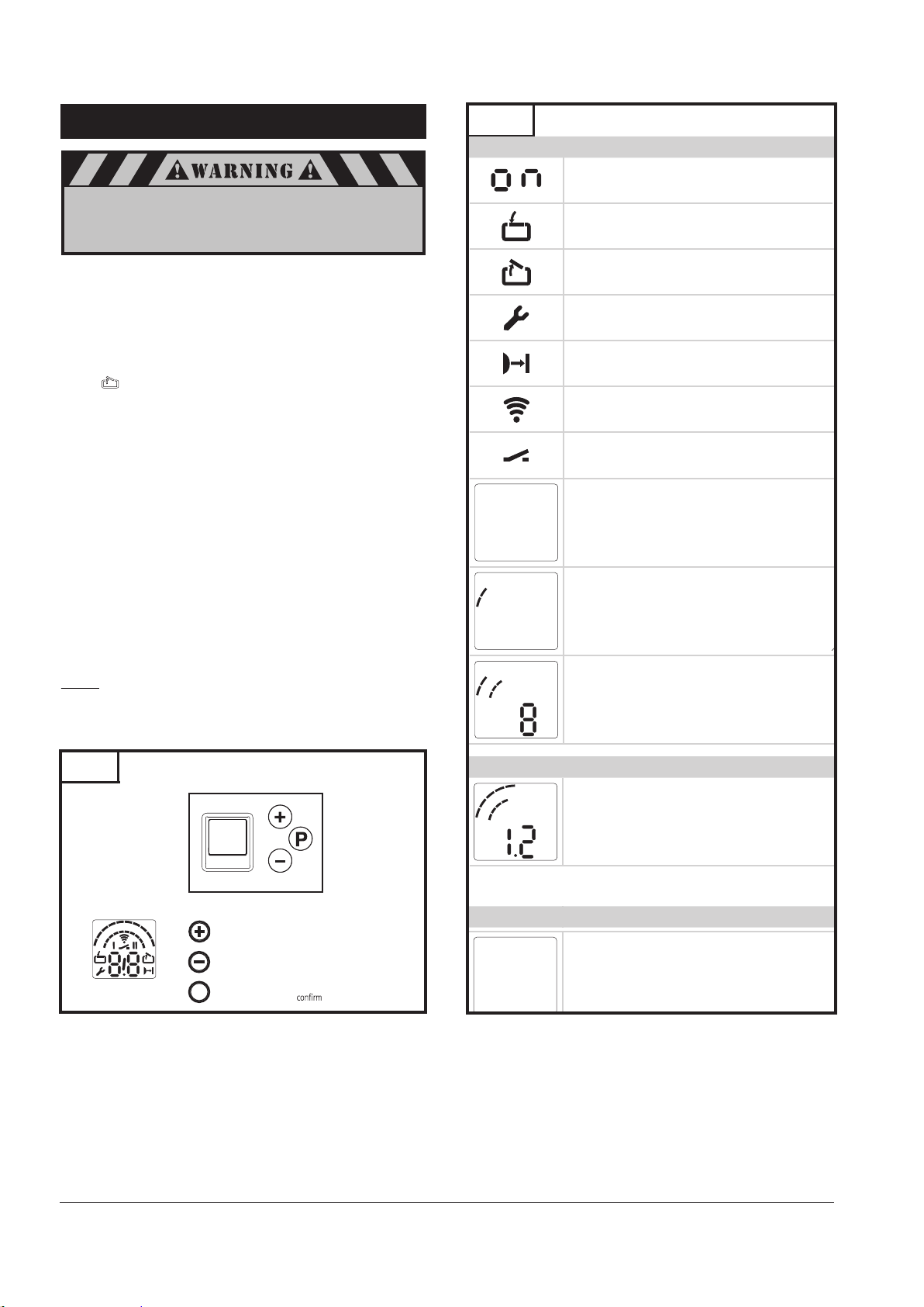
11. SYSTEM SET UP
1
2
3
4
5
6
7
8
9
0
In order to insure a trouble-free programming:
• The door must be in the “CLOSED” position and engaged
to the drive system (rail) before programming the
operator or a system reset is performed.
For proper initial operation of the operator, two basic
functions must be set using the initial system programming:
Open Door Position
Close Door Position
Program Remote Control (Transmitter)
Press and hold the “P” button for approximately 3 seconds.
When illuminates, release the button. You are now
ready to set or change the desired adjustment. If no buttons
are pressed within 120 seconds while in programming
mode, the control unit reverts back to operating mode.
TO MAKE OR CHANGE ANY ADJUSTMENT
If no changes are needed at any particular stage, you can keep
the current information and “skip” over a specific adjustment by
pressing the “P” button once. This is useful to know if you want
to change only one setting, without changing any of the other
adjustments. Simply enter the adjustment mode by pressing and
holding the “P” button for approximately 2 seconds, then press
and release “P” repeatedly until your particular adjustment is
reached. This bypasses the unneeded adjustments, and takes you
right to the adjustment you want. When your adjustment or
setting is complete, simply press ”P” as many times as needed to
bypass the remaining steps and exit out of the program,
returning the operator to normal mode.
NOTE: You may exit the System Set Up at any time by pressing
the button “P” for more then 5 sec. The set up programming
can be terminated at any time and from any stage. To do so,
press the “P” button for longer than 5 seconds.
Fig. 43A
Display Description
Ready for operation
Door position: CLOSED
Door position: OPEN
Fault message / Maintenance indicator in CLOSED
door position
Photoeye safety system
Remote control
External button
3
6
5
7
4
3
2
1
6
5
7
4
3
2
1
Status display
Battery backup system connected
8
9
Level indicator
0
Display shows Level 2
8
9
0
Menu and parameter indicator
(Displayed Menu 3, Parameter Setting 8)
Fig. 43
Overview of the control unit
Minute indicator
6
5
7
4
8
3
2
1
9
0
Times exceeding one minute are shown in
minutes and seconds.
Example: 1.2 = 1 minute + 20 seconds =
80 seconds
Status display
Control elements
6
5
7
4
8
3
9
2
0
1
LED display
Drive the door in the OPEN direction, increase the
value
Drive the door in the CLOSE direction, decrease
the value
P
Start programming, and save values
Display Function / Element
4
Warning time indicator (only for programmed
automatic closing)
19
Page 22
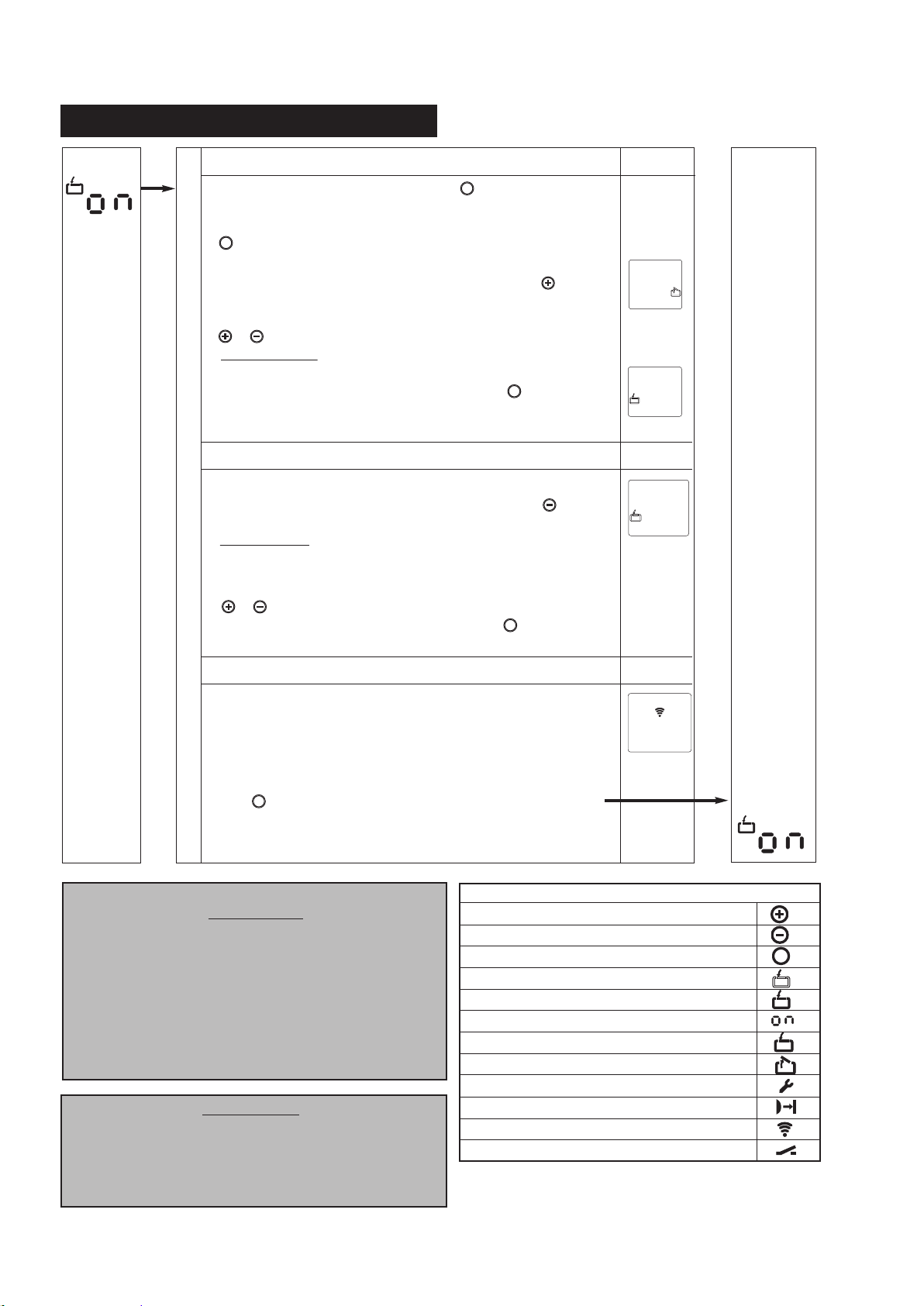
11. SYSTEM SET UP (cont’d)
System initial
display on
control panel
screen upon
power ON
System set up start and program open door travel position
1
To start the system set up, press and hold the button for approximately
5 seconds.
Once the display timer counter reaches the count of 5, release the
P
button.
P
The blinking open door icon is displayed on the control panel screen.
Set the open door travel postion by pressing and holding the
button until the door reaches the desired open travel position.
Further fine tuning of the open position can be performed by using the
or buttons.
Important Note: The back of the trolley must be approximately
half inch from the reference bumper on rail.
Once the desired open travel position is reached, press button to save
P
open travel position and move to the next step in the system set up.
Program close door travel position
2
The blinking closed door icon is displayed on the control panel screen.
Set the close door travel position by pressing and holding the button
until the door reaches the down travel postion desired.
Important Note: In order to avoid unintentional door reversal, DO NOT
set the down travel position too close to the floor where the door
rubber seal is completely squeezed/compressed against the ground.
Further fine tuning of the close travel position can be performed by using the
or buttons.
Once the desired close travel position is reached press button to save
P
the close travel position and move to the next step in the system set up.
3
Program a remote control (transmitter)
Control Panel
Display
The transmission icon will blink on the control panel display.
This indicates the operator is ready to learn the remote control code.
Press and hold the button on the remote control that you wish to use.
The transmission icon will change its displayed symbol to a solid icon.
This indicates that the remote control code has been successfully learned by operator.
Release the remote control button.
P
Press button to save remote control code and end the system set up.
NORMAL OPERATION
IMPORTANT:
On the first open travel activation, the trolley will make
contact with and will rest against the rail bumper.
This will appear as if the system (door) went past the
set open travel limit. However, this is not the case.
On the next open travel cycle, the system will
recognize the program travel limit.
Every 20 cycles the operator will perform a travel limit
check and it will function as described on
“Normal Operation” note.
IMPORTANT:
Upon completion of the initial set up, the operator
must be cycled for two complete cycles
(complete cycle comprises of one uninterrupted up
activation of the system and one uninterrupted down
activation of the system).
System display
on control panel
screen after setup is completed.
Legend:
Drive the door in the OPEN direction, increase the value
Drive the door in the CLOSE direction, decrease the value
Start programming, comfirm and save values
The display flashes
Display lights up
Ready for operation
Door position: CLOSED
Door position: OPEN
Fault message/Maintenance indicator in CLOSED door position
Photoeye safety system or closing edge safety device
Remote control
External button
P
20
Page 23
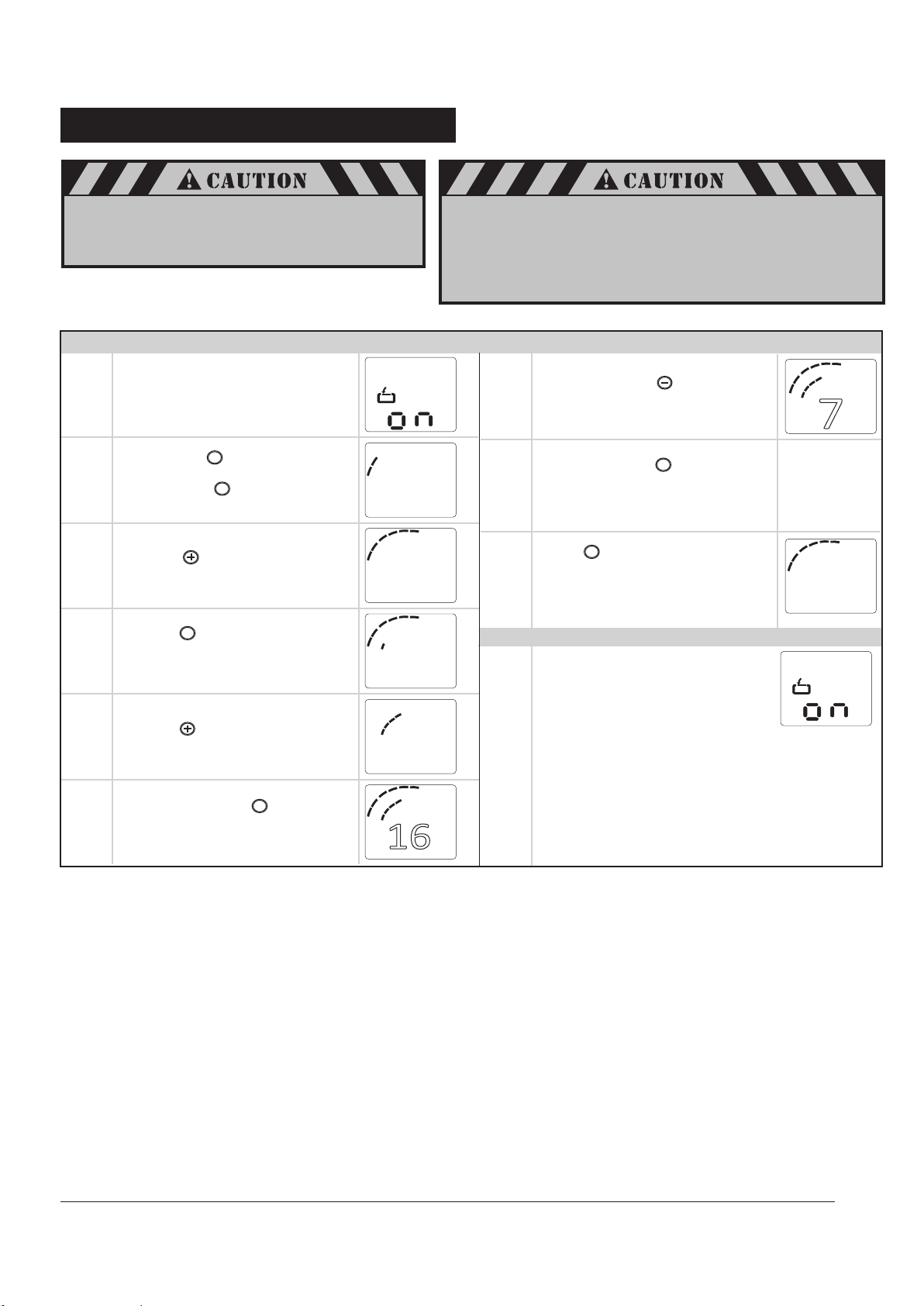
12. ADVANCED SETTINGS
Additional operator functions can be set using the
advanced operator functions. Parameters factory
default settings can be restored. This programming may
only be carried out by a professional installer.
Advanced Settings Programming Procedure (Diagram Illustrates Setting of Level 6, Menu 4)
Door should be in closed position.
1.
2.
The control system operating mode
will be displayed as shown.
Press and hold button until
counter passes number “10”.
Then release the button.
P
P
4
3
2
1
After a system reset, all parameters are restored to the factory settings.
• All the required function in the initial set up and advanced
re-programmed if it is required.
• The operator must be activated for two (2) complete uninterrupted
cycles in order for all restored or operating parameters settings to be
learned by the operator again.
Press and release to change
7.
screen display.
Number “7” will blink.
6
5
7
8
9
0
8.
Press and release .
Save parameter setting.
P
Screen display as shown.
6
5
7
4
8
3.
4.
5.
Press to select Level 6.
Screen display as shown.
P
Press . Menu 1 will appear on
display as shown.
Press to select Menu 4
(reset menu).
Screen will display “16” as shown.
3
2
1
3
2
1
16
3
2
1
16
9
0
6
5
7
4
8
9
9.
10.
6
5
7
4
8
9
0
P
Press for 5 seconds to exit
advanced settings set up.
OR
Repeat steps 2-8 to change
other Menu parameters
settings must be
6
5
7
4
8
3
2
1
9
0
6
5
7
4
8
3
2
1
9
0
Press and release .
6.
Number “16” blinks.
Note: Level 3 is disable
6
5
7
4
8
P
3
2
1
9
0
21
Page 24
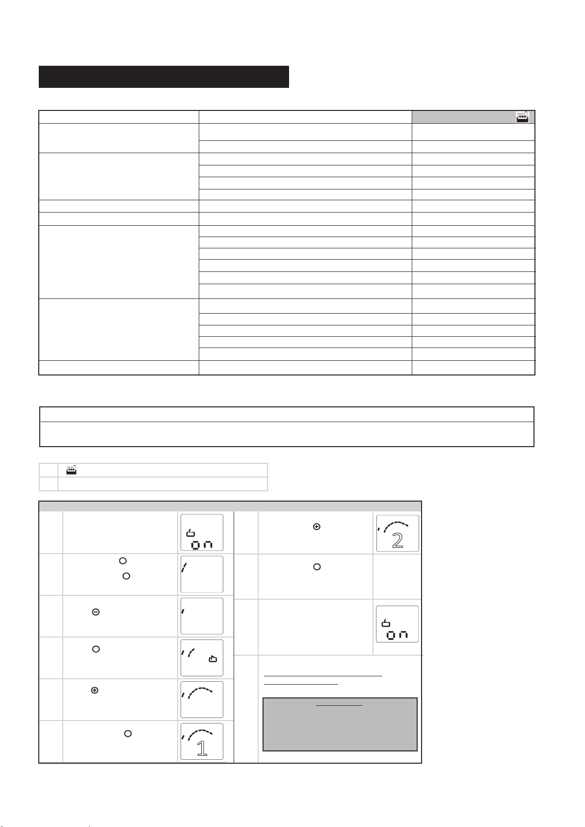
12. ADVANCED SETTINGS (cont’d)
General overview of the programmable functions
Level Menu Factory default setting ( )
Level 1 – Basic function
Level 2 – Operator settings
Level 4 – Transmitter Additional Functions
Level 5
Level 6 – Variable speed
Level 7 – Maintenance and servicing
Level 8
Menu 3: Intermediate “OPEN Position”
Menu 8: RESET
Menu 1: “OPEN” position – operator (system) force
Menu 2: “CLOSE” position – operator (system) force Setting 8
Menu 3: “OPEN” position – operator sensitivity Setting 10
Menu 4: “CLOSE” position – operator sensitivity
Menu 2: “Intermediate “OPEN Position”
Menu 4: Light timer
Menu 1: OPEN speed
Menu 2: Soft run OPEN speed
Menu 3: Soft run OPEN position
Menu 4: CLOSE speed
Menu 6: Soft run CLOSE speed
Menu 8: Soft run CLOSE position
Menu 1: Door cycle counter
Menu 2: Servicing counter
Menu 3: Servicing interval
Menu 8: Reset maintenance and servicing
Menu 9: Fault indicator
Menu 7: Force relief CLOSED door position Setting 1 - Not Active
Setting 8
Setting 10
Setting 4.1 (255 sec)
Setting 16
Setting 7
Setting 16
Setting 7
Level 1: Basic Functions
Menu 3: Intermediate OPEN Position
The closing function with automatic closing is possible. Only the intermediate position that was programmed last can be used.
Menu 8: System RESET
1 No reset
2 Reset system settings
Reset Procedure
1.
2.
3.
4.
5.
6.
Door should be in closed position.
The control system operating mode
will be displayed as shown.
P
P
P
Press and hold button until
counter passes number “10”.
Then release the button.
Screen display as shown.
Press to select Level 1.
Screen display as shown.
Press . Menu 3 will appear on
display as shown.
Press to select Menu 8
(reset menu).
Screen will display “1” as shown.
P
Press and release .
Number “1” blinks.
3
2
1
3
2
1
3
2
1
3
2
1
3
2
1
6
5
4
6
5
4
6
5
4
1/2
6
5
4
1
6
5
4
Set using the (+ / OPEN) and (- / CLOSE) buttons
Press and release to change
7.
screen display.
Number “2” will blink.
7
8
9
0
Press and release to reset operator.
8.
During reset the display screen will turn
P
blank for a couple of seconds.
7
8
9
0
7
8
9
7
8
9
0
7
8
9
0
Upon completion of operator reset,
the LCD display illuminates.
9.
Stand-by mode is displayed
as shown.
10.
The operator must be set-up again as
described in Section 11.
IMPORTANT:
Upon completion of the initial set up, the
operator must be cycled for two complete cycles
(complete cycle comprises of one uninterrupted
up activation of the system and one uninter-
rupted down activation of the system).
6
5
7
4
8
3
9
2
0
1
22
Page 25
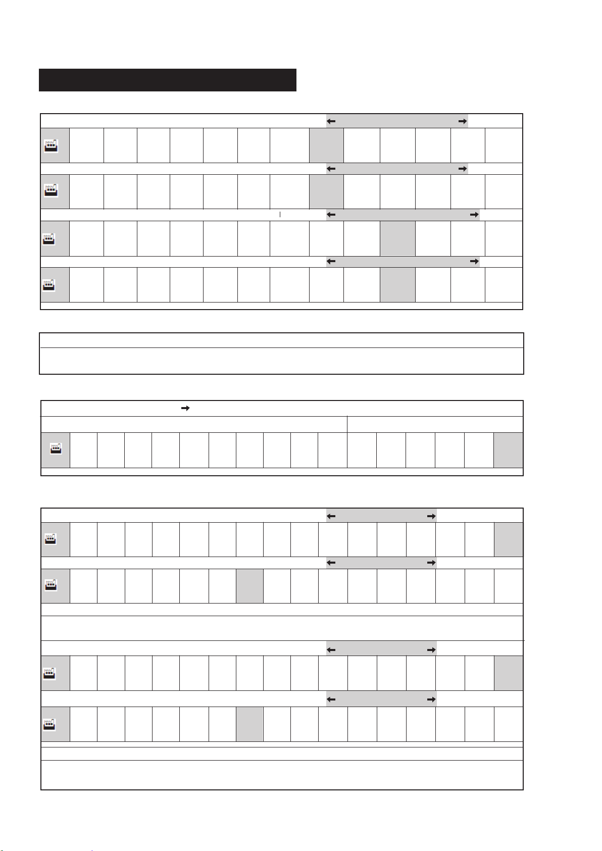
12. ADVANCED SETTINGS (cont’d)
Level 2: Operator settings
Menu 1: “OPEN” position operator (system) operating force Lower Force Higher Force
1 2 3 4 5 6 7 8 9 10 11 12 13
8
Menu 2: “CLOSE” position operator (system) operating force Lower Force Higher Force
1 2 3 4 5 6 7 8 9 10 11 12 13
8
Menu 3: “OPEN” position operator sensitivity More Sensitive Less sensitive
10
OFF
2 3 4 5 6 7 8 9 10 11 12 13
Menu 4: “CLOSE” position operator sensitivity More Sensitive Less sensitive
10
OFF
2 3 4 5 6 7 8 9 10 11 12 13
Level 4: Transmitter Additional Functions
Menu 2: Intermediate OPEN Position
The closing function with automatic closing is possible. Only the intermediate position that was programmed last can be used.
Set using the (+ / OPEN) and (- / CLOSE) buttons
Level 5: Functions overview
Menu 4: Operator Light “ON”
Timer (in seconds) Timer (in minutes)
5 10 15 20 25 30 35 40 50
2
1.2 1.4 2.0 2.3 3.0 4.1
(80sec) (100sec) (120sec)
(150sec) (180sec) (255sec)
Level 6: Variable Speed
Menu 1: OPEN speed
Slower Faster
16
- - - -
5 6 7
Menu 2: Soft run OPEN speed
1 2 3 4 5 6
7
Menu 3: Soft run OPEN position
Set using the (+ / OPEN) and (- / CLOSE) buttons
Menu 4: CLOSE speed
- - - - 5 6 7 8 9 10 11 12 13 14 15 16- - - -
16
5 6 7 8 9 10 11 12 13 14 15 16
Menu 6: Soft run CLOSE speed
1 2 3 4 5 6 7
7
Menu 8: Soft run CLOSE position
Set using the (+ / OPEN) and (- / CLOSE) buttons
8 9 10 11 12 13 14 15 16
Slower Faster
7
- - -- - - - -- --
- --
Slower Faster
Slower Faster
- - - -- -
- --
23
Page 26
12. ADVANCED SETTINGS (cont’d)
Level 7 – Maintenance and servicing
Menu 1: Door cycle counter
indicator showing the number of complete
Once the counter setting is reached, it restarts count again.
cycles, up to 999999.
Menu 2: Servicing counter
indicator showing the number of complete cycles left up to maintenance indication.
Figures shown one after the other up to the indicator
point, then repeated.
Menu 3: Service/Maintenance Counter Setting
completed before a servicing reminder is displayed.
Adjustment of the number of door operations to be
1 OFF Default
2 100 door operations
3 500 door operations
4 1,000 door operations
5 4,000 door operations
6 5,000 door operations
7 6,000 door operations
8 7,000 door operations
9 8,000 door operations
10 9,000 door operations
11 10,000 door operations
12 15,000 door operations
13 20,000 door operations
14 30,000 door operations
15 40,000 door operations
16 50,000 door operations
Menu 8: Reset maintenance and servicing
The fault log for maintenance, diagnostics and servicing
work is reset here.
Menu 9: Fault indicator
Shows the current fault message.
(No more than 16 fault messages can be viewed).
1 No Reset - Default Setting
2 Reset the fault log
Display the previous fault /
Navigate through the list of faults
Navigate through the list of faults
Level 8 - CLOSE Travel Position Pressure Sensitivity Adjustment (PSATM)
1 Default not activated
2
Short
Medium
3
Long
4
24
Page 27
13. REMOTE CONTROLS
14. TRANSMITTERS
Danger of injury due to uncontrolled operation of the door!
• Operate the controls or the hand transmitter only when there
are no persons or objects in the path of the door.
• Ensure that the controls and the hand transmitter are never
used by children or unauthorized persons.
• Ensure that the hand transmitter cannot be operated by
accident (in a trouser pocket, for example).
FCC Certified: This device complies with Part 15 of the FCC rules. Operation is subject to the following
two conditions: (1) this device may not cause harmful interference, and (2) this device must accept any
13-1. TRANSMITTER
14. TRANSMITTERS
A family of state-of-the-art transmitters, each transmitter is custom
encoded with installed battery. Offered in two styles to suit your
interference received, including interference that may cause undesired operation.
Changes or modifications not expressly approved by the party responsible
for compliance could void the user’s authority to operate the equipment.
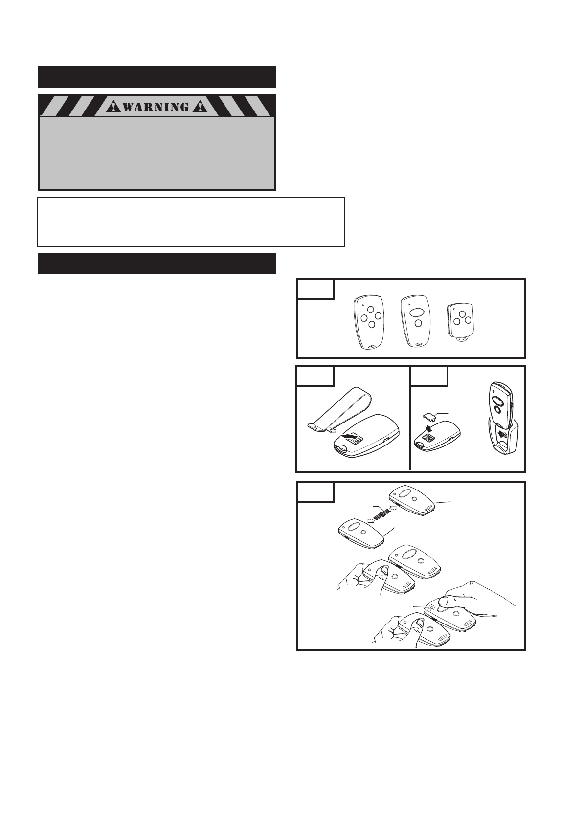
Fig. 44
personal preference. See Fig. 44.
Mini (2-or 4-channel)
Micro (3-channel) with keyring attachment.
TRANSMITTER MOUNTING:
The transmitters can be conveniently mounted inside your
car using the visor clip or on the wall using the mounting plate.
Visor Clip (Fig. 45)
Snap visor clip into transmitter.
Fig. 45
Affix assembly to visor.
NOTE: If you do not need the visor clip, install the visor
compartment cover.
Mounting Plate (Fig. 45A)
Secure the mounting plate to area of preference using screw
and anchor.
Snap the visor compartment cover.
Slide the transmitter into the mounting plate, which will hold
it firmly in place.
MULTIPLE TRANSMITTERS (Fig. 46):
Fig. 46
Each transmitter comes factory programmed with random codes.
2-channel transmitters have 2 different random codes, one per
button, 3-channel transmitters have 3 different random codes and
4-channel transmitters have 4 different random codes, one per
button. Transmitters that are purchased separately as accessories
have random codes that must be changed in order to match the
code of the “active” transmitter, which you are already using.
Below are instructions for transferring an active code from a
button on one transmitter to a button of your choice on another
transmitter.
Connect the transmitter with active code to the new
transmitter using the programming connector. (Fig 46)
Press and hold the selected channel button on the transmitter
with the active code.
Press and hold the respective channel button on the new
transmitter. The light in the transmitter initially starts
blinking and then illuminates continuously after 1-2 sec.
Code transfer is completed.
Programming connector can be removed and both
transmitters can now be used to operate the same opener.
NOTE: For multi-button transmitters, be sure to carry out this
procedure for all the buttons you desire to use.
Programming
Connector
Visor Clip
Transmitter with
active Code
Light blinks
Fig. 45A
Visor
Compartment
Cover
New Transmitter
25
Page 28
13-1. TRANSMITTER (cont’d)
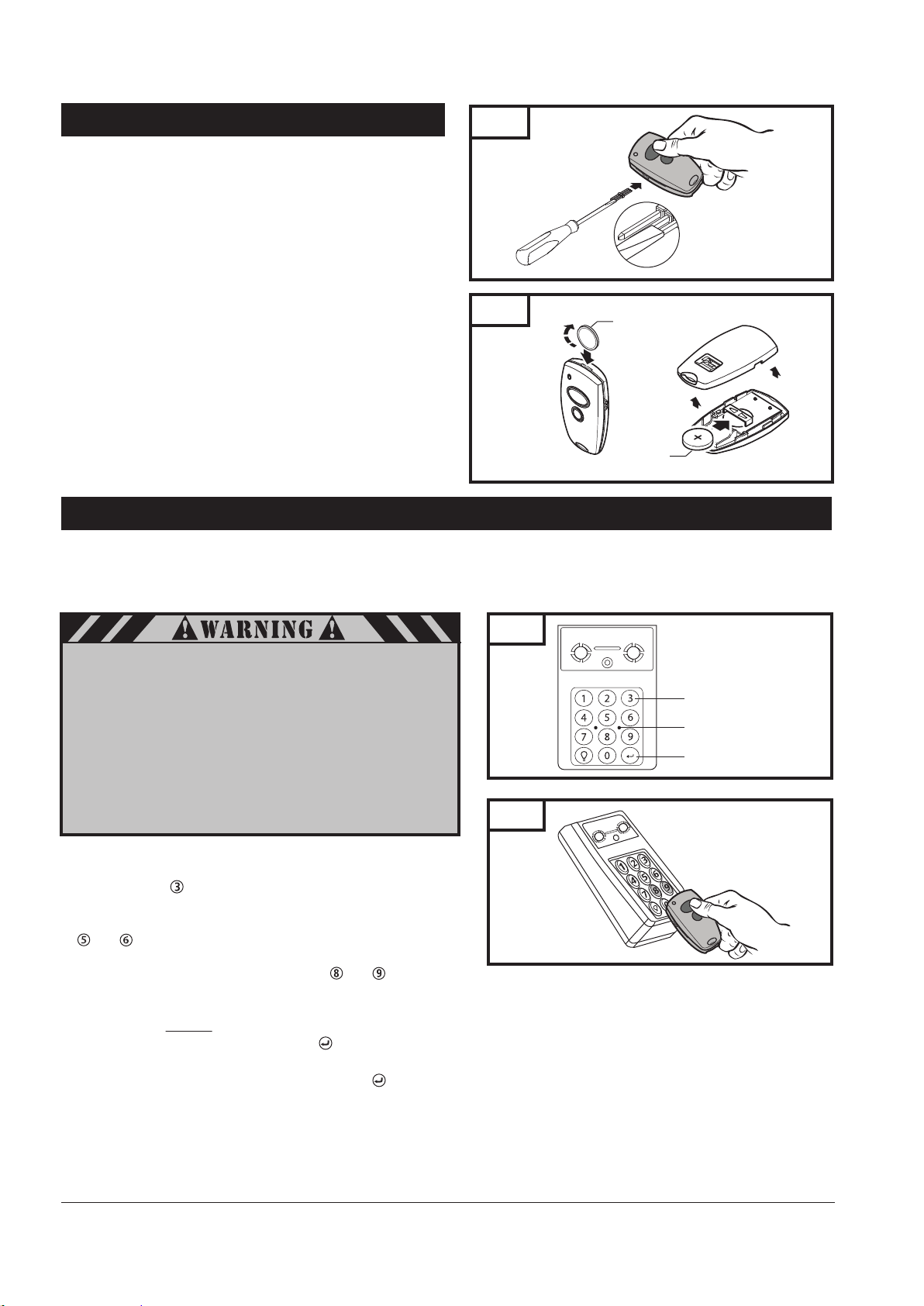
Fig. 47
CHANGING THE CODE (Fig. 47):
The transmitter factory preset code can be changed as follows:
Insert the programming connector into transmitter terminal.
Short one of the outer pins of the programming connector
with the middle pin.
Press and hold the respective channel button. The light will
blink rapidly for approximately 5 sec. Release the button after
the light illuminates continuously. Code will change in
approximately 2 seconds.
Remove the programming connector.
Once the transmitter code is changed, the operator must be
Fig. 48
Coin
recoded with the new transmitter code as described on the
initial system set up page 19.
NOTE: For multi-button transmitters, be sure to carry out this
procedure for all the buttons you desire to use.
BATTERY REPLACEMENT (Fig. 48):
Open the transmitter by using small coin.
Insert a 3V battery (type CR2032) as shown.
Battery
Close the transmitter.
NOTE: Replace batteries with same type only.
13-2. WIRELESS KEYLESS ENTRY SYSTEM (OPTIONAL ACCESSORY)
The Wireless Keyless Entry System offers you the convenience of opening and closing your garage door by entering your own 4-digit
Personal Identification Number (PIN) via the keypad. The WKE can be programmed wireless to control up to 4 garage door operators that
each work on a different code, or to control one garage door operator with up to 4 different PINs. You can also program it to allow a
temporary PIN of your choice to be stored, to provide temporary access to authorized visitors or service persons.
To prevent possible SERIOUS INJURY or DEATH from a moving
garage door:
Install Wireless Keyless Entry System within sight of the garage
•
door, out of reach of children at a minimum height of 5 feet (1.5m)
and away from ALL moving parts of the door.
•
ALWAYS keep remote controls out of reach of children. NEVER
permit children to operate, or play with remote controls.
Activate door ONLY when it can be seen clearly, is properly
•
adjusted, and there are no obstructions to door travel.
•
ALWAYS keep garage door in sight until completely closed.
NEVER permit anyone to cross path of moving door.
PROGRAM PIN AND TRANSFER CODE
Installl batteries provided in WKE, Fig. 50.
Press and hold button for at least 3 seconds to activate
programming mode, LED’s light up for 10 seconds.
Immediately, aim the top of transmitter very close to buttons
and .
Press and hold button you use to operate the door and move
transmitter slowly down toward the number and button area.
Release transmitter button when LED’s on keypad flash.
Immediately, enter a 4-digit personal identification number (PIN)
of your choice # # # #.
Immediately, press and release the ENTER button. LED’s and keypad
buttons will light up for 2 seconds signaling programming is completed.
Test WKE by entering the PIN, then press ENTER button.
NOTE: To program the WKE to more than one garage door
operator (maximum 4), repeat the steps above using a new
PIN for each additional garage door operator.
Fig. 49
Progamming Buttons
LED (Indicator Lights)
ENTER Button
Fig. 50
26
Page 29
13-2. WIRELESS KEYLESS ENTRY SYSTEM (cont’d)
CHANGE AN EXISTING PIN
Press button for at least 3 seconds, LED’s will flash slowly.
Release button.
Enter the programmed PIN that you want to change.
Press the ENTER button. LED’s will flash rapidly.
Enter the new 4-digit PIN of your choice # # # # then press the
ENTER button. LED’s and keypad light up for 2 seconds.
To test WKE, enter the new PIN then press the ENTER button.
The garage door opener will activate.
PROGRAM A TEMPORARY PIN
A temporary 4-digit PIN can be programmed to allow access to visitors.
Each programmed PIN can program one temporary PIN. The temporary
PIN can be set for a number of door openings (max 99). The temporary
PIN cannot be the same as any previously programmed PIN.
Press button for at least 3 seconds.
LED’s will flash slowly for 10 seconds.
NOTE: To successfully establish a temporary pin, steps 2-4 must be
completed within 10 seconds after programming activation.
Enter any programmed PIN, then press ENTER button.
LED’s will flash rapidly.
Enter the temporary 4-digit PIN of your choice # # # # then press
the ENTER button. LED’s will flash very rapidly.
Press the number of openings the temporary PIN will work
(up to 99). Then press the ENTER button.
LED’s and key pad buttons light up for 2 seconds then
system goes in stand-by mode.
To test, enter the temporary PIN, then press the ENTER
button. The garage door operator will activate. If the
temporary PIN was set for a number of openings, the test
will use up one opening programmed PIN.
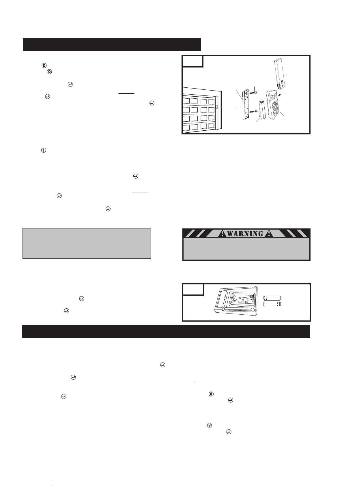
Fig. 51
Slider
Security
Screw 3x10
Wireless Keyless
Entry System
Mounting Plate
Mounting
Screw (2) 4x35
Battery Cover
INSTALLATION
Select a location to mount the Keyless Entry at a minimum
height of 5 feet (1.5m) out of the reach of children.
Use mounting plate as template, mark hole location
and then drill two 1/8 inch (3.2mm) pilot holes.
Secure plate to the mounting surface with the (2)
screws provided. Do not over-tighten screws to avoid
cracking the plastic.
Cover batteries with battery cover.
Snap WKE into the mounting plate and secure with
screw provided. See Fig. 51.
Install slide-up protective cover. Align cover slides with
slide grooves on WKE and slide cover down until it locks.
BATTERY
To prevent possible SERIOUS INJURY or DEATH:
NEVER allow small children near batteries.
If battery is swallowed, immediately notify doctor.
NOTE:
To clear the temporary PIN, repeat steps 1-3
above, setting the number of openings to “0” in step 4.
CLEARING WKE Memory
Remove Wireless Keyless from wall mounting plate.
Remove batteries from Wireless Keyless.
Press and hold ENTER button.
Install batteries back. Match polarity designation.
Release ENTER button, LED flash rapidly
approximately 5 seconds.
14. OPERATION OF YOUR OPERATOR
The garage door operator can be activated through the following
accessories:
WIRELESS KEYLESS ENTRY SYSTEM
The garage door operator activates when the PIN and ENTER
button are pressed. The keypad will blink for 28 seconds, during
that time the ENTER button can be used to stop, start,
reverse the door.
If the wrong number is accidentally pressed, press the correct PIN
then the ENTER button. The Keyless Entry will transmit only
the last four digits.
Low Battery Indicator:
Replace the batteries (AAA) when all the keypad buttons start to
flash (10 seconds) upon raising the Wireless Keyless protective cover.
Fig. 52
ONE-BUTTON-TO-CLOSE: The Keyless Entry has a feature that
allows the door to be closed using the ENTER button instead of a PIN.
NOTE: Factory setting-active.
To deactivate the one button close feature:
Press the button for 3 seconds. LED on keypad flash slowly.
Press the ENTER button.
The keypad LED’s light up for 2 seconds indicating that
the one button close feature has been deactivated.
To activate the one button close feature:
Press the button for 3 seconds. LED on keypad flash slowly.
Press the ENTER button.
The keypad LED’s light up for 2 seconds indicating that
the one button close feature has been activated.
27
Page 30
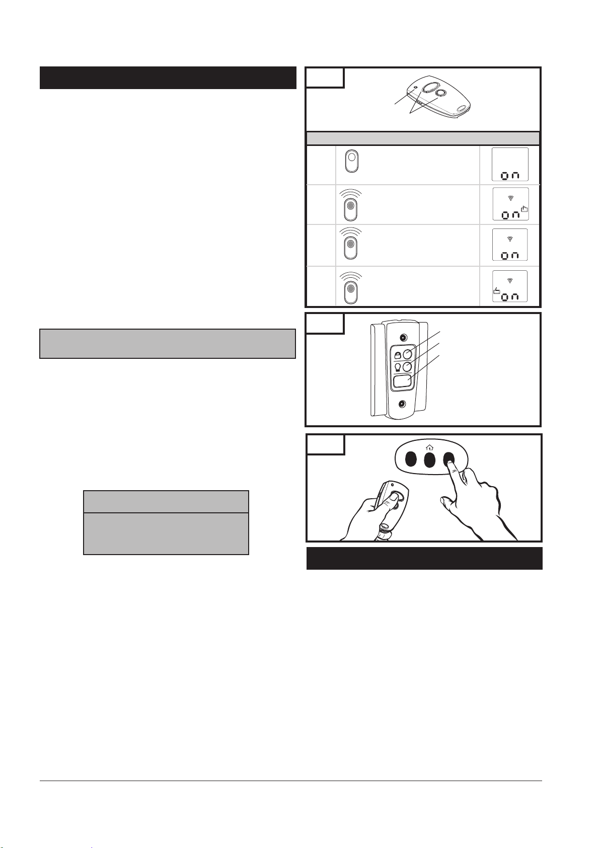
14. OPERATION OF YOUR OPERATOR (cont’d)
Fig. 53
REMOTE CONTROL TRANSMITTER:
To open or close garage door, press and hold designated button
(Transmitter has an indicator light that will illuminate). See Fig. 53.
When garage door begins to move, release button.
To stop garage door during travel, press and hold button until
door stops, then release button.
To resume garage door travel after stopping, press button
again. Door begins to move in the opposite direction.
WALL CONTROL PANEL:
The Door Pushbutton will light when Wall Control properly
connected (if it does not light up, review section 8-13
“Install Wall Control” on page 15.
To open or close garage door, press and hold Illuminated Door
Pushbutton. See Fig. 54. When garage door begins to move,
release button.
To stop garage door during travel, press and hold button until
door stops, then release button.
To resume garage door travel after stopping it, press button
again. Door begins to move in the opposite direction.
The Light On / Off button can be used to turn lights on or off.
NOTE: The operator light will dim down when
turned off.
When using the light On / Off button, the automatic timer is
ignored, and the lights will remain on until the button is pressed
again, or until the operator is activated and the automatic timer
begins again.
The Lock/Vacation button can be used to lock out all remote control
transmitters. The door can still be activated by wall control panel or
keyless entry system. Press and hold Lock/Vacation button for 2-3
seconds. Release button. Illuminated Door Pushbutton will flash
continuously while lock mode is active. To unlock opener, press and
hold Lock/Vacation button for 2-3 seconds.
Indicator Light
Buttons
Operating the door using a hand transmitter
1.
2.
3.
4.
Fig. 54
The control system is in
operating mode.
Impulse
The door moves in the
OPEN direction
Impulse
The operator system stops.
Impulse
The door moves in the opposite
direction (CLOSE direction).
Lock/Vacation Button
Light On/Off Button
Illuminated Door Pushbutton
Fig. 55
Important Note: If the vacation lock
mode is engaged.
By pressing and holding the door
activation button for one second or
longer will disengaged the vacation lock
mode.
OPERATOR LIGHT:
Light will come on whenever operator is activated.
The default factory setting for the light to stay “on” is 4
minutes and 15 sec., or until the Light On / Off button on the
wall control panel is pressed, whichever is sooner.
Light can be turned on and off manually as described under
operation of wall control panel.
Light will flash when the operator senses an obstruction either
detected by the internal safety system or the photo eye sensors.
To stop light from flashing, remove obstruction and operate
door normally. The fault light indicator will flash for the set
light time “on” factory default setting of 4 minutes
15 sec. maximum.
15. HOMELINK
Before you can use your car’s HomeLink
garage door you must transfer an active code from the
transmitter to the HomeLink
(Reference - HomeLink
Clear memory in HomeLink® transceiver per manufacturer
®
TRANSCEIVER
®
®
Universal transceiver.
®
Manual) (See Fig. 55)
device to open a
instructions.
Make sure the door path is clear and the door is in the line
of site at all time during the set up.
Start the programming sequence by pressing the
transmitter button and the HomeLink® transceiver button
on console simultaneously. Follow manufacturer
instructions to complete programing sequence. No learn
button on the operator is required to be pressed.
Repeat steps above for the other channels available.
28
Page 31
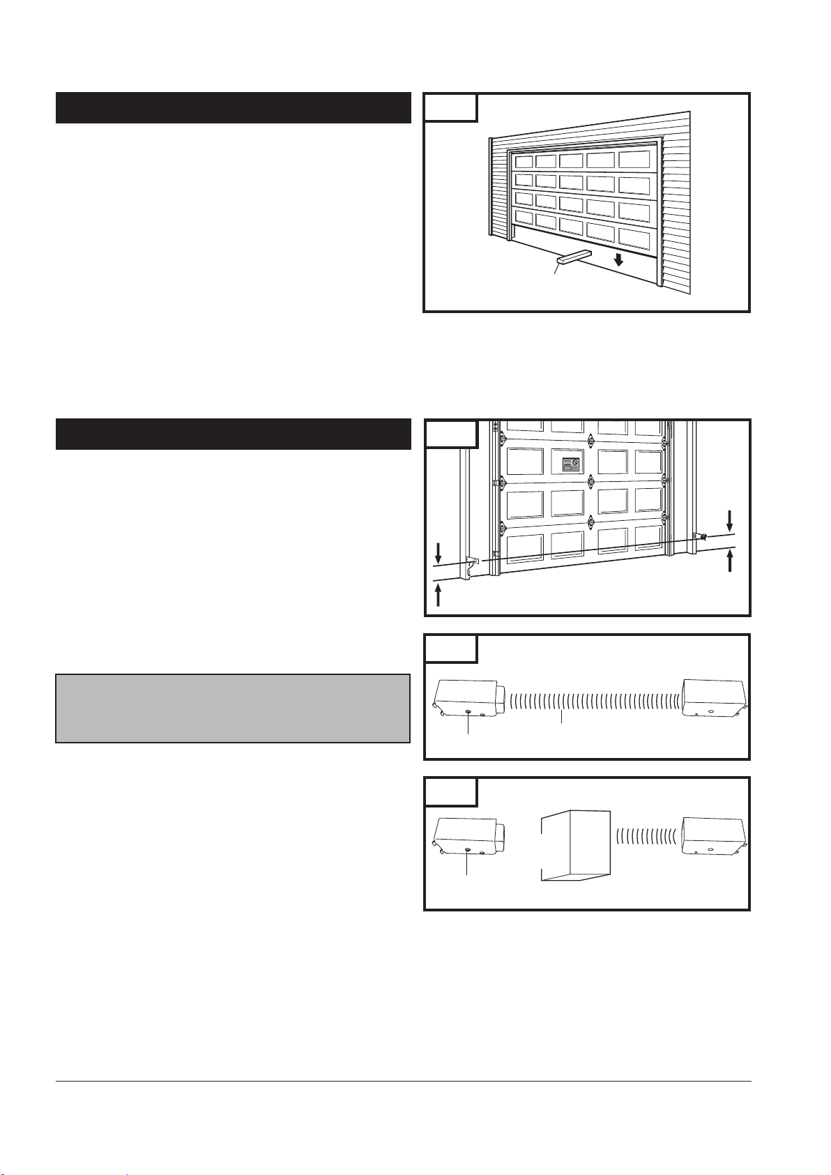
16. TEST SAFETY REVERSAL
The safety reversal function of your operator is an extremely
important feature of your operator. Testing this function ensures
the correct operation of your operator and door.
The reversal system test should be performed:
Once per month.
Anytime the travel or force limits are reset or changed.
Once the adjustments have been set and the door has been run
up and down twice to “learn” the new settings, you must test
the reversal system for proper operation.
Place a 1-1/2" (40mm) high rigid object (or a 2x4 board laid flat)
on the floor directly in the path of the door. See Fig. 56.
Start the door in the downward direction and watch what happens.
When door contacts the object (or 2x4), it should stop,
reverse, and automatically return to the fully opened position.
If the door does not reverse, reset the down travel limit
so that the door travels slightly further down in the closed
direction. Then, retest the unit as described above.
If the door still does not reverse, disconnect your operator
and call a service person.
Fig. 56
1-1/2” (40mm) high rigid object
17. ALIGN AND TEST PHOTO EYE SENSORS
PHOTO EYE SENSORS ALIGNMENT:
The photo eye sensors maintain an invisible, unbroken beam
between each other. See Fig. 57.
NOTE: Sensor alignment must be done with the door in the closed
position in order to ensure proper visibility of the sensor indicator
LED.
When the photo eye system is connected to the operator
and the power is on, the green light on the transmitter sensor
flashes, if the sensors are not aligned. When the sensors are
aligned, the green light on the transmitter sensor will turn
steady. See Fig. 58.
Sensors must be installed parallel to the door plane and make
sure the sensors are facing each other.
AFTER THE SENSORS HAVE BEEN PROPERLY ALIGNED.
MAKE SURE THAT THE SYSTEM OPERATION AND
SAFETY TESTS OUTLINED BY THE GARAGE DOOR
OPENER MANUFACTURER HAVE BEEN VERIFIED.
SAFETY TEST:
Photo eye sensors installed on opposite sides of your door opening
are intended to detect a person or object in the path of the door
and prevent the door from moving downward. The following steps
will determine if the system is functioning properly:
Open door using the operator’s transmitter or wall control.
Place a box or other object in the path of the door so it breaks
the photo eye beam. See Fig. 59.
Press and release the wall control button. The door should
not move in the down direction.
If this does not happen, disconnect
To reset operator, remove the obstruction and operate the
door normally.
If photo eye sensors are not aligned or are damaged, door
can only be closed by pressing and holding wall control
button until door is fully closed.
operator and call for service.
Fig. 57
6” (150mm) max
above floor
Fig. 58
Photo Eye Receiver (RX)
(Red Indicator LED Light “On”)
Fig. 59
Photo Eye Receiver (RX)
(Red Indicator LED Light “On”)
Clear Path between Photo Eye Sensors
Object directly in Path between Photo Eye Sensors
Obstruction
Breaking
Infrared Beam
Infrared Beam
6” (150mm) max
above floor
Photo Eye Transmitter (TX)
(Green Indicator LED Light On)
Photo Eye Transmitter (TX)
(Green Indicator LED Light “Flashes”)
29
Page 32
18. APPLY LABELS TO INSIDE OF GARAGE
19. ATTACH OWNER’S MANUAL TO WALL
Several important safety and instruction labels are included
with your operator package. These labels must be posted
inside your garage where they can be easily seen by all. We
recommend installing them in the location shown in Fig. 9
on page 7. To affix the labels, peel off the protective
backing, and stick onto smooth, clean surface. If labels don’t
adhere well to surface, use tacks (wood door only) or
additional adhesive to securely affix in place.
DO NOT PAINT OVER ANY LABELS.
It is important that the manual be stored where it can be
referred to later in case adjustments need to be made, and /
or new controls or accessories added. Store the manual in
a safe, easily accessible location. We recommend you use an
envelope with an eyelet to store the manual in the garage on
a nail or hook on the wall near the wall control.
20. IMPORTANT SAFETY INSTRUCTIONS
IMPORTANT SAFETY INSTRUCTIONS
TO REDUCE THE RISK OF SEVERE INJURY OR DEATH:
1. READ AND FOLLOW ALL WARNINGS AND INSTRUCTIONS CAREFULLY.
2. Never let children operate or play with door controls. Keep the remote control away from children.
3. Always keep the moving door in sight and away from people and objects until it is completely closed. NO ONE SHOULD
CROSS THE PATH OF THE MOVING DOOR.
4. NEVER GO UNDER A STOPPED, PARTIALLY OPEN DOOR.
5. Test door operator monthly. The garage door MUST reverse on contact with a 1-1/2" (40mm) high object (or a 2x4 laid
flat) on the floor. After adjusting either the force or the limit of travel, retest the door operator. Failure to adjust the
operator properly may cause severe injury or death.
6. If possible, use the emergency release only when the door is closed. Use caution when using this release with the door
open. Weak or broken springs may allow the door to fall rapidly, causing severe injury or death.
7. KEEP GARAGE DOORS PROPERLY BALANCED. See Garage Door Owner's Manual. An improperly balanced door could
cause severe injury or death. Have a qualified service person make repairs to cables, spring assemblies, and other
hardware.
8. Disconnect the electrical power to the garage door operator before making any repairs or removing the housing cover.
9.
SAVE THESE INSTRUCTIONS
for future safety, adjustment, and maintenance purposes.
30
Page 33
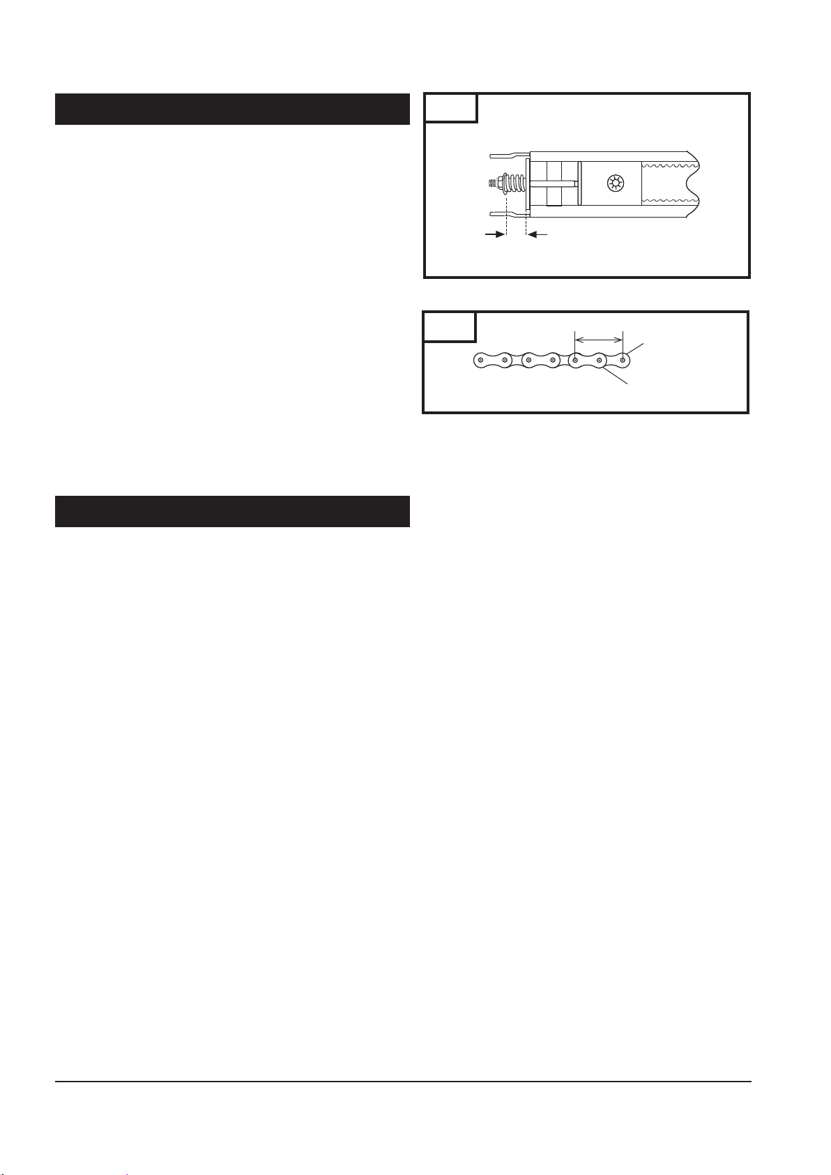
21. TENSION ADJUSTMENT
Your preassembled rail comes with the tension adjusted to factory
specifications. There should be no need for further adjustment.
However, if exposed or subjected to unusually harsh operating
conditions, the tension may need to be readjusted during the life
of the opener.
CHECK PROPER TENSION (Fig. 60):
Release trolley from belt or chain, then examine the setting of
the tension adjustment at the header end of the rail.
Proper tension is set when the tension nut is tightened just
enough so that the washer will be spaced approximately 21mm
or 53/64" from the stationary rail end-stop arch.
If the gap between the washer and the rail end-stop arch is too
big or too small, the tension needs to be adjusted.
ADJUST THE TENSION:
To increase the tension and tighten the belt or chain, turn the
tension nut clockwise with 7/16” wrench until the washer is
spaced properly from the rail end-stop arch. See Fig. 61.
Once the washer is spaced correctly, any additional tightening
will overtighten the belt or chain and may cause damage to the
system.
To loosen the tension, turn nut counterclockwise.
Reattach trolley.
Fig. 60
Proper Space 21mm + 0.5 or approximately (53/64”)
Fig. 61
Proper Tension Adjustment
1"
Chain Link
Chain Strap
22. RAIL LENGTH ADJUSTMENT
FOR PROFESSIONAL INSTALLERS ONLY
If your particular installation calls for a shorter rail than the
standard length provided, it is possible to shorten the rail.
NOTE: Shortening rail too much may result in door travel
length reduction and door not opening fully. This depends
on door size and configuration. Carefully plan all such
modifications before proceeding. THIS PROCEDURE SHOULD
BE PERFORMED ONLY BY A PROFESSIONAL INSTALLER FULLY
FAMILIAR WITH THIS TYPE OF OPENER SYSTEM.
TO SHORTEN BELT RAIL LENGTH:
Loosen belt tension as much as possible.
Remove screws from sprocket holder and rail end-stop.
Slide belt and all rail parts out of rail from header end. See rail
exploded view, Fig. 62 on p. 32, for disassembly details.
Measure and cut off excess rail from header end.
Using rail end-stop as a guide, mark and drill a 3/16" hole
for rail end-stop screw.
Disassemble connector to expose free ends of belt.
Using the same measurement as the excess rail length, cut the
same amount off BOTH free ends of the belt.
Reassemble belt connector, and slide all rail parts into rail from
header end according to original assembly (Fig. 60).
Tension belt properly (Fig. 60).
Check rail for proper assembly and operation by manually
moving trolley from end to end with trolley connected to belt.
TO SHORTEN CHAIN RIAL LENGTH:
Loosen chain tension as much as possible.
Remove screws from sprocket holder and rail end-stop.
Slide chain and all rail parts out of rail from header end.
See rail exploded view, Fig. 63 on p. 32, for disassembly
details.
Measure and cut off excess rail from header end by 1”
increment only.
Using rail end-stop as a guide, mark and drill a 3/16" hole
for rail end-stop screw.
Disassemble connector to expose free ends of chain.
Using the same measurement as the excess rail length,
remove the same amount off chain links and chain straps
from BOTH free ends of the chain (Fig. 61).
Reassemble two piece connector and slide chain and all
rail parts into rail from header end according to original
assembly (Fig. 60).
Tension chain properly (Fig. 60).
Check rail for proper assembly and operation by manually
moving trolley from end to end with trolley connected
to chain.
31
Page 34
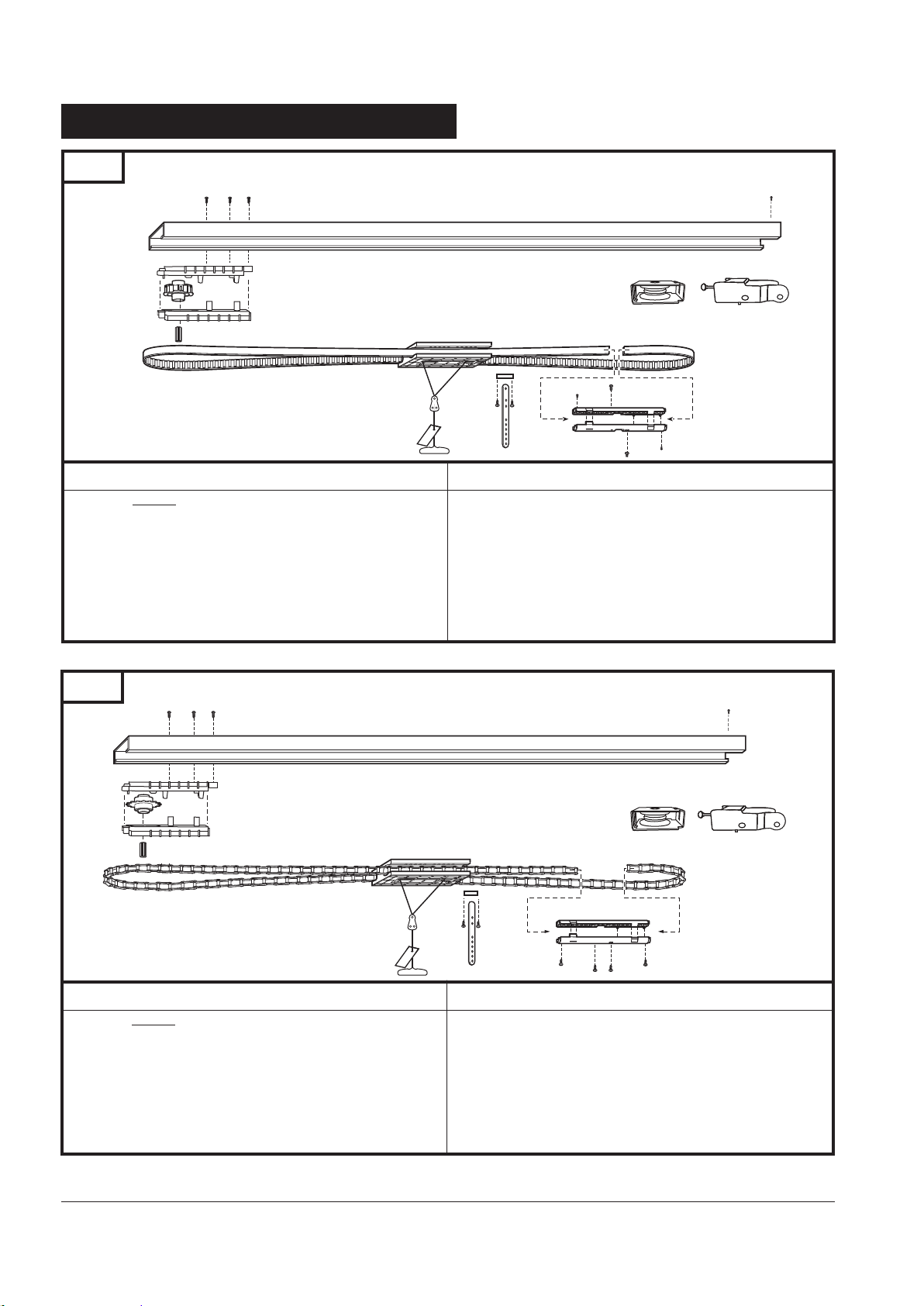
23. RAIL ASSEMBLY PARTS
Fig. 62
Model#: M13-807B (7' Door) M13-808B (8' Door) M13-810B (10' Door)
Operator End
1
2
Item Part # Description
1. Rail
2. 91567 Sprocket holder assembly
97484 Shaft adapter
3. 95358 Roller holder assembly
4. 91566 Rail end assembly
5. 8030196 Belt connector
Belt Rail Assembly
6
Item Part # Description
6. 115443 Trolley with connector (7’ Door)
115444 Trolley with connector (8’ Door)
115445 Trolley with connector (10’ Door)
7. 73636 Pin
8. 8030735 Straight door arm
Header End
3
7
5
8
4
Fig. 63
Model#: M13-807C (7' Door) M13-808C (8' Door) M13-810C (10' Door)
Operator End
1
2
Item Part # Description
1. Rail
2. 91568 Sprocket holder assembly
97484 Shaft adapter
3. 95358 Roller holder assembly
4. 91566 Rail end assembly
5. 8030234 Chain connector
Chain Rail Assembly
6
7
8
Item Part # Description
6. 115443 Trolley with connector (7’ Door)
115444 Trolley with connector (8’ Door)
115445 Trolley with connector (10’ Door)
7. 73636 Pin
8. 8030735 Straight door arm
Header End
3
5
4
32
Page 35
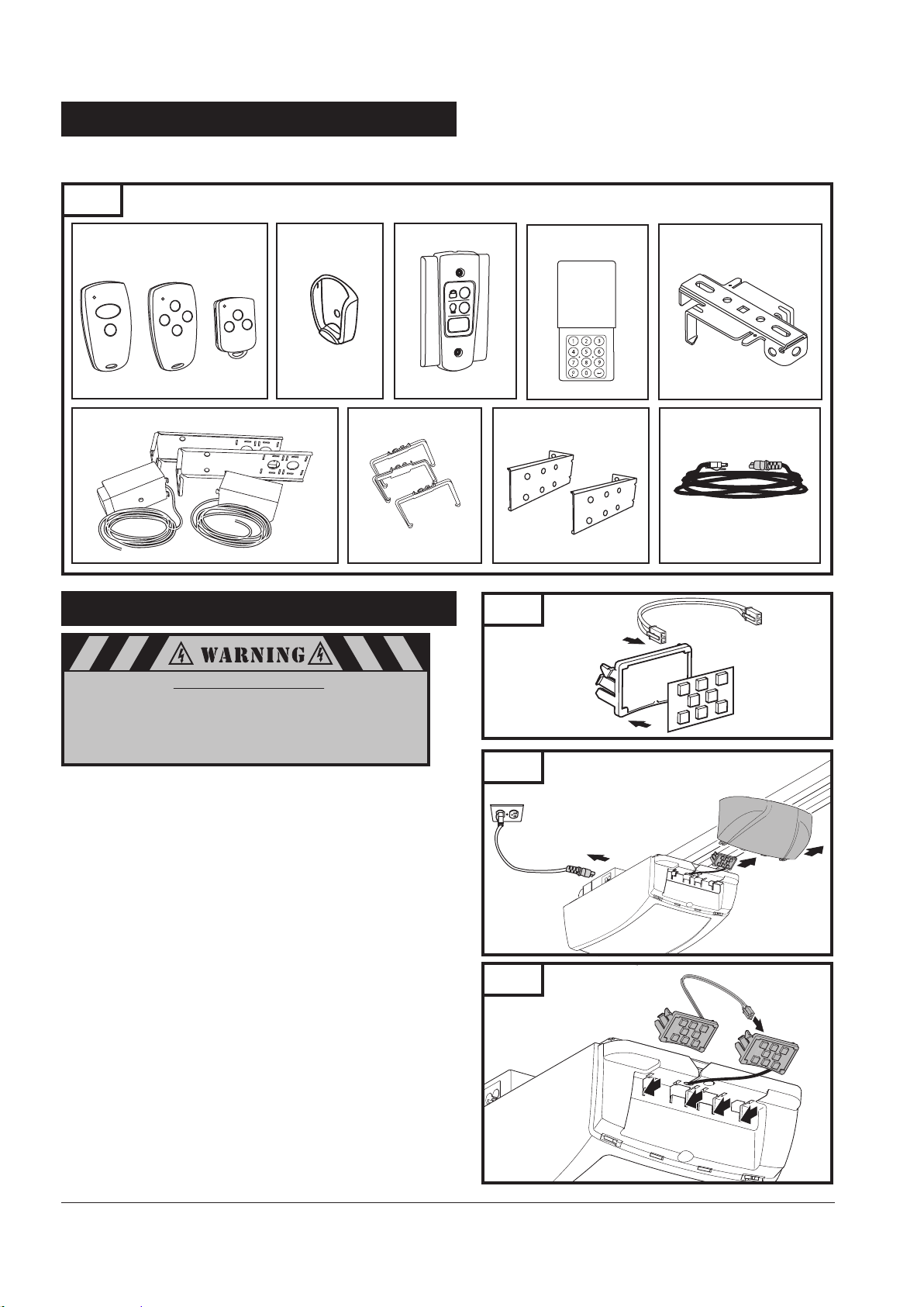
24. ACCESSORIES
Accessories are available from your dealer. If you have difficulty locating available accessories, please contact us directly
at 1-888-622-2489 or visit our website at www.marantecamerica.com.
Fig. 64
Mini & Micro Transmitters
(Battery and visor clip included)
M3-2312 M3-2314 M3-3313
Photo Eye Safety System
5“
M8-705
MINI Transmitter
Mounting Plate
6“
5.5”
5“
6“
5.5”
5“
6“
ML-920
Wall Control Panel
Wire Holder Kit
P/N: 86141
24-1. LED EL 200
Danger of electric shock:
Before any wiring work begin, make sure that the
operator and all wiring is disconnected from the power
supply. During wiring make sure all wires remain disconnected from the power supply at all times.
Assemble LED Cluster (Fig. 65):
Snap LED board into cluster holder.
Attach cable to LED board.
LED Cluster Installation:
Disconnect power cord from operator (Fig. 66).
Remove lens cover.
Disconnect LED cluster from operator’s housing.
Attach new cluster to existing cluster (Fig. 67).
Snap clusters in operator’s housing.
Replace lens cover.
Connect power cord to operator.
M3-543
Wireless Keyless
Entery System
M13-631
Extension Bracket Kit
P/N: 85678
Fig. 65
LED Cluster
P/N: 101160
Fig. 66
Fig. 67
Rail Support Bracket
P/N: 71865
Detachable Power Cord
P/N: 105475
33
Page 36
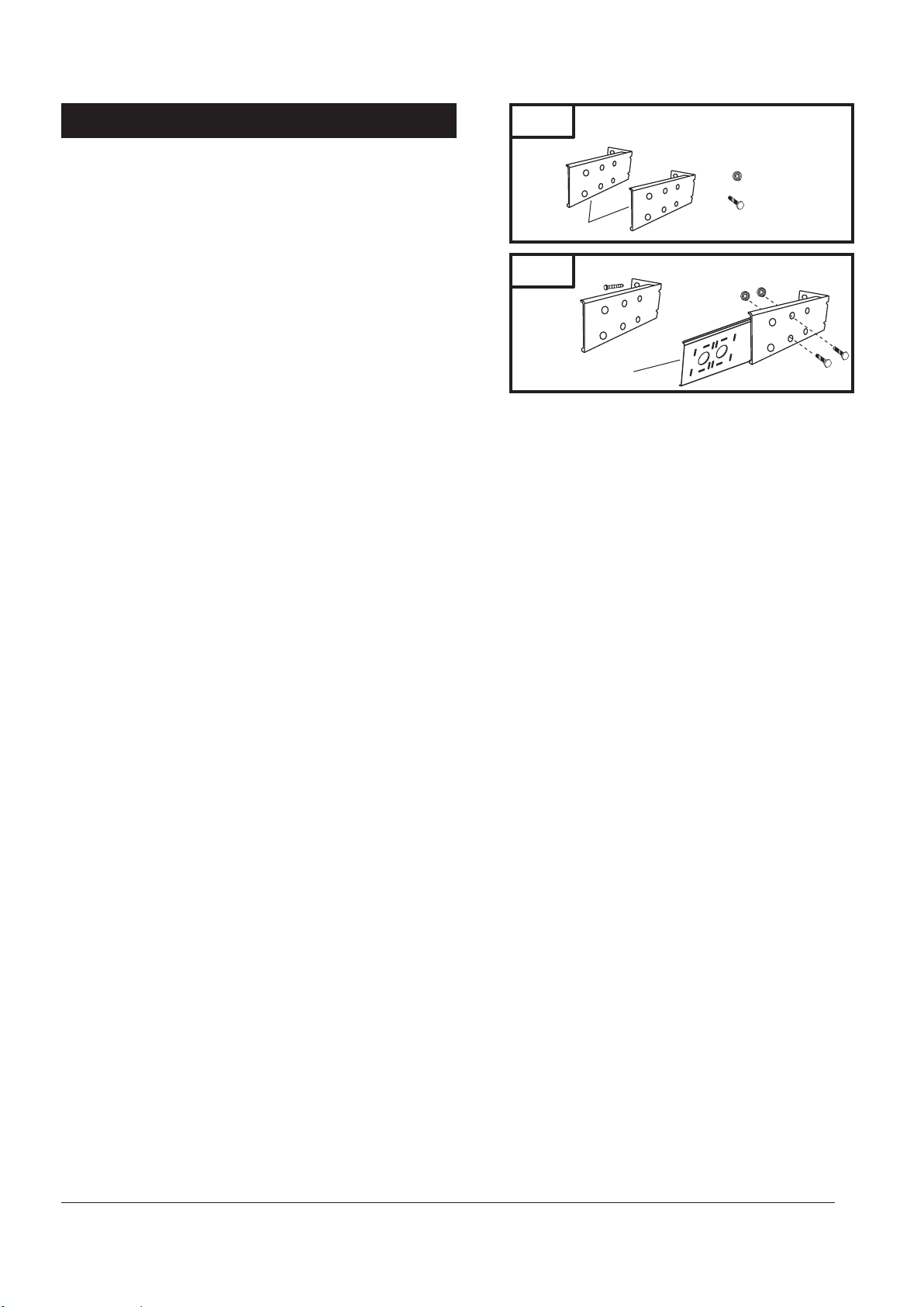
24-2. EXTENSION BRACKET KIT
Locate the mounting position for extension bracket as shown in Fig. 69.
Secure the bracket to the wall with two lag screws 1/4”x 1 1/2”
provided in operator’s hardware kit.
Attach photo eye bracket to extension bracket and secure with
hardware provided.
Repeat process for the other bracket.
Fig. 68
Extension Bracket
Extension Bracket Kit
P/N: 85678
1/4”-20 Flange nut (4)
1/4”-20 x 1/2”
Hex Head Bolt (4)
Fig. 69
Lag Screw
Photo eyes Bracket
1/4”-20 Flange nut
1/4”-20 x 1/2”
Hex Head Bolt
34
Page 37
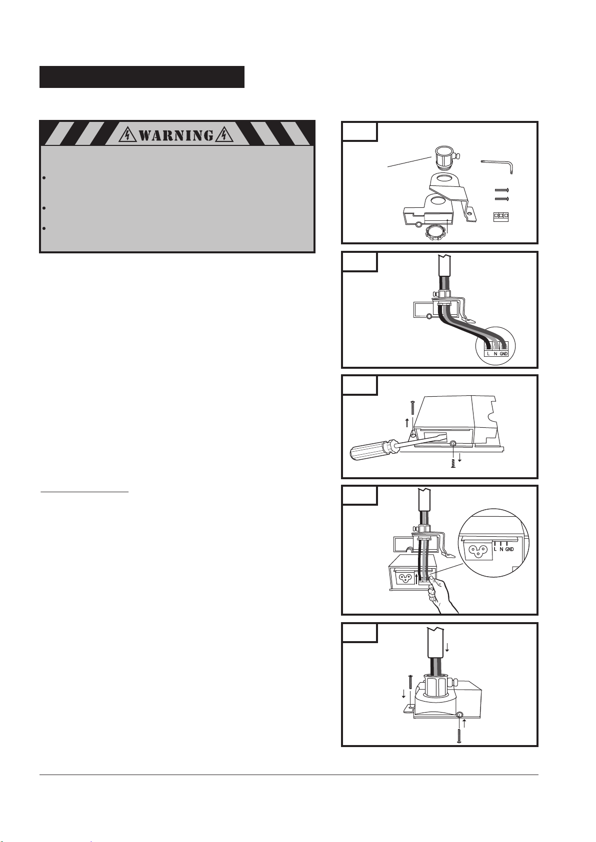
24-3. PERMANENT WIRING KIT
If permanent wiring is required by your local code refer to the procedure below.
To prevent possible SERIOUS INJURY or DEATH from electrocution
or fire:
Be sure power is not connected to the operator, and disconnect
power at circuit breaker BEFORE removing cover to establish
permanent wiring connection.
Garage door installation and wiring MUST be in compliance
with ALL local electrical and building codes.
NEVER use an extension cord, 2-wire adapter or change plug in
any way to make it fit outlet. Be sure the opener is grounded.
Become familiar with assembly parts shown in Fig. 70 for 1/2”
conduit permanent wiring installation..
Assemble conduit adapter, use parts as shown in Fig. 70.
Feed wires through conduit adapter assembly. Then connect
field wires to terminal block as shown in Fig. 71.
Remove screw from transformer module cover plate. Break cover
plate as shown in Fig. 72. Remove and save chassis screw.
Slide power board slightly out to make room to accept terminal
block on the power board pin connections as shown in Fig. 73*.
* Make sure the power board is seated on the
transformers module housing guides before sliding
it back in place.
Secure conduit adapter assembly to transformer module
enclosure, as shown in Fig. 74, with screw provided in kit.
Metal bracket secure to chassis with screw removed in step 2.
Run field wires through conduit.
Secure conduit to screw connector on assembly as shown in
Fig. 74.
Terminate and complete field wiring connection.
Fig. 70
1/2” set screw connector
(not provided)
Permanent Wiring Kit
Fig. 71
Fig. 72
P/N: 106223
TORX L-Key
Terminal Block
IMPORTANT NOTE:
Check installation then turn power “on” at breaker.
Fig. 73
Fig. 74
35
Page 38
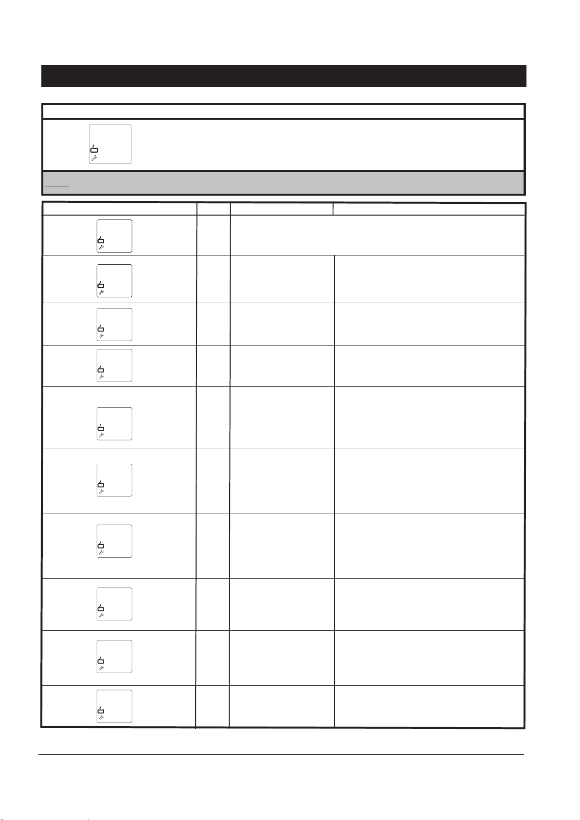
25. TROUBLESHOOTING
The operator displays the system fault(s) automatically one at a time as follows:
System Fault Display: (Example - Error Code 7)
Fault 1
7
Note: The last system fault code can be viewed by pressing the “P” button once. To return to operation mode press “-” or “+” button.
FAULT DISPLAY
7
8
9
10
11
15
16
CODE
7
8
9
10
11
15
16
PROBLEM
NOTICE:
Adjustments setting
interrupted before
completion.
Rational speed (RPM)
sensor impulse not
present, operator system
is obstructed.
The door does not move
easily or is obstructed.
Excess travel stop.
Photo eye sensors not
connected properly.
Photo eye sensors not
aligned.
Obstruction in the door
path (photo eye beam
broken).
The current sensor for the
monitoring motor
overload is defective.
If no buttons are pressed within 120 seconds, the programming mode
terminates automatically.
SOLUTION
Door can be operated normally. Recheck
adjustments if adjustment settings were not
completed. Refer to page 18.
Have operator serviced *
Have operator serviced *
The maximum driving power has been set too low.
Have maximum driving power checked by specialist *
Have operator serviced *
Check photo eye sensors wiring and connections.
Realign photo eye sensors.
Remove obstruction from door path.
Have operator serviced *
36
26
28
30
Power overload condition.
26
Door movement too
stiff or irregular.
Door blocked.
Operator operating
28
sensitivity set too
sensitive (low).
MS bus fault.
30
Have the outlet assigned for the operator and/or
supplied power checked.
Check door for obstructions, proper manual operation,
proper balance, or broken springs. Clear obstructions or
have door serviced, If needed.
Have the operating sensitivity settings checked by
an authorized dealer/installer.
Reset the bus modules.
Have the connected bus modules checked.
Page 39
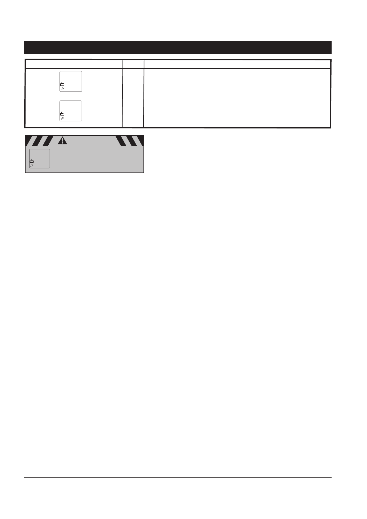
25. TROUBLESHOOTING (cont’d)
FAULT DISPLAY
CODE
35
PROBLEM
Electronic defect.
SOLUTION
Have operator serviced.
35
Wall control connected
incorrectly.
36
Check wall control terminals connection.
Reset operator.
36
caution
Short and rapid cycles are conducted with
the operator (motor). This condition could
result in overheating of motor / transformer.
33
* Contact Marantec Customer Service at our toll free number 1-888-622-2489 to find nearest authorized service center.
37
Page 40
26. MAINTENANCE AND ADJUSTMENTS
To ensure continued safe operation and extended life of your operator system, periodic checking for proper operation is necessary. Occasional
maintnance and readjustment of your system may also be needed.
MONTHLY:
Check reversal system by performing
“safety reversal test” described in this
manual.
Check proper operation of door by
manually moving door open and closed.
If door binds or sticks, or is out of balance
call for garage door service.
Check and test photo eye safety system
as described in this manual.
27. LIMITED PARTS WARRANTY
MARANTEC AMERICA CORPORATION
Synergy Professional Series Residential Garage Door Opener System
The Synergy 260 System Limited Warranty is 2 years for parts and a
Limited Lifetime* Warranty for the motor, gear assembly and rail system.
The Synergy 270 & 280 Systems Limited Warranty is 4 years for parts and a
Limited Lifetime* Warranty for the motor, gear assembly and rail system.
Marantec America Corporation warrants:
Battery Backup System (where applicable) and Accessories for 1 year.
ONCE EVERY
YEAR
Keep door rollers, hinges,
and bearings properly
lubricated by following
recommended door
instructions or contacting
a door service company
in your area.
Limited Parts Warranty
Synergy 260, 270, 280
LED Lighting System for 5 years
AS NEEDED:
Readjust operator travel limits and force settings as
necessary — due to cold weather, normal wear of door, etc.
For any periodic adjustments needed refer to this manual.
Check and readjust belt tension, if necessary, in the unlikely
event that it loses its proper tension during the life of the
operator. Always check the reversal system after any
adjustment of travel limits or forces. A door operator that is not
checked could possibly be out of adjustment and be dangerous.
THE LIMITED LIFETIME* PORTION OF THE WARRANTY IS FOR AS LONG AS THE ORIGINAL PURCHASER
OF THE MARANTEC SYSTEM OWNS HIS OR HER HOME OR 20,000 SYSTEM OPEN & CLOSE CYCLES,
WHICHEVER COMES FIRST.
Limited Warranty Coverage: THE LIMITED LIFETIME* WARRANTY IS FOR AS LONG AS THE
ORIGINAL PURCHASER OF THE MARANTEC SYSTEM OWNS HIS OR HER HOME, OR 20,000
SYSTEM OPEN & CLOSE CYCLES, WHICHEVER COMES FIRST. This Warranty applies, upon
purchase from a Marantec reseller and installation by a professional installer and registration of the
product within 14 days of the date of installation of the product, (or within 30 days of closing on a
new home from a developer) to any defect in materials or workmanship in the Marantec product
parts or components from personal, normal, household use in compliance with the Owner’s Manual
for a period of 2 years for the Synergy 260 and a period of 4 years for the 270 & 280 Systems from the
date of installation (or closing date) on its parts and, for the Limited Lifetime* portion of this
Warranty on the motor and rail system and belt, for as long as the original retail purchaser owns his
or her home or 20,000 system open & close cycles, whichever comes first. Marantec warrants this
Garage Door Opener system to its first retail, consumer purchaser only. This is not a commercial
product. Marantec disclaims any and all warranties in the event that the product is obtained from a
source which is not a Marantec authorized reseller or if the product is not installed by a professional
installer. “Grey market” purchases are not warranted or recognized in any manner whatsoever. This
is not a “do it yourself” product. There is no warranty if the seal on the Marantec carton is broken at
the time of sale, delivery or installation by a professional installer. No “aftermarket” installation,
alteration, opening of the housing or cases, modification or repairs are recognized or warranted.
Any of the foregoing conduct voids all warranty provisions. This warranty is for parts only and is not
for any service call(s) or labor in connection with the repair or replacement of the unit or its parts.
Parts will only be shipped to a Marantec authorized reseller.
38
Page 41

27. LIMITED PARTS WARRANTY (cont’d)
Marantec Accessories: Marantec accessories include such items as transmitters, wall controls, photo eye
systems, and wireless/keyless entry systems. These are warranted to be free from defects in materials or workmanship for 1 year from the date of installation or closing. At Marantec’s sole option, Marantec may elect to replace
the accessory with new or reconditioned parts, components or units utilizing product of the same or similar design
available at that given time. WITH RESPECT TO ACCESSORIES, ALL OTHER WARRANTIES, INCLUDING
FITNESS FOR PARTICULAR PURPOSE AND MERCHANTABILITY ARE SPECIFICALLY DISCLAIMED AND THE
LIMITED WARRANTY SET FORTH BELOW IN BOLD TYPE IS HEREIN INCORPORATED BY REFERENCE.
LED Lighting System and Battery Backup System: Marantec warrants the parts of the LED Lighting System,
including its lighting bar, LEDs, and lens covers for 5 years and the Battery Backup System (where applicable)
including its charging system and battery for 1 year from the date of installation or closing, if a new home
purchased from a developer. These are warranted to be free from defects in materials or workmanship for 1 year
from the date of installation or closing. At Marantec’s sole option, Marantec may elect to replace the System with
new or reconditioned parts, components or units utilizing product of the same or similar design available at that
given time. WITH RESPECT TO THE LED LIGHTING SYSTEM AND BATTERY BACKUP SYSTEM, ALL OTHER
WARRANTIES, INCLUDING FITNESS FOR PARTICULAR PURPOSE AND MERCHANTABILITY ARE
SPECIFICALLY DISCLAIMED AND THE LIMITED WARRANTY SET FORTH BELOW IN BOLD TYPE IS
HEREIN INCORPORATED BY REFERENCE.
Marantec does not warrant batteries (except the Battery Backup System battery above), sensors or LED bulbs
(except the LED Lighting System LEDs above). Unauthorized repairs or repair parts, installations, commercial use,
damage while in transit, defects or damage resulting from power washing, water or moisture exposure, or
accidents, power failure and surges, resulting from alterations, lack of proper maintenance, unauthorized repair
or modification of the product, opening of housing or case, misuse or abuse of the product, fire, flood, acts of
God, damage to doors, tracks, springs, hardware or the residence, its contents and vehicles, other property or
persons or other failures due to failure to follow the recommendations of the Owner’s Manual are not warranted.
This warranty applies only to Marantec systems purchased from authorized Marantec retail sellers and used in the
United States, its Territories or Canada. Marantec make no warranties outside the United States, its Territories or
Canada.
Marantec Commitment: If Marantec determines the product parts to be defective in materials or workmanship,
then Marantec will supply parts for the repair or replacement of the defect to the Marantec authorized professional installer at no cost to you. You must pay for the service call and labor for installation of the part(s)
determined to be defective by Marantec. At Marantec’s sole option, Marantec may elect to replace the part(s)
with new or reconditioned parts, components or units utilizing product of the same or similar design available at
that given time.
THIS LIMITED WARRANTY IS IN LIEU OF ANY OTHER WARRANTIES, EXPRESS OR IMPLIED, INCLUDING
ANY IMPLIED WARRANTIES OF MERCHANTABILITY OR FITNESS FOR A PARTICULAR PURPOSE, OR
OTHER WARRANTIES IMPLIED BY STATUTE, AND OF ANY OTHER OBLIGATIONS OR LIABILITY ON THE
PART OF MARANTEC AMERICA CORPORATION. THIS LIMITED WARRANTY DOES NOT COVER
NON-DEFECT DAMAGE CAUSED BY IMPROPER INSTALLATION, OPERATION OR CARE AND MAINTENANCE, INCLUDING BUT NOT LIMITED TO ABUSE, MISUSE, POWER SURGE, FAILURE TO PROVIDE
REASONABLE AND NECESSARY MAINTENANCE OR ANY ALTERATIONS TO THIS PRODUCT. LABOR
CHARGES FOR DISMANTLING OR REINSTALLING A REPAIRED OR REPLACED UNIT ARE EXCLUDED.
UNDER NO CIRCUMSTANCES SHALL MARANTEC AMERICA CORPORATION BE LIABLE FOR CONSEQUENTIAL, INCIDENTAL OR SPECIAL DAMAGES ARISING IN CONNECTION WITH THE USE OR INABILITY TO USE
THIS PRODUCT OR THE PREMISES IN WHICH IT IS UTILIZED. IN NO EVENT SHALL MARANTEC AMERICA
CORPORATION INCUR LIABILITY FOR BREACH OF WARRANTY, BREACH OF CONTRACT, NEGLIGENCE OR
STRICT LIABILITY IN EXCESS OF THE COST OF THE PRODUCT COVERED HEREBY. NO PERSON IS
AUTHORIZED TO ASSUME, FOR MARANTEC AMERICA CORPORATION, ANY OTHER LIABILITY OR MAKE
ANY MODIFICATIONS OR EXTENSIONS TO THE WARRANTY OF THIS PRODUCT. THIS LIMITED
WARRANTY MAY NOT BE TRANSFERRED OR ASSIGNED.
39
Page 42

28. WARRANTY LIMITATIONS, CLAIMS AND SERVICE:
This Limited Warranty is the one which Marantec gives on this product and sets forth all of its responsibilities
regarding the Marantec product. There are no other express or implied warranties. Installation by unauthorized
personnel or use of unauthorized parts or accessories could cause improper operation and even create dangerous
conditions and voids all warranties. This could void the UL Safety Approval of the product and constitute a safety
hazard.
This Limited Warranty contains the entire warranty on the product. All discussions, representations or negotiations
between the consumer and the retail seller are merged into this Limited Warranty, and there are no understandings or warranties other than those herein. None of the terms of the Limited Warranty shall be waived or modified
to any extent, except by a written instrument signed and delivered by Marantec’s Corporate Officer.
This Limited Warranty is being delivered in Gurnee, Illinois, USA and is intended to be performed in the State of
Illinois and shall be construed and enforced in accord with the laws and statutes of the State of Illinois without
regard to or application of its rules on the conflict of laws, with the proper venue for any disputes being that of
Marantec’s registered office in Illinois or its corporate offices in Gurnee, Illinois, whichever Marantec elects.
Marantec expressly disclaims the application to this Limited Warranty of the 1980 United Nations Convention on
the International Sale of Goods. Any interpretation of this Limited Warranty shall be conducted in English and no
other language. ALL CLAIMS AND CAUSES OF ACTION OF ANY NATURE AGAINST MARANTEC AMERICA
CORPORATION SHALL BE BROUGHT WITHIN 1 YEAR OF THE DATE OF DISCOVERY OF THE CLAIM.
In the event any action or proceeding or claim is asserted or brought against Marantec, if Marantec prevails, then
Marantec shall be entitled to recover all costs and expenses, including the actual fees of its attorneys and expert
or professional witnesses incurred in connection with such action or proceeding or claim.
This Limited Warranty becomes valid only upon the receipt of "Payment in Full" by Marantec from the Marantec
reseller and upon receipt of “Payment in Full” by the Marantec reseller from the end user. This Limited Warranty
is null and void if the System is not installed within 24 months of the date of manufacture as marked on the product housing. This Limited Warranty is void outside the United States, its Territories and Canada.
Whenever possible, each provision of this Limited Warranty shall be interpreted in such a manner as to be effective
and valid under applicable Illinois law. If any provisions of this Limited Warranty are prohibited or invalidated
under applicable law, then such provisions shall only be ineffective to the extent of such prohibition or invalidity,
without invalidating the remaining provisions of this Limited Warranty.
Some jurisdictions do not allow the exclusion or limitation of consequential, incidental or special damages, so the
above limitations or exclusions may not apply to you. This Limited Warranty gives you specific legal rights and you
may also have other rights which vary from state to state.
29. REGISTRATION
This Warranty becomes effective upon registration at the Marantec web site: www.marantec.com. If you do not have
access to the internet, please fill out and send in enclose warranty card.
30. FOR WARRANTY SERVICE
Contact your professional installer for all service. Service by anyone other than a professional installer voids this
warranty. If you cannot locate your installer, please telephone the Marantec Customer Service Representative
at 888-622-2489.
40
Version: 6/15 Part #119468
 Loading...