

Marani DPA-260A User Manual
19"
482mm
DIGITAL
USB

1
36
DPA-260A Speaker Management
DPA-260A Connection.............................................Page37
2
Note: in order to ensure safety, please read these instructions carefully.
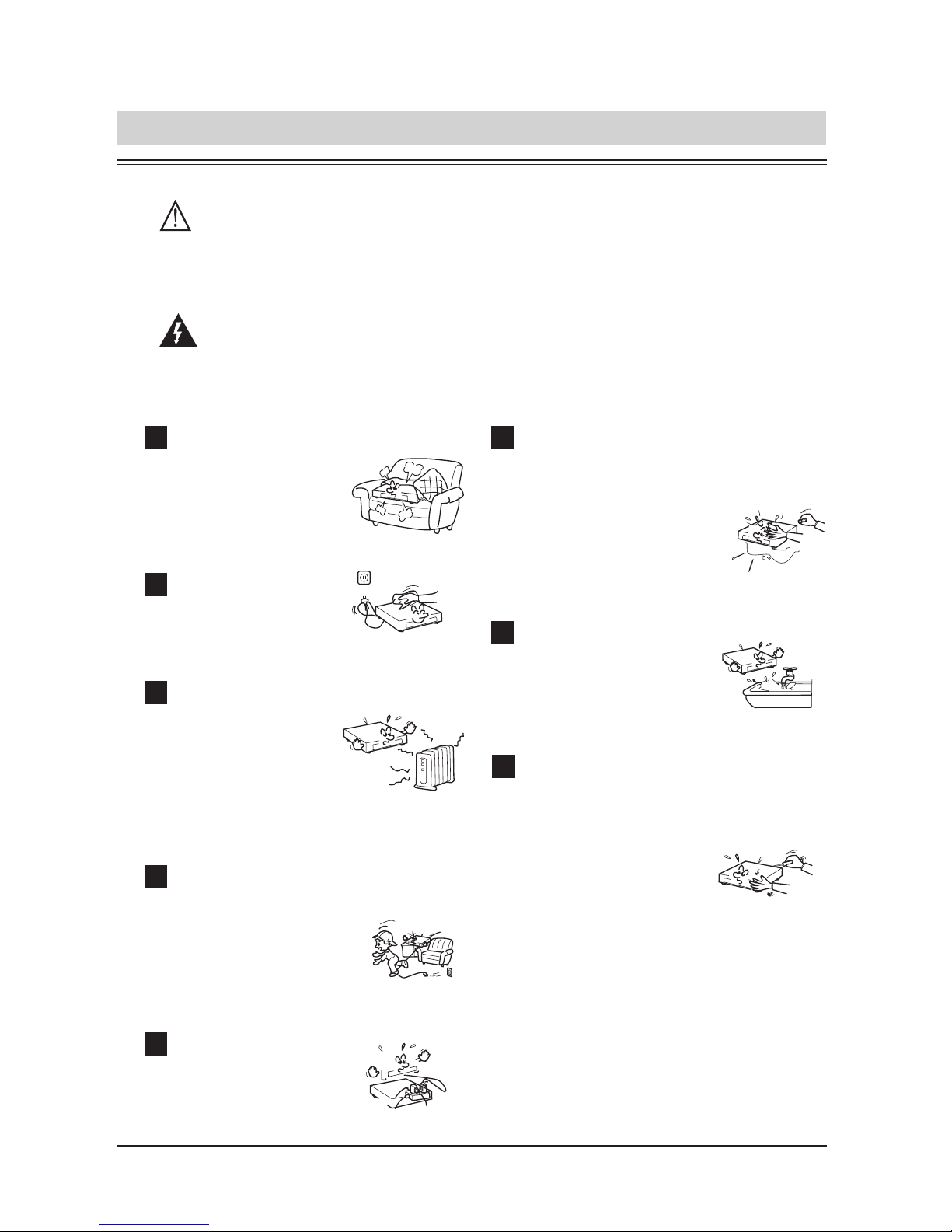
IMPORTANT SAFETY INSTRUCTIONS
Attention:To reduce the risk of fire or electric shock, do not expose
this apparatus to rain or moisture!
Ventilation
1
Overload
5
Heat sources
3
Power cord proctecion
4
2
Maintenance
8
7
Humidity
Cleaning
Do not install near
any heat sources
such as radiators,
stoves, or other
apparatus that
Power plug should
not overload.
Be careful that no objects
fall or liquid is spilled
inside the unit through
ventilation openings.
The unit should far
away form water.
Refer all servicing to
qualified service
personnel. To prevent
the risk of shock, do
not attempt to service
this equipment
yourself because
opening or removing
covers may expose
you to
dangerous voltage or
other hazards.
Do not block
any ventilation
openings.
Clean only with dry
cloth.
Protect the power cord
from being walked on
or pinched particularly
at plugs.
All safety and operating instructions should be read before the
product is operated.
6
Objects or liquid entry
inside the unit
3
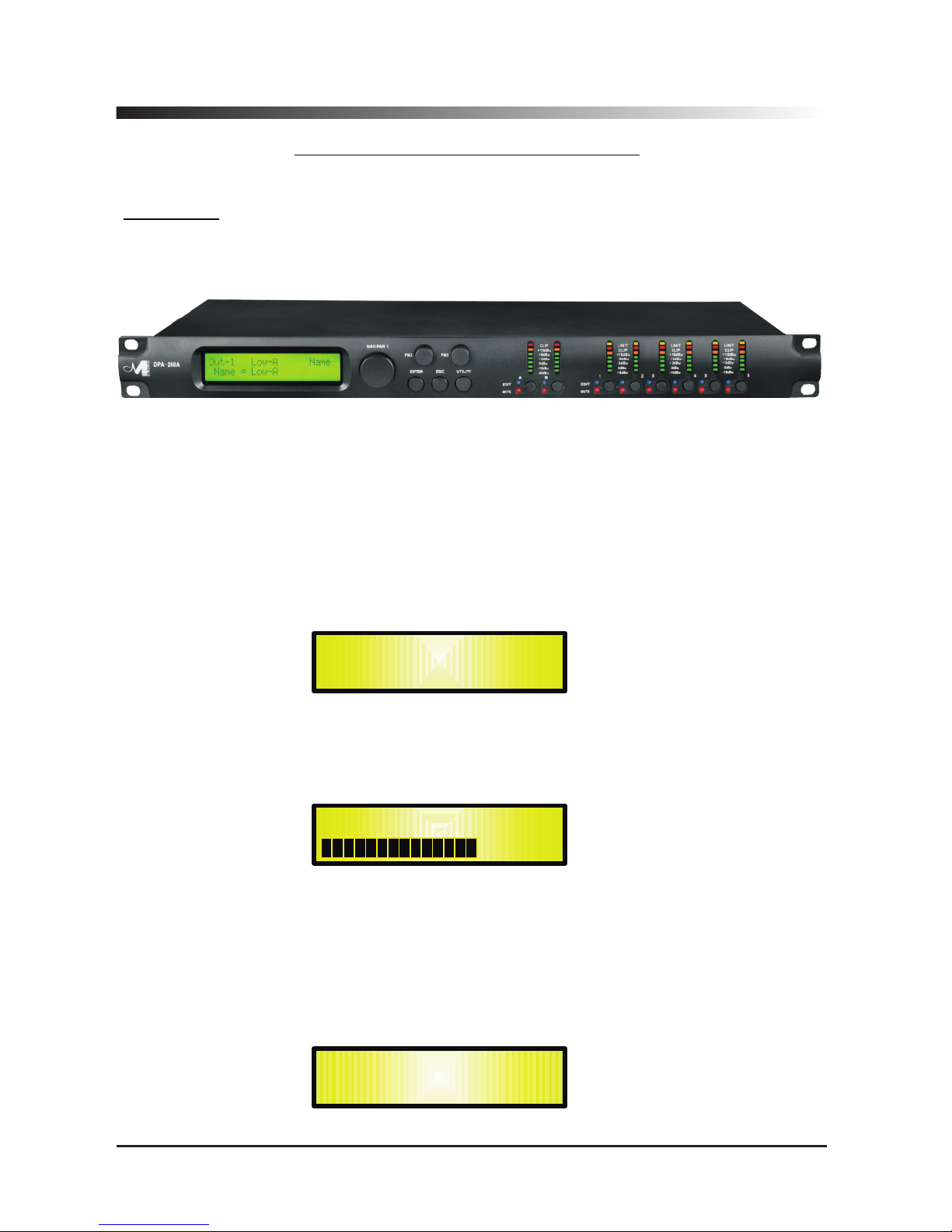
DPA-260A Digital Speaker Processor
User Manual
Described below are the functions of the front panel control buttons and encoders for
the DPA-260A.
• Getting Started
As soon as the DPA-260A is turned ON the device model name will appear in the LCD screen:
and a status bar will show the progress of the DPA-260A initialization process:
The DPA-260A has three factory pre-set working modes: “2x2 Ways Xover + Sub”, “2x3
Ways Xover” and “6 Ways Xover”.
After the initialization, the DPA-260A will show on the LCD the first of the embedded preset
working modes, or the last one selected prior to the unit being turned off.
First time activation will default to the first of the preset working modes.
DPA260-A
Speaker Management
DPA260-A
2x3 WAY X-OVER
DP260- A

• Encoders and ENTER, ESC buttons
The DPA-260A is equipped with 3 Relative Encoders, “NAV/PAR1”, “PM2” and “PM3”, These
encoders allow you to navigate the user interface and edit sections of the processor. They allow
the user to navigate within the screen for the selection of sub-menus, pages and parameters and
to select the values to be assigned during the editing operations.
The “ENTER” and “ESC” buttons allow the user to confirm or NOT confirm the operations
performed by the encoders.
• UTILITY, A/B and 1/2/3/4/5/6 buttons
The UTILITY button allows the User to enter the Sub-menus and set the general characteristics of
the Processor. The A and B buttons allow the User to enter the Editing Menus of the Processor's
Input Channels and buttons 1, 2, 3, 4, 5 and 6, allow the User to enter the Editing Menus of the
Processor's Output Channels.
The A and B buttons as well as the 1, 2, 3, 4, 5 and 6 buttons have double functions dependent
on the push and hold time.
When the A and B buttons are pushed and held for more than one second Input Channels A or B
are either muted or unmuted. The red LED will illuminate when the Channel is muted. When the
“MUTE” LED is OFF, then the related Input Channel is UN-MUTED.
A momentary push of the A and B buttons enters the Editing Mode for the Input Channels (see
later for the Input Channel Editing details).
The blue “EDIT” LED will now be ON.
When the 1, 2, 3, 4 , 5 and 6 buttons are pushed and held for more than one second the Output
Channels 1, 2, 3, 4 , 5 and 6 are either muted or unmuted. The red LED will illuminate when the
Channel is muted. When the “MUTE” LED is OFF, then the related Output Channel is UN-MUTED.
A momentary push of the 1, 2, 3, 4 , 5 and 6 buttons enters the Editing Menu for the Output
Channels (see later for the Output Channel Editing details). The blue “EDIT” LED will now be ON.
• DPA-260A Menu and Sub-Menu Structures
As stated above, the start-up default screen is the following factory preset:
From this point, sub-menus are accessed using the UTILITY”,“A/B”, “1/2/3/4/5/6”, “ENTER” and
“ESC” buttons and all parameters and values are navigated by the “NAV/PAR1”,“PM2”and“PM3”
encoders. Please refer to the following menu structures:
DPA260- A
2x3 WAY X-OVER
4

MENU “UTILITY MENU” [Access by pushing the “UTILITY” button]
NAV/PAR1 Encoder PM2 or PM3 Encoder
[to navigate between menus] [to chose option, then ENTER to load it;
(*) indicates the selected option]
1 UTILITY MENU:......
<< System Utilities >>
1.1 SYSTEM UTILITY: System Setup
<< System Setup >> Setup: 2x2 WA+ SUB *
Setup: 2x3 WAY XOVER
Setup: 6 WAY XOVER
1.2 SYSTEM UTILITY: Input Routing
<< Input Routing >> Source: Analog *
Source: Digital
1.3 SYSTEM UTILITY: Power-On Procedure
<< Power-On Procedure >> Fade-In: On *
Fade-In: Off
1.4 SYSTEM UTILITY: Delay Units
<< Delay Units >> Unit: Time(ms) *
Unit: Distance (m)
1.5 SYSTEM UTILITY: Ramps on changes
<< Ramps on changes >> Ramps: Off *
Ramps: On
1.6 SYSTEM UTILITY: Software Version
<< Software Version >> Version: V1.01 *
2 UTILITY MENU:......
<< Program Utilities >>
2.1 PROGRAM UTILITY: Recall a Program
<< Recall a Program >> 01: Preset 01
: :
24: Preset 24
2.2 PROGRAM UTILITY: Save a Program
<< Save a Program >> 01: Preset 01
: :
24: Preset 24
2.3 PROGRAM UTILITY: Delete a Program
<< Delete a Program >> 01: Preset 01
: :
24: Preset 24
3 UTILITY MENU:......
<< Interface Utilities >>
3.1 INTERFACE UTILITY: Interface Setup
Interface Setup Source: USB
Source: RS485 *
4 UTILITY MENU:......
<< Security Utilities >>
4.1 SECURITY UTILITY: Parameter will
Show Parameter be shown *
not be shown
4.2 SECURITY UTILITY: Lock Unit
Lock Unit Lock: Off *
Lock: On
4.3 SECURITY UTILITY: User Password
User Password [ ]
4.4 SECURITY UTILITY: Enable Password (For the details about the Password Setting/Enable
Enable Password Password: Enable and Unit Lock, , refer to the “Utility Menus Use”
Password: Disable * Section)
ENTER
ESC
ENTER
ESC
ENTER
ESC
ENTER
ESC
ENTER
ESC
ENTER
ESC
ENTER
ESC
ENTER
ESC
ENTER
ESC
ENTER
ESC
ENTER
ESC
ENTER
ESC
ENTER
ESC
ENTER
ESC
ENTER
ESC
ENTER
ESC
ENTER
ESC
ENTER
ESC
ENTER
ESC
5

MENU “Input A/B” Input Channels Editing [Access by pushing the “A/B” buttons]
NAV/PAR1 Encoder NAV/PAR1 Enc . PM2 Enc. PM3 Enc.
[to navigate between menus] [to chose values for the parameters, no need to confirm the chosen values,
which are automatically loaded during the encoders use]
1. Input A/B Gain
Gain = + 0.0 dB
-> Gain = + 0.0 dB PAR1 N/A -12 db Same as PAR2
:
+6 dB
2. Input A/B Delay
Delay = 0.000 ms
-> Delay = 0.000 ms PAR1 N/A 000.0000mS 000.0000mS
[1 ms steps] [20.8 us steps]
848.0000mS 000.9984mS
3. Input A/B PEQ/SHV - 1/5
1.00kHz BW/SHV_Slope=1.00/up to -12dB + 0.0dB (when the filter's gain = 0.0dB ONLY, through the PM2 it is possible to
chose and select between a Bell or a Shelving filter)
If through the PM2, being the filter's gain = 0.0dB,
has been selected a Bell filter , just defining its Bandwidth
BW to be greater then 0, then the Bell filters can be set by
the following parameters
3.1 Input A/B EQ-X (up to 5 filters available)
-> 1.00kHz BW=1.00 +0.0dB [Freq.] 20Hz [BW] 0.05
[Amp.] -15.0 dB
: : :
20kHz 3.00 +15.0 dB
If through the PM2, being the filter's gain = 0.0dB,
has been selected a Low Shelving filter , just defining its
Slope (1st or 2nd order available, -6dB or -12dB), then the
Low Shelving filter can be set by the following parameters
3.2 Input A/B EQ-X (up to 5 filters available)
-> 1.00kHz (-6/-12)LoSh +0.0dB [Freq.] 20Hz PM2 N/A
[Amp.] -15.0 dB
: :
20kHz +15.0 dB
If through the PM2, being the filter's gain = 0.0dB,
has been selected a High Shelving filter , just defining its
Slope (1st or 2nd order available, -6dB or -12dB), then the
High Shelving filter can be set by the following parameters
3.3 Input A/B EQ-X (up to 5 filters available)
-> 1.00kHz (-6/-12)HiSh +0.0dB [Freq.] 20Hz PM2 N/A [Amp.] -15.0 dB
: :
20kHz +15.0 dB
ENTER
ESC
ENTER
ESC
ENTER
ESC
6

MENU “1/2/3/4/5/6 Output Channels Editing” [Access by pushing the “1/2/3/4/5/6” buttons]
NAV/PAR1 Encoder NAV/PAR1 Enc . PM2 Enc. PM3 Enc.
[to navigate between menus] [to chose values for the parameters, no need to confirm the chosen values,
which are automatically loaded during the encoders use]
1. Output [x] [Name] HPF
20.0 Hz No Cut-Off
-> 20.0 Hz No Cut-Off PAR1 N/A [Freq.] 20Hz [Type/Slope] No Cut-Off
: :
20kHz Bessel 24dB/Oct
2. Output [x] [Name] LPF
20.0 Hz No Cut-Off
-> 20.0 Hz No Cut-Off PAR1 N/A [Freq.] 20Hz [Type/Slope] No Cut-Off
: :
20kHz Bessel 24dB/Oct
3. Output [x] [Name] PEQ/SHV - 1/7
1.00kHz BW/SHV_Slope=1.00/up to -12dB + 0.0dB (when the filter's gain = 0.0dB ONLY, through the PM2 it is possible to
chose and select between a Bell or a Shelving filter)
If through the PM2, being the filter's gain = 0.0dB,
has been selected a Bell filter , just defining its Bandwidth
BW to be greater then 0, then the Bell filters can be set by
the following parameters
3.1 Output[x] [Name] EQ-X (up to 7 filters available)
-> 1.00kHz BW=1.00 +0.0dB [Freq.] 20Hz [BW] 0.05
[Amp.] -15.0 dB
: : :
20kHz 3.00 +15.0 dB
If through the PM2, being the filter's gain = 0.0dB,
has been selected a Low Shelving filter , just defining its
Slope (1st or 2nd order available, -6dB or -12dB), then the
Low Shelving filter can be set by the following parameters
3.2 Output[x] [Name] EQ-X (up to 7 filters available)
-> 1.00kHz (-6/-12)LoSh +0.0dB [Freq.] 20Hz PM2 N/A
[Amp.] -15.0 dB
: :
20kHz +15.0 dB
If through the PM2, being the filter's gain = 0.0dB,
has been selected a High Shelving filter , just defining its
Slope (1st or 2nd order available, -6dB or -12dB), then the
High Shelving filter can be set by the following parameters
3.3 Output[x] [Name] EQ-X (up to 7 filters available)
-> 1.00kHz (-6/-12)HiSh +0.0dB [Freq.] 20Hz PM2 N/A
[Amp.] -15.0 dB
: :
20kHz +15.0 dB
4. Output [x] [Name] Vu-Meter
Vu-Meter = Level
-> Vu-Meter = Level PAR1 N/A Level Same as PAR2
Limiter Act.
5. Output [x] [Name] Name
Name = [Name]
-> Name = _ (For Editing the Device's Name, refer to the Details on the“Utility Menus Use” Section)
ENTER
ESC
ENTER
ESC
ENTER
ESC
ENTER
ESC
ENTER
ESC
7

6. Output[x] [Name] Source
Source = InA
-> Source = InA PAR1 N/A. InA (Channel A) Same as PAR2
InB (Channel B)
InA+InB (Channel A+ Channel B)
7. Output[x] [Name] Gain
Gain = + 0.0 dB
-> Gain = + 0.0 dB PAR1 N/A -12 db Same as PAR2
:
+6 dB
8. Output[x] [Name] Limiter
A: 5ms R: 0.2s +20dB
-> A: 5ms R: 0.2s +20dB [Atk time] 5ms [Rel time] 0.1s
[Amp.] -10.0 dB
: : :
200ms 3.0s +20.0dB (OFF)
9. Output[x] [Name] Delay
Delay = 0.000 ms
-> Delay = 0.000 ms PAR1 N/A 000.0000mS 000.0000mS
[1 ms steps] [20.8 us steps]
848.0000mS 000.9984mS
10. Output [x] [Name] Polarity
Polarity = Normal
-> Polarity = Normal PAR1 N/A Normal Same as PAR2
Invert
ENTER
ESC
ENTER
ESC
ENTER
ESC
ENTER
ESC
ENTER
ESC
8

● Menu “UTILITY” [access by pushing the “UTILITY” button]
From the “Default Screen”, it is possible access the“UTILITY”menu pushing the“UTILITY”button
and the Sub-Menus pages can be selected just rotating clockwise and counter-clockwise the
“NAV/PAR1” encoder.
Once selected the sub-menu page, using the “ENTER” button can be accessed the Sub-Menus
pages, again “scrollable” using the “NAV/PAR1” encoder and accessible for the parameters' editing
pushing again the “ENTER' button.
Through the “ESC” button, it is any time possible to go back to the action and page preceding the
“ENTER” button use.
Once inside the Sub-Menus pages, the several options can be scrolled and using the PM2 or PM3
encoders and selected/confirmed pushing the “ENTER” button.
Note: In every Sub-Menu the option currently selected/running will have an asterisk “ *
” showing
to the right of the description on the LCD screen.
Options that are not selected/running will be displayed with NO Asterisk.
Pushing the ENTER button on an unselected option will mean an asterisk will then appear and this
option will now take over as the currently selected/running option.
System Utilities Sub-menu
– this sub-menu allows to access several operations related to the
DPA-260A Start Up and General Configuration:
From the “System Utilities Sub-menu”, pushing “ENTER”and then using the“NAV/PAR1”encoder
for scrolling will give access to the following pages:
– System Setup: this page allows the selection of the operating mode of the DPA-260A:
The operating mode can be chosen from a selection of 3 Xovers options:
2x2 WAY + SUB ...........
in this operating mode, the DPA-260A is performing a 2 Input to 4
Outputs X-Over, plus a SUB configuration, where the 2 Inputs are automatically assigned to
the Outputs as follows:
– Input A to Outputs 1/3 [Out1=Low-A and Out3=High-A]
– Input B to Outputs 2/4 [Out2=Low-B and Out4=High-B]
– Input A + Input B to Outputs 5/6 [Out5=Sub-A and Out6=Sub-B]
2x3 WAY ..XOVER.........
in this operating mode, the DPA-260A is performing a 2 Input to 6
Outputs X-Over, where the 2 Inputs are automatically assigned to the Outputs as follows:
– Input A to Outputs 1/3/5 [Out1=Low-A , Out3=Mid-A and Out5=High-A]
– Input B to Outputs 2/4/6 [Out2=Low-B , Out4=Mid-B and Out6=High-B]
SYSTEM UTILITY
– System Setup --
UTILITY MENU
– System Utilities --
9

6 WAY ..XOVER.......
in this operating mode, the DPA-260A is performing a Mono Input to 6
Outputs X-Over, where the Input A is automatically assigned to the Outputs as follow:
–
Input A to Outputs 1/2/3/4/5/6 [Out1=Near-1, Out2=Near-2, Out3=Mid-1 and
Out4=Mid-2, Out5=Far-1, Out6=Far-2]
By pressing ENTER on the System Setup page and rotating the“PM2”or“PM3”encoder, it
is possible to select all the available X-Over preset modes.
When the “2x3 WAY XOVER” is selected, the “System Setup” page will appear as follows
:
To change the desired operating mode for the DPA-260A, the screen must reflect the xover
required and then simply pressing the “ENTER” button will bring up the following screen asking
for confirmation to load the selected operating mode:
If confirmed by pressing ENTER the selected preset mode will load. While the device is
configuring the Xover the following screen will be appear:
The new preset mode will now be shown with an asterisk.
New Xover
[ENTER] to confirm
Please Wait .....
Changing Xover
System Setup
Setup: 2x3 WAY XOVER *
10

– Input Routing:
the DPA-260A Processor is equipped with 2 Analog Inputs (Balanced Female
XLR) and a stereo S/PDIF Digital Input (RCA connector).
The “Routing Options” page allows you to select the desired Input type:
By pressing ENTER on Input Routing and then rotating the “PM2” or “PM3” encoders, it is
possible to select the Main Inputs for the DPA-260A, allowing the User to choose between
Analog or S/PDIF Digital.
The selection can be confirmed by pressing the “ENTER” button.
The following screen shows that the Analog Input has been selected:
– Power-On Procedure:
this gives you the ability to select the option that will apply when the
DPA-260A powers up after being switched on:
By pressing ENTER and rotating the“PM2”or “PM3”encoder, it is possible to choose between
two options: Fade In On” or “Fade In Off”.“
The currently running option will be displayed with an asterisk to the right of the option
description.
To change the option simply ENTER on the option not displaying the Asterisk and that option
will become active and an Asterisk will now appear to the right of the option description.
The following two options are available:
FADE-In = Off...
when the DPA-260A is turned on all Outputs regard of their status before
the Unit was switched off, will be MUTED or UNMUTED automatically, meaning the DPA-260A
will have no active Outputs or active Outputs, during the start-up process.depending from the
FADE-In = On...
when the DPA-260A is turned on all Outputs not previously muted before
the Unit was switched off will be active, meaning the DPA-260A outputs will be controlled by a
volume ramp to avoid any sudden sound.
If the option “Fade-In=On” is selected, the screen will show the following:
Power-On Procedure
Fade-In: On *
Input Routing
Source: Analog *
SYSTEM UTILITY
– Input Routing --
SYSTEM UTILITY
– Power-On Procedure --
Outputs’ previous status.
11
 Loading...