

Marani DPA240P User Manual
2 In - 4 Out Speaker Management System
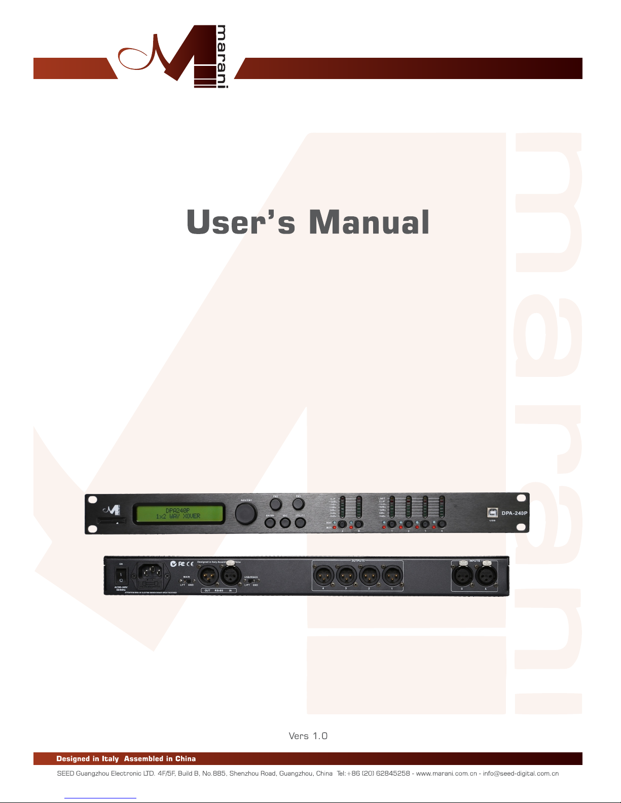
DPA240P
2 In - 4 Out Speaker Management System
2 In - 4 Out Speaker Management System
DPA24 0P i s a cos t-e ffe cti ve 2 -IN /4- OUT dig ita l spe aker m ana gem ent syst em. Designed t o be c ate red for any
cr oss ove r con fig ura tio n, it p rov ide s t he su ita ble p roc ess ing a nd co ntr ol fo r live a ppl ica tio n use . It of fer s 2 a nal og
in put s,a nd 4 an alo g out puts, man age d by a po wer ful D SP En gin e, in ad dit ion t o 24 Bi t AD/ DA Co nve rte rs. E ach
in put cha nne l pr ovi des a ch oic e of EQ wit h a 5-ba nd Par ametric EQ, gain con tro l, nois e ga te func tio n an d
co nfi gur abl e del ay. E ach o utp ut of fer s up to 5 -ba nd of p ara met ric e qua liz ati on in t o the c ros sov er fi lte rs which
th ems elv es p rov ide sl ope s fr om 6 dB/ Oct ave up to 4 8dB /Oc tav e. E ach ou tpu t pa th a lso fea tur es pea k li mit er a nd
dr ive r a lig nme nt del ay. The DPA24 0P sup por ts a fu ll mat rix mi xin g m ode wh ere in put s may b e r out ed/ mixed in any
ra tio to a ny out put . For rem ote conf igu rat ion and con tro l the D PA2 40P can be c onn ect ed via USB or R s48 5
co nne cti ons . T he con trol rem ote PC so ftw are allows sim ult ane ous co ntr ol up to 32 un its , s ett ing al l par ame ter s
an d sho win g rea l tim e lev els .
CAUTION
RI SK O F ELE CT RI C SHO CK
DO N OT O PEN
WAR NING
TO R EDU CE T HE RI SK OF F IRE O R EL ECT RIC
SH OCK D O NO T EXP OSE T HIS E QU IPM ENT T O
RA IN OR M OI STU RE
In tro duct ion
Described below are the functions of the front panel control buttons and encoders for
the DPA240P.
• Getting Started
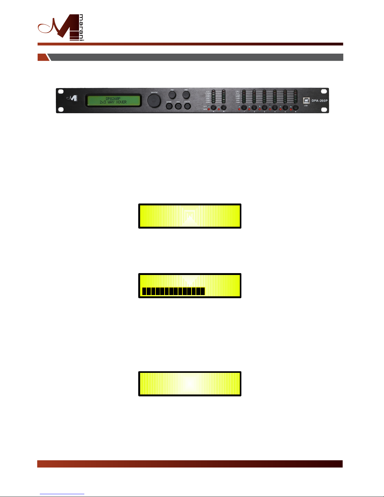
As soon as the DPA240P is turned ON the device model name will appear in the LCD screen:
and a status bar will show the progress of the DPA240P initialization process:
The DPA240P has three factory pre-set working modes:
After the initialization, the DPA240P will show on the LCD the first of the embedded preset
working modes, or the last one selected prior to the unit being turned off.
First time activation will default to the first of the preset working modes.
DPA240P
Speaker Management
1x2 WAY XOVER
DPA240P
DPA240P
2 In - 4 Out Speaker Management System
Ti p Wizar d
“1x 2 Wa ys Xover” and
“4 Ways X over”

Encoders and ENTER, ESC buttons
The DPA240P is equipped with 3 Relative Encoders, “NAV/PM1”, “PM2” and “PM3”, These
encoders allow you to navigate the user interface and edit sections of the processor. They allow
the user to navigate within the screen for the selection of sub-menus, pages and parameters and
to select the values to be assigned during the editing operations.
The “ENTER” and “ESC” buttons allow the user to confirm or NOT confirm the operations
performed by the encoders.
The UTILITY button allows the User to enter the Sub-menus and set the general characteristics of
the Processor. The A and B buttons allow the User to enter the Editing Menus of the Processor's
Input Channels and buttons 1, 2, 3 and 4, allow the User to enter the Editing Menus of the
Processor's Output Channels.
The A and B buttons as well as the 1, 2, 3 and 4 buttons have double functions dependent
on the push and hold time.
When the A and B buttons are pushed and held for more than one second Input Channels A or B
are either muted or unmuted. The red LED will illuminate when the Channel is muted. When the
“MUTE” LED is OFF, then the related Input Channel is UN-MUTED.
A momentary push of the A and B buttons enters the Editing Mode for the Input Channels (see
later for the Input Channel Editing details).
Th e blue “EDIT” LED will now be ON.
When the 1, 2, 3 and 4 b uttons are pushed and held for more than one second the Output
Channels 1, 2, 3 and 4 a re either muted or unmuted. The red LED will illuminate when the
Channel is muted. When the “MUTE” LED is OFF, then the related Output Channel is UN-MUTED.
A momentary push of the 1, 2, 3 and 4 buttons enters the Editing Menu for the Output
Channels (see later for the Output Channel Editing details). The blue “EDIT” LED will now be ON.
As stated above, the start-up default screen is the following factory preset:
From this point, sub-menus are accessed using the UTILITY”,“A/B”,“1/2/3/4”,“ENTER” and
“ESC” buttons and all parameters and values are navigated by the “NAV/PM1”,“PM2”and“PM3”
encoders. Please refer to the following menu structures:
2x3 WAY XOVER
DPA240P
2 In - 4 Out Speaker Management System
UTILITY, A/B and 1/2/3/4/5/6 buttons
DPA240P Menu and Sub-Menu Structures

MENU “UTILITY MENU” [Access by pushing the “UTILITY” button]
NAV/PM1 Encoder PM2 or PM3 Encoder
[to navigate between menus] [to chose option, then ENTER to load it;
(*) indicates the selected option]
1 UTILITY MENU:......
<< System Utilities >>
1.1 SYSTEM UTILITY: System Setup
<< System Setup >>
Setup: 1x2 WAY XOVER
Setup: 4 WAY XOVER
1.2 SYSTEM UTILITY: Delay Units
<< Delay Units >> Unit: Time(ms) *
Unit: Distance (m)
1.3 SYSTEM UTILITY: Software Version
<< Software Version >> Version: V1.02 *
2 UTILITY MENU:......
<< Program Utilities >>
2.1 PROGRAM UTILITY: Recall a Program
<< Recall a Program >> 01: Preset 01
: :
48: Preset 48
2.2 PROGRAM UTILITY: Save a Program
<< Save a Program >> 01: Preset 01
: :
2.3 PROGRAM UTILITY: Delete a Program
<< Delete a Program >> 01: Preset 01
: :
3 UTILITY MENU:......
<< Interface Utilities >>
3.1 INTERFACE UTILITY: Interface Setup
Interface Setup Source: USB
Source: RS485 *
4 UTILITY MENU:......
<< Security Utilities >>
4.1 SECURITY UTILITY: Parameter will
Show Parameter be shown *
not be shown
4.2 SECURITY UTILITY: Lock Unit
Lock Unit L ock: Off *
Lock: On
4.3 SECURITY UTILITY: User Password
User Password [ ]
4.4 SECURITY UTILITY: Enable Password (For the details about the Password Setting/Enable
Enable Password Password: Enable and Unit Lock, , refer to the “ Utility Menus Use ”
Password: Disable * Section)
ENTER
ESC
ENTER
ESC
ENTER
ESC
ENTER
ESC
ENTER
ESC
ENTER
ESC
ENTER
ESC
ENTER
ESC
ENTER
ESC
ENTER
ESC
ENTER
ESC
ENTER
ESC
ENTER
ESC
ENTER
ESC
ENTER
ESC
ENTER
ESC
48: Preset 48
48: Preset 48
2 In - 4 Out Speaker Management System

MENU “Input A/B” Input Channels Editing [Access by pushing the “A/B” buttons]
NAV/PM1 Encoder NAV/PM1 Enc . PM2 Enc. PM3 Enc.
[to navigate between menus] [to chose values for the parameters, no need to confirm the chosen values,
which are automatically loaded during the encoders use]
3. Input A/B Gain
Gain = + 0.0 dB
-> Gain = + 0.0 dB PM1 N/A -15 db Same as Pm2
:
+15 dB
4. Input A/B Delay
Delay = 0.000 ms
-> Delay = 0.000 ms PM1 N/A 000.0000mS 000.0000mS
[1 ms steps] [20.8 us steps]
399.0
000mS 000.9984mS
[Freq.]
20Hz [amp.] -----dB
: :
20kHz
ENTER
ESC
ENTER
ESC
1. Input A/B
[Name] Name
Name=[Name]
-> Name = - (For Editing the Device's Name,refer to the Details on the "Utility Menus USE" Section)
ENTER
ESC
2. Input A/B
[Name] NGate
Noise Gate=off
->Noise Gate=off/on
ENTER
ESC
5. Input A/B [Name] EQ Byp
EQ Bypass= off
->
ENTER
ESC
EQ Bypass= off
PM1 N/A off
:
Same as Pm2
6. Input A/B EQ-X(X from 1 to 5)
Bypass= off
->
ENTER
ESC
Bypass= off
on
Type=Y(Y= Peaking_Eq,Hi-Shelv_Q,Lo-Shelv_q,All Pass_2)
Type=Y
PM1 N/A off
:
Peaking_Eq
on
:
Notch Filt
6.1 Input A/B EQ-X(X from 1 to 5)
Bypass= off
ENTER
ESC
6. 1a. I f se le ct ed a Pe ak ing _E q fi lt er, the n th e fi lte r ca n be s et b y
th e fol lo wi ng p ara me te rs
In put A /B E Q- [x ] (up t o 5 fi lt er s ava il ab le )
[F req ] [G ai n] [ Q]
-> 1 000 Hz 0 .0 dB Q =1. 00
6. 1b. I f se le ct ed a Hi -S he lv _Q (v ar ia bl e Q Hig h Sh el vin g) f il te r,
th en th e fi lt er c an be s et b y th e fo llo wi ng p ara me te rs
In put A /B E Q- [x ] (up t o 5 fi lt er s ava il ab le )
[F req ] [G ai n] [ Q]
-> 1 000 Hz 0 dB Q =1 .00
6. 1c. I f se le ct ed a Lo -S he lv _Q (v ar ia bl e Q Low S he lv ing ) fi lt er,
th en th e fi lt er c an be s et b y th e fo llo wi ng p ara me te rs
In put A /B E Q- [x ] (up t o 5 fi lt er s ava il ab le )
[F req ] [G ai n] [ Q]
-> 1 000 Hz 0 dB Q =1 .00
6. 1d. I f se le ct ed an A ll -Pa ss _2 (s ec on d or der, va ri ab le Q A ll Pa ss) f il te r,
th en th e fi lt er c an be s et b y th e fo llo wi ng p ara me te rs
In put A /B E Q- [x ] (up t o 5 fi lt er s ava il ab le )
[F req ] [G ai n] [ Q]
-> 1 000 Hz - -- -d B Q=1 .0 0
-----dB
[Freq.] 20Hz [amp.] +12dB
: :
20kHz
-12dB
[Freq.] 20Hz [amp.] +12dB
: :
20kHz
-12dB
[Freq.] 20Hz [amp.] +12dB
[Q] 0.3
: : :
20kHz 20.00
-12dB
Th rou gh t he P M2 , it is p os si bl e to By p th e si ng le se le ct ed fi lt er.
Th rou gh t he P M3 , it is p os si bl e to se le ct o ne o f the 4 a va il ab le
fi lte rs ' ty pe .
On ce se le ct ed t he fi lt er Typ e an d NO T in By p mo de , pr ess in g
ag ain t he E NT ER b utt on c an b e ac ces se d th e se lec te d fi lt er' s ed it in g pag e.
[Q] 0.3
:
20.00
[Q] 0.3
:
20.00
[Q] 0.3
:
20.00
2 In - 4 Out Speaker Management System

MENU “1/2/3/4 Output Channels Editing” [Access by pushing the “1/2/3/4” buttons]
NAV/PM1 Encoder NAV/PM1 Enc . PM2 Enc. PM3 Enc.
[to navigate between menus] [to chose values for the parameters, no need to confirm the chosen values,
which are automatically loaded during the encoders use]
1. O ut -[ x] [ Name] H PF
YF = 2 0. 0 H (Y = B yp as s OR Filt er Typ e/ Order, wh er e fi lt er t ype can b e Bu tt w_ 1s t, Bu tt w_ 2n d,
LR il ey _2 nd , Bes se l_ 2n d, B uttw_ 3t h, B ut tw _4th, L ri le y_ 4t h, Be ss el _4 th ,
Lr il ey _6 th , Lrile y_ 8t h, )
-> Y F = 20 .0 H z Freq Fa st S el ectio n [Fi lt Type ] By pa ss [F re q. ] 20 Hz
ON LY in F re q Editi ng M od e : :
Lr il ey _8 th 20k Hz
Th ro ug h th e PM2, it i s po ss ib le t o Bypas s th e fi lt er or to se le ct o ne o f th e 11 avai la bl e
fi lt er s' t ype/o rd er s, a nd t hroug h th e PM 3 to s et the HP c ut ti ng F re quenc y (q ui ck f in e tun in g by 1 Hz s te ps).
On ce s el ec ted the f il te r Type and pr es si ng a ga in the EN TE R bu tt on can be a cc es se d th e sel ec te d
fi lt er 's Fast Fr eq .S el ec tio n pa ge .
2. O ut -[ x] [ Name] L PF
YF = 2 0. 0 Hz ( Y = By pa ss OR Fil te r Type /Orde r, whe re f il te r type ca n be B ut tw _1 st, B ut tw _2 nd ,
LR il ey _2 nd , Bes se l_ 2n d, B uttw_ 3t h, B ut tw _4th, L ri le y_ 4t h, Be ss el _4 th ,
Lr il ey _6 th , Lrile y_ 8t h, )
-> Y F = 20 .0 H z Freq Fa st S el ectio n [Fi lt Type ] By pa ss [F re q. ] 20 Hz
ON LY in F re q Editi ng M od e : :
Lri le y_ 8t h 20kHz
Th ro ug h th e PM2, it i s po ss ib le t o Bypas s th e fi lt er or to se le ct o ne o f th e 11 avai la bl e
fi lt er s' t ype/o rd er s, a nd t hroug h th e PM 3 to s et the HP c ut ti ng F re quenc y (q ui ck f in e tun in g by 1 Hz s te ps).
On ce s el ec ted the f il te r Type and pr es si ng a ga in the EN TE R bu tt on can be a cc es se d th e sel ec te d
fi lt er 's Fast Fr eq .S el ec tio n pa ge .
3. O ut -[ x] [Nam e] E Q By p
EQ B yp as s = Of f
-> E Q By pa ss = O ff PM1 N/A O ff Sam e as P M2
:
On
4. O ut -[ x] [Nam e] E Q- [x ] (X f rom 1 to 5)
By p = Of f Typ e = Y (Y = Peaki ng _E q, H i- She lv _Q , Lo -S helv_ Q, A ll Pa ss _2, )
-> B yp = O ff Typ e = Y PM 1 N/ A Off Pea ki ng _E q
: :
On No tc h Fi lt
Th ro ug h th e PM2, it i s po ss ib le t o Byp the s in gl e se le cte d fi lt er.
Th ro ug h th e PM3, it i s po ss ib le t o selec t on e of t he 4 a vaila bl e
fi lt er s' t ype.
On ce s el ec ted the f il te r Type and NO T in B yp m od e, p ressi ng
ag ai n th e EN TER but to n ca n be a ccess ed t he s el ec ted fil te r' s ed it ing p ag e.
4. 1 Ou t- [x ] E Q- [x] (X fr om 1 t o 5)
-> B yp = O ff Typ e = Y
4. 1a . If s el ected a Pe ak ing _E q fi lt er, th en the fi lt er c an b e se t by
th e fo ll ow ing par am et er s
Ou t- [x ] EQ -[ x] ( up t o 5 filte rs a va il ab le)
[F re q] [ Ga in] [Q]
-> 1 00 0H z 0d B Q= 1.0 0 [ Fr eq.] 20 Hz [Amp. ] +1 2d B [Q ] 0. 30
: : :
20 kH z -1 2d B 20 .0 0
4. 1d . If s el ected a H i- Sh el v_ Q (vari ab le Q H ig h Sh elvin g) f il te r,
th en t he f il ter can b e se t by t he f ol lowin g pa ra me te rs
Ou t- [x ] EQ -[ x] ( up t o 5 filte rs a va il ab le)
[F re q] [ Ga in] [Q]
-> 1 00 0H z 0d B Q= 1.0 0 [ Fr eq.] 20 Hz [A mp .] + 12 dB [Q ] 0. 30
: : :
20 kH z -1 2d B 20 .0 0
2 In - 4 Out Speaker Management System
ENTER
ESC
ENTER
ESC
ENTER
ESC
ENTER
ESC

4. 1g . If s el ected a Lo- Sh el v_ Q (vari ab le Q L ow S he lv ing) fi lt er,
th en t he f il ter can b e se t by t he f ol lowin g pa ra me te rs
Ou t- [x ] EQ -[ x] ( up t o 5 filte rs a va il ab le)
[F re q] [ Ga in] [Q]
-> 1 00 0H z 0d B Q= 1.0 0 [F re q. ] 20Hz [Amp .] + 12 dB [Q ] 0.30
: : :
20kH z -12dB 20 .0 0
4. 1q . If s el ected a n Al l- Pas s_2 ( se co nd o rd er, varia bl e Q Al l Pas s) filt er,
th en t he f il ter can b e se t by t he f ol lowin g pa ra me te rs
Ou t- [x ] EQ -[ x] ( up t o 5 filte rs a va il ab le)
[F re q] [ Ga in] [Q]
-> 1 00 0H z -- -- dB Q= 1. 00 [Fr eq .] 2 0H z [A mp .] ----dB [Q] 0 .3 0
: : :
20 kH z -- -- dB 20 .0 0
5. O ut -[ x] [ Name] Vu -M et er
Vu- Me ter = Level
-> Vu -M eter = Leve l PM1 N/ A L ev el Same as P M2
Limi te r Ac t.
RMS Cm p Ac t.
6. O ut -[ x] [ Name] N am e
Na me = [ Na me ]
-> N am e = _ (For E di ting th e De vi ce 's N ame, re fe r to t he D etail s on t he “U ti lity Me nu s Us e” S ec tio n)
7. O ut -[ x] [ Name] S ou rc e
So ur ce = I nA
-> S ou rc e = In A PM1 N/A . In A (C hanne l A) S am e as P M2
In B (C ha nn el B )
In A+ In B (C ha nnel A+ C ha nn el B )
8. O ut -[ x] [ Name] G ai n
Ga in = + 0 .0 d B
-> G ai n = + 0. 0 dB P M1 N /A - 15 d b Sa me a s PM 2
:
+1 5 dB
9. O ut -[ x] [ Name] L im it er
A: 5 ms R : 0. 2s + 16 dB
-> A : 5m s R: 0 .2 s +1 6dB [Atk ti me ] 5m s [Rel ti me ] 0. 1s [Amp .] - 14 .0 d B
: : :
20 0m s 3 .0 s +1 6d B
10 . Ou t- [x ] [Name ] De la y
De la y = 0. 00 0 ms
-> D el ay = 0 .0 00 ms PM1 N/A 00 0.000 0m S 0 00 .0 00 0mS
[1 m s st ep s] [ 20 .8 u s ste ps ]
399 .0 00 0m S 00 0. 99 84 mS
11 . Ou t- [x ] [Name ] Pol arity
Pol arity = N or ma l
-> Po larit y = No rm al P M1 N /A Norm al Sa me a s PM 2
In ve rt
2 In - 4 Out Speaker Management System
ENTER
ESC
ENTER
ESC
ENTER
ESC
ENTER
ESC
ENTER
ESC
ENTER
ESC
ENTER
ESC

Menu “UTILITY” [access by pushing the “UTILITY” button]
From the “Default Screen”, it is possible access the“UTILITY”menu pushing the“UTILITY”button
and the Sub-Menus pages can be selected just rotating clockwise and counter-clockwise the
“NAV/PM1” encoder.
Once selected the sub-menu page, using the “ENTER” button can be accessed the Sub-Menus
pages, again “scrollable” using the “NAV/PM1” encoder and accessible for the parameters' editing
pushing again the “ENTER' button.
Through the “ESC” button, it is any time possible to go back to the action and page preceding the
“ENTER” button use.
Once inside the Sub-Menus pages, the several options can be scrolled and using the PM2 or PM3
encoders and selected/confirmed pushing the “ENTER” button.
Note : In every Sub-Menu the option currently selected/running will have an asterisk “ *
” showing
to the right of the description on the LCD screen.
Options that are not selected/running will be displayed with NO Asterisk.
Pushing the ENTER button on an unselected option will mean an asterisk will then appear and this
option will now take over as the currently selected/running option.
System Utilities Sub-menu
– this sub-menu allows to access several operations related to the
DPA240P Start Up and General Configuration:
From the “System Utilities Sub-menu”, pushing “ENTER”and then using the“NAV/PM1”encoder
for scrolling will give access to the following pages:
– System Setup: this page allows the selection of the operating mode of the DPA240P :
The operating mode can be chosen from a selection of 3 Xovers options :
2x2 WAY + SUB ...........
in this operating mode, the DPA240P is performing a 2 Input to 4
Outputs X-Over, plus a SUB configuration, where the 2 Inputs are automatically assigned to
the Outputs as follows:
– Input A to Outputs 1/3 [Out1=Low-A and Out3=High-A]
– Input B to Outputs 2/4 [Out2=Low-B and Out4=High-B]
SYSTEM UTILITY
– System Setup --
UTILITY MENU
– System Utilities --
2 In - 4 Out Speaker Management System
6 WAY... XOVER .......
in this operating mode, the DPA240P is performing a Mono Input to 6
Outputs X-Over, where the Input A is automatically assigned to the Outputs as follow:
–
Input A to Outputs 1/2/3/4 [Out1=Near-1, Out2=Near-2, Out3=Mid-1
and Out4=Mid-2]

By pressing ENTER on the System Setup page and rotating the“PM2”or“PM3”encoder, it
is possible to select all the available X-Over preset modes.
When the “1x2 WAY XOVER” is selected, the “System Setup” page will appear as follows
:
To change the desired operating mode for the DPA240P, the screen must reflect the xover
required and then simply pressing the “ENTER” button will bring up the following screen asking
for confirmation to load the selected operating mode:
If confirmed by pressing ENTER the selected preset mode will load. While the device is
configuring the Xover the following screen will be appear
The new preset mode will now be shown with an asterisk.
New Xover
[ENTER] to confirm
:
Please Wait .....
Changing Xover
System Setup
Setup: 1x2 WAY XOVER *
2 In - 4 Out Speaker Management System
– Delay Time/Distance:
this page allows you to select the measurement unit to be used for
the Delays: Time (in milliseconds “ms”) or Distance (in meters “m”):
By pressing ENTER and rotating the “PM2” or “PM3” encoder, it is possible to select the
measurement unit to be used for the delay, which will be confirmed by pushing the ENTER
button.
The following screen shows the selected delay measurement is Time (milliseconds)
– Software Version:
this page allows you to confirm the Software Version running on the
DPA240P:
SYSTEM UTILITY
-- Delay Units --
Delay Units
Unit : Time (ms) *
SYSTEM UTILITY
– Software Version --
The correct Software Version is “V1.02”

Program Utilities Sub-menu
– this sub-menu allows you to access several options related to
the DPA240P operating mode and to manage the presets stored and recallable within the Unit:
By pressing the ENTER button and then using the “NAV/PM1” encoder the following pages can be
accessed:
– Recall a Program:
this page allows the Loading of a preset program. You can store up to 48
presets in the DPA240P memory:
By pressing ENTER and rotating the“PM2”or“PM3”encoders, it is possible to scroll through all
current available user presets.
If NO USER PRESETS are stored yet, the screen will show the following:
If presets have previously been stored by the user, anyone of them can be recalled:
By using the“PM2”or“PM3”encoder it is possible to scroll through the stored presets. Once
the desired preset appears on the screen select it by pressing the “ENTER” button and this will
force the DPA240P to begin to load this selected preset and the following transitory screen
will appear:
Once loaded the DPA240P will exit to the “Recall a Program” screen automatically and the
above screen will disappear:
Note : at any time it is possible to quit the recall action by pressing the “ESC” button.
UTILITY MENU
-- Program Utilities --
Recall a Program
No Stored Xovers.
[ENTER] to Recall.
01: PRESET 1
Loading New Program ......
01: PRESET 1
PROGRAM UTILITY
– Recall a Program --
PROGRAM UTILITY
– Recall a Program --
2 In - 4 Out Speaker Management System
 Loading...