

Marani CLP-260 User Manual
19"
482mm
DIGITAL
USB

Index
Index........................................................................P age 1
Safety Instructions................................... ..................Page 2
Controls and Parameters......................... ...................Page 3
CLP260 Processes Notes.......................... .................Page 4
RMS Compressor............................ ..........Page 4
A.G.C............................................... .......Page 5
PEAK Limiter................................... .........Page 6
Sub Harmonic Synthesizer.........................P age 7
Input and Output Level Considerations........................P age 8-10
Getting Started..........................................................P age 11
Encoders and ENTER/QUIT buttons............................P age 12
Load/Save Preset......................................................P age 12-14
Utility Function..........................................................P age 15
Edit Parameters........................................................ Page 16
Routing....................................................P age 16
Input Gain................................................ Page 16
Noise Gate...............................................P age 16
A.G.C.......................................................P age 17-20
Filters 1-7.................................................P age 21
Sub Harmony............................................P age 22
Drive........................................................P age 23
RMS Compressor......................................P age 24-25
Make Up.................................................. Page 25
PEAK Limiter............................................P age 26
Mute........................................................ Page 26
Appendix 1............................................................... Page 27
Input Level Meters Ref. Table.....................P age 27
Comprressor/Limiter Activity......................P age 28-29
Meters Ref. Table......................................P age 29
CLP260 Processes Block Scheme...............................P age 30
1
IMPORTANT SAFETY INSTRUCTIONS
Ventilation
1
Overload
5
Heat sources
3
Power cord proctecion
4
2
Maintenance
8
7
Humidity
Cleaning
Note: inordertoensuresafety,pleasereadtheseinstructionscarefully
Attention:To reduce the riskoffireorelectricshock,donotexpose this apparatus
torainormoisture!
All safety and operating instructions should be read before the
product is operated.
6
Objects or liquid entry
inside the unit
Refer all servicing to
qualified service
personnel. To
prevent the risk of
shock, do not
attempt to service
this equipment
yourself because
opening or removing
covers may expose
you to
dangerous voltage
or other hazards.
The unit should far
away form water.
Be careful tha t no
objects fall or liquid is
spilled inside the unit
th r o ugh venti l a tio n
openings.
Do not block any
ventilation openings.
Clean only with dry
cloth.
Do not install near
any heat sources
such as radiators,
stoves, or other
apparatus that
produce heat.
Protect the power
cord from being
walked on or pinched
particularly at plugs.
Power plug should
not overload.
2

1
3
CLP-260
RMS StereoCompressor
CONTROLS
Enc Variation Adjust Parameters Value
Key Enter Access to Editing Pages and Par Values Confirm
Key Quit Exit from Editing Pages
Led Clip Input/Process Overflow
Enc Navigation Compressor's Ratio and Knee selection
Button Process On/Off RMS Compressor Active/Bypass
Pot Input Level Analog Input Gain Left/Right
Pot Output Level Analog Output Volume Left/Right
TECHNICAL DATA
Inputs Balanced 2 TRS/2 XLR
Outputs Balanced 2 TRS/2 XLR
Input Max Level +15dBu
Output Max Level +10dBu
THD+N <0.01% @ -6dBFS (Bypass)
S/N Ratio >100dBu (Processes in Bypass)
Frequency Response 20Hz – 20kHz +/-0.5dB
A/D and D/A Resolution 24bit
Process Resolution 24x48 bit
Processes RMS Stereo Compressor
Power Supply 110V/220V (Switchable)
2x20 characters LCD display for the Parameters Editing
Fully remotely controllable by USB or MIDI interfaces
4
The CLP260 is a Stereo RMS Compressor and Peak Limiter with the
addition of a Noise Gate, an AGC, a 7 bands Eq and a Sub Harmonic
Synthesizer.
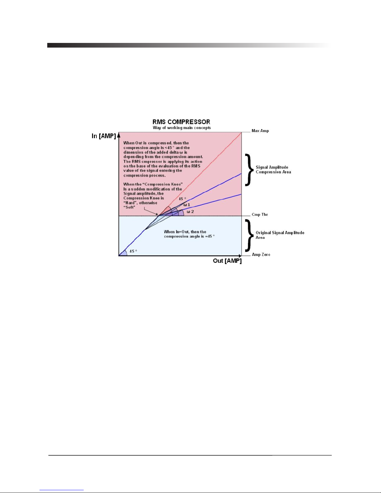
W i th ref e r e nc e to th e fo l lo w in g R M S C o m p re s si o n p ro c es s
representation
The CLP260 is implementing a REAL RMS Compressor, so compressing
at the same threshold a pure sinusoidal signal as a squared wave.
Particularly, the RMS Compressor is a Compression process applied with
fast slow Attack and Release times to the INPUT signal of a Unit, in order
to maintain the amplitude of the OUTPUT signal at a defined level, when
input level is exceeding a defined intervention Threshold.
The Compressor implemented in the CLP260 is acting on the evaluation
of an input signal which is an averaged one on a 50ms time frame, and
representing actually the RMS value of the input signal itself, so to make
more “Musical” the Compressors action. The RMS Compressor, it is so
maintaining constant the output energy and not the Output peak, so to
have for the different inputs, independently from their harmonic content,
a constant output RMS level.
More, for the CLP260 Compressor is also available a Ratio and a
Hard/Soft Knee parameters. The Ratio parameter is allowing to get a
compressed output maintaining a constant dB ratio with the input.
This feature is got in the CLP260 with a precise Look Up Table Log
Computation process, allowing int the ratio maintenance a precision of
0.1dBu.
5
The Hard and Soft knee feature is allowing the user to select between a
sudden compression intervention when the input signal it is just above
the Threshold (Hard Knee) or a smoother one starting the compression
smoothly before the Threshold.,
Together with the RMS Compressor, the CLP260 is making available also
other 2 very useful Dynamic Processes: an AGC and a Peak limiter.
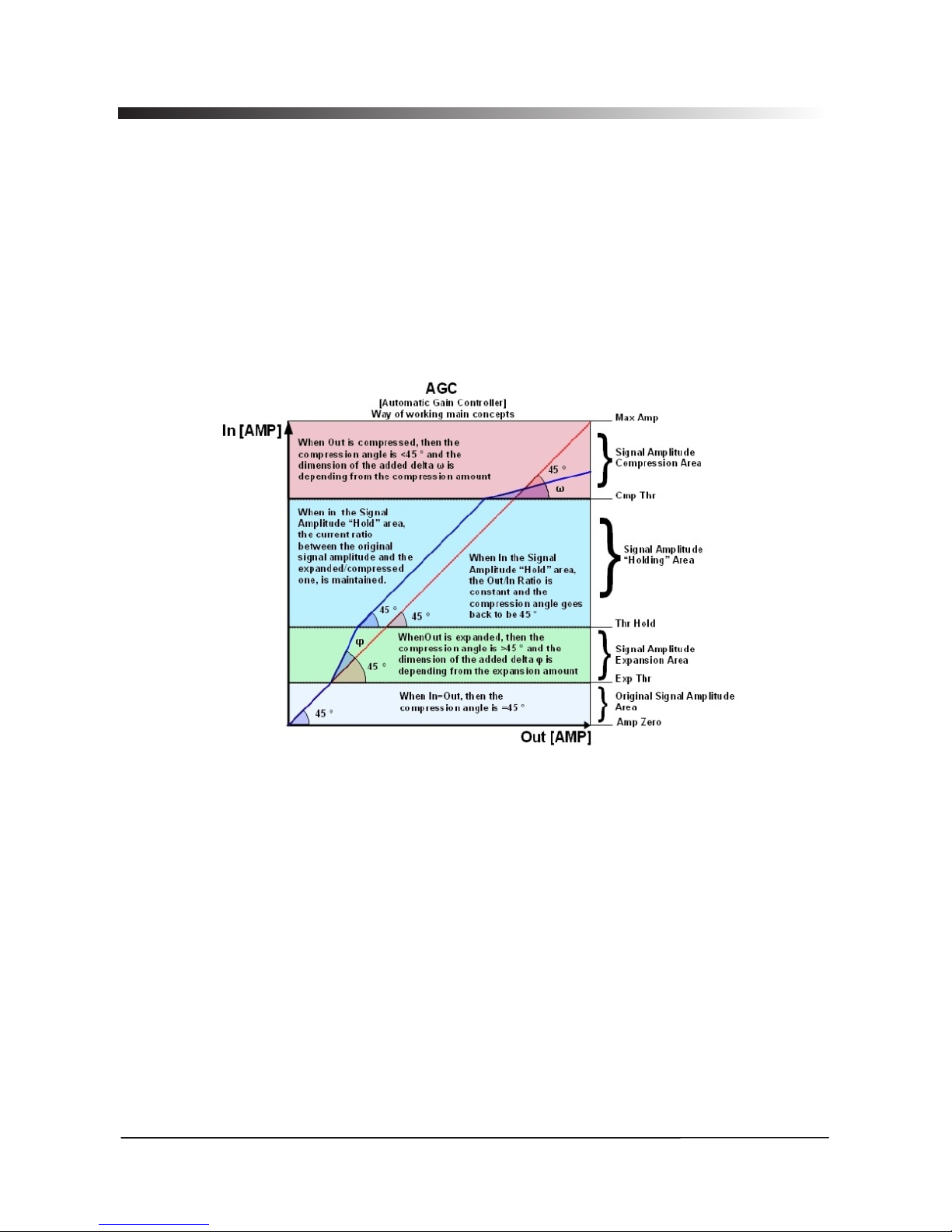
In order to understand how the CLP260 AGC is working, need to refer to
the following picture
The AGC is an Expansion/Compression process applied with pretty slow
Attack and Release times to the INPUT signal of a Unit, in order to
maintain the average amplitude of the OUTPUT signal at a defined level,
independently from the averaged amplitude of the input sources.
For this purpose, the AGC has to be able to expand the input signal, there
where the average of the related output signal is below a defined
Threshold (Exp Thr), and to maintain the expanded signal at a constant
expansion level when the averaged signal is beyond a defined Threshold
(Thr Hold).
The AGC implemented in the CLP260 is acting on the evaluation of an
input signal which is an averaged one on a 50ms time frame, and
representing actually the RMS value of the input signal itself, so to make
more “Musical” the AGC action.
If the output signal of the AGC process will exceed then a defined
Threshold (Cmp Thr), so becoming too loud, a compression process is
occurring.
6
The Speed and the amount of the Expansion can be defined through the
“Exp Time' and “Exp Ratio” parameters, so as the Speed and the amount
of the Compression can be defined through the “Cmp Time” and “Cmp
Ratio” parameters.
When the Signal coming out from the AGC process (Output), applied to
the AGC input, is above the “Exp Thr” and below the “Thr Hold”, it is
expanded up to the max expansion coefficient defined by the Exp Ratio.
When the Signal coming out from the AGC process (Output), applied to
the AGC input, is above the “Cmp Thr”, it is compressed up to the min
compression coefficient defined by the “Cmp Ratio”.
When the AGC output is comprised within the “Thr Hold” and the “Cmp
Thr” Thresholds, no further expansion or compression actions will be
taken and the expansion/compression coefficient, will be maintained with
its current value.
Particularly, if the averaged AGC output level is “entering” the signal
“hold” area coming from the expansion area, then the Coefficient
computed by the AGC for multiplying the input level in order to get the
proper output signal, will be higher than one (if the “Exp Ratio” will be set
at 1:2), so as the coefficient will be lower than one (if the “Cm Ratio” will
be set between 2:1 and 16:1) if the averaged AGC output level is
“entering” the signal “hold” area coming from the compression area.
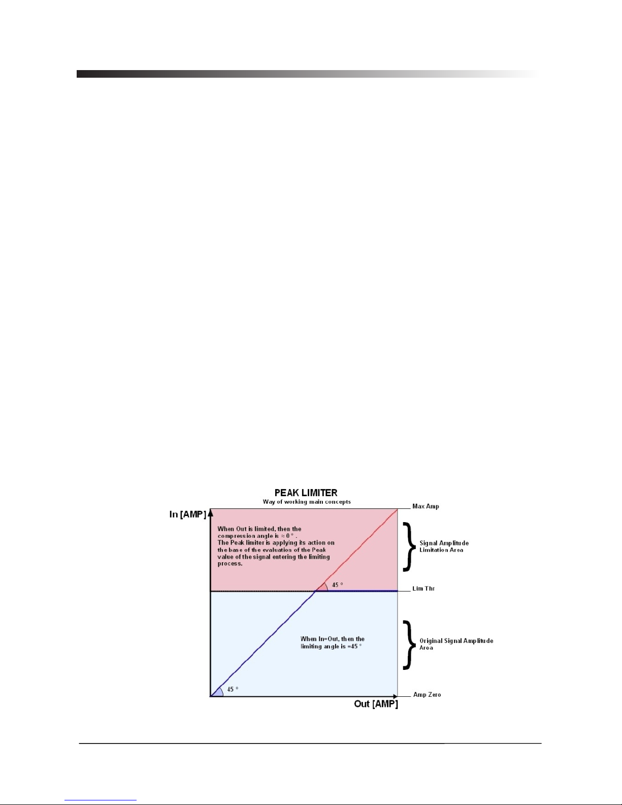
The last dynamic process available with the CLP260, is a Peak Limiter,
useful when the CLP260 is used before an amplifier and need to limit the
signal for avoiding the amplifier to overload and break cabinets.
This kind of Limiter is acting on the Signal Peak detection and therefore
the limitation is on the output Peak value.
7
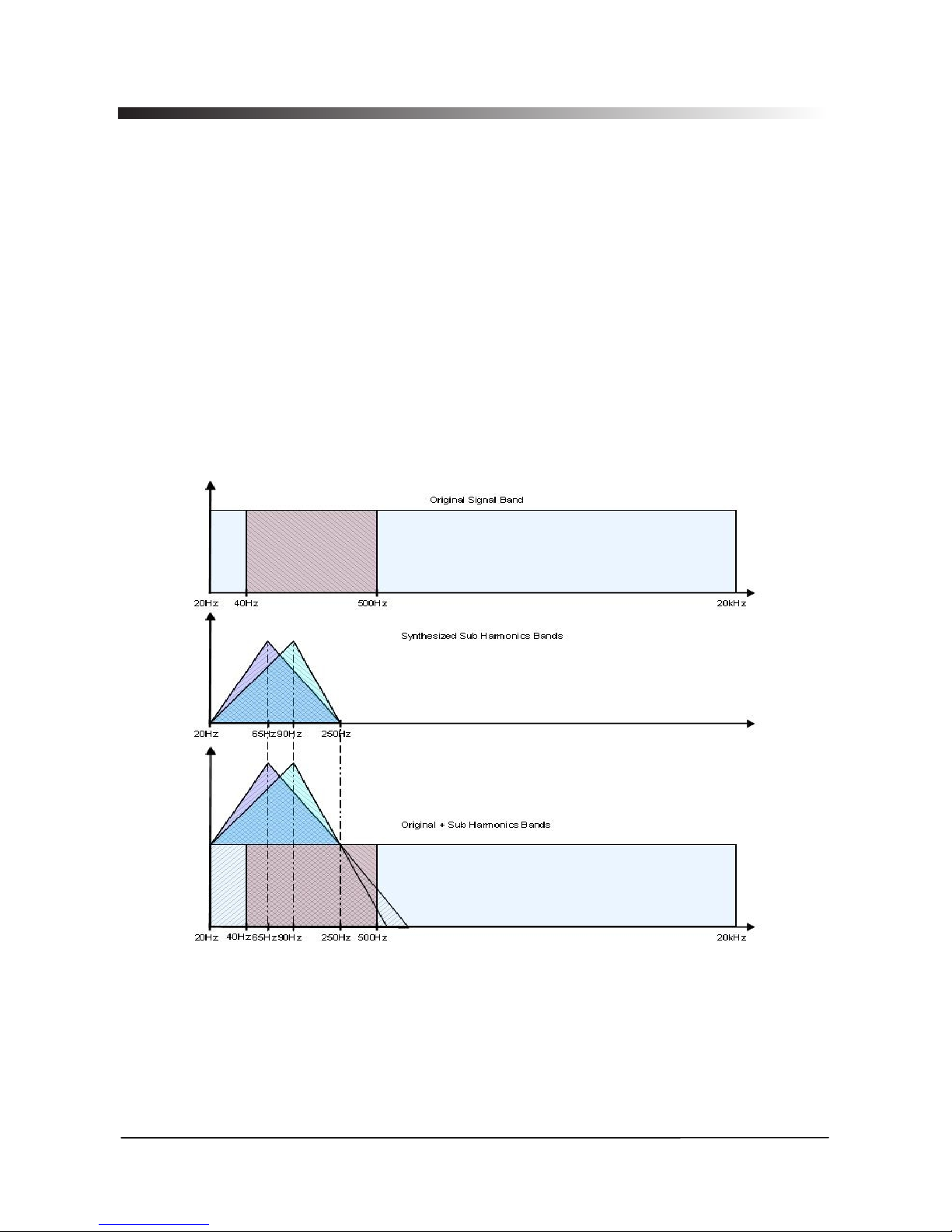
In addition to the Dynamic Processes, in the CLP260 is also available a
powerful Sub Harmonic synthesizer.
The Sub Harmonic Synthesizer is working generating sub Harmonics on
the base on the Harmonic content of the original signal.
Particularly, the amplitude distribution of the generated Sub Harmonics is
following the shape of a band pass filter set on the low part of the band.
The peak of this “band pass” filter, is centered on 2 possible frequencies,
60Hz and 90Hz.; this means that when selected the frequency range
setting the Sub Harmonics Amplitude Peak on 60Hz (24-36Hz), the
Harmonics added to the original sound will bring a “deep” and very low
extra body to the original sound.
When selected the frequency range setting the Sub Harmonics Amplitude
Peak on 90Hz (36-56Hz), the Harmonics added to the original sound will
bring a “lighter and more booming” extra body to the original sound.
Finally, in order to “adjust” harmonically the Input signal, a 7 bands Eq. is
available, where the first of the 7 filters can be chosen to be 1st/2nd ord.
HP or Low Shelving, the seventh one can be chosen to be 1st/2nd ord. LP
or High Shelving and the other 5, from the second to the sixth, can be
chosen to be 1st/2nd ord. High Shelving or Peaking.
The CLP260 has a bypass control in the analog domain.
8
Input and Output Level Considerations
The Input and Output levels of the CLP260 can be adjusted by a couple of
Analog Potentiometers.
Due to the fact that the potentiometers are operating in the analog
domain, before the A/D converter ( Input Level) and after the D/A
converter (Output Level) there is not an absolute and fixed relation
between the Input and Output Levels and the levels in front of the A/D and
after the D/A converters.
Need therefore to provide the user some “Absolute” reference in terms on
Input level and Output level, in order to clarify first what are the Max
Absolute Input level, which cannot be exceeded without getting an OpAmp clip, no longer recoverable by any Digital operation.
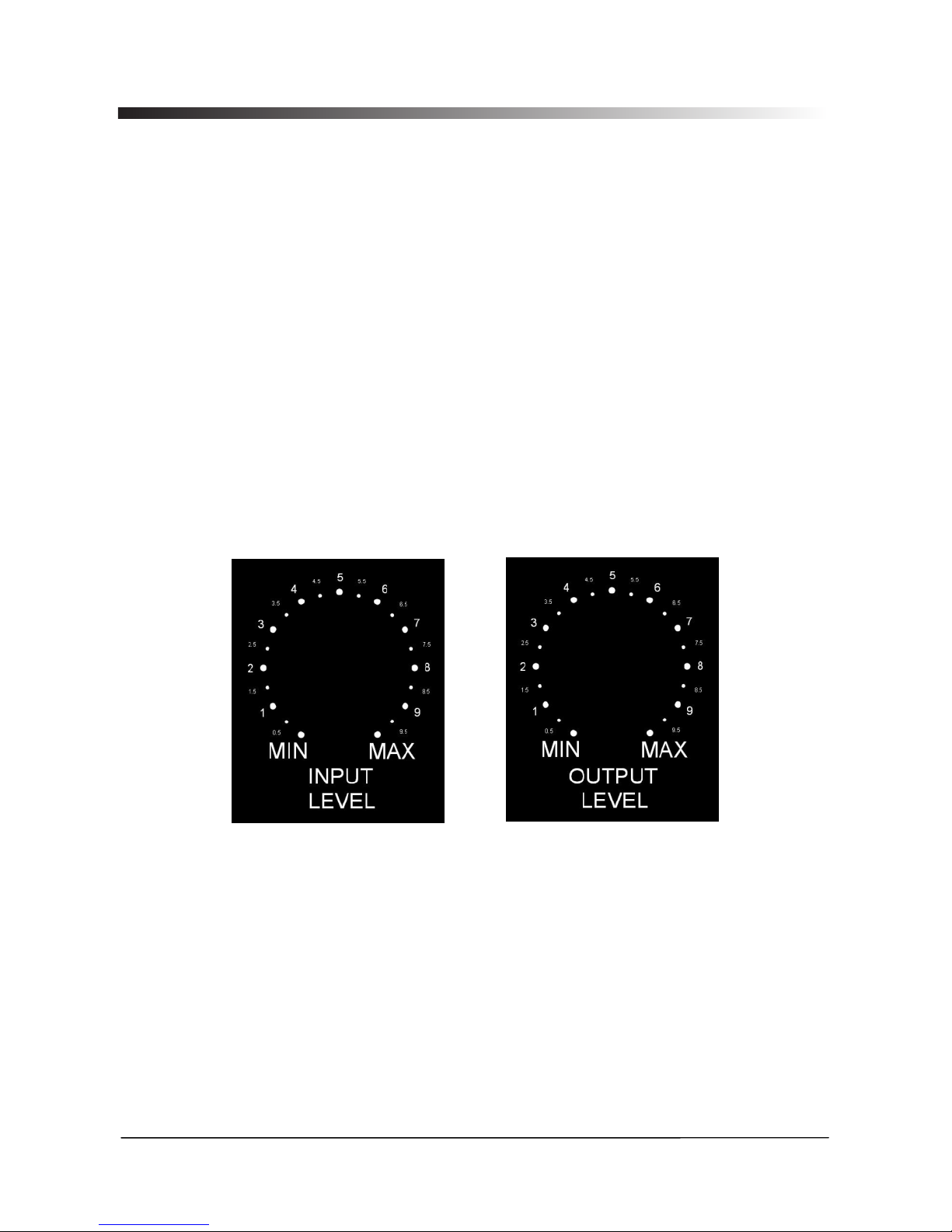
In order to help the user in understanding clearly the following
paragraphs, need to refer to the “Input Level” and “Output Level” pictures,
replicating the Input and Output Potentiometers' grids with a more
precise detail:
Fig A Fig B
The figures A/B are showing in details the possible positions of the
potentiometers controlling the Analog Input and Output Level.
Referring then to the above precise divisions of the available range
between the MIN and MAX position of the potentiometers, the Max Analog
Input/Output levels can be understood, so as the can be found the proper
setting for the best use of the RMS Compressor.

9
In order to verify the Input/Output Max Levels of the CLP260, need first to
make sure that NO process is active.
Max Analog Input: in order to understand what can be the maximum
Analog Input level to the unit, which is the one before the clipping of the
Op-Amps in front of the A/D converters, need to make sure that no Digital
clip (DSP process) is occurring.
The output will never clip unless the clip is coming from the digital
process.
This means that if the D/A output isn't clipped, then no clipping will come
from the Analog Op-Amp output section.
From this point of view, any position of the Output potentiometer for
evaluating the Max Input level, can be set.
Let's consider to set the output potentiometer to the position 5 of the grid
in Fig B.
Now, to define what is the Max Analog Input level, need to set the Input
Level potentiometer to a position granting enough attenuation of the
signal before the A/D, so to make sure no clip is occurring on the A/D side.
Let's set the Input potentiometer to the position 3 of the grid of Fig. A.
Done this, we can increase progressively the Input signal level until the
output will start to clip or the Input Level displayed on the LCD will not
show the “>” symbol.
In this way, can be found that the Max Input level, before to get the Input
Op amps clipping is +15dBu.
Max Analog Output: once set the Max Input Level to +15dBu, in order to
identify the Maximum Output Level, need to move the Input Level
Potentiometer from the position 3, up to the position that is clipping the
A/D converter.
With +15dBu Input, the position of the Input Level Potentiometer at the
limit of the Input Clipping, is the position 6 of the Input Level grid of Fig A.
Once set, then, the Input Level Potentiometer to the position 6, in order to
find out the Max Output Level achievable with the CLP260, need to set
the Output Level Potentiometer to the position Max
The Max output Level that can be found is +10dBu, if measured with an
Audio Precision or similar measurement tools.
CLP260 Signal to Noise Ratio (S/N): from the condition got for the Max
Analog Output verification, can be go the S/N of the CLP260.
If, with the Max Output Level of +10dBu, the Input Signal Is removed,
measuring the output can be seen that the residual Ground Floor Noise
drops to -92.7dBu, which let us say that the S/N=(Max Output) – (GND
Floor Noise) = 10dBu - (-92.7dBu) = 102.7dBu
 Loading...