


Order Code: A78JQ
* Please read fitting instructions carefully
prior to commencing installation.
Fitting and testing instructions
E a s y
Fit Car
A l a r m
ARM DISARM
OPEN
DOOR
INTERIOR
LIGHT
NOW
GOES
ON
ALARM
SOUNDS
INDEX
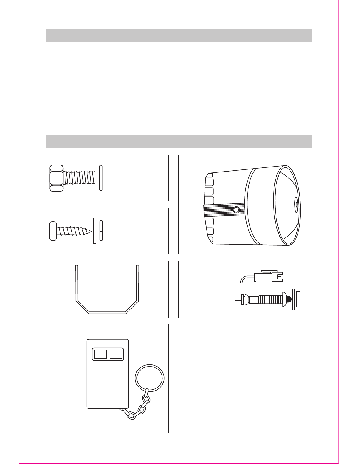
PARTS CONTENTS LIST
1. Parts Content List
2. Alarm Installation
a) Mounting the Alarm
b) Wiring the Alarm
3. Testing Procedures a) Electrical Testing
b) Shock Testing
4. Key Fob Battery Replacement
5. After Sales Support
Bolts/washers x2.
For fixing the
bracket to the
main alarm unit.
Main Alarm
Unit x1
LED with cable
connector, Flat
washer, star
washer and
securing nut all x 1.
Mounting
Bracket x 1
Keyfob x 1
Containing
one
alkaline
battery.
Flat washers/Spring
washers/Screws x3
of each.
For fixing the
bracket to car
ARM DISARM
FOR YOUR SECURITY
The remote conrtol of the alarm is
progrmmed
to work only with this alarm. It will NOT
work with another of the same model of alarm,
or any other alarm.
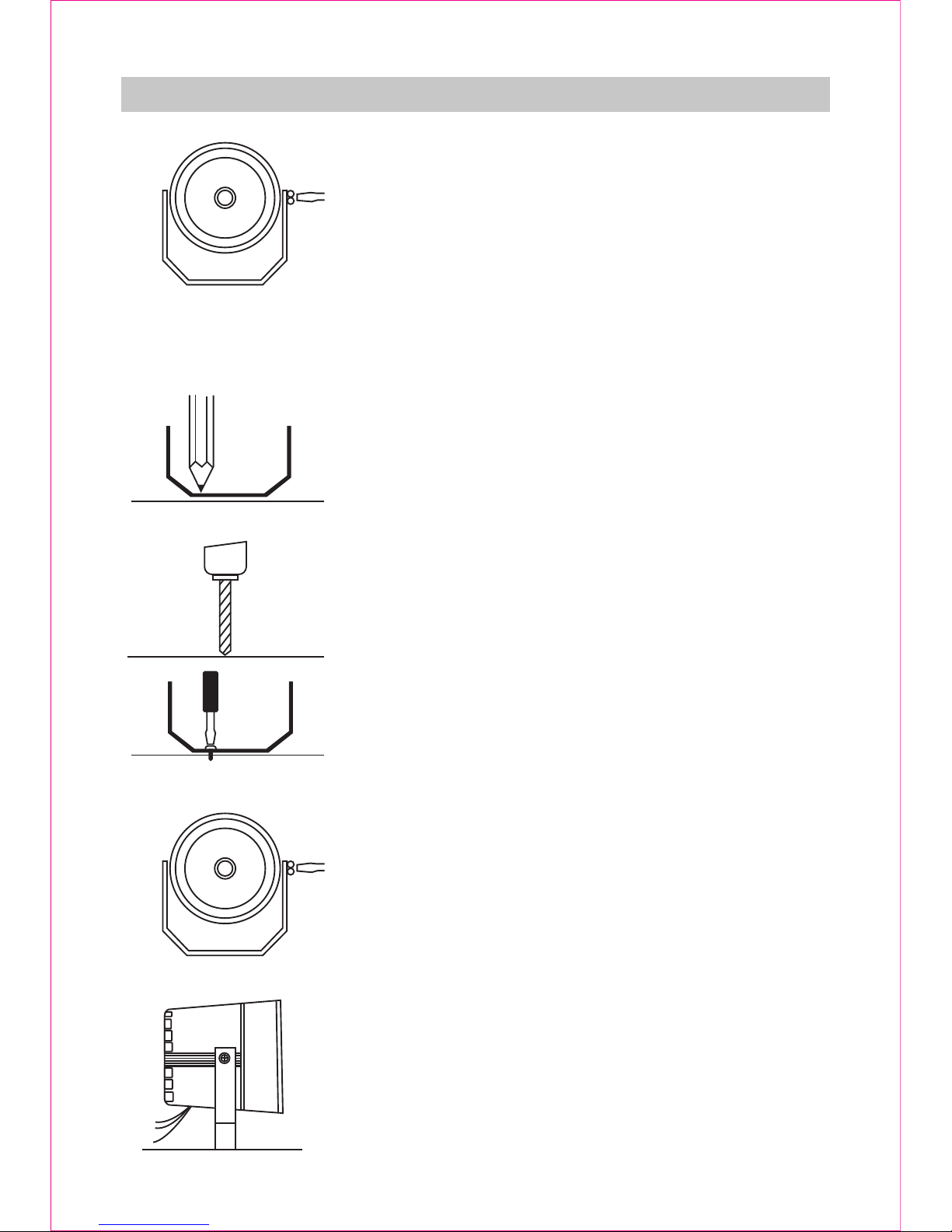
ALARM INSTALLATION
X X
3/32”
A. MOUNTING THE ALARM
To install this sytem you must ensure your vehicle
has a 12V DC negative ground electrical sytem.
1. Remove alarm from metal bracket.
2. Locate a mounting area as high as possible in
the engine compartment allowing space at the rear
to allow for shock sensor adjustment.
WARNING:DO NOT MOUNT NEAR EXHAUST
MANIFOLD OR OTHER HOT EQUIPMENT.
3. With a marking pen, mark the mounting holes for
drilling, using the metal bracket as a template.
4. Drill holes in the locations marked using 3/32”
drill bit.
5. Fix the metal bracket to the car using the screws
provided.
6. Refit alarm to the metal bracket.
7. Adjust the angle of the alarm and tighten the
screws.

B. WIRING THE ALARM
POWER WIRE(RED)
This can be attached to your fuse box, interior light fuse, or directly onto the
POSITIVE terminal of your car battery.
Connecting to fuse box.
Locate the fuse box. From your car Owner’s Manual identify the fuse that
operates the interior light. Attach the bare end of the red wire to this fuse - this
may require use of a connector suitable for use on your vehicle such as a spade
or “Scotchlock” connector. If the fuse box is inside the passenger compartment,
locate an access hole into the car and pass the wire through this hole and then
connect to the fuse box. If no access hole can be found then you will need to drill
your own access hole, but you will need to be careful where you drill.
Connecting direct to car battery.
Run the wire around the engine, making sure it is firmly attached to the car.
Securely attach to the POSITIVE terminal of the car battery, again using a
suitable connector.
NB: When both the black and red wires are connected the alarm will”chirp”. This
is normal and shows the circuit is completed.
AERIAL WIRE(BLUE)
This wire should not be cut. Stretch the wire out and lay it flat around the
engine compartment, avoiding hot areas.Secure the wire to the car by
adhesive tape, or other non-corrosive means.
(RED) (BLUE)
FUSE BOX
OR
BATTERY
TERMINAL(+)
AERIAL AUXILLARY
CONNECTOR
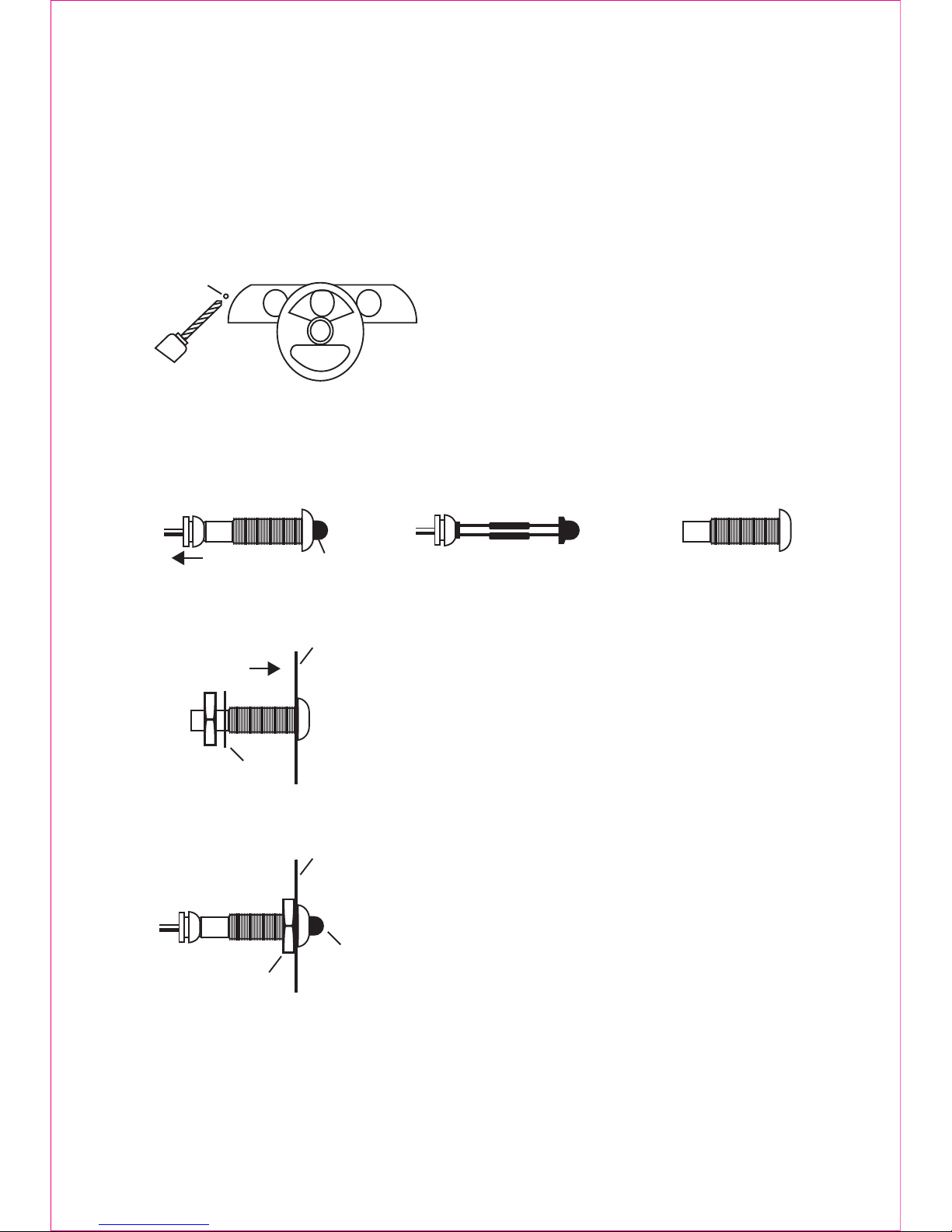
WIRE FOR THE FLASHING RED LIGHT (LED)
Locate a hole into the passenger compartment from the engine compartment,
through which the LED wire will pass. If no hole can be found a new hole will have
to be drilled.
LED HOLDER
PULL
LIGHT
GROMMET HOLDER
TIGHTEN NUT
WASHER
DASHBOARD
FITTING THE FLASHING LED
Locate a point on the dashboard that can
be seen from the outside of the car.
Drill a hole in the dashboard just big
enough to tightly hold the flashing LED
holder (use a 10mm drill bit).
Remove flashing LED from the holder.
Push the LED holder into the dashboard
hole from the front and secure the holder to
the dashboard using the nut provided.
Refit the flashing LED into the holder,
ensuring that the grommet is pushed well
into the back of the holder.
Connect the wire from the LED to the
auxilliary connector.
When the red light is flashing your system
is armed, when it is not flashing the system
is disarmed.
DASHBOARD
FLASHING L.E.D.
NUT AND WASHER
TO ALARM
GROMMET

SETTING UP AND TESTING PRODUCTS
HOW YOUR ALARM WORKS
This alarm is activated by sensing the interior
light coming on, or by sensing a movement of
the vehicle.
NB: If you regularly park on a road which
carries heavy traffic then it is recommended
that you set the shock sensing to a less
sensitive setting to ensure that you do not get a
lot of false alarms.
TESTING YOUR ALARM
A. Current Sensing
The alarm is activated by your interior light
going on when the door is opened. Therefore
your interior light system must work.
To test your alarm, close all the doors, boot and
bonnet. Depress the arm button on the remote
control. You will hear the alarm chirp once, and
the LED will start to flash. Your alarm is now
armed.
After 5 minutes, open one of the doors which
operates the interior light. Your alarm will be
triggered and the siren will sound.
To switch off, press the disarm button. If you do
not press the disarm button, the siren will sound
for approximately 30 seconds and then switch
off. The alarm will then
reset itself so that is armed.
When the alarm is disarmed, close the door
and then re-activate the alarm. Try all the doors
that operate the interior light to make sure that
they all trigger the alarm.
In the normal course of using your alarm, it will
chirp once when you arm the alarm, and twice
when it is disarmed.
OPEN
DOOR
INTERIOR
LIGHT
NOW
GOES
ON
ALARM
SOUNDS
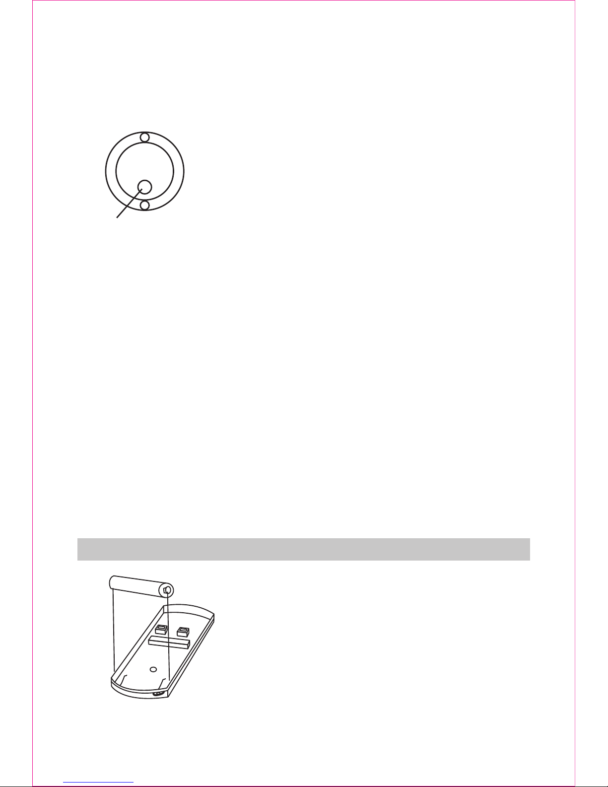
REMOTE CONTROL BATTERY REPLACMENT
B. Shock Sensing
The alarm is activated by a sharp movement of the car.
The sensitivity of the alarm can be adjusted using the
adjustment control on the rear of the alarm. Use your
fingers to turn it. The adjustment control turns
clockwise approximately 3/4 of a turn from minimum
to maximum sensitivity.
TO CHECK THE SHOCK SENSING
Arm the alarm using the keyfob.
Slap the windscreen with your hand - the alarm
should activate. If the alarm does not go off, move the
adjustment control to a more sensitive setting by
turning the control in a clockwise direction. Re-arm
the alarm and slap the windscreen again to test the
sensitivity level.
Repeat until you are satisfied you have the correct
sensitivity for the alarm.
PANIC FEATURE
To test the panic feature of your alarm you should
press both the arm and disarm buttons on the remote
control simultaneously. This should immediately
activate the siren.
YOUR ALARM IS NOW READY FOR USE.
Your remote control key fob is fitted with a 12 volt
alkaline battery, type 23A/MN21/MS21/A23/VA23GA
which will require replacement from time to time,
depending on the amount of use. This is normally
indicated when the indicator light falls to illuminate
when either the ARM or DISARM buttons are
pressed, or if the range of operation is reduced. To
replace the battery, the following procedures should
be followed:
Adjustment
Control
REAR OF ALARM
+
-

1.Remove the small cross headed screw on the rear
of the key fob.
2.Gently open the key fob case in the area of the key
chain. With the case open, remove the old battery
and replace with new battery and observe the
polarity symbols (+ and -) as indicated in the battery
compartment.
WARNING: Never allow children to play with
batteries. SWALLOWING A BATTERY COULD BE
FATAL.
3.Replace the key fob battery. Replacement
batteries are available from Maplin Electronics –
Order Code: JG91Y.
NOTE
THE CHIRPS FROM THE SIREN WHEN YOU
PRESS ARM OR DISARM ARE ONLY FOR
CONFIRMATION. SOMETIMES YOU WILL HEAR
THAT THE TWO CHIRPS ARE LIKE ONE. THIS IS
NORMAL.
Please contact your local Maplin store or the Maplin Technical Support line on
0906 3021353* for further assistance or advice.
Alternatively, please e-mail technical@maplin.co.uk.
* Calls charged at £0.50 per minute on BT landlines – mobile rates may vary.
Phones are manned from 9am to 6pm Monday to Friday.
AFTER SALES SUPPORT
 Loading...