

Page 1
Ear+ Purist HD
Ear+ HD Super II
High Definition Stereo Headphone Amplifier
Users' Manual
Rev Feb. 25/13
Mapletree Audio Design
Lloyd Peppard
R. R. 1, Seeley's Bay, Ontario, Canada, K0H 2N0
(613) 387-3830
www.mapletreeaudio.com
info@mapletreeaudio.com
© Copyright Lloyd Peppard 2008-13
Page 2
2
Introduction _
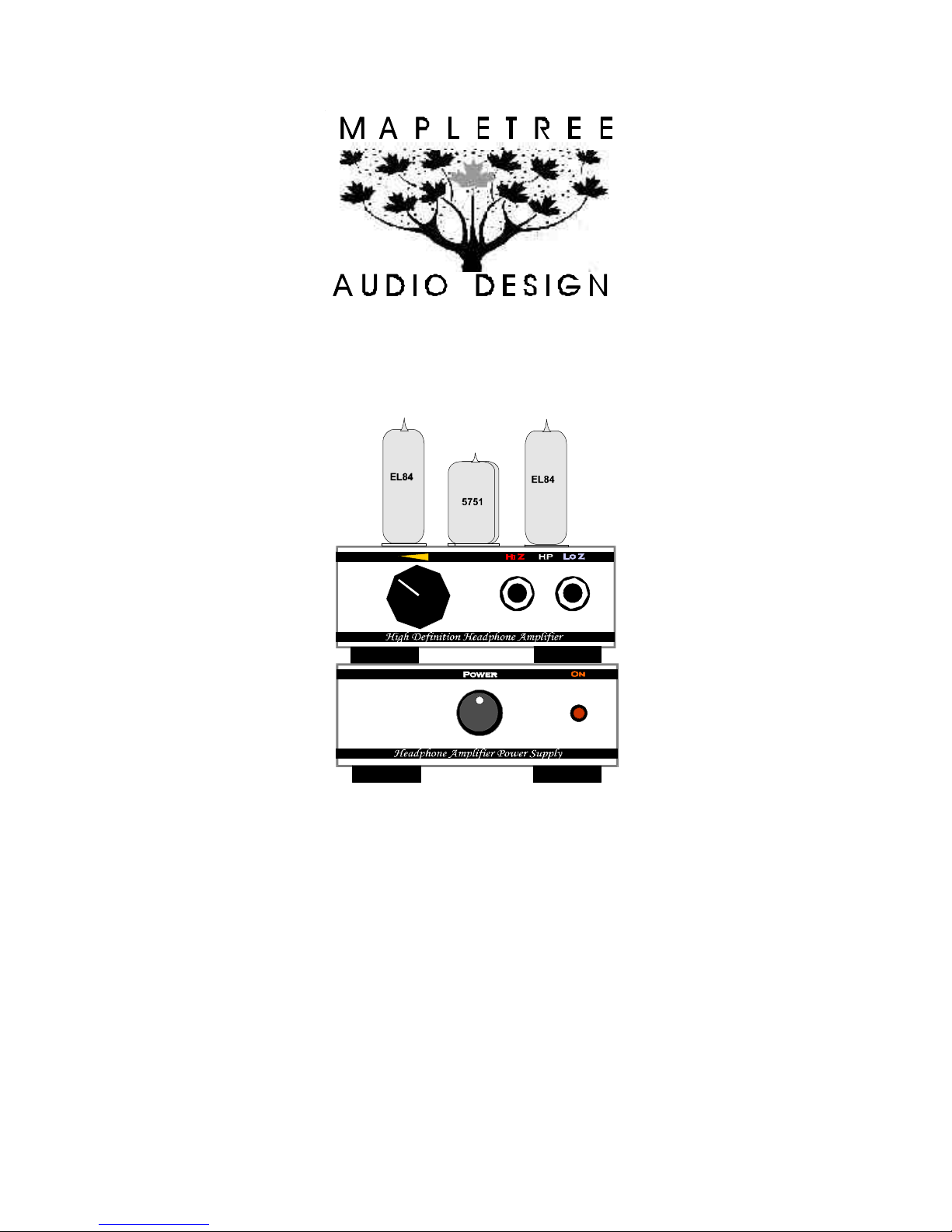
The Mapletree Audio Design Ear+ HD Super II Stereo Headphone Amplifier represents
a high performance development of the Ear+ family. The use of a high capacity power
supply provides increased power output and lower driving impedance employing widely
available EL84 output tubes and 12AX7/5751 drivers. The separate power supply chassis
allows flexibility in positioning each unit and reduces the heat seen by components in the
main amplifier chassis. Premium components include Tantalum film resistors in the
SRPP driver stage and an Alps volume control.
Input/Output Connections______
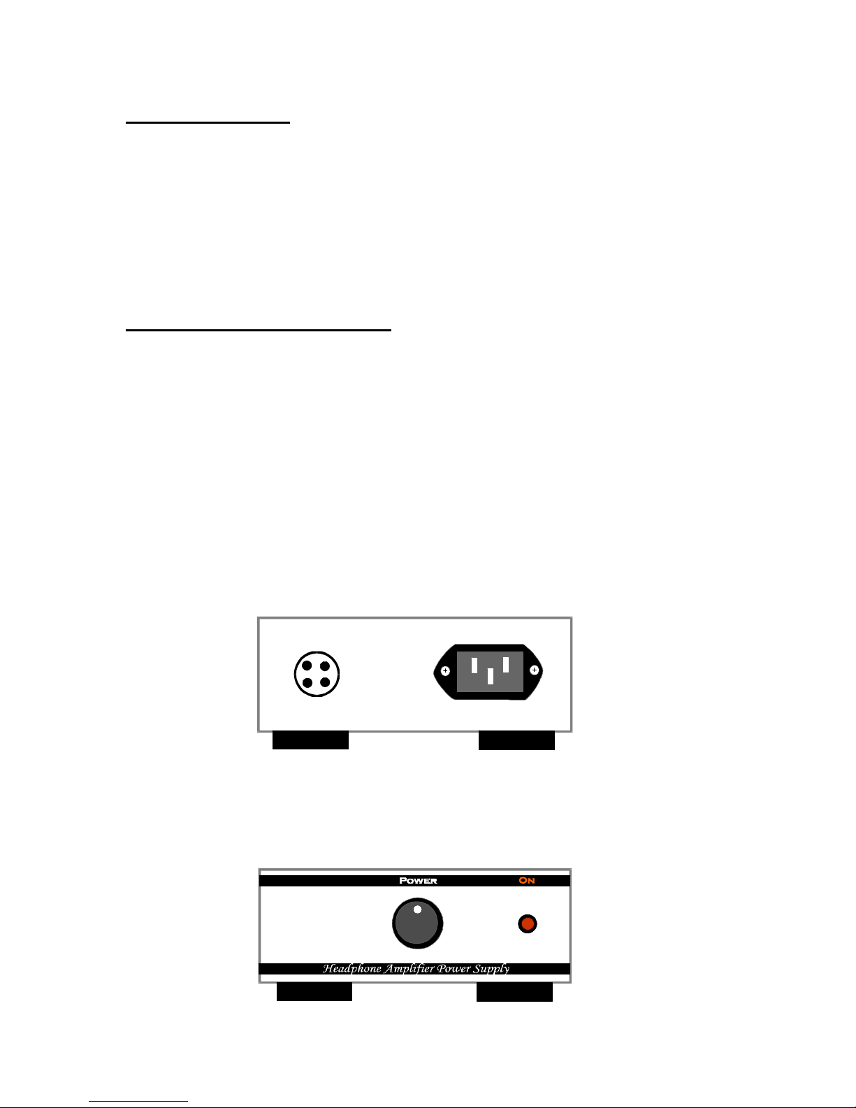
The standard IEC line cord is attached to the receptacle on the rear panel of the Ear+ HD
Super II power supply. It is compatible with a 115-125 VAC line with a frequency of 50–
60 Hz. The third pin is connected to the power supply chassis. A 1A/250 V fuse provides
primary protection for the power supply. It is located under the chassis and can be
accessed by removing the bottom cover of the power supply with the unit unplugged and
waiting 1 minute after powering off. Under normal conditions, it should not be necessary
to replace the fuse. If power fails to come on, you can check the fuse and replace with a
spare if necessary. If the fuse blows a second time, you should not try to operate the unit.
Contact Mapletree Audio Design for information regarding service.
The power supply is connected to the amplifier chassis with the supplied power
interconnect cord. Never power on the power supply without making this connection. The
two chassis may be stacked or separated as permitted by the power interconnect cord.
The power switch is located on the front panel of the power supply. The LED pilot light
indicates the power on condition. It is powered by the heater supply voltage so is an
indication that power is being supplied to the tube filaments. It takes about 30 seconds for
the tubes to reach operating temperature ready for use.
Page 3

3
The RCA input jacks (IN 1– IN 2) are wired in parallel to permit patching the source
EL84
signal to a preamp or integrated amp without the need for Y-adaptors. Left channel jacks
are at the top. The input impedance is 50 k? .
The headphone output jacks are standard ¼" stereo phones jacks with the left channel
connected to the tip contact. If your headphones are terminated in a 1/8" plug, an adaptor
is required (usually supplied with your headphones). Headphone impedances from 30 to
300 ? are suitable for use with either the high impedance (Hi Z) or low impedance (Lo
Z) output jacks. The low impedance output provides a slightly reduced gain for low
impedance phones such as the Grado Prestige series, which may be desirable depending
on your preferred listening levels. Any impedance headphones can be used in either jack
without sonic penalty. The enhanced power output of the HD Super II permits two sets of
headphones to be driven at the same time.
Tubes____
12AX7
(L)
(L)
12AX7
(R)
EL84
(R)
Page 4

4
Tube socket locations are shown above. When inserting tubes, take care to align the pins
before pushing firmly into the socket. Removal is easier if a slight rocking motion is used
at the same time as the tube is pulled from the socket.
A tube burn-in period of several hours may be needed to achieve the best sonic
performance. Tube life should be thousands of hours. Aging tubes may result in a
reduced gain in one or both channels or an increase in noise levels. Infrequently, a heater
may burn out which is indicated by total loss of sound. The Ear+ HD Super II is supplied
with 2 – 5751/12AX7 (driver), 2 – EL84/6BQ5 (output) tubes. Matched pairs are not
required. Replacement tubes can be obtained from several suppliers in the U. S. and
Canada. Both types are currently manufactured and are also available as new old stock
(NOS). Some listeners enjoy trying different brands and variants of tubes. The greatest
sonic variation will occur with different driver tubes. Any 12AX7 equivalent (e.g. 7025A
or ECC83) may be used as lo ng as the heater current does not exceed 0.3 A at 6.3 VAC.
Consult a substitution guide or tube manual.
Warranty___
Factory assembled MAD components are warranted for 2 years to the original purchaser for failure of all parts (excluding tubes).
Tubes are warranted for 90 days exclusive of shipping cost. Service, including parts and labor (but excluding shipping), is free within
the warranty period.
Page 5

5
MAD Ear+ HD Super II Specifications______
V
out
= 4 V rms
V
out
= 5 V rms
V
out
=
2 V rms
Frequency response at 1 V rms (20 mW) output into 50 Ohms:
5
0
-5
-10
-15
-20
10 100 1000 10000 100000
Frequency (Hz)
Maximum undistorted output at 1 kHz: 4 V rms with 50 Ohm load connected to Hi Z output (= 0.32 W).
P
o(max) Rload
680 mW 25 ?
500 mW 32 ?
160 mW 100 ?
57 mW 300 ?
28 mW 600 ?
Overload characteristic (1 kHz, 50 Ohm load, Hi Z output)
Output impedance at 1 kHz: Hi Z: < 2.6 ??, Lo Z: < 1.3 ??
Input impedance: 50 k? ?
Gain: Hi Z: 11 dB, Lo Z : 8 dB
Hum and noise at output (max volume, Hi Z): less than 0.4 mV rms (80 dB below max. output)
Recommended load impedance: 20–600 ?
Phase: non-inverting
Power consumption: 65 W, 120 VAC 50-60 Hz
Page 6

6
Mapletree Audio Design
Ear+ HD Super II Headphone Amplifier
© Copyright Lloyd Peppard 2010-13
Rev. Feb. 24/13
12AX7/5751
6
+235 V
IN L
Chassis
IN R
Volume
50K
Alps
Ground bus
50K
Ground bus
10K
1% MF
10K
1% MF
8
1K
1%
Tant
1
2
3
+1.12 V
1K
1%
Tant
12AX7/5751
6
8
1K
1%
Tant.
1
2
3
1K
1%
Tant
7
+120 V
EL84
7
2
3
3.9K
10W
WW
7
EL84
7
2
3
3.9K
10W
WW
+127 V
+307 V
200
9
+
33u/160V
200
9
+
33u/160V
Hammond 119DA
600:8
??
??
??
Hammond 119DA
600:8
??
??
??
Headphones
Hi Z
Headphones
Lo Z
Chassis
1 A/250 V
L
N
120 VAC
EL84
33K
1 W 5% CF
100u/400V
+6.4 V
4
9
5
12AX7
+235 V
+
4
9
5
12AX7
Power
120VAC
110mA
120VAC
110mA
28VAC
110mA
28VAC
110mA
6.3 VAC
3.2 A
MUR180
6 A
10000u/25V
100u/400V
+
Power Supply
1K/10W
+370 V
+ +
100u/400V
4
3
Power out
LED
Pilot
1K
1
2
220K
2W
Power in
4
3
2
+307 V
1
4
4
5
5
EL84
 Loading...