

Page 1

Your Industrial Control Solutions Source
_____________________
www.maplesystems.com
Maple Systems, Inc. | 808 134th St. SW, Suite 120, Everett, WA 98204 | 425.745.3229
OMI Operations Manual
OMI6800 Light Industrial Panel PC Series
For use with the following:
OMI6800 Series
Page 2

OMI Operations Manual: OMI6800 Series 2
TABLE OF CONTENTS
COPYRIGHT NOTICE .................................................................................................... 4
WARRANTY ................................................................................................................... 4
TECHNICAL SUPPORT ................................................................................................. 4
UNPACKING THE UNIT ................................................................................................. 4
SAFETY PRECAUTIONS ............................................................................................... 5
DIMENSIONS AND SPECIFICATIONS .......................................................................... 6
OMI6807A DIMENSIONS ........................................................................................... 6
OMI6807A SPECIFICATIONS .................................................................................... 7
OMI6808A DIMENSIONS ........................................................................................... 8
OMI6808A SPECIFICATIONS .................................................................................... 9
OMI6810A DIMENSIONS ......................................................................................... 10
OMI6810A SPECIFICATIONS .................................................................................. 11
OMI6812A DIMENSIONS ......................................................................................... 12
OMI6812A SPECIFICATIONS .................................................................................. 13
OMI6815A DIMENSIONS ......................................................................................... 14
OMI6815A SPECIFICATIONS .................................................................................. 15
OMI6816A SPECIFICATIONS .................................................................................. 17
OMI6818A DIMENSIONS ......................................................................................... 18
OMI6818A SPECIFICATIONS .................................................................................. 19
OMI6821A DIMENSIONS ......................................................................................... 20
OVERVIEW OF OMI6800 SERIES ............................................................................... 22
Front View of OMI6800 Series .................................................................................. 22
Rear View of OMI6807 .............................................................................................. 23
Rear View of OMI6808 .............................................................................................. 23
Rear View of OMI6810 .............................................................................................. 24
Rear View of OMI6812 .............................................................................................. 24
Rear View of OMI6815 .............................................................................................. 25
Rear View of OMI6816 .............................................................................................. 25
Rear View of OMI6818 .............................................................................................. 26
Rear View of OMI6821 .............................................................................................. 26
I/O PORTS .................................................................................................................... 27
COM1 AND COM2: ................................................................................................... 27
LINE OUT: ................................................................................................................. 27
USB: .......................................................................................................................... 28
LAN1 and LAN2: ....................................................................................................... 28
SETTING COM1 FUNCTION ........................................................................................ 29
SD CARD INSTALLATION ........................................................................................... 31
REMOTE POWER SWITCH CONFIGURATION .......................................................... 32
VESA MOUNTING ........................................................................................................ 33
PANEL MOUNTING ...................................................................................................... 33
OMI Operations Manual: OMI6800 Series 2
Page 3

OMI Operations Manual: OMI6800 Series 3
INSTALLATION OF DRIVERS ..................................................................................... 34
DRIVER INSTALLATION FOR WINDOWS 7 ........................................................... 34
Intel Chipset Driver ................................................................................................. 34
VGA Driver ............................................................................................................. 36
LAN Driver .............................................................................................................. 39
Audio Driver ............................................................................................................ 40
USB 3.0 Driver ........................................................................................................ 41
Touch Screen Driver ............................................................................................... 43
COM Driver............................................................................................................. 44
DRIVERS INSTALLATION FOR WINDOWS 10 ...................................................... 46
Video Driver: ........................................................................................................... 46
Intel TXE (Win) Driver ............................................................................................. 48
Audio Driver ............................................................................................................ 49
Chipset Driver ......................................................................................................... 50
Touch Screen ......................................................................................................... 51
TOUCH SCREEN CALIBRATION ................................................................................ 51
Touch Screen Settings .............................................................................................. 53
Touch Screen Edge Compensation .......................................................................... 55
OPERATING SYSTEM OPTIONS ................................................................................ 55
Windows Embedded Standard 7 ............................................................................... 55
Windows 7 Professional for Embedded Systems ...................................................... 55
Windows 10 IoT Enterprise 2016 LTSB .................................................................... 55
WONDERWARE / INDUSOFT WEBSTUDIO ............................................................... 56
OMI Operations Manual: OMI6800 Series 3
Page 4

OMI Operations Manual: OMI6800 Series 4
Packing List
OMI6800 Series Light Industrial Panel PC
DC Power Connector (3 pin terminal block)
DC Power adapter with cord
Mounting Clamp Kit
Support CD
Windows Recovery CD (for non-embedded operating systems only)
COPYRIGHT NOTICE
This manual is a publication of Maple Systems, Inc., and is provided for use by its customers only. The
contents of the manual are copyrighted by Maple Systems, Inc.; reproduction in whole or in part, for use
other than in support of Maple Systems equipment, is prohibited without the specific written permission of
Maple Systems.
WARRANTY
Warranty Statements are included with each unit at the time of purchase and are available at
www.maplesystems.com.
TECHNICAL SUPPORT
This manual is designed to provide the necessary information for trouble-free installation and operation of
your new OMI. However, if you need assistance, please contact Maple Systems:
Phone: 425-745-3229
Email: support@maplesystems.com
Web: http://www.maplesystems.com
UNPACKING THE UNIT
Carefully unpack the OMI6800. Check all material in the container against the packing list. Maple
Systems will not accept responsibility for shortages against the packing list unless notified within 30 days.
The equipment and accessories were inspected and tested by Maple Systems before shipment.
Examine the equipment carefully; if any shipping damage is evident, notify the carrier immediately. Maple
Systems is not responsible for claim negotiations with the carrier.
Save the shipping container and packing material in case the equipment needs to be stored, returned to
Maple Systems, or transported for any reason.
OMI Operations Manual: OMI6800 Series 4
Page 5
OMI Operations Manual: OMI6800 Series 5
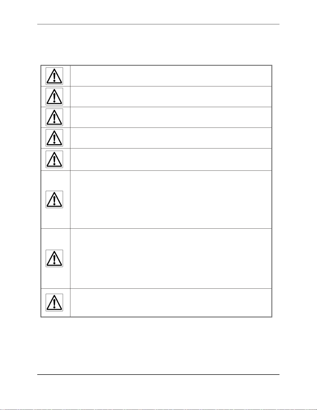
Warning: Disconnect this equipment from any power before cleaning. Do not
use liquid or spray detergents for cleaning. Use a damp cloth.
Warning: Keep this equipment away from humidity.
Warning: Before applying power the unit make sure the voltage of the power
source is within the input voltage rating of the unit.
Warning: Position the power cord so that people cannot step on it. Do not place
anything over the power cord.
Warning: Never open the equipment and do not operate equipment with its back
cover removed- there are dangerous high voltages present inside. For safety
reasons, the equipment should be opened only by a qualified service technician.
Warning: This equipment generates, uses and can radiate radio frequency
energy and if not installed and used in accordance with the instructions manual, it
may cause interference to radio communications. It has been tested and found to
comply with the limits for a Class A computing device pursuant to FCC Rules,
which are designed to provide reasonable protection against such interference
when operated in a commercial environment. Operation of this equipment in a
residential area is likely to cause interference in which case the user at his own
expense will be required to take whatever measures may be required to correct the
interference.
Warning: If any of the following situations arise, get the equipment checked by
qualified service personnel.
The power cord or plug is damaged.
Liquid has penetrated into the equipment.
The equipment has been exposed to moisture.
The equipment does not work well, or you cannot get it to work according to this
operations manual.
The equipment has been dropped and damaged.
The equipment has obvious signs of breakage.
Warning: Do not leave this equipment in an uncontrolled environment where the
storage temperature is below -20°C (-4°F) or above 60°C (140°F). It may damage
the equipment.
SAFETY PRECAUTIONS
Please observe the following precautions when installing the OMI6800 Series Open HMIs. Failure to
comply with these restrictions could result in loss of life, serious personal injury, or equipment damage.
OMI Operations Manual: OMI6800 Series 5
Page 6
OMI Operations Manual: OMI6800 Series 6
Top View
Front View
Bottom View
Rear View
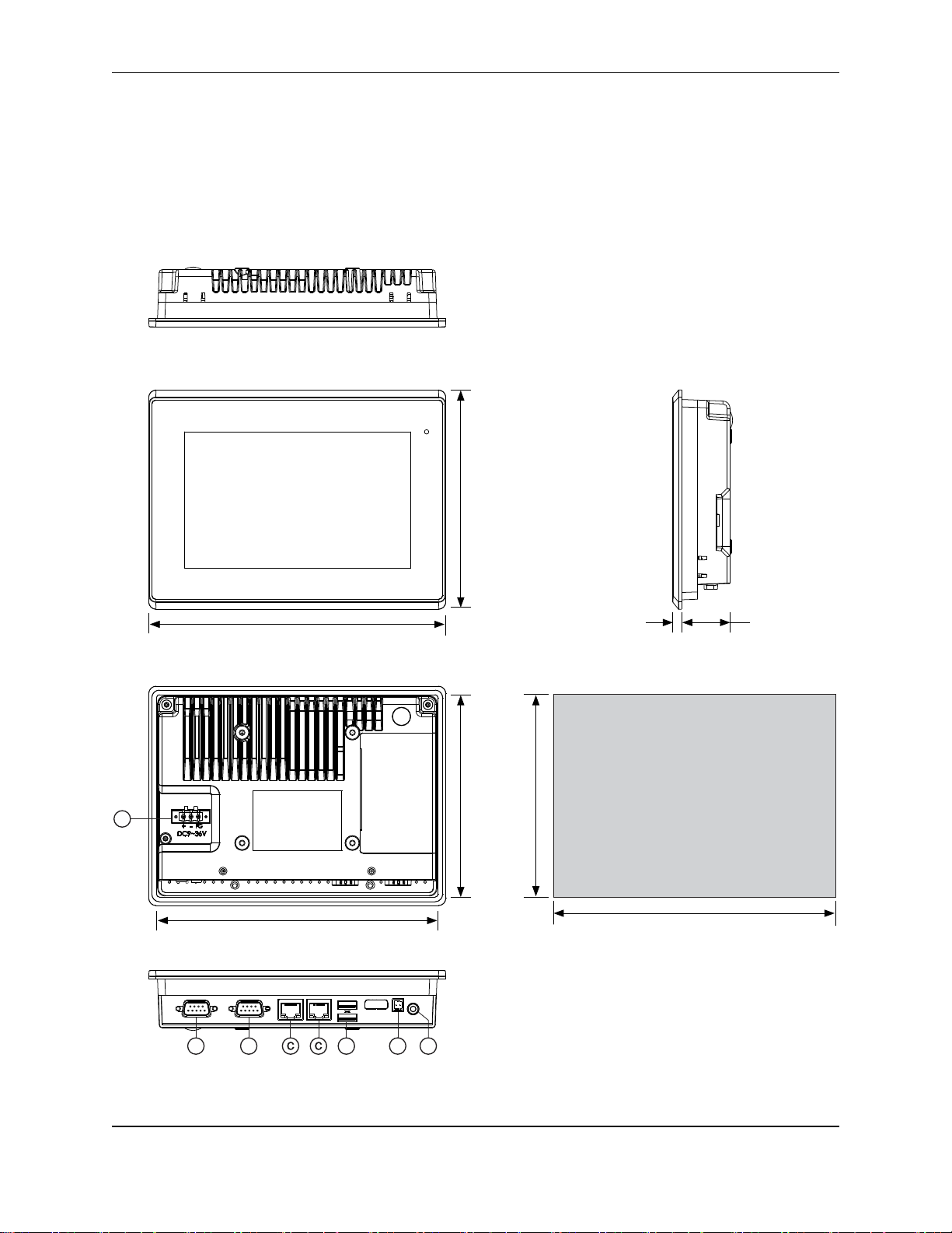
5.43
[138.0]
7.56
[192.0]
Side View
7.48
[190.0]
5.35
[136.0]
5.87
[149.0]
7.95”
[202.0]
IMPORTANT
Dimensions shown are
estimates, and may not work
with your mounting scheme. We
recommend measuring your
actual cutout dimensions for a
proper fit.
0.24
[6.0]
1.30
[33.0]
Cutout Dimensions
A
BB D F
Dimensions are in inches [mm]
E
DIMENSIONS AND SPECIFICATIONS
The following section contains the Dimensions and Specifications for the OMI6800 series Light Industrial
Panel PCs.
OMI6807A DIMENSIONS
OMI Operations Manual: OMI6800 Series 6
Page 7

OMI Operations Manual: OMI6800 Series 7
System
CPU
Intel Celeron N2930 1.83 GHz Quad-Core processor
System Chipset
SoC
System Memory
Onboard DDR3L 4 GB 1600 MHz
I/O Ports
USB
2 x USB 3.0 type A
Serial
COM1: RS-232/422/485 DE-9P (default RS-232)
COM2: RS-232 DE-9P
Audio
1 x 3.5 mm line out
LAN
2 x GbE RJ-45
Power
3-pin connector header, DC power input
Remote Power Switch
2-pin connector header
Storage
Solid State Drive
Options*
32 GB SSD, 1 x 1.8” SATA 2, MLC
64 GB SSD, 1 x 1.8” SATA 2, MLC
128 GB SSD, 1 x 1.8” SATA 2, MLC
256 GB SSD, 1 x 1.8” SATA 2, MLC
SD Card Slot
1 x internal Secure Digital memory card socket, up to 32 GB
Expansion
Expansion Slot
Optional Wi-Fi kit (Wi-Fi card and antenna)
Display
Display Type
7” TFT-LCD
Max. Resolution
800 x 480
Max. Color
262K
Luminance (cd/m²)
350
View Angle (H°/V°)
140/110
Contrast Ratio
400:1
Backlight Lifetime
(hours)
40,000+
Touch Screen
Type
5-wire resistive touch
Interface
USB
Light Transmission
80%
Electrical
Input Voltage
9~36 VDC
Input Current
0.6 ~ 2.6 A
Input Power
14.1 W
Mechanical
Construction
Silver aluminum front bezel and chassis
Rating
IP66 front panel / NEMA4X
Mounting
Panel mounting, VESA 75 x 75
Dimension (W x H x D)
7.95 x 5.87 x 1.54 inches [202 x 149 x 39 mm]
Net Weight
2.52 lbs [1.14 kg]
Environmental
Operating Temperature
32~122°F [0~50°C]
Storage Temperature
-4~140°F [-20~60°C]
Storage Humidity
10 to 90% @ 40°C, non-condensing
Certification
CE / FCC Class A / cULus / RoHS
Operating
System
Microsoft Windows
Options **
Microsoft Windows© Embedded Standard 7 32-bit or 64-bit (WS7P)
Microsoft Windows© 7 Pro for Embedded 32-bit or 64-bit (FES 7 Pro)
Microsoft Windows© 10 IoT Enterprise Embedded 2016 32-bit or 64-bit
(EPKEA)
Microsoft WIndows© 10 IoT Enterprise 2016 LTSB 32-bit or 64-bit (PKEA)
Notes
Specifications subject to change without notice.
* Additional SSD options available; contact Maple Systems for details.
** 32-bit or 64-bit must be specified at the time the order is placed.
OMI6807A SPECIFICATIONS
OMI Operations Manual: OMI6800 Series 7
Page 8
OMI Operations Manual: OMI6800 Series 8
A
Power Connector
B
Com Port DE9P Ethernet Port
D
USB 3.0 Ports
E
SW Connector
F
Line out
Top View
Front View
Bottom View
Rear View
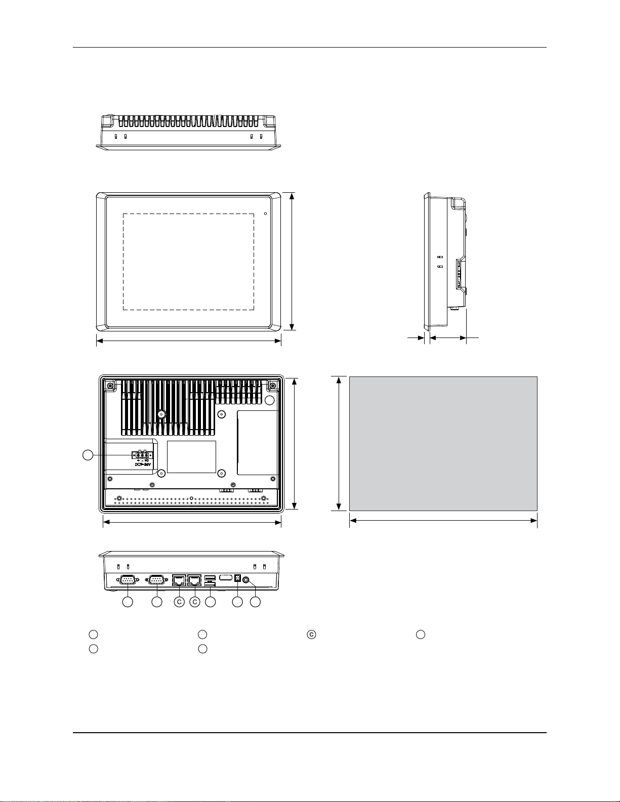
6.58
[167.0]
8.74
[222.0]
Side View
8.66
[220.0]
6.50
[165.0]
6.94
[176.1]
9.10”
[231.1]
IMPORTANT
Dimensions shown are
estimates, and may not work
with your mounting scheme. We
recommend measuring your
actual cutout dimensions for a
proper fit.
0.28
[7.0]
1.70
[43.0]
Cutout Dimensions
A
BB D F
Dimensions are in inches [mm]
E
USB LAN 1 COM 2COM 1LAN 2+ -Line-Out
OMI6808A DIMENSIONS
OMI Operations Manual: OMI6800 Series 8
Page 9

OMI Operations Manual: OMI6800 Series 9
System
CPU
Intel Celeron N2930 1.83 GHz Quad-Core processor
System Chipset
SoC
System Memory
Onboard DDR3L 4 GB 1600 MHz
I/O Ports
USB
2 x USB 3.0 type A
Serial
COM1: RS-232/422/485 DE-9P (default RS-232)
COM2: RS-232 DE-9P
Audio
1 x 3.5 mm line out
LAN
2 x GbE RJ-45
Power
3-pin connector header, DC power input
Remote Power Switch
2-pin connector header
Storage
Solid State Drive
Options *
32 GB SSD, 1 x 1.8” SATA 2, MLC
64 GB SSD, 1 x 1.8” SATA 2, MLC
128 GB SSD, 1 x 1.8” SATA 2, MLC
256 GB SSD, 1 x 1.8” SATA 2, MLC
SD Card Slot
1 x internal Secure Digital memory card socket, up to 32 GB
Expansion
Expansion Slot
Optional Wi-Fi kit (Wi-Fi card and antenna)
Display
Display Type
8” TFT-LCD
Max. Resolution
800 x 600
Max. Color
16.2 M
Luminance (cd/m²)
350
View Angle (H°/V°)
140/125
Contrast Ratio
500:1
Backlight Lifetime
(hours)
40,000+
Touch Screen
Type
5-wire resistive touch
Interface
USB
Light Transmission
80%
Electrical
Input Voltage
9~36 VDC
Input Current
0.3 ~ 1.2 A
Input Power
10.8 W
Mechanical
Construction
Silver aluminum front bezel and chassis
Rating
IP66 front panel / NEMA4X
Mounting
Panel mounting, VESA 75 x 75
Dimension (W x H x D)
9.09 x 6.93 x 1.97 inches [231 x 176 x 50 mm]
Net Weight
4.19 lbs [1.9 kg]
Environmental
Operating Temperature
32~122°F [0~50°C]
Storage Temperature
-4~140°F [-20~60°C]
Storage Humidity
10 to 90% @ 40°C, non-condensing
Certification
CE / FCC Class A / cULus / RoHS
Operating
System
Microsoft Windows
Options **
Microsoft Windows© Embedded Standard 7 32-bit or 64-bit (WS7P)
Microsoft Windows© 7 Pro for Embedded 32-bit or 64-bit (FES 7 Pro)
Microsoft Windows© 10 IoT Enterprise Embedded 2016 LTSB 32-bit or 64bit (EPKEA)
Microsoft Windows© 10 IoT Enterprise 2016 LTSB 32-bit or 64-bit (PKEA)
Notes
Specifications subject to change without notice.
* Additional SSD options available; contact Maple Systems for details.
**32-bit or 64-bit must be specified at the time the order is placed.
OMI6808A SPECIFICATIONS
OMI Operations Manual: OMI6800 Series 9
Page 10
OMI Operations Manual: OMI6800 Series 10
Top View
Front View
Bottom View
Rear View
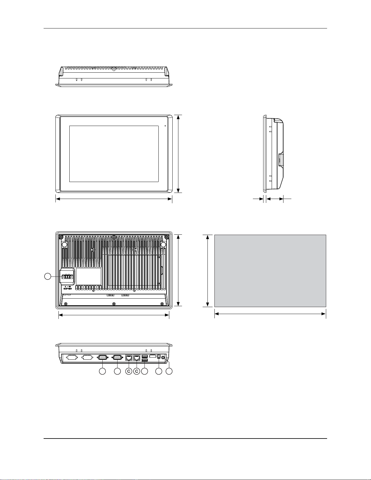
6.93
[176.0]
10.71
[272.0]
Side View
10.63
[270.0]
6.85
[174.0]
7.44
[189.0]
11.22
[285.0]
IMPORTANT
Dimensions shown are
estimates, and may not work
with your mounting scheme. We
recommend measuring your
actual cutout dimensions for a
proper fit.
0.28
[7.0]
1.65
[41.9]
Cutout Dimensions
A
BB D E
Dimensions are in inches [mm]
F
OMI6810A DIMENSIONS
OMI Operations Manual: OMI6800 Series 10
Page 11

OMI Operations Manual: OMI6800 Series 11
System
CPU
Intel Celeron N2930 1.83 GHz Quad-Core processor
System Chipset
SoC
System Memory
Onboard DDR3L 4 GB 1600 MHz
I/O Ports
USB
2 x USB 3.0 type A
Serial
COM1: RS-232/422/485 DE-9P (default RS-232)
COM2: RS-232 DE-9P
Audio
1 x 3.5 mm line out
LAN
2 x GbE RJ-45
Power
3-pin connector header, DC power input
Remote Power Switch
2-pin connector header
Storage
Solid State Drive
Options *
32 GB SSD, 1 x 2.5” SATA 2, MLC
64 GB SSD, 1 x 2.5” SATA 2, MLC
128 GB SSD, 1 x 2.5” SATA 2, MLC
256 GB SSD, 1 x 2.5” SATA 2, MLC
SD Card Slot
1 x internal Secure Digital memory card socket, up to 32 GB
Expansion
Expansion Slot
Optional Wi-Fi kit (Wi-Fi card and antenna)
Display
Display Type
10.1” TFT-LCD
Max. Resolution
1280 x 800
Max. Color
16.7M
Luminance (cd/m²)
350
View Angle (H°/V°)
160/160
Contrast Ratio
800:1
Backlight Lifetime
(hours)
50,000+
Touch Screen
Type
5-wire resistive touch
Interface
USB
Light Transmission
80%
Electrical
Input Voltage
9~36 VDC
Input Current
0.3 ~ 1.2 A
Input Power
11.2 W
Mechanical
Construction
Silver aluminum front bezel and chassis
Rating
IP66 front panel / NEMA4X
Mounting
Panel mounting, VESA 100 x 100
Dimension (W x H x D)
11.22 x 7.44 x 1.93 inches [285 x 189 x 48.9 mm]
Net Weight
4.19 lbs [1.9 kg]
Environmental
Operating Temperature
32~122°F [0~50°C]
Storage Temperature
-4~140°F [-20~60°C]
Storage Humidity
10 to 90% @ 40°C, non-condensing
Certification
CE / FCC Class A / cULus / RoHS
Operating
System
Microsoft Windows
Options **
Microsoft Windows© Embedded Standard 7 32-bit or 64-bit (WS7P)
Microsoft Windows© 7 Pro for Embedded 32-bit or 64-bit (FES 7 Pro)
Microsoft Windows© 10 IoT Enterprise Embedded 2016 32-bit or 64-bit
(EPKEA)
Microsoft Windows© 10 IoT Enterprise 2016 LTSB 32-bit or 64-bit (PKEA)
Notes
Specifications subject to change without notice.
* Additional SSD options available; contact Maple Systems for details.
** 32-bit or 64-bit must be specified at the time the order is placed.
OMI6810A SPECIFICATIONS
OMI Operations Manual: OMI6800 Series 11
Page 12
OMI Operations Manual: OMI6800 Series 12
Top View
Front View
Bottom View
Rear View
9.02
[229.0]
11.93
[303.0]
Side View
11.85
[301.0]
8.94
[227.0]
9.65
[245.0]
12.56
[319.0]
IMPORTANT
Dimensions shown are
estimates, and may not work
with your mounting scheme. We
recommend measuring your
actual cutout dimensions for a
proper fit.
0.33
[8.4]
1.70
[43.3]
Cutout Dimensions
BB D F
LAN 2 CO M 1 CO M 2LAN 1USB
A
Dimensions are in inches [mm]
Line-Out
SW
+
E
OMI6812A DIMENSIONS
OMI Operations Manual: OMI6800 Series 12
Page 13

OMI Operations Manual: OMI6800 Series 13
System
CPU
Intel Celeron N2930 1.83 GHz Quad-Core processor
System Chipset
SoC
System Memory
Onboard DDR3L 4 GB 1600 MHz
I/O Ports
USB
2 x USB 3.0 type A
Serial
COM1: RS-232/422/485 DE-9P (default RS-232)
COM2: RS-232 DE-9P
Audio
1 x 3.5 mm line out
LAN
2 x GbE RJ-45
Power
3-pin connector header, DC power input
Remote Power Switch
2-pin connector header
Storage Space
Solid State Drive
Options *
32 GB SSD, 1 x 2.5” SATA 2, MLC
64 GB SSD, 1 x 2.5” SATA 2, MLC
128 GB SSD, 1 x 2.5” SATA 2, MLC
256 GB SSD, 1 x 2.5” SATA 2, MLC
SD Card Slot
1 x internal Secure Digital memory card socket, up to 32 GB
Expansion
Expansion Slot
Optional Wi-Fi kit (Wi-Fi card and antenna)
Display
Display Type
12.1” TFT-LCD
Max. Resolution
800 x 600
Max. Color
16.2M
Luminance (cd/m²)
330
View Angle (H°/V°)
160/140
Contrast Ratio
800:1
Backlight Lifetime
(hours)
50,000+
Touch Screen
Type
5-wire resistive touch
Interface
USB
Light Transmission
80%
Electrical
Input Voltage
9~36 VDC
Input Current
0.5 ~ 2.2 A
Input Power
19.5 W
Mechanical
Construction
Silver aluminum front bezel and chassis
Rating
IP66 front panel / NEMA4X
Mounting
Panel mounting, VESA 100 x 100
Dimension
12.56 x 9.65 x 2.03 inches [319 x 245 x 51.7 mm]
Net Weight
6.2 lbs [2.8 kg]
Environmental
Operating Temperature
32~122°F [0~50°C]
Storage Temperature
-4~140°F [-20~60°C]
Storage Humidity
10 to 90% @ 40°C, non-condensing
Certification
CE / FCC Class A / cULus / RoHS
Operating
System
Microsoft Windows
Options **
Microsoft Windows© Embedded Standard 7 32-bit or 64-bit (WS7P)
Microsoft Windows© 7 Pro for Embedded 32-bit or 64-bit (FES 7 Pro)
Microsoft Windows© 10 IoT Enterprise Embedded 2016 32-bit or 64-bit
(EPKEA)
Microsoft Windows© 10 IoT Enterprise 2016 LTSB 32-bit or 64-bit (PKEA)
Notes
Specifications subject to change without notice.
* Additional SSD options available; contact Maple Systems for details.
** 32-bit or 64-bit must be specified at the time the order is placed.
OMI6812A SPECIFICATIONS
OMI Operations Manual: OMI6800 Series 13
Page 14
OMI Operations Manual: OMI6800 Series 14
Top View
Front View
Bottom View
Rear View
11.50
[292.0]
15.43
[392.0]
Side View
15.36
[390.0]
12.20
[310.0]
16.14
[410.0]
IMPORTANT
Dimensions shown are
estimates, and may not work
with your mounting scheme. We
recommend measuring your
actual cutout dimensions for a
proper fit.
0.33
[8.4]
Cutout Dimensions
LAN 2
CO M 1 CO M 2
LAN 1
USB
B D EB
A
Line-Out
SW
+
F
Dimensions are in inches [mm]
11.42
[290.0]
1.82
[46.3]
OMI6815A DIMENSIONS
OMI Operations Manual: OMI6800 Series 14
Page 15

OMI Operations Manual: OMI6800 Series 15
System
CPU
Intel Celeron N2930 1.83 GHz Quad-Core processor
System Chipset
SoC
System Memory
Onboard DDR3L 4 GB 1600 MHz
I/O Ports
USB
2 x USB 3.0 type A
Serial
COM1: RS-232/422/485 DE-9P (default RS-232)
COM2: RS-232 DE-9P
Audio
1 x 3.5 mm line out
LAN
2 x GbE RJ-45
Power
3-pin connector header, DC power input
Remote Power Switch
2-pin connector header
Storage
Solid State Drive
Options *
32 GB SSD, 1 x 2.5” SATA 2, MLC
64 GB SSD, 1 x 2.5” SATA 2, MLC
128 GB SSD, 1 x 2.5” SATA 2, MLC
256 GB SSD, 1 x 2.5” SATA 2, MLC
SD Card Slot
1 x internal Secure Digital memory card socket, up to 32 GB
Expansion
Expansion Slot
Optional Wi-Fi kit (Wi-Fi card and antenna)
Display
Display Type
15.1” TFT-LCD
Max. Resolution
1024 x 768
Max. Color
16.7 M
Luminance (cd/m²)
450
View Angle (H°/V°)
160/140
Contrast Ratio
800:1
Backlight Lifetime
(hours)
60,000+
Touch Screen
Type
5-wire resistive touch
Interface
USB
Light Transmission
80%
Electrical
Input Voltage
9~36 VDC
Input Current
0.5 ~ 2 A
Input Power
17.8 W
Mechanical
Construction
Silver aluminum front bezel and chassis
Rating
IP66 front panel / NEMA4X
Mounting
Panel mounting, VESA 100 x 100
Dimension (W x H x D)
16.14 x 12.20 x 2.15 inches [410 x 310 x 54.67 mm]
Net Weight
9.7 lbs [4.4 kg]
Environmental
Operating Temperature
32~122°F [0~50°C]
Storage Temperature
-4~140°F [-20~60°C]
Storage Humidity
10 to 90% @ 40°C, non-condensing
Certification
CE / FCC Class A / cULus / RoHS
Operating
System
Microsoft Windows
Options **
Microsoft Windows© Embedded Standard 7 32-bit or 64-bit (WS7P)
Microsoft Windows© 7 Pro for Embedded 32-bit or 64-bit (FES 7 Pro)
Microsoft Windows© 10 IoT Enterprise Embedded 2016 32-bit or 64-bit
(EPKEA)
Microsoft Windows© 10 IoT Enterprise 2016 LTSB 32-bit or 64-bit (PKEA)
Notes
Specifications subject to change without notice.
* Additional SSD options available; contact Maple Systems for details.
** 32-bit or 64-bit must be specified at the time the order is placed.
OMI6815A SPECIFICATIONS
OMI Operations Manual: OMI6800 Series 15
Page 16

OMI Operations Manual: OMI6800 Series 16
Top View
Front View
Bottom View
Rear View
10.22
[259.5]
15.51
[394.0]
Side View
15.43
[392.0]
10.14
[257.5]
10.93
[277.5]
16.22
[412.0]
IMPORTANT
Dimensions shown are
estimates, and may not work
with your mounting scheme. We
recommend measuring your
actual cutout dimensions for a
proper fit.
0.32
[8.0]
2.00
[50.9]
Cutout Dimensions
A
B D E
LAN 2 COM 1 COM 2LAN 1USBLine-OutSW
+
F
Dimensions are in inches [mm]
OMI6816A DIMENSIONS
OMI Operations Manual: OMI6800 Series 16
Page 17

OMI Operations Manual: OMI6800 Series 17
System
CPU
Intel Celeron N2930 1.83 GHz Quad-Core processor
System Chipset
SoC
System Memory
Onboard DDR3L 4 GB 1600 MHz
I/O Ports
USB
2 x USB 3.0 type A
Serial
COM1: RS-232/422/485 DE-9P (default RS-232)
COM2: RS-232 DE-9P
Audio
1 x 3.5 mm line out
LAN
2 x GbE RJ-45
Power
3-pin connector header, DC power input
Remote Power Switch
2-pin connector header
Storage
Solid State Drive
Options *
32 GB SSD, 1 x 2.5” SATA 2, MLC
64 GB SSD, 1 x 2.5” SATA 2, MLC
128 GB SSD, 1 x 2.5” SATA 2, MLC
256 GB SSD, 1 x 2.5” SATA 2, MLC
SD Card Slot
1 x internal Secure Digital memory card socket, up to 32 GB
Expansion
Expansion Slot
Optional Wi-Fi kit (Wi-Fi card and antenna)
Display
Display Type
15.6” TFT-LCD
Max. Resolution
1366 x 768
Max. Color
16.7 M
Luminance (cd/m²)
300
View Angle (H°/V°)
160/160
Contrast Ratio
500:1
Backlight Lifetime
(hours)
50,000+
Touch Screen
Type
5-wire resistive touch
Interface
USB
Light Transmission
80%
Electrical
Input Voltage
9~36 VDC
Input Current
0.6 ~ 2.2 A
Input Power
21.6 W
Mechanical
Construction
Silver aluminum front bezel and chassis
Rating
IP66 front panel / NEMA4X
Mounting
Panel mounting, VESA 100 x 100
Dimension (W x H x D)
16.23 x 10.93 x 2.37 inches [412 x 277.5 x 60.4 mm]
Net Weight
10.58 lbs [4.8 kg]
Environmental
Operating Temperature
32~122°F [0~50°C]
Storage Temperature
-4~140°F [-20~60°C]
Storage Humidity
10 to 90% @ 40°C, non-condensing
Certification
CE / FCC Class A / cULus / RoHS
Operating
System
Microsoft Windows
Options **
Microsoft Windows© Embedded Standard 7 32-bit or 64-bit (WS7P)
Microsoft Windows© 7 Pro for Embedded 32-bit or 64-bit (FES 7 Pro)
Microsoft Windows© 10 IoT Enterprise Embedded 2016 32-bit or 64-bit
(EPKEA)
Microsoft Windows© 10 IoT Enterprise 2016 LTSB 32-bit or 64-bit (PKEA)
Notes
Specifications subject to change without notice.
* Additional SSD options available; contact Maple Systems for details.
** 32-bit or 64-bit must be specified at the time the order is placed.
OMI6816A SPECIFICATIONS
OMI Operations Manual: OMI6800 Series 17
Page 18
OMI Operations Manual: OMI6800 Series 18
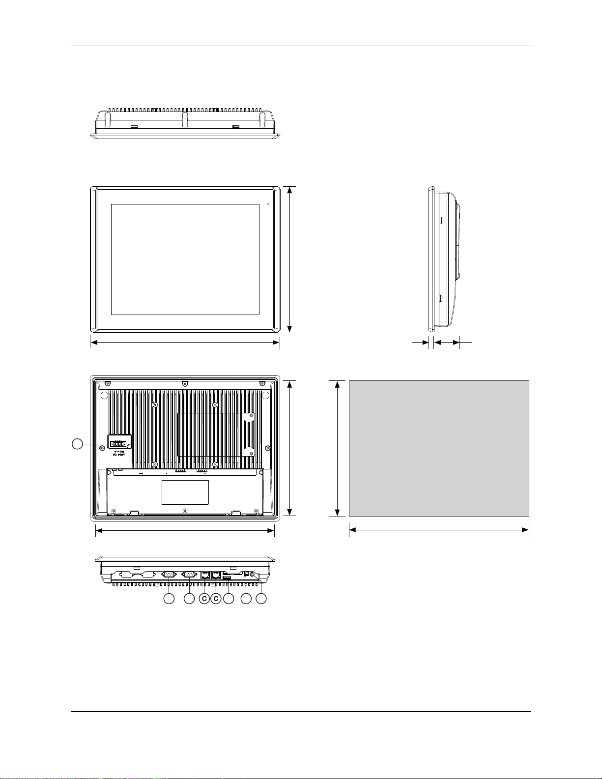
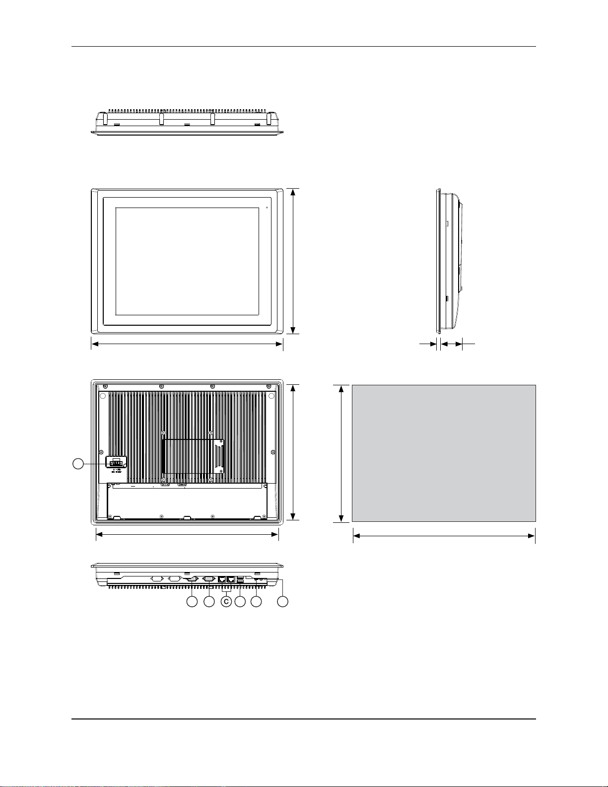
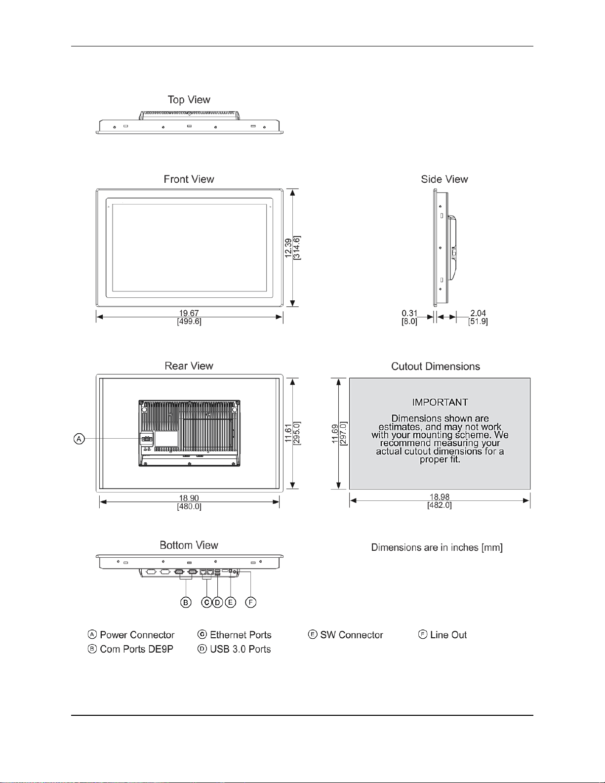
OMI6818A DIMENSIONS
OMI Operations Manual: OMI6800 Series 18
Page 19

OMI Operations Manual: OMI6800 Series 19
System
CPU
Intel Celeron N2930 1.83 GHz Quad-Core processor
System Chipset
SoC
System Memory
Onboard DDR3L 4 GB 1600 MHz
I/O Ports
USB
2 x USB 3.0 type A
Serial
COM1: RS-232/422/485 DE-9P (default RS-232)
COM2: RS-232 DE-9P
Audio
1 x 3.5 mm line out
LAN
2 x GbE RJ-45
Power
3-pin connector header, DC power input
Remote Power Switch
2-pin connector header
Storage
Solid State Drive
Options *
32 GB SSD, 1 x 2.5” SATA 2, MLC
64 GB SSD, 1 x 2.5” SATA 2, MLC
128 GB SSD, 1 x 2.5” SATA 2, MLC
256 GB SSD, 1 x 2.5” SATA 2, MLC
SD Card Slot
1 x internal Secure Digital memory card socket, up to 32 GB
Expansion
Expansion Slot
Optional Wi-Fi kit (Wi-Fi card and antenna)
Display
Display Type
18.5” TFT-LCD
Max. Resolution
1366 x 768
Max. Color
16.7 M
Luminance (cd/m²)
300
View Angle (H°/V°)
170/160
Contrast Ratio
1000:1
Backlight Lifetime
(hours)
50,000+
Touch Screen
Type
5-wire resistive touch
Interface
USB
Light Transmission
80%
Electrical
Input Voltage
9~36 VDC
Input Current
0.8 ~ 3.3 A
Input Power
29.8 W
Mechanical
Construction
Silver aluminum front bezel and chassis
Rating
IP66 front panel / NEMA4X
Mounting
Panel mounting, VESA 100 x 100
Dimension (W x H x D)
19.67 x 12.39 x 2.36 inches [499.6 x 314.6 x 59.9 mm]
Net Weight
13.01 lbs [5.9 kg]
Environmental
Operating Temperature
32~122°F [0~50°C]
Storage Temperature
-4~140°F [-20~60°C]
Storage Humidity
10 to 90% @ 40°C, non-condensing
Certification
CE / FCC Class A / cULus / RoHS
Operating
System
Microsoft Windows
Options **
Microsoft Windows© Embedded Standard 7 32-bit or 64-bit (WS7P)
Microsoft Windows© 7 Pro for Embedded 32-bit or 64-bit (FES 7 Pro)
Microsoft Windows© 10 IoT Enterprise Embedded 2016 32-bit or 64-bit
(EPKEA)
Microsoft Windows© 10 IoT Enterprise 2016 LTSB 32-bit or 64-bit (PKEA)
Notes
Specifications subject to change without notice.
* Additional SSD options available; contact Maple Systems for details.
** 32-bit or 64-bit must be specified at the time the order is placed.
OMI6818A SPECIFICATIONS
OMI Operations Manual: OMI6800 Series 19
Page 20

OMI Operations Manual: OMI6800 Series 20
Top View
Front View
Bottom View
Rear View
13.54
[344.0]
21.22
[539.0]
Side View
21.16
[537.4]
13.48
[342.4]
14.25
[362.0]
21.93
[557.0]
IMPORTANT
Dimensions shown are
estimates, and may not work
with your mounting scheme. We
recommend measuring your
actual cutout dimensions for a
proper fit.
0.31
[8.0]
2.24
[56.8]
Cutout Dimensions
A
B D E F
LAN 2 COM 1 COM 2LAN 1USB
Line-Out SW
+
Dimensions are in inches [mm]
OMI6821A DIMENSIONS
OMI Operations Manual: OMI6800 Series 20
Page 21

OMI Operations Manual: OMI6800 Series 21
System
CPU
Intel Celeron N2930 1.83 GHz Quad-Core processor
System Chipset
SoC
System Memory
Onboard DDR3L 4 GB 1600 MHz
I/O Ports
USB
2 x USB 3.0 type A
Serial
COM1: RS-232/422/485 DE-9P (default RS-232)
COM2: RS-232 DE-9P
Audio
1 x 3.5 mm line out
LAN
2 x GbE RJ-45
Power
3-pin connector header, DC power input
Remote Power Switch
2-pin connector header
Storage
Solid State Drive
Options *
32 GB SSD, 1 x 2.5” SATA 2, MLC
64 GB SSD, 1 x 2.5” SATA 2, MLC
128 GB SSD, 1 x 2.5” SATA 2, MLC
256 GB SSD, 1 x 2.5” SATA 2, MLC
SD Card Slot
1 x internal Secure Digital memory card socket, up to 32 GB
Expansion
Expansion Slot
Optional Wi-Fi kit (Wi-Fi card and antenna)
Display
Display Type
21.5” TFT-LCD
Max. Resolution
1920 x 1080
Max. Color
16.7 M
Luminance (cd/m²)
250
View Angle (H°/V°)
178/178
Contrast Ratio
3000:1
Backlight Lifetime
(hours)
30,000+
Touch Screen
Type
5-wire resistive touch
Interface
USB
Light Transmission
80%
Electrical
Input Voltage
9~36 VDC
Input Current
0.7 ~ 3.0 A
Input Power
26.7 W
Mechanical
Construction
Silver aluminum front bezel and chassis
Rating
IP66 front panel / NEMA4X
Mounting
Panel mounting, VESA 100 x 100
Dimension (W x H x D)
21.93 x 14.25 x 2.56 inches [557 x 362 x 65 mm]
Net Weight
16.53 lbs [7.5 kg]
Environmental
Operating Temperature
32~122°F [0~50°C]
Storage Temperature
-4~140°F [-20~60°C]
Storage Humidity
10 to 90% @ 40°C, non-condensing
Certification
CE / FCC Class A / cULus / RoHS
Operating
System
Microsoft Windows
Options **
Microsoft Windows© Embedded Standard 7 32-bit or 64-bit (WS7P)
Microsoft Windows© 7 Pro for Embedded 32-bit or 64-bit (FES 7 Pro)
Microsoft Windows© 10 IoT Enterprise Embedded 2016 32-bit or 64-bit
(EPKEA)
Microsoft Windows© 10 IoT Enterprise 2016 LTSB 32-bit or 64-bit (PKEA)
Notes
Specifications subject to change without notice.
* Additional SSD options available; contact Maple Systems for details.
** 32-bit or 64-bit must be specified at the time the order is placed.
OMI6821A SPECIFICATIONS
OMI Operations Manual: OMI6800 Series 21
Page 22

OMI Operations Manual: OMI6800 Series 22
OVERVIEW OF OMI6800 SERIES
The OMI6800 Series is available in 7”, 8”, 10.1”, 12.1”, 15.1”, 15.6”, 18.5”, and 21.5” screen
sizes. The OMI6800 is fanless and compact with flat panel touch screens, and is powered by
the Intel Celeron N2930 1.83 GHz quad-core processor with built-in 4GB DDR3L 1600MHz.
Front View of OMI6800 Series
OMI Operations Manual: OMI6800 Series 22
Page 23

OMI Operations Manual: OMI6800 Series 23
Rear View of OMI6807
Rear View of OMI6808
OMI Operations Manual: OMI6800 Series 23
Page 24

OMI Operations Manual: OMI6800 Series 24
Rear View of OMI6810
Rear View of OMI6812
OMI Operations Manual: OMI6800 Series 24
Page 25

OMI Operations Manual: OMI6800 Series 25
Rear View of OMI6815
Rear View of OMI6816
OMI Operations Manual: OMI6800 Series 25
Page 26

OMI Operations Manual: OMI6800 Series 26
Rear View of OMI6818
Rear View of OMI6821
OMI Operations Manual: OMI6800 Series 26
Page 27

OMI Operations Manual: OMI6800 Series 27
COM1*
COM2
Pin #
(RS-232 Default)
(RS422)
(RS485)
(RS232)
1
DCD
422_RX+
NC
DCD
2
RXD
422_RX-
NC
RXD
3
TXD
422_TX-
485-
TXD
4
DTR
422_TX+
485+
DTR
5
GND
GND
GND
GND
6
DSR
NC
NC
DSR
7
RTS
NC
NC
RTS
8
CTS
NC
NC
CTS 9 RI
NC
NC
RI
* Refer to “Setting COM1 Function” to set the communication mode.
I/O PORTS
COM1 and COM2:
Connector Type: DE9P male serial ports.
LINE OUT:
Connector Type: 3.5mm audio jack.
Line out HD Audio port can be connected to a headphone or amplifier.
OMI Operations Manual: OMI6800 Series 27
Page 28

OMI Operations Manual: OMI6800 Series 28
USB:
OMI6800 models have 2 ea USB 3.0 type A ports.
Note: USB 3.0 allows data transfers up to 5000 Mb/s, full-speed, and low-speed
signaling. The current limit is 2.0A
LAN1 AND LAN2:
Standard 10/100/1000M RJ-45 Ethernet ports, LINK LED (green) and ACTIVE LED
(yellow) respectively located at the left-hand and right-hand side of the Ethernet port
indicate the activity and transmission state of the network.
OMI Operations Manual: OMI6800 Series 28
Page 29

OMI Operations Manual: OMI6800 Series 29
1. Using a #1 Phillips screwdriver, remove
the 2 Phillips screws indicated in the
figure.
2. Remove the storage cover by lifting it out
of the unit.
3. Using a #1 Phillips screwdriver, remove
the 1 screw retaining the storage bracket.
Then carefully slide the bracket out of the
unit.
4. The DIP switches are now visible.
5. Reference the “COM1 Function Switch
Setting” label and/or the following chart to
set the DIP switches to the desired RS232, RS-422, or RS-485 communication
mode.
Function
S_422
(switches 1-5)
S_232
(all switches)
RS232 (Default)
OFF
ON
RS422
ON
OFF
RS485
ON
OFF
6. Slide the bracket and storage device into
the OMI, securing it with the screw
removed in step 3.
SETTING COM1 FUNCTION
OMI Operations Manual: OMI6800 Series 29
Page 30

OMI Operations Manual: OMI6800 Series 30
7. Replace the storage cover and secure it
with the screws removed in step 1.
8. Enter the BIOS Setup Utility to select the
desire communication mode by pressing
[Delete] key during POST. The Main
menu containing the system summary
information will appear.
9. Set the “UART1 Mode Selection” to the
desired COM1 communication mode as
follows:
Advance
F81216SEC Super IO Configuration
Super IO chip F81216SEC
Serial Port 1 Configuration
UART1 Mode Selection:
[RS-232]
[RS-485]
[RS-422]
OMI Operations Manual: OMI6800 Series 30
Page 31

OMI Operations Manual: OMI6800 Series 31
1. Using a #1 Phillips screwdriver, remove
the 2 Phillips screws indicated in the
figure.
2. Remove the storage cover by lifting it
out of the unit.
3. Using a #1 Phillips screwdriver, remove
the 1 screw retaining the storage
bracket. Then carefully slide the bracket
out of the unit.
4. Install the SD card in the SD card slot
located under the SSD.
5. Slide the bracket and storage device
into the OMI, securing it with the screw
removed in step 3.
6. Then replace the storage cover and
secure it with the screws removed in
step 1.
SD CARD INSTALLATION
OMI Operations Manual: OMI6800 Series 31
Page 32

OMI Operations Manual: OMI6800 Series 32
1. Using a #1 Phillips screwdriver, remove
the 2 Phillips screws indicated in the
figure.
2. Remove the storage cover by lifting it out
of the unit.
3. Using a #1 Phillips screwdriver, remove
the 1 screw retaining the storage bracket.
Then carefully slide the bracket out of the
unit.
4. The DIP switches and switch settings are
now visible.
5. Reference the “COM1 Function Switch
Setting” label and the chart to set the DIP
switch 6 for AT(Default) or ATX
Function
S_422
(switch 6)
Auto Power ON
(AT Default)
ON
Remote Switch Power
ON (ATX)
OFF
6. Slide the bracket and storage device into
the OMI, securing it with the screw
removed in step 3.
7. Replace the storage cover and secure it
with the screws removed in step 1.
REMOTE POWER SWITCH CONFIGURATION
OMI Operations Manual: OMI6800 Series 32
Page 33

OMI Operations Manual: OMI6800 Series 33
VESA MOUNTING
The OMI6800 series is designed to be VESA mounted. Use the screws included with the VESA
mounting hardware to mount the OMI6800 as illustrated in the figure below.
PANEL MOUNTING
The OMI can be mounted in a panel using the mounting holes located on the sides and top of
the unit. Use the included clamps to fasten the OMI6800 to a panel as indicated in the below
figure. Tightening the nuts as shown will secure the OMI6800.
OMI Operations Manual: OMI6800 Series 33
Page 34

OMI Operations Manual: OMI6800 Series 34
1. Open the following file:
Drivers\Chipset\Chipset_10.0.21_ Public\
SetupChipset.exe.
Click “Next”.
INSTALLATION OF DRIVERS
Equipment required:
OMI6000 Support DVD
USB External DVD drive
Instructions:
Plug in the USB external DVD drive into one of the USB ports.
Load the OMI6000 support DVD into the external drive.
Access the OMI6000 support DVD and open the OMI6800 folder.
Follow the installation instructions below for each driver that needs to be installed.
We recommend that you restart your computer after each driver installation.
Note: some screens pictured below may vary slightly depending on the OMI6800 model.
DRIVER INSTALLATION FOR WINDOWS 7
Intel Chipset Driver
OMI Operations Manual: OMI6800 Series 34
Page 35

OMI Operations Manual: OMI6800 Series 35
2. Read the license agreement.
Click “Yes” to accept all of the terms of
the license agreement.
3. Click “Next” to continue.
4. Click “Next”.
OMI Operations Manual: OMI6800 Series 35
Page 36

OMI Operations Manual: OMI6800 Series 36
1. Open the following file:
Drivers\Graphic\Intel_VGA(Win7)\32\
Setup.exe.
or
Drivers\Graphic\Intel_VGA(Win7)\64\
Setup.exe.
Note: select 32 or 64 bit based upon
your OS.
Click “Next”.
5. Select “Yes, I want to restart this
computer now.”
Click “Finish”.
VGA Driver
OMI Operations Manual: OMI6800 Series 36
Page 37

OMI Operations Manual: OMI6800 Series 37
6. Read license agreement and Click “Yes”.
7. Click “Next”.
8. Click “Next”.
OMI Operations Manual: OMI6800 Series 37
Page 38

OMI Operations Manual: OMI6800 Series 38
9. Click “Install”
10. Click “Install”
11. Click “Next”
12. Select “Yes, I want to restart this
computer now.”
Click “Finish”.
13.
OMI Operations Manual: OMI6800 Series 38
Page 39

OMI Operations Manual: OMI6800 Series 39
1. Open the following file:
Drivers\LAN\Intel_I211_LAN(Win7&8)\
32\ Setup.exe
Or
Drivers\LAN\Intel_I211_LAN(Win7&8)\
64\ Setup.exe
Note: select 32 or 64 bit based upon
your OS.
Click “Next” to continue.
2. Read license agreement.
Click I accept the terms in the license
agreement.
Click “Next”.
3. Click “Next” to continue.
LAN Driver
OMI Operations Manual: OMI6800 Series 39
Page 40

OMI Operations Manual: OMI6800 Series 40
4. Click “Install” to begin the installation.
5. Click “Finish” to exit the wizard.
1. Open the following file:
Drivers\Audio\Realtek_Audio(Win7&8)\
Setup.exe
Click “Next” to continue.
Audio Driver
OMI Operations Manual: OMI6800 Series 40
Page 41

OMI Operations Manual: OMI6800 Series 41
2. Select “Yes, I want to restart this
computer now.”
Click “Finish”.
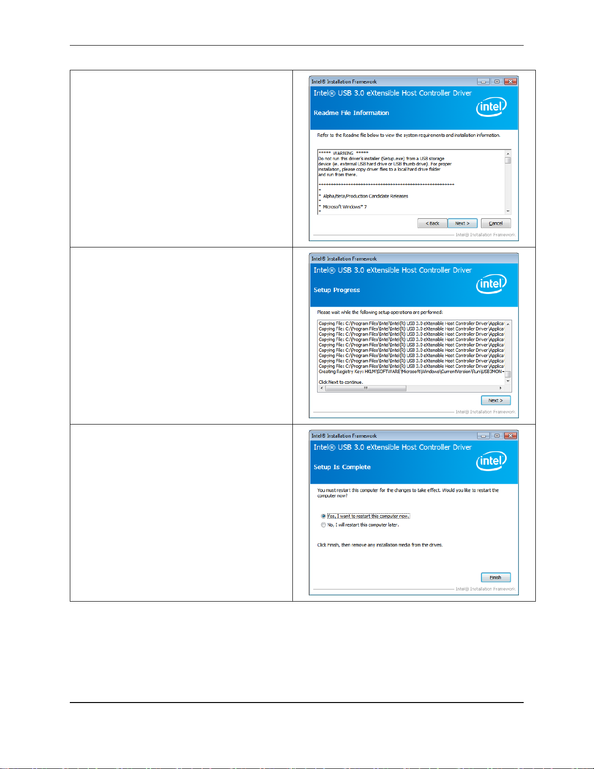
1. Open the following file:
Drivers\USB 3.0\Intel_USB3(Win7)\
Setup.exe
Click “Next” to continue.
2. Read the license agreement. Then click
“Yes” to continue.
USB 3.0 Driver
OMI Operations Manual: OMI6800 Series 41
Page 42
OMI Operations Manual: OMI6800 Series 42
3. Click Next to continue.
4. Click Next to continue.
5. Select “Yes”, I want to restart this
computer now. Then click “Finish” to
complete the installation.
OMI Operations Manual: OMI6800 Series 42
Page 43

OMI Operations Manual: OMI6800 Series 43
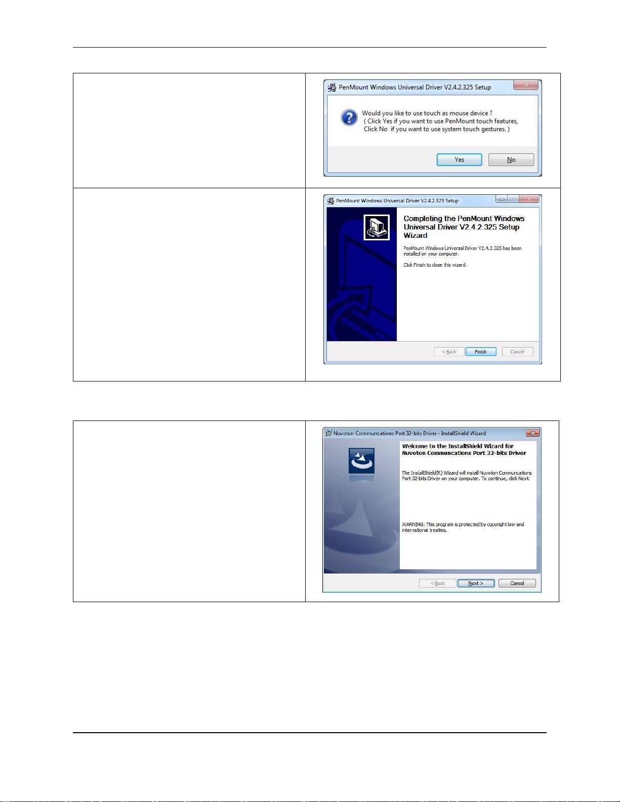
1. Open the following file:
Drivers\Touch Driver\Resistive Touch\
PenMount Windows Universal Driver
V2.4.2.325(WHQL)\Setup.exe
Click “Next” to continue.
2. Read license agreement.
Click “I Agree”.
3. Choose the folder in which to install
PenMount Windows Universal Driver.
Click “Install” to start the installation.
Touch Screen Driver
OMI Operations Manual: OMI6800 Series 43
Page 44
OMI Operations Manual: OMI6800 Series 44
4. Click “Yes” to continue.
5. Click “Finish” to complete installation.
1. Open the following file:
Drivers\Com Driver\Setup.exe
Click “Next” to continue.
COM Driver
OMI Operations Manual: OMI6800 Series 44
Page 45

OMI Operations Manual: OMI6800 Series 45
2. Click “Install”.
3. Click “Finish” to complete the installation.
OMI Operations Manual: OMI6800 Series 45
Page 46

OMI Operations Manual: OMI6800 Series 46
1. Open the following file:
Drivers\Video\Intel
VGA(Win10)win64_153343.4425.exe
Click “Next” to continue.
2. Click “Next” to continue.
3. Click “Yes” to continue.
DRIVER INSTALLATION FOR WINDOWS 10
Video Driver:
OMI Operations Manual: OMI6800 Series 46
Page 47

OMI Operations Manual: OMI6800 Series 47
4. Click “Next” to continue.
5. Click “Next” to continue.
6. Select “Yes, I want to restart this
computer now.”
Click “Finish”.
OMI Operations Manual: OMI6800 Series 47
Page 48

OMI Operations Manual: OMI6800 Series 48
1. Drivers\Intel TXE (Win) \ SetupTXE.exe
Click “Next” to continue.
2. Open the following file:
Click “Next” to continue.
Intel TXE (Win) Driver
OMI Operations Manual: OMI6800 Series 48
Page 49

OMI Operations Manual: OMI6800 Series 49
1. Drivers\Audio\Realtek_Audio(Win7&10)\
Setup.exe
2. Open the following file:
Click “Next” to continue.
3. Select “Yes, I want to restart this
computer now.”
Click “Finish”.
Audio Driver
OMI Operations Manual: OMI6800 Series 49
Page 50

OMI Operations Manual: OMI6800 Series 50
1. Open the following file:
Drivers\Chipset\Chipset_10.0.21_
Public\ SetupChipset.exe.
Click “Next”.
2. Read the license agreement.
Click “Yes” to accept all of the terms of
the license agreement.
3. Click “Next” to continue.
Chipset Driver
OMI Operations Manual: OMI6800 Series 50
Page 51

OMI Operations Manual: OMI6800 Series 51
4. Click “Finish”.
5. Select “Yes, I want to restart this
computer now.”
Click “Finish”.
Touch Screen
The OMI6800 Series includes an analog resistive touch screen. An application is preloaded onto your OMI6800 Series which allows you to calibrate and change the settings of
the touch screen.
Touch Screen Calibration
The touch screen may need to be recalibrated from time-to-time. There are two calibration
methods: ‘Standard Calibration’ and ‘Advanced Calibration’:
Standard Calibration: The simpler of the two methods, this method can be used for
most touch screen calibrations required.
Advanced Calibration: As your OMI6800 ages, the touch screen may require finer
adjustments which can be accomplished using this method.
OMI Operations Manual: OMI6800 Series 51
Page 52

OMI Operations Manual: OMI6800 Series 52
1. Click “Start”, then “All Programs”, and
select “PenMount Windows Universal
Driver (WHQL)”.
Open the “Utility” folder and click
“PenMount Control Panel”
When the PenMount Control Panel
window opens, select “PenMount 6000
USB” and click “Configure”.
2. Select “Standard Calibration” or
“Advanced Calibration”.
“Turn off EEPROM storage”- this option
will disable writing any calibration data
to the EEPROM controller. Default is
enabled.
3. For Standard Calibration:
Click this button and arrows appear
pointing to red squares. Use your
finger or stylus to touch the red
squares in sequence. After the fifth
red point calibration is complete.
OMI Operations Manual: OMI6800 Series 52
Page 53

OMI Operations Manual: OMI6800 Series 53
4. For Advanced Calibration:
Click this button and arrows appear
pointing to red squares. Use your
finger or stylus to touch the red
squares in sequence. After the fifth
red point calibration is complete.
“Plot calibration data”- this option will
display a linearity comparison graph
after calibration is complete. The blue
lines show linearity before while black
lines show linearity after calibration.
1. Touch Mode:
This mode enables and disables the
mouse’s ability to drag on-screen
icons – useful for configuring POS
terminals.
Mouse Emulation – Select this mode
and the mouse functions as normal
and allows dragging of icons.
Click on Touch – Select this mode
and mouse only provides a click
function, and dragging is disables.
Touch Screen Settings
OMI Operations Manual: OMI6800 Series 53
Page 54

OMI Operations Manual: OMI6800 Series 54
2. Beep Mode:
Enable Beep Sound – turns beep
function on and off
Beep on Pen Down – beep occurs
when pen comes down
Beep on Pen Up – beep occurs when
pen is lifted up
Beep on both – beep occurs when
comes down and lifted up
Beep Frequency – modifies sound
frequency
Beep Duration – modifies sound
duration
3. Cursor Stabilizer:
Enable the function support to
prevent cursor shake.
4. Use press and hold as right click
You can set the time out and area for
you need.
OMI Operations Manual: OMI6800 Series 54
Page 55

OMI Operations Manual: OMI6800 Series 55
1. You can use Edge Compensation to
calibrate more subtly.
Touch Screen Edge Compensation
OPERATING SYSTEM OPTIONS
The OMI6800 series OMIs can be purchased with the following operating systems pre-installed:
Windows Embedded Standard 7 (WS7P)
Windows 7 Pro For Embedded Systems (FES7)
Windows 10 IoT Enterprise 2016 LTSB (ESD)
Windows 10 IoT Enterprise Embedded 2016 LTSB (ESD)
Windows Embedded Standard 7
Windows Embedded Standard 7 is a modified version of Windows 7 designed to have a smaller
memory footprint and be less resource intensive then a regular Windows 7 image. Most
applications that are built for Windows 7 Pro will run on Windows Embedded Standard 7.
Windows 7 Professional for Embedded Systems
Windows 7 Professional for Embedded is the same operating system that would be installed on
a typical PC. It provides the most flexibility but will have the largest memory and CPU footprint.
Any software that can run on a Windows 7 PC can be loaded onto an OMI6800 running
Windows 7 Pro.
Windows 10 IoT Enterprise 2016 LTSB
Windows 10 IoT Enterprise LTSB is a full Professional version of Windows 10, available on all
OMI6800 models. This powerful operating system delivers enterprise manageability and
security to IoT solutions. Additionally, all of the features and functionality that customers expect
to find on their desktop PC are available in this version. The Long Term Servicing Branch
OMI Operations Manual: OMI6800 Series 55
Page 56

OMI Operations Manual: OMI6800 Series 56
Operating System
Runtime License*
Target Platform
Windows Embedded
Standard 7
EmbeddedView … for Windows
Embedded
Windows
Windows 7 Pro
… for Windows
Windows
Windows 10 IoT Enterprise
…for Embedded view..for windows
Embedded
Windows
(LTSB) version ensures long term stability that critical production systems require by updating
only necessary operating system components, with significantly fewer update interruptions.
Included Apps:
Internet Explorer
MS Word Viewer
Adobe PDF Reader
MS PowerPoint Viewer
MS Excel Viewer
Media Player
WONDERWARE / INDUSOFT WEBSTUDIO
All of the OMI6800 series Panel PCs are compatible with Wonderware / Indusoft Web Studio.
The choice of operating system will determine the target platform and runtime license required
as shown in the chart below:
* There are multiple options for each operating system indicated by “…” in the chart above.
Refer to the Indusoft Web Studio price list for details.
For Windows Embedded Standard 7 and Window 7 Pro, install Web Studio directly on the Panel
PC. The installer can be transferred with a USB flash drive. It is possible to install only the
runtime files.
For Windows 10 IoT Enterprise LTSB, install the Embedded View runtime by copying
CEServer.exe from your C:\Program Files (x86)\InduSoft Web Studio
v8.1\Redist\WinEmbedded\Bin to the OMI system files.
OMI Operations Manual: OMI6800 Series 56
Page 57

OMI Operations Manual: OMI6800 Series 57
Maple Systems, Inc. | 808 134th St. SW, Suite 120, Everett, WA 98204 | 425.745.3229
Your Industrial Control Solutions Source
_____________________
www.maplesystems.com
1010-1037 Rev. 05
OMI Operations Manual: OMI6800 Series 57
 Loading...