

Page 1

808 134th Street SW, Suite 120 • Everett, WA 98204 • USA • 425/745-3229
Fax: 425/745-3429 • E-mail: maple@maple-systems.com • URL: www.maple-systems.com
87
4
5
Alarm
Ack
9
CLEAR
ENTER
6
Help
1
2
Page
Down
30
F3 F6
F2
F5
Del
F1 F4
Toggle
87
4
5
Alarm
Ack
9
CLEAR
ENTER
6
Help
1
2
Page
Down
30
F3 F6
F2
F5
Del
F1 F4
Toggle
INSTALLATION MANUAL
1010-0105, REV 03
Page 2
2 OIT3160B/4160B
1010-0105, REV 03
COPYRIGHT NOTICE
This manualis a publication of MapleSystems, Inc., and isprovided for use by itscustomers only. The
contents ofthe manual arecopyrighted by Maple Systems,Inc.; reproduction inwhole or inpart, for use
other thanin support ofMaple Systems equipment,is prohibited withoutthe specific writtenpermission
of Maple Systems.
WARRANTY
Maple Systemswarrants each product tobe free fromelectrical and mechanical defectsin materials and
workmanship for a period of two years from the date of shipment. This warranty does not apply to
defects in the Products caused by abuse, misuse, accident, casualty, alteration, negligence, repair not
authorized by Maple Systems, use on current or voltages other than specified by Maple Systems, or
application orinstallation not inaccordance with publishedinstruction manuals. This warrantyis in lieu
of any other warranty either expressed or implied.
Maple Systems’ liability is limited to the repair or replacement of the Product only, and not costs of
installation, removal, or damage to user’s property or other liabilities. If Maple Systems is unable to
repair or replace anonconforming Product, it may offer a refund of the amountpaid to Maple Systems
for such Product infull satisfaction of its warranty obligation. Maximum liability of Maple Systemsis
the cost of the Product.
Information furnished by Maple Systems, Inc., is believed to be accurate and reliable. However, no
responsibility isassumed by Maple Systemsfor the use ofthis information nor forany infringements of
patents or other rights of third parties which may result from its use. No license is granted by
implication, or otherwise, under any patent or patent rights of Maple Systems, Inc. Maple Systems
retains the right to revise or change its products and documentation at any time without notice.
IF SERVICE IS REQUIRED
Package the unit inits original packaging container or, if unavailable,any suitable rigid container. If a
substitute containeris used, surround theunit with shock absorbingmaterial; damage in shipmentis not
covered bythe warranty. Include aletter with theunit describing thedifficulty and designatinga contact
person. Send to the following address: Maple Systems, Inc., 808 134th Street SW,Suite120, Everett,
WA 98204.
Only Products that have been issued a Return Material Authorization (RMA) number from Maple
Systems may be returned. All RMAs must be accompanied with a written purchase order fortracking
purposes or, in the case of out-of-warranty repairs, for repair charges on a time and material basis.
All returns will be tested to verify customer claims of noncompliance with the product warranty.
Improper return packaging which makes verification impossible will void the warranty. Products
passing the tests will be returned “AS IS” to the customer.
If noncompliance is verified and is not due to customer abuse or the other exceptions described with
product warranty, Maple Systemswill, at its option, repair or replace theProduct returned to it, freight
prepaid, which failto comply with the foregoing warranty,provided Maple Systems is notified ofsuch
noncompliance within the one-year warranty period.
APPLICATIONS ASSISTANCE
This manualis designed toprovide the necessary informationfor trouble-free installation andoperation
of your new Operator Interface Terminal (OIT). However, if you need assistance, please call Maple
Systems at 425-745-3229 or visit our web site at www.maple-systems.com.
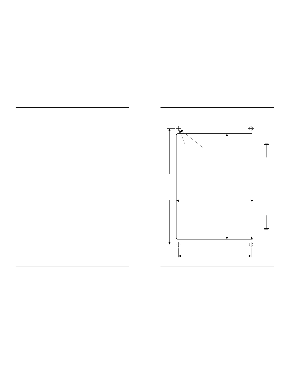
Appendix D
OIT Panel Cutout Dimensions – Front View
INSTALLATION MANUAL 19
1010-0105, REV 03
3.50"
+/-0.01
88.9mm
+/-0.3
0.172" +/-0.01 Dia.,
4.4mm +/-0.3
4Holes
5.10" +/-0.03
129.5mm +/-0.8
5.60" +/-0.01
142.2mm +/-0.3
3.70" +/-0.03
94mm +/-0.8
R0.08" max.
2.0mm
4 Places
Connect mounting
stud(s) to control
panel earth ground
Check Dimension 4.00" [101.6 mm]
Page 3
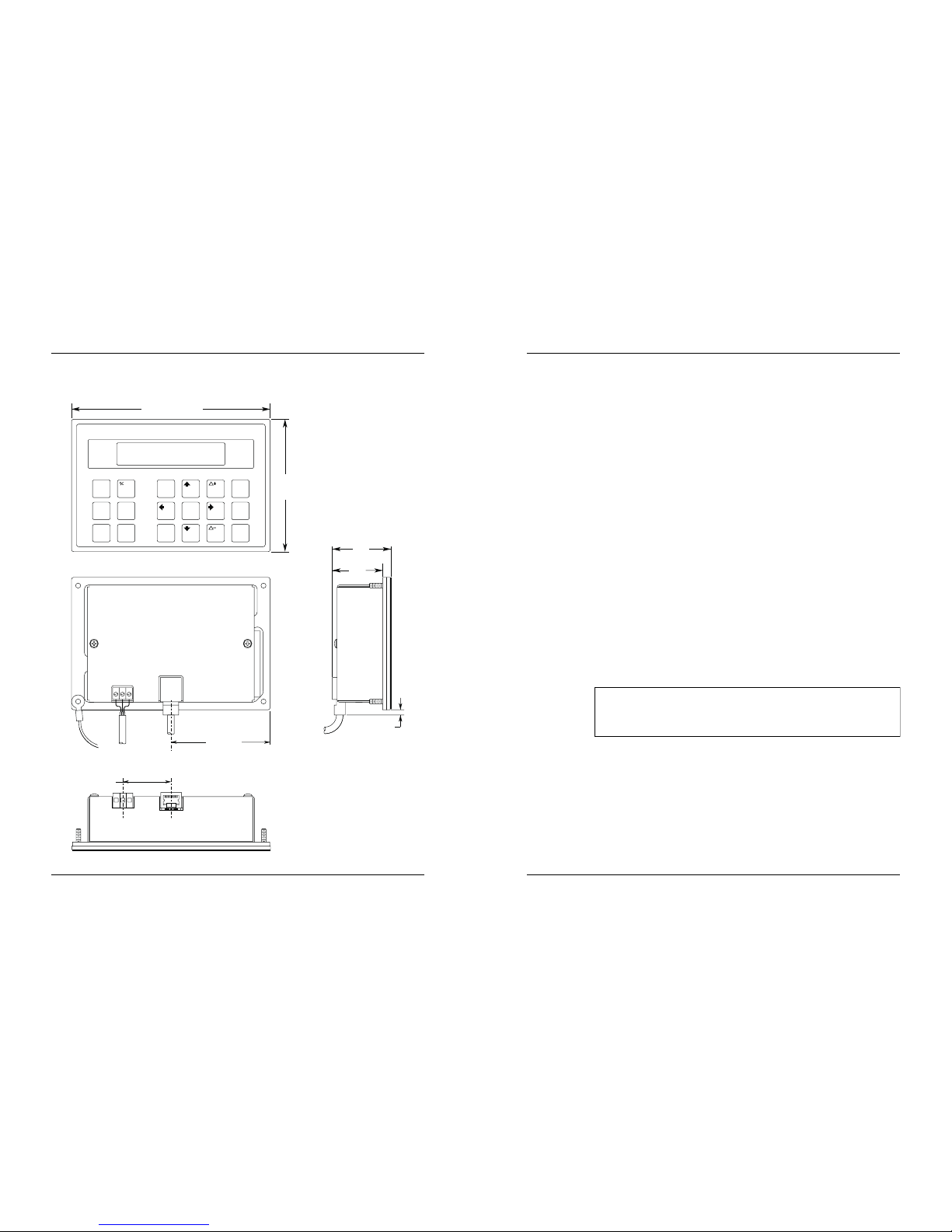
Appendix C
Dimensional Outline
18 OIT3160B/4160B
1010-0105, REV 03
REAR VIEW
SIDE VIEW
4.00
[101.2]
6.00 [152.4]
FRONT VIEW
2
5
Alarm
8
1
F4
F1
F3 F6
F2
F5
7
Help
4
Ack
Del
Toggle
03
CLEAR
ENTER
9
6
Page
Down
BOTTOM VIEW
C
L
3.00 [76.2]
[40.6]
1.60
0.16 [4.1]
[45]
1.77
1.46 [37]
INSTALLATION MANUAL 3
1010-0105, REV 03
Read Me First!
Your new Maple Systems OIT comes from the factory without any
communications protocol or operationalsoftware installed; therefore
•
The OIT will NOT operate until it has been configured using
OITware-200 or STEPware-100.
•
When power is first applied, the OIT’s display will indicate that it
needs to be configured.
•
Use the OITware-200 or STEPware-100 software to create a file
(or “project”) that can be downloaded to the OIT.
•
When the project is transferred, both communications protocol
and operational software are automatically loaded and the unit is
ready for operation.
To ensure that the OIT meets UL and CE compliance, it is
necessary to follow all installation procedures described in this
manual.
Page 4

4 OIT3160B/4160B
1010-0105, REV 03
Introduction
Thank you for purchasing a Maple Systems OIT3160 or OIT4160. You have
selected a rugged, reliable, and powerful operator interface for your application.
This booklet describes the steps necessary to ensure trouble-free OIT system
operation. Please read this booklet carefully!!
Static Awareness
It isbest NOT toremove the rearcover on theOIT. When the rearcover is removed
the circuitryinside is exposed topossible damage by electrostatic discharge during
handling. Minimize the possibility of electrostatic discharge by:
•
Discharging personal static by grounding yourself prior to handling the OIT.
• Handling the OIT at static-free, grounded work station.
• Connecting the chassis of the OIT to a clean ground.
• Placing the OIT into an anti-static bag during transport.
Unpacking the Unit
Carefully unpack the OIT. Please read any instructions or cautions that appear on
the shipping container. Check all material in the container against the enclosed
packing list. Maple Systems, Inc., will not accept responsibility for shortages
against the packing list unless notified within 30 days. The equipment and its
accessories wereinspected and testedby Maple Systemsbefore shipment; all of the
equipment should be in good working order. Examine the equipment carefully; if
any shipping damage is evident, notify the carrier immediately. You are
responsible forclaim negotiations with thecarrier. Save the shippingcontainer and
packing material in case the equipment needs to be stored, returned to Maple
Systems, or transported for any reason.
Appendix B
Agency Ratings
UL Class I, Division 2 Groups A,B,C,D hazardous locations.
Environmental Type 4, 4x (indoor), 12
European Union Directive Compliance
If this product is installed within the European Union or EFTA regions, the following regulations apply:
This apparatus is tested to meet Council Directive 89/336 Electromagnetic Compatibility (EMC) Standards:
• EN50081-2 Class A (Industrial) Emissions
• EN50082-2 Class A (Industrial) Immunity
According to these Standard, the factor which determines, for EMC purposes, whether an apparatus is
deemed to be “industrial” or “Residential, commercial and light industrial”, is given in Clause 1 of
EN50081-2 as follows:
Apparatus coveredby this standard is not intended for connection to a public mains
network but is intended to be connected to a power network supplied from a highor medium-voltage transformer dedicated for the supply of an installation feeding
the manufacturing or similar plant.
The product described in this document is intended for use solely in an industrial environment as defined
above. When installed in Europe, any other application is in contravention of European Union Directives,
and a breach of those laws.
INSTALLATION MANUAL 17
1010-0105, REV 03
Page 5

Appendix A
OIT Hardware Specifications
Mechanical
Material: Aluminum sealed to NEMA 4/12 when panel mounted
Mounting: Panel
Wiring: Unit is field-wired by user to external power plug and shielded RJ-45 communications connectors
Weight: 1 pound (0.45 kg)
OIT3160B Environmental
Operating Temp: +14 to +149°F (-10 to +65°C)
Storage Temp: -22 to +176°F (-30 to +80°C)
OIT4160B Environmental
Operating Temp: +14 to +149°F (-10 to +65°C)
Storage Temp: -40 to +185°F (-40 to +85°C)
Electric Noise Immunity
Emissions: EN55011 (Group 1, Class B)—Generic commercial, light, and heavy industrial environments
EN50081-1—Generic domestic and light industrial environments
EN50081-2—Generic heavy industrial environment
Immunity: EN50082-1—Generic domestic and light industrial environments
EN50082-2—Generic heavy industrial environment
Power Requirements
Input Voltage: +12 to +30 VDC, Class 2
Power Usage: 2.5 watts typical, 3 watts maximum
Display
OIT3160 Display Type: Backlit Liquid Crystal Display (LCD)—5 x 7 dot matrix with cursor
OIT4160 Display Type: Vacuum Fluorescent Display (VFD)—5 x 7 dot matrix with cursor
Display Character Size: 2 lines of 20 characters, 0.19 inches (4.8 mm) high
Display Viewing Angle: Approximately 90 degrees
Keypad
Key Type: Membrane switch with custom legending (all keys)
Feedback: Audible & tactile
Layout: 18 keys with 6 function keys in three rows
Operational Life: Three million operations
Communications
Serial Port: RS-232, RS-422, or RS-485
Baud Rates: 300, 600, 1200, 2400, 4800, 9600, or 19.2k
Internal Features
Memory: 128K x 8 Flash PROM for firmware protocol and configuration data—no battery required
1010-0105, REV 03
16 OIT3160B/4160B INSTALLATION MANUAL 5
1010-0105, REV 03
Table of Contents
1. Safety Warnings ................................................6
1.1. Hazardous Locations ........................................6
2. Control Panel Design Guidelines ...................................7
2.1. Control Panel Grounding ....................................7
2.2. Power Supply Selection .....................................8
2.3. OIT Cable Routing .........................................8
2.4. Other Steps to Improve Noise Immunity ........................9
3. OIT Installation ................................................10
3.1. Prepare Panel for OIT Mounting..............................10
3.2. Enclosures ...............................................10
3.3. Mount OIT to Panel........................................11
3.4. Connect OIT to Power......................................12
3.5. Connect OIT to PLC/Host...................................13
4. OIT Configuration Wiring .......................................14
4.1. Connect OIT to PC for Configuration .........................15
Appendix A: OIT Hardware Specifications .............................16
Appendix B: Agency Ratings ........................................17
Appendix C: Dimensional Outline ....................................18
Appendix D: OIT Panel Cutout Dimensions - Front View .................19
Page 6

1. Safety Warnings
WARNING Hazardous location environment. This unit is suitable
for use in Class I, Division 2 groups A, B, C and D or Non-Hazardous
locations only.
WARNING All input and output (I/O) wiring must be in accordance
with Class I, Division 2 wiring methods and in accordance with the
authority having jurisdiction.
WARNING Explosion hazard. Do not disconnect equipment unless
power hasbeen switched offor the areais known tobe non-hazardous.
WARNING Explosion hazard. Do not connect morethan one main
power supply to any onefuse or circuit breaker.
WARNING Explosion hazard. Substitution of components may
impair suitability for Class I, Division 2.
1.1. Hazardous Locations
Install the MicroOIT terminal using publication NFPA 70E, Electrical Safety
Requirements for Employee Workplaces as a guide. Be certain to follow all
directions for installing and connecting DC power to the MicroOIT.
When used in a hazardous environment, the ultimate enclosure must be in
accordance with Class I, Division 2 wiring methods as described in the National
Electrical Code (ANSI/NFPA 70).
All peripheral equipment must be suitable for the location in which it is used.
Use only a Class 2 power source as described in the National Electrical Code
(ANSI/NFPA 70).
WARNING Use only with Class 2 power source limited to 30 VDC
open circuit and 8A short circuit.
1010-0105, REV 03
6 OIT3160B/4160B
4. OIT Configuration Wiring
The OIT3160and OIT4160 mustbe configured for aparticular protocol beforeuse.
The OITware-200 orSTEPware-100 software (used on a computer with Windows
3.1 or later) is used for OIT configuration. For detailed instructions on installing
and using the software, please refer to the software documentation.
4.1. Connect OIT to PC for Configuration
To configure the OIT using Maple Systems’ configuration software, remove the
PLC/host cablefrom the serialport on theOIT and connectthe OIT to the computer
using an RS-232 serial communications cable (P/N 7431-0096, purchased
separately from Maple Systems). The configuration cable should be connected to
the proper COM porton your computer, thenattached to the serialport on the OIT.
See Figure 7 below for serial port pin assignments.
INSTALLATION MANUAL 15
1010-0105, REV 03
CTS
DSR
RTS
DCD
DTR
8
7
6
4
1
RXD
TXD65
RJ-45
OITPC
4
Return
Ground
5
TXD
3
RXD 2
9S
1TXD+
2TXD-
3CTS
7RXD-
8RXD+
N/C
N/C
N/C
N/C
N/C
9
N/C
Top
8
1
8
1
Pin Configuration
RJ-45 Plu
g
Printer
Com2
Bac
k
of
OIT
7431-0096
Com1
OIT
PC
OIT Power Supply
Power
Maple Systems
OIT to PC cable
(If mouse is using
Com 1, use Com2)
Figure 7 OIT3160/4160 to PC RS-232 Communication
Page 7

3. Route the communication cable to the PLC/host. Refer to the “OIT Cable
Routing” section for more information.
4. Connect the other end of the cable to the PLC/host and tighten the cable screws.
5. Connect the green shield wire from the cable to earth ground (chassis
ground) on the PLC. If this wire is not present, the ground connection was
made inside the connector.
1010-0105, REV 03
14 OIT3160B/4160B
PIN# FUNCTION
1 TXD+
2 TXD3 CTS
4 RETURN
5 TXD
6 RXD
7 RXD8 RXD+
Figure 6 Port 1 Pin Outs
2. Control Panel Design Guidelines
The following guidelinesare intended to illustrate proper installationof the OIT to
help minimize electrical noise, which may hamper normal operation. It is the
responsibility of the customer to ensure that all wiring and other components
used in the control system meet Class I, Division 2 requirements. This
installation manual is intended only asa general guide to beused in conjunction
with the appropriate Class I, Division 2 installation and wiring requirements.
The customer is ultimately responsible for proper installation.
Pay careful attention to the placement of system components and associated cable
routing. These items can significantly enhance the performance and integrity o
f
your control application.
2.1. Control Panel Grounding
•
The control panel should be connected to a good, high-integrity earth ground
both for safety considerations and shielding purposes. This must be a reliable
earth ground with a low-resistance path. The ideal earth ground would be a
copper grounding rod located close to the OIT and the control panel.
•
Hinged doors on controlpanels do not provide along term electricalconnection
to the rest of the enclosure. Corrosion develops over time and prevents good
electrical contact. For thisreason, a separatewire braid should be installed from
the hinged control panel to the rest of the enclosure.
1010-0105, REV 03
INSTALLATION MANUAL 7
Figure 1 Control Panel Example
Page 8

2.2. Power Supply Selection
•
The power supply used to power the OIT should have an output between +12
and +30 VDC, meeting Class 2 power requirements. The voltage should
measure between +12 and +30V at the OIT between Pins 1 and 2 of the power
connector. A 24 VDC, 1.2 amp linear power supply dedicated to the OIT is
recommended.
•
The powercable for theOIT should be18AWG 2-conductor stranded wire with
a shield wire and protective shield (foil or braid). The shield of the OIT power
cable mustbe connected to earthground at bothends of thecable. Please refer to
the “Connect OIT to Power” section for more information.
•
A power line filter installed at the AC input to the OIT power supply is highly
recommended asa safeguard against conducted RFnoise, which isoften present
on factory power lines. The wires connecting the outputof thepower line filter
to the power supply should be kept as short as possible to minimize any
additional noisepickup. The case of thepower linefilter should be connected to
a quietearth ground. The power linefilter should havea current ratingof at least
three amps with common mode and differential mode attenuation.
• The power supply that provides power to the OIT should not be used to power
switching relaysor solenoidsunlessnoise filter capsare connectedto each relay.
2.3. OIT Cable Routing
•
Input and output (I/O) wiring must be in accordance with Class I, Division 2
wiring methods and in accordance with the authority having jurisdiction.
•
Always routethe OIT communicationcable and power cableaway from anyAC
voltage or PLC/host control wires.
•
Never bundle the OIT cables together with120 VAC power wires or with relay
wiring.
•
Try to keep at least 8 inches (20 cm) of separation between the OIT cables and
other power wiring. If voltages greater than 120 VAC are used in the system,
greater separation is required.
•
If theOIT cablesmustcome near ACwiring, make surethey crossat 90 degrees.
•
Running ACpower wires ina separate groundedconduit is the preferredmethod
for electrical noise reduction.
1010-0105, REV 03
8 OIT3160B/4160B
Figure 2 Power Line Filter Connection
2. Install the wires into the Class 2 power supply as follows (colors shown are
for Maple Systems Cable P/N 6030-0009):
COLOR POWER SUPPLY OIT
Red + Output (+)
Black - Output (-)
Shield Wire Case Ground Shield
NOTE: The power connector on the OIT has M3 slotted screws.
3.5. Connect OIT to PLC/Host
Each PLC/host supported by Maple Systems has its own wiring requirements.
Maple Systems offers pre-constructed OIT-to-PLC communication cables for
most PLCs. Most cablesare available for sameday shipment fromMaple Systems.
They arebuilt and tested for high reliabilityand are stronglyrecommended. Maple
Systems also builds custom cables—contact the factory for information.
Components and instructions necessary to construct your own OIT-to-PLC
communications cables are also available. Refer to Maple Systems’ Price List or
web site (www.maple-systems.com).
NOTE: Refer tothe ASCII SlaveProtocol Guide or theSTEP1 Protocol Operation
Manual for information on constructing OIT-to-ASCII host communication
cables.
STEPS
1. Connect the RJ-45 plug end of the communication cable into the serial port
on the OIT.
2. Ensure that the locking tab has secured the plug.
1010-0105, REV 03
INSTALLATION MANUAL 13
Figure 5 OIT3160/4160 PLC Connection
Page 9

3.4. Connect OIT to Power
WARNING Use only with Class 2 power source limited to 30 VDC
open circuit and 8A short circuit.
The power cable for the OIT should be 18AWG 2-conductor wire with a shield
wire and protective shield foil. Maple Systems sells cable P/N 6030-0009 by the
foot for user-built power cables.
STEPS
1. The power cable should not be any longer than necessary. Prepare the
cable as follows:
a) Cut the power cable to the appropriate length.
b) Strip the cable shield back to expose the two insulated wires and the
bare shield wire on both ends of the power cable.
c) Strip the insulation from the two insulated wires. For the OIT end, this
is 0.27 inch (7 mm).
1010-0105, REV 03
12 OIT3160B/4160B
Figure 4 OIT3160/4160 Power Supply Connection
•
Keep thelengths of the OITcables as shortas possible. Do not coilexcess cable
and place it next to AC powered equipment.
2.4. Other Steps to Improve Noise Immunity
•
Always install the OIT’s rear cover. This provides a shield against electrical
noise whichcan be generatedin the controlpanel by relays, motors,power lines,
and/or high frequency equipment. Ensure that all rear cover mounting screws
are properly secured.
•
Any equipment used in the enclosure that operates at high frequency or high
current levels can be covered with a grounded metal shield.
INSTALLATION MANUAL 9
1010-0105, REV 03
Page 10

3. OIT Installation
It is necessary to follow all installation procedures described in this chapter for
electrical noise immunity and CE compliance.
Your Maple Systems OIT is designed to connect easily to your PLC. External
connectors provide quick connection for power and communications wiring.
•
There isone serial port with an RJ-45shielded jack. This port is used toconnect
to the PLC and to configure the OIT.
•
A separate three-position terminal block is supplied to provide power to the
OIT.
3.1. Prepare Panel for OIT Mounting
The OIT3160 and OIT4160 are mounted to a control panel from the front. For a
proper NEMA 4/12 seal, you will need:
• A panel with a maximum thickness of 0.125 inches (3.2 mm).
• A panel with a minimumthickness of 16-gauge (0.059 inches; 1.5 mm)steel or
10-gauge (0.102 inches;2.6 mm) aluminum. Thinner panels may bow between
the mounting studs, requiring the use of a stiffener on the rear.
• The surface of the panel, where the panel comes into contact with the gasket,
must be free of scratches, pits, and other features that prevent the gasket from
sealing properly.
The diagram inAppendix D shows the dimensionsof the panel cutout required for
proper installation. This panel cutout illustration is shown actual size and can be
photocopied to be used as a template. Check photocopy accuracy with the printed
check dimension. The panel cutout should becleaned and deburred before the OIT
is installed.
3.2. Enclosures
Allow enough spacing within an enclosure for adequate ventilation. For some
applications, you may have to consider heat produced by other devices within a
panel. The ambient temperature around the terminal must be maintained as
specified.
10 OIT3160B/4160B
1010-0105, REV 03
3.3. Mount OIT to Panel
STEPS
1. Gently position the OIT with the studs through the panel mounting holes.
2. Secure the OIT by installing the four #6-32UNC mounting nuts using a
5/16 inch socket wrench or nut driver.
CAUTION: Do not torque the 4 mounting nuts to over 15 pound-inches. Ove
r
torquing can strip the threads or pull the studs loose.
RE-INSTALLING: Because the gasket will take a “set” to the panel, be sure to
re-install any OIT to the same panel cutout when a NEMA 4/12 seal is required.
1010-0105, REV 03
INSTALLATION MANUAL 11
Figure 3 OIT3160/4160 Panel Mounting
 Loading...