

Page 1

Table Of Contents
GETTING STARTED .....................1
What You Will Need ..................1
Step 1: Install the MAPware 100
Configuration Software ................1
Step 2: Create Your First MAPware 100
Project.............................4
Step 3: Connect the Operator Interface
Terminal to the PC ....................6
Step 4: Send Your Project to the Operator
Interface Terminal ....................7
Step 5: Connect the Operator Interface
Terminal to the PLC ...................7
Conclusion .........................8
OPERATION...........................9
Menu Bar ..........................10
Tool Bar............................10
New Project ......................11
Open Existing Project ...............11
Print Project ......................12
Save Project......................12
Cut ............................13
Copy ...........................13
Paste ...........................13
Align Left, Center, Right .............13
Clear Current Message ............14
Blink ...........................14
Insert Special Character .............14
Register Monitor Editor..............16
Example Group Box .............17
Data Group Box................17
Field Attributes Group Box ........18
Limits Box ....................19
ASCII Table Button..............20
Go To Message ...................21
Configuration Editor ...............21
OIT - PLC Interface Settings
Group Box ....................22
OIT Options Group Box ..........22
Function Key Editor ................24
Communication Options ............25
Read from OIT ....................26
Send to OIT ......................27
Help ...........................28
OIT/PLC Identification .................28
Basic Screen Characteristics .............28
Message Editor ...................29
Message Scroll Bar.................29
General Options Group Box..........29
OIT Memory Used Group Box............30
Message Utilization ...................30
TROUBLE SHOOTING ...................32
MAPware 100 Does Not Transfer a
Project to the OIT..................32
OIT Screen is Blank and the OIT is
Beeping .......................32
The OIT Does Not Attach to the PLC..32
Information in this document is subject to change without notice. No part of this document may be reproduced or transmitted in any
form or by any means, electronic or mechanical, for any purpose, without the express written permission of Maple Systems, Inc.
© 1997 Maple Systems, Inc.
Microsoft and MS-DOS are registered trademarks, and Windows is a trademark of Microsoft Corporation.
Page 2

MAPware 100 User's Guide 1
The MAPware 100 User’s Guide explains how to install and use the MAPware 100 configuration software
and how to get your MAP Family Operator Interface Terminal up and running. It also includes a trouble
shooting chapter that covers some of the most common problems encountered when configuring a MAP
Family Operator Interface Terminal. In addition, we recommend you read the following:
Installation Manual–Covers the installation requirements of your specific MAP Family Operator
•
Interface Terminal. Each member of the MAP Family has a manual written specifically to its unique
specifications (shipped with each OIT).
MAP Family Operation Manual (PLC Protocols)–Covers the general operation and features of the
•
MAP Family whenthe PLC protocolsare used (shippedwith the MAPware100 configuration software).
Protocol Guides–Covers information relating to the use of your MAP Family Operator Interface
•
Terminal specific to each protocol (shipped with the MAPware 100 configuration software).
GETTING STARTED
This chapter shows you how to install the MAPware 100 configuration software, how to
create your first MAPware 100 project, how to download your project to a MAP Family
Operator Interface Terminal, and how to connect your MAP Family Operator Interface
Terminal to your PLC. If you follow each step correctly, you will have a functioning MAP
Family Operator Interface Terminal. If you encounter any problems, please contact your
local distributor or Maple Systems Technical Support at 425-486-4477.
What You Will Need
The table, below, lists the items necessary to program a Maple Systems MAP Family Operator
Interface Terminal and then connect it to your PLC.
MAP460D MAP320D, MAP340D
Configuration Software MAPware 100 MAPware 100
Configuration Cable (OIT to PC) 7431-0048 7431-0049
Personal Computer* User Provided User Provided
Power Cable Not Required 7431-0050A
1/2 Amp, 24 VDC Power Supply** User Provided User Provided
Programmable Logic Controller User Provided User Provided
Communication Cable (OIT to PLC)
See the Selection Table for Cable Accessories in
the appropriate Installation Manual
* Computer requirements include at least a 486SX/33MHz PC, 4MB RAM, 4MB available
hard disk space,VGA graphics card,Microsoft Windows 3.1,and one availableserial port.
** The MAP340D require a fast start power supply.
Step 1: Install the MAPware 100 Configuration Software
1. Start Windows.
Note: If any application programs are running, shut them down and restart Windows before
installing the MAPware 100 configuration software.
1010-0089, REV00
2. Place the MAPware 100 Setup Disk into your 3.5-inch floppy drive.
3. From the File menu in the Windows Program Manager, choose Run (For Windows 95:
From the task bar, choose Start then Run).
Page 3

2 GETTING STARTED
4. Enter a:\setup (Substitute B for A if your 3.5-inch floppy drive is configured as a B
drive).
5. Choose the OK button.
6. The Setup program starts. Depending on your computer, this can take a few seconds.
7. Setup then prompts you for the location of the setup data files. Select the disk drive
which contains the setup disk (usually A:\).
8. Setup then prompts you for the destination directory for the MAPware 100 files. The
default is C:\MAPWARE.
1010-0089, REV00
9. If any other application programs are currently running under Windows, the
following message box will appear. It is strongly recommended that you shut down
any active programs (except video). If you do not, a setup error can occur.
Page 4

MAPware 100 User's Guide 3
10. Setup will then show you total space required and space available for installation of
MAPware 100. Choose the Continue button. If adjustment is needed select Exit
Setup.
11. The MAPware 100 Setup will now start to transfer files to selected areas on the hard
disk. It will create the subdirectory specified in step 8. It will also place files into the
WINDOWS and WINDOWS\SYSTEM subdirectories. A dialog box will indicate the
files being transferred and the percentage of the file transfer complete. A MAPware
100 program group and program items will be created. You can run MAPware 100
from this program group or move the icon to another group later. Finally, MAPware
100 makes use of Display Specific Fonts (DSF). In order for MAPware 100 to use
these fonts, they are transferred into the WINDOWS\SYSTEM subdirectory and your
Windows WIN.INI file is updated.
12. Once the installation is complete, you are asked if you want to restart the computer or
continue with the current Windows session. MAPware 100 will not operate correctly
until the computer is restarted. Choose the Reboot Computer button.
Note: In rare cases, your computer may not restart properly. If this happens, simply reboot
your computer.
13. A new Windows Program Group entitled Maple Systems MAPware 100 has been
created which contains MAPware 100 and MAPware Setup. Remove the floppy disk
and store it in a safe place.
1010-0089, REV00
Page 5

4 GETTING STARTED
Step 2: Create Your First MAPware 100 Project
1. Double click on the MAPware 100 icon in the Windows Program Manager.
2. MAPware 100 starts and, after a few seconds, the MAPware 100 dialog box appears
(see Figure 1). In the center of the MAPware 100 dialog box is a representation of the
OIT display. From the File menu, choose New.
Figure 1 MAPware 100 Dialog Box
3. The New Project dialog box appears. Select the desired OIT and PLC from the OIT
Type and PLC Type list boxes (see Figure 2). It is very important to select the proper
OIT and PLC.
Figure 2 New Project Dialog Box
4. Once the OIT and PLC have been selected, choose the Start New Project button.
1010-0089, REV00
Page 6

MAPware 100 User's Guide 5
5. The Configuration Editor dialog box appears (see Figure 3). This dialog box allows
you to tailor your MAP Family Operator Interface Terminal to your PLC. To accept
the default values, choose the Done button.
Figure 3 Configuration Editor Dialog Box
6. You are now back in the MAPware 100 dialog box. Type an appropriate message into
the Message text box (see Figure 4).
1010-0089, REV00
Figure 4 Message Text Box in MAPware 100 Dialog Box
7. In the General Options group box, select the Start Up Message check box.
8. From the File menu, choose Save As.
Page 7

6 GETTING STARTED
9. The Save As dialog box appears. Type firstoit.mwr into the File Name text box.
Figure 5 Save As Dialog Box
10. Choose the OK button. You have now created your first MAPware 100 project.
Step 3: Connect the Operator Interface Terminal to the PC
PC
OIT
Port 1 Power
7431-0050A
Port 1
Power
OIT
7431-0048
/
MAP320D
MAP340D
MAP460D
OIT Power
Supply
+
GND
-
OIT Power
Supply
+
GND
-
Com2
PC
Com2
Pr int er
Pr int er
Com1
Maple Systems
OIT to PC cable
(If mouse is using
Com 1, use Com2)
Com1
(If mouse is using
Com 1, use Com2)
(Rear of
OIT)
7431-0049
(Rear of
OIT)
Maple Systems
OIT to PC cable
1010-0089, REV00
Figure 6 OIT to PC Wiring Configurations
Page 8

MAPware 100 User's Guide 7
Step 4: Send Your Project to the Operator Interface Terminal
1. Apply 24 VDC to the OIT. At this point the OIT will display the following messages:
***System is not configured!*** and Press ANY key to enter download mode.
Press a key on the OIT keypad. The message indicates that the OIT is ready to receive
a project from MAPware 100.
2. In MAPware 100, from the Transfer menu, choose Send to OIT.
3. The Send To OIT dialog box appears (see Figure 7). If you are using a serial port other
than COM 1, choose the Options button.
4. The Communication Options dialog box appears (see Figure 7). In the PC Serial Port
group box, select the option button for the COM port you are connected to and then
choose the Done button.
Figure 7 Send to OIT & Communication Options Dialog Box
5. You are now back in the Send to OIT dialog box. Choose the OK button.
6. MAPware 100 will now send the entire OIT project file to the OIT. The project
transfer will take a couple of minutes. When the transfer is complete MAPware 100
will restart the OIT. The OIT will then attempt to attach to the PLC.
Step 5: Connect the Operator Interface Terminal to the PLC
1. Connect the OIT to your PLC as per the installation manual supplied with your OIT.
2. Make sure you use the correct cable to connect the OIT to your PLC. Contact your
local distributor or Maple Systems Technical Support if you need assistance in
choosing the appropriate cable.
3. When the OIT attaches to the PLC, the startup screen you created in your first project
appears on the screen.
1010-0089, REV00
Page 9

8 GETTING STARTED
PLC
OIT
Port 1
Power
MAP320D
OIT Power
Com Port
(Rear of
OIT)
Supply
MAP340D
GN D
+
-
Maple Systems
OIT to PLC cable
7431-0050A
MAP460D
Conclusion
You have now created your first MAP Family Operator Interface Terminal project. Please
take the time to review all the documentation provided, as we are sure you will want to
explore all the capabilities of your new MAP Family Operator Interface Terminal. If you
encountered any difficulties or questions downloading your MAP Family Operator Interface
Terminal project, please contact your local distributor or Maple Systems Technical Support
at 425-486-4477.
PLC
Com Port
OIT Power
Supply
+
GN D
-
Figure 8 OIT to PLC Wiring Configurations
Maple Systems
OIT to PLC cable
(Rear of
OIT)
OIT
Port 1
Power
/
1010-0089, REV00
Page 10

MAPware 100 User's Guide 9
OPERATION
Since MAPware 100 has been designed to run under the MicrosoftWindows environment, it
conforms to the Windows user interface standard. Many of the tools on the tool bar are
identical to other software packages such as Microsoft Word and Excel. The pull down
menus all operate according to the Windows standard, they may be selected using the mouse
or through the appropriate Alt sequence (i.e. Alt+F for the File menu).
As with many Windows programs, depending on the options selected at any one time, some
functions are no longer valid. These functions are deselected or grayed out so that they are
not accessible when their use is not appropriate. For example, on the main MAPware 100
dialog box, if the Chain check box is selected in the Extensions group box the Message box is
activated. If the Chain check box is disabled, the Message box is grayed out.
The illustration below outlines the major features of the main MAPware 100 dialog box:
Title Bar
Menu Bar
Tool Bar
OIT Identification
PLC Identification
Message Editor
Message Scroll Bar
General Options
Group Box
•
Title Bar: Identifies the file name for the current project.
•
Menu Bar: Provides pull-down menus for accessing functions (pg. 10).
•
Tool Bar: Provides buttons that can be used as shortcuts to choosing functions from the
OIT Memory Used
Group Box
menus (pg. 10).
•
OIT Identification: Identifies the OIT model selected for the current project (pg. 28).
•
PLC Identification: Identifies the PLC model the OIT is being configured to work with
for the current project (pg. 28).
•
Message Editor: Area used to enter OIT text and register monitors for each stored
message (pg. 29).
•
Message Scroll Bar: Scrolls through the stored messages (pg. 29).
•
General Option Group Box: Grouping of options that can beapplied to stored messages
(pg. 29).
•
OIT Memory Used Group Box: Indicates the amount of OIT configuration memory
remaining and the correct date and time. (pg. 30)
1010-0089, REV00
Page 11

10 OPERATION
Menu Bar
The menu bar contains all of the menus that can be used to navigate through the program.
Accessing the menusis simple: either pointto one with themouse and click onit, or pressand
hold the Alt key while pressing the first character in the menu name (example: F for File).
Many of the items in the menus may be accessed directly using the associated control keys as
indicated to the right of the menu item. Once the menu drops down, use the mouse or cursor
keys to point to the desired menu item, then click on the item with the mouse, or press Enter
on the keyboard to select the menu item.
Tool Bar
The tool bar contains tools, or buttons, that provide a much quicker way of performing
functions than using the pull-down menus. Some examples include cutting and pasting
screen information, saving the current project, and placing register monitors onto the screen.
Hints explaining a button’s purpose appear if the cursor is placed over a button.
New
Project
Open
Existing
Project
Print
Project
Clear Current
Align
Right
Screen
Insert Special
Character
Register Monitor
Blink
Paste
Cut
Copy
Save
Project
•
New Project: Creates a new project (pg. 11).
•
Open Existing Project: Opens existing project (pg. 11).
•
Print Project: Sends project to printer for hard copy output (pg. 12).
•
Save Project: Saves changes made to active project (pg. 12).
•
Cut: Cuts selected text or objects from the active message (pg. 13).
•
Copy: Copies selected text or objects from the active message (pg. 13).
•
Paste: Pastes previously cut or copied text or objects into the active message (pg. 13).
•
Align: Aligns text to the left margin, right margin, or centered in the display (pg. 13).
•
Clear Current Screen: Clears all information from the active message (pg. 14).
•
Blink: Controls blinking feature (pg. 14).
•
Insert Special Character: Allows special OIT-dependent characters to be inserted onto
Align
Center
Align
Left
Editor
Go To
Message
Configuration
Function Key
Editor
Editor
Read
from OIT
Send to
Communication
Options
message (pg. 14).
•
Register Monitor Editor: Enables PLC register monitors to be attached to the active
message (pg. 16).
•
Go To Message: Finds desired message (pg. 21).
•
Configuration Editor: Sets up system-wide parameters (pg. 21).
•
Function Key Editor: Enables configuration of the function keys (pg. 24).
•
Communication Options: Configures parameters of communication between
MAPware and the OIT (pg. 25).
•
Read from OIT: Reads a project from the OIT (pg. 26).
Help
OIT
1010-0089, REV00
Page 12
MAPware 100 User's Guide 11
Send to OIT: Sends a project from MAPware 100 to the OIT (pg. 27).
•
Help: Context-sensitive help (pg. 28).
•
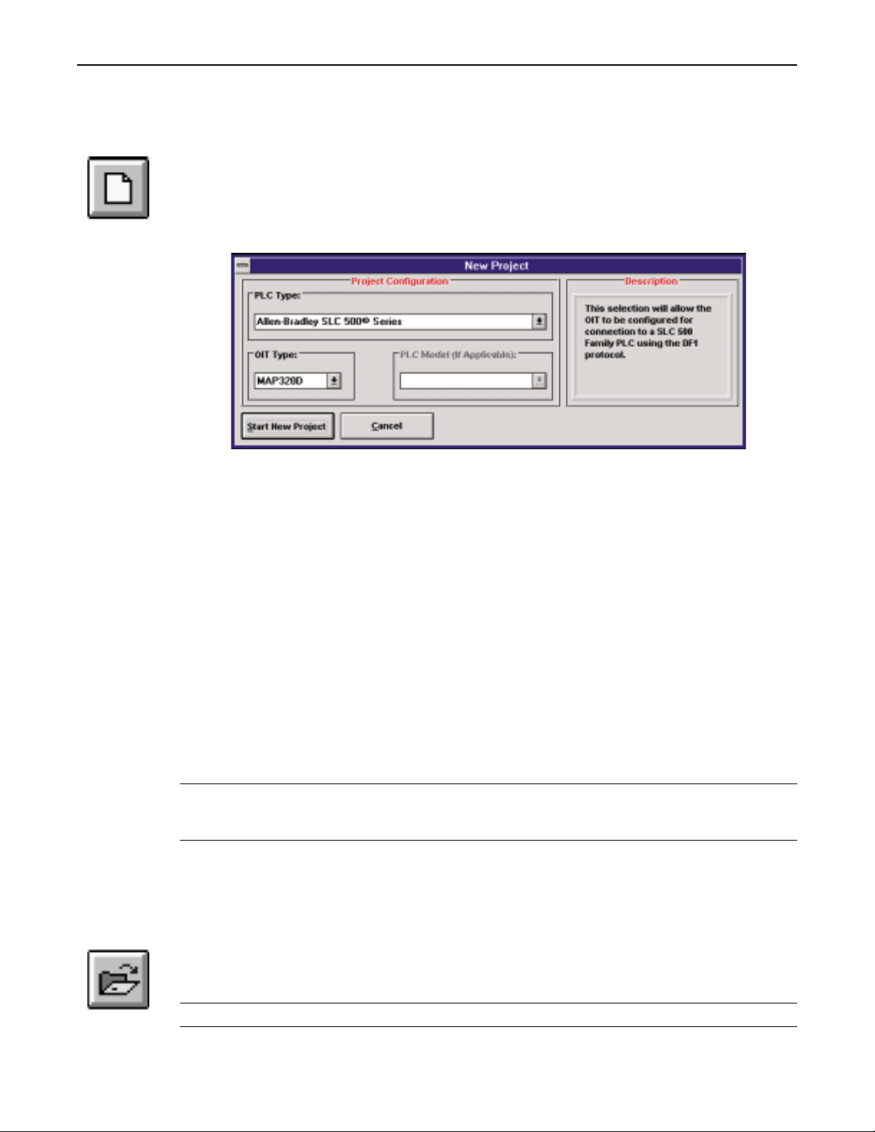
New Project
The New Project button is the shortcut for the File/New menu item. Clicking on this button with
the mouse will cause MAPware 100 to start a new project. If a project is currently loaded and it
has changed, you will be asked if you wish to save the existing project before starting a new one.
If you select NO, the edited project will be lost. The following dialog box will appear:
Select the PLC that the OIT will be connected to using the select box in the PLC Type group.
To do this, place the cursor on the down arrow and click on the left mouse button. The Select
box will drop and display a list of the currently supported PLCs from which you can choose.
Using the mouse, scroll through the selection and double click on the desired PLC protocol
driver. Some PLC families have models with varying memory configurations. If this is the
case on the selected PLC protocol driver, the Model group will be enabled. In a similar
fashion to selecting a PLC protocol driver, use the mouse to select the specific PLC model
the OIT will be connected to.
As various PLC protocol drivers are selected, a description of the protocol and PLC family
will appear on the Description group. This is information only and may be used to help
identify the proper protocol driver for a particular PLC. More information about the PLC
protocol driver specifics may be found by clicking on the Help button.
Once you are satisfied with the selected PLC protocol driver, click on the Start New Project
button to begin a new project file. If you do not wish to change protocol drivers at this time,
click on the Cancel button.
Note: The MAPware 100 software always starts up with a default protocol selected.
Therefore, it is important to select the New button and choose the appropriate PLC
protocol before screen data is entered.
Since screen data information varies with the PLC protocol used, any project created for a
particular PLC protocol cannot be transferred to another project using a different PLC
protocol.
Open Existing Project
The Open Existing Project button is the shortcut for the File/Open menu item. This button is
used to load from disk a previously saved project file.
Note: All projects use the .mwr extension.
1010-0089, REV00
Page 13
12 OPERATION
Project files may be stored anywhere on your computer system. Use the Drives and
Directories box for selecting the proper path. Projects that have previously been saved in the
selected directory will be displayed in the File Name list box. Use the mouse to select a file
name and click on the OK button to load the project. Click on the Cancel button to abort
loading a project file.
Note: MAPware 100 remembers your last 4 projects.
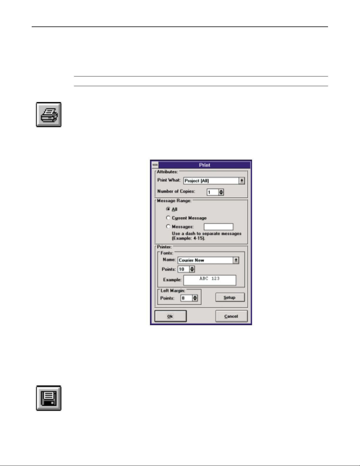
Print Project
The Print Project button is the shortcut for the File/Print menu item. This button allows you
to print the currently loaded project. All of the PLC communication parameters and message
text are printed. The message text is printed in the order that the messages are chained so that
the listing may be used for debugging the system.
The Print dialog box only appears if the File/Print menu item is selected. The Print dialog
box does not appear if the Print Project button is chosen.
Save Project
1010-0089, REV00
Upon the starting of MAPware 100 for the first time, the software will detect if there is a
MAPware 100 INI file (there will not be). The software will then search the system for the
font closest to Courier and default to that (Courier is recommended since it is a TrueType
font). The margin will default to 10 points. Subsequent activation will pull the font and
margin in from the MAPWARE.INI file.
The Save Project button is the shortcut for the File/Save menu item. This tool button will
save the current project. If the projecthas previously been saved, theSave button will simply
update the contents of the project file on disk. If this is the first time for the file to be saved,
you will be presented with a screen that allows you to enter the project’s name as well as the
location to save the file to.
Page 14

MAPware 100 User's Guide 13
While you are working on a project, all of the data entered is temporarily saved within the
PC’s memory. Nothing is saved permanently until the Save or Save As command is
executed. You should save often to ensure that you don’t lose valuable information.
Cut
The Cut button is the shortcut for the Edit/Cut menu item. The Cut button will clip out the
highlighted area on the message entry window and place it onto a clipboard so that it may be
pasted at a later time. To highlight an area of the message, use the mouse to place the cursor
on the message and press the left mouse button. While holding the button, drag the mouse
across the area you wish to cut or remove from the message. The selected message area will
become highlighted as the mouse is moved. Release the left mouse button to stop selecting.
Clicking on the Cut button will now remove the selected message information and place it
onto the clipboard for later pasting. Only the last cut section of the message may be pasted
onto the same message or another.
Since register monitors on the message are objects, entire register monitors must be
highlighted before they can be cut.
Copy
The Copy button is the shortcut for the Edit/Copy menu item. The Copy button will place a
copy of the highlighted area of the message entry window onto a clipboard so that it may be
pasted at a later time. To highlight an area of the message, use the mouse to place the cursor
on the message and press the left mouse button. While holding the button, drag the mouse
across the area you wish to copy from the message. The selected message area will become
highlighted as the mouse is moved. Release the left mouse button to stop selecting. Clicking
on the Copy button will now copy the selected message information and place it onto the
clipboard for later pasting. As with cutting text, only the last copied section of the message
may be pasted onto the same message or another.
Register monitors are objects on the message. Only by highlighting the entire register
monitor will it be copied to the clipboard when executing this command.
Paste
The Paste button is the shortcut for the Edit/Paste menu item. The Paste button is used in
conjunction with the Cut or Copy buttons to move data on the message or to repetitively place
identical copies of text and register monitors onto any number of OIT messages. Text and register
monitors that are cut or copied are placed on the clipboard which may be pasted at will. Pasted text
and register monitors will appearstarting at the cursor location andmay be pasted multiple times.
Register monitors that are pasted to the message will create a duplicate, but unique, register
monitor on the current message. Changes made to the new register monitor(s) will not affect
the copied register monitors.
Align Left, Center, Right
The Align Left, Align Center, and Align Right buttons are the shortcuts for the Edit/Align
Left, Edit/Align Center, and Edit/Align Right menu items. These buttons allow aligning a
line on the project. Click on the alignment desired—left, centered, or right alignment—and
the MAPware 100 software will move the text and Register Monitors accordingly.
1010-0089, REV00
Page 15

14 OPERATION
Clear Current Message
The Clear Current Message button is the shortcut for the Edit/Clear Message menu item. The
Clear Current Message button is used to clear the entire contents of the current message. All
text, attributes and register monitors will be deleted from the message.
Blink
The Blink button is the shortcut for the Edit/Blink menu item.Each character on the message
may have its blink attribute enabled causing the character to blink at a rate of once per
second. In addition to characters on the message, some register monitors can also have the
blink attribute enabled.
Using the mouse, placethe cursor on the character to enable blinking on, or highlight the area
of text to blink. Click on the Blink button and notice that the blink attribute is enabled on the
selected characters (they will all blink). To enable the blink attribute on a register monitor
field, select all of the characters within the register monitor field and click on the Blink
button. Disabling the blink attribute is done the same way. Use the mouse to highlight the
characters that have the blink attribute enabled and click on the Blink button again.
Insert Special Character
The Insert Special Character button is the shortcut for the Insert/Special Character menu
item. The OITdisplay is capableof displaying manymore characters thanmay be enteredvia
the PC keyboard. The Insert Special Character button is used to access the other characters
that cannot be typed in. These characters include special symbols and foreign characters.
Note: The Special Character sets vary depending on the OIT model. Please refer to the figures
at the end of this section for the special characters available on your OIT.
To insert aspecial character, click onthe Insert SpecialCharacter button with themouse. The
following dialog box will appear:
1010-0089, REV00
Page 16

MAPware 100 User's Guide 15
Characters can be selected in two ways: By double-clicking on the desired character, or by
clicking once on the desired character and then clicking on the Add to List button. The
selected character will be displayed in the text box located at the bottom of the window.
You may enter standard text by clicking in the Add To List box. This allows you to enter
foreign words without having to switch from the main screen to the Insert Special Character
screen (such as in a German word with an umlaut).
The Zoom button displays a highlighted character at several times its normal size for
simplified viewing. Click on the done button in the zoom window to close the window (or
use the right mouse button).
Click on the Done button to add the selected characters to the current OIT message. To
abandon inserting the characters into the message, click on the Cancel button.
The following illustrations represent the Special Character screens for the MAP320D,
MAP460D and MAP340D respectively.
1010-0089, REV00
MAP320D Special Character Set
MAP460D Special Character Set
Page 17

16 OPERATION
MAP340D Special Character Set
Register Monitor Editor
The Register Monitor Editor button is the shortcut for the Insert/PLC Register Monitor menu
item. Register monitors are objects that are placed on the message and represent registers or
coils within thePLC that are readand updated inreal-time. Up to 10register monitors maybe
placed on eachmessage. Everything about the registermonitor format may beadjusted, from
its width to the type of data presented on the message. Clicking on the Register Monitor
Editor button opens the following window:
1010-0089, REV00
Page 18

MAPware 100 User's Guide 17
Notes: Double clicking on a current Register Monitor (or pressing the Register Monitor Editor
button with the monitor highlighted) enables you to edit an existing Register Monitor.
Example Group Box
This box contains a sample of what the data on the message will look like. Refer back to this
box when making changes to examine how the register monitor will look on the message
when you are finished. The register monitor will occupy the same number of characters on
the message when you click on the Add button. Nothing within the Example box may be
changed; it is for reference only.
Data Group Box
This is the box where you specify the actual PLC register information, the PLC register type,
the address, the sub-element and the format. Depending on the type of PLC selected,
additional information may appear in this box. In the example above, the Allen-Bradley PLC
has been selected. In this particular case, the PLC register type, address, and sub-element are
used to specify a coil within the PLC.
Format
The following formats can be selected in the Format box:
Signed—This format is used to represent a 16-bit register in the PLC as a signed integer
•
value with a range of -32,768 to +32,767.
Decimal—This format is used to represent a 16-bit register in the PLC as an unsigned
•
integer value with a range of 0 to 65,535.
•
Long—This format is used to represent a 32-bit register in the PLC as a signed long
integer value with a range of -2,147,483,648 to +2,147,483,647.
•
4-Digit BCD—This format is used to represent a 16-bit register in the PLC as a BCD
value with a range of 0 to 9,999. If the value in the PLC register is not in BCD format, then
the OIT will display the value as hexadecimal.
•
8-Digit BCD—This format is used to represent a 32-bit register in the PLC as a BCD
value with a range of 0 to 99,999,999. If the value in the PLC register is not in BCD format,
then the OIT will display the value as hexadecimal.
•
1/0 Coil—This format is used to represent a single coil in the PLC as a binary value with
‘0’ indicating the coil is off and ‘1’ indicating that the coil is on.
•
On/Off Coil—This format is used to represent a single coil in the PLC as a binary value
with ‘Off’ indicating the coil is off and ‘On’ indicating that the coil is on.
•
Bank 8—This format is used to represent eight consecutive coils in the PLC as binary
values with ‘0’ indicating that the coil is off and ‘1’ indicating that the coil is on. The
highest addressed coil is always displayed in the left-most position.
•
Bank 16—This format is used to represent 16 consecutive coils in the PLC as binary
values with ‘0’ indicating that the coil is off and ‘1’ indicating that the coil is on. The
highest addressed coil is always displayed in the left-most position.
•
ASCII Char—This format is used to represent a 16-bit register in the PLC as a
corresponding ASCII character. If the Number of Digits Attribute is set to 2, then the OIT
will read the 16-bit register as two 8-bit ASCII charactersand display them. If the Number
of Digits Attribute is set to 1, then the OIT will read the lowest eight bits of the 16-bit
register and display one ASCII character. If the value in the PLC register does not
1010-0089, REV00
Page 19

18 OPERATION
correspond to a displayable ASCII character, then the OIT will continue to show the last
displayable ASCII character that was in the PLC register, or if there never was one, then a
space will be shown.
ASCII String—This format is used to represent a single coil in the PLC as a binary value
•
with user-definable strings that will indicate whether the coil is on or off. The strings can
be up to eight characters in length. When this format is selected, the ASCII Text box in
Field Attributes becomes enabled. Use this field to select the ASCII string which will
represent value 0, and the ASCII string which will represent value 1. The ASCII Table
command button is used to create the ASCII strings (maximum of 30).
Time (12 hour)—This format is used to represent the time of the built-in clock of the OIT
•
in 12-hour (a.m./p.m.) format. It does not require the use of a PLC register.
Time (24 hour)—This format is used to represent the time of the built-in clock of the OIT
•
in 24-hour (military time) format. It does not require the use of a PLC register.
Date (US)—This format is used to represent the date of the built-in clock of the OIT in
•
MM/DD/YY (US) format. It does not require the use of a PLC register.
Date (Euro)—This format is used to represent the date of the built-in clock of the OIT in
•
DD/MM/YY (European) format. It does not require the use of a PLC register.
Note: The Time/Date formats are available for the MAP460D only. Each screen of the OIT is
capable of displaying a maximum of two time/date registers.
Field Attributes Group Box
The Field Attributes box is used to alter how the register monitor is displayed. All changes
made within this box are reflected in the Example box at the top of the window.
Access
The register monitor can be configured as a read-only register or a read/write register.
Read-only register monitors only allow the operator to view their contents. Read/write
register monitors allow the operator to alter the data within the PLC’s register or coil.
Attributes
The width of the register monitor is adjusted using the Number of Digits box. The actual
width may be directly typed in, or you may use the mouse to scroll through the available list
of options usingthe spin buttons (up anddown arrows located adjacent tothe data entry box).
It is important to note that this entry only controls the number of digits that are displayed
(including the sign), not the actual field width. If commas or a decimal are added, the field
width will be wider than Number of Digits. Field width is governed by the register monitor
format.
A decimal may be placed anywhere within the register monitor field. Adding a decimal
place to the register monitor formats the PLC register information prior to displaying it on
the OITs display. For example, if a register within the PLC contains 32768, this data may
be displayed as 327.68 or 3.2768 depending on what the register represents. The location
of the decimal point is completely controlled via the system programmer. Enter the correct
decimal location within the Decimal Location: box, select 0 to disable the decimal point
altogether. The decimal location value increases as the decimal point moves from right to
left (i.e. 1=3276.8, 2=327.68, 3=32.768, etc.).
1010-0089, REV00
Page 20

MAPware 100 User's Guide 19
Special Effects
Commas make the data easier to read by a human by simply inserting a comma in every
1,000th place (every 3 digits). For example, instead of displaying 60000, the OIT will
display 60,000 when Commas is enabled. Note that depending on where the decimal is
placed and what format of register monitor is being used, commas may not actually be
displayed. A simple example of this would be to select the decimal format which is five
characters in length. If the decimal is placed at the second character or farther, there aren’t
three characters to the left of the decimal to enable the comma insertion.
Linear scaling is more complicated. Linear scaling is used to convert one set of units to
another (millimeters to inches, etc.). When the Linear Scaling check box is checked, the
register monitor data is converted prior to being displayed. When the operator enters data,
the data is converted back to PLC units prior to being sent to the PLC. In this manner, the OIT
allows the operator to speak in units he is familiar with while still providing the PLC with
units that are required for proper operation. Some examples are converting an A/D value to
temperature, converting the number of clicks from a rotary encoder to length (inches, feet,
etc.), or converting a counter to gallons per minute.
Linear conversion data is entered in the Linear Scaling Parameters box using three
parameters: the range scalar, the offset, and the presets. The range scalar is represented by
the two entries preceding X, while the offset data is represented by the last entry. The range
scalar is entered in the Linear Scaling parameter box in two parts which allows either
expansion of the range, or reduction of the range. The Presets button allows the system
operator to select one of the commonly used preset linear scaling conversion factors. Simply
press on the Presets button and then select one of the presets by double-clicking on it withthe
mouse. The correct values will be automatically entered into the equation for you.
Leading Zeros, when checked, causes the OIT to display zeros in the left-most positions of
the Register Monitor. For example, if the Field Width is set to 6, and the data is only three
characters long the 3 left-most positions would contain zeros.
Note: Available only on Register Types Decimal, 4-Digit BCD, and 8-Digit BCD, and with
Commas and Linear Scaling off.
Hide Data Entry, when checked, will cause the OIT to display asterisks (*) instead of
numeric data for the Register Monitor. This option is available on Read/Write Register
Monitors of format Signed, Decimal, 4-Digit BCD, 8-Digit BCD, and Long.
Justification
Each register monitor on the screen may have different justification: either right or left.
Justification is the term used to describe placing all of the characters against the right- or
left-handed margin, regardless of the actual number of characters displayed. Using the
MAPware 100 software, you may select either left or right justification.
Limits Box
When a register monitor has been selected to be a read/write monitor, values may be set that
restrict data entry to predetermined limits. This will keep the operator from being able to
enter invalid data into a register or coil within the PLC. The maximum and minimum values
for data entry default to the maximum and minimum values allowed for the format. If the
1010-0089, REV00
Page 21

20 OPERATION
operator attempts to enter data outside the bounds, he will be notified with an error screen
indicating that the data is not within bounds. Data will not be sent to the PLC unless it falls
within the preset bounds.
Remember when linear scaling is set, the limits must be set in terms of the operator’s units
since the OIT converts the entered data into units the PLC is capable of dealing with. For
example, if the operator is to enter the temperature in degrees C,then the limits must be set in
degrees, not in A/D or D/A units that the PLC will actually use.
ASCII Table Button
When a register monitor is formatted as a binary ASCII string, a coil from the PLC is read
and, depending on the value of the coil, one of two ASCII strings will be displayed. This
allows the system programmer to customize the OIT to the particular application; instead of
simple On/Off indicators, the OIT may now display Running, or Stopped, or anything else
the system programmer thinks of. The OIT can store up to 30 ASCII strings, each of which
may be up to eight characters in length.
The method of cross-referencing the ASCII strings to coil values is fairly simple. The OIT
has a programmed table of 30 ASCII strings, each one unique. When a register monitor is
configured, use the ASCII Text box to select which string is displayed for a coil state of 0 and
1. The number of the ASCII string to be displayed is programmed into the OIT, so each
ASCII string may be used more than once and even to represent different coil states. The
following sample ASCIIstring table illustrateshow the cross-referencingis accomplished.
1010-0089, REV00
The ASCII Table Editor allows the system programmer to enter custom ASCII strings that
represent the ‘0’ or ‘1’ states for any coil within the system. Since it is table-based (there is no
direct correlation between the coil state and a string), this allows the 30 strings to be
effectively used on many more than 30 coils. In many cases the system programmer has only
a few ‘off’ states such as stopped or off. This would only require one entry into the database,
leaving 29 entries for the ‘on’ state.
Page 22

MAPware 100 User's Guide 21
Go To Message
The Go To Message button is the shortcut for the Edit/Go To Message menu item. This
button gives the system programmer the ability to randomly jump to any message within the
system. Once the Go To Message button has been pressed, the following dialog box will
appear:
Enter the desired message number and either press Enter or click on the Go To Message
button. If you don’t desire to change messages, click on the Cancel button to return to the
previous message.
Configuration Editor
The Configuration Editor button is the shortcut for the Tools/Configuration Editor menu
item. This button is used to set up the system wide parameters: PLC addresses,
communication parameters, display viewing angle, passwords.
In all cases, the Default button will select the manufacturers recommended settings for a
given PLC model. Even though some settings for baud rate, parity, and data bits/stop bits
may not work properly with all PLCs, Maple Systems has allowed all settings to be user
adjustable in the event that the PLC manufacturers change the operation of the PLCs.
1010-0089, REV00
Page 23

22 OPERATION
Note: If you are experiencing problems with communicating with the selected PLC, first
verify that the communication parameters are set to the default by clicking on the
Default button on the mouse.
OIT - PLC Interface Settings Group Box
This group box is used to set all of the addresses for communicating with the PLC. There are
three registers that are required for the OIT to operate: The Message Request Register, the
Function Key Coils, and the Status Coils.
The message request register (MRR) address is set in the text box in the Message group box. This
register is used by the PLC to inform the OIT of messages to display or command codes. This
register is read up to five times per second to receive information from the PLC. The value within
the MRR must change before the OIT will acknowledge that a new message or alarm must be
displayed. Checking the BCD Format check box causes the OIT to interpret the value in the
Message Request Register as a Binary Coded Decimal (BCD) value. If this box is not checked, the
value is interpreted as a Decimal number.
The function key coils are used by the OIT to write information about function key activity to
the PLC. The function key coils are continuously read by the PLC ladder logic program to
determine what action to take when a key is pressed or released. The OIT updates this
register upon key activation. The function key coils address is set in the text box in the
Function Key Coilsgroup box. Checking the Retentive check boxcauses the OITto read and
return the values of the Function Key Coils when the OIT powers up. If this box is not
checked, all of the Function Key Coils are reset when the OIT powers up.
The status bit coils are used by the OIT and PLC to communicate status information between
the devices. The use of each status bit is explained in the “Operation” chapter of the OIT
Family Operation Manual. The status bit coils address is set in the text box in the Status Coil
group box.
The Address group box is used to specify the PLC address. Some PLCs require that a PLC address
be used in order to communicate with them.
The Source and Destination group boxed are only used in selected PLC protocols. Refer to
the Protocol Guides for more information.
The PLC password may be set in the Password group box. Several PLCs require the
password to be entered prior to any register or coil transaction.
OIT Options Group Box
Three items exist within the Options box: screen saver settings, supervisor settings, and
passwords.
Screen Saver Editor
Use of the screen saver will extend the life of the vacuum florescent display used in the
MAP340D. Maple Systems recommends the use of the screen saver on these models. To
enable the screen saver, check the Enable box and click on the Define button within the
Screen Saver box. The following window will be displayed:
1010-0089, REV00
Page 24
MAPware 100 User's Guide 23
The Delay box is used to select the time that must elapse since the last keypress on the OIT or
the last message received from the PLC before the screen saver is enacted. The range is from
5-60 minutes. The Text box is used to enter the single line screen that will scroll across the
OIT display when the screen saver is active. Note that the extended characters can also be
used here. When finished, click on the Done button to go back to the prior screen.
The Insert Special Character and Clear Current Screen buttons from the main tool bar are
repeated here for convenience.
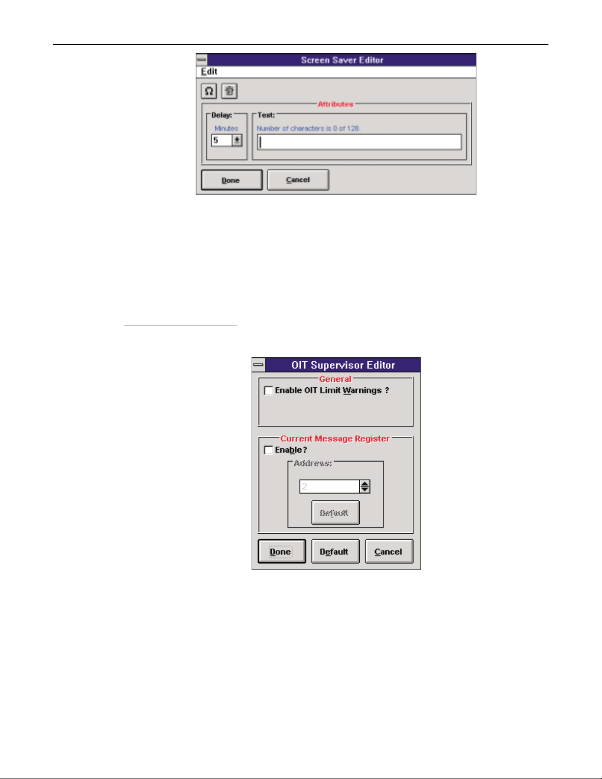
OIT Supervisor Editor
This feature isselected from within theConfiguration Editor and the following screen appears:
The OIT SupervisorEditor allows theenabling or disablingof certain featureson the OIT.
General Group Box:
When the Enable OIT Limit Warnings check box is checked, the OIT displays the high or
low limit for the Register Monitor whose value is being entered out-of-range. Otherwise, the
OIT displays a message indicating that the value being entered is out-of-range.
1010-0089, REV00
Current Message Register Group Box:
When the Enable ? check box is checked, the OIT will place the number of the last message
currently displayed on the OIT into the Current Message Register. This register can then be
used by the PLC to determine which message is shown on the OIT.
Page 25
24 OPERATION
If the Current Message Register is enabled, an address must be specified in the Address text
box. Pressing the Default button, resets the address to the default address which is two
greater than the address set in the Message group box in the Configuration Editor.
The value in the Current Message Register will either be in decimal or BCD format. It
depends on whether the BCD Format check box in the Message group box in the
Configuration Editor is checked.
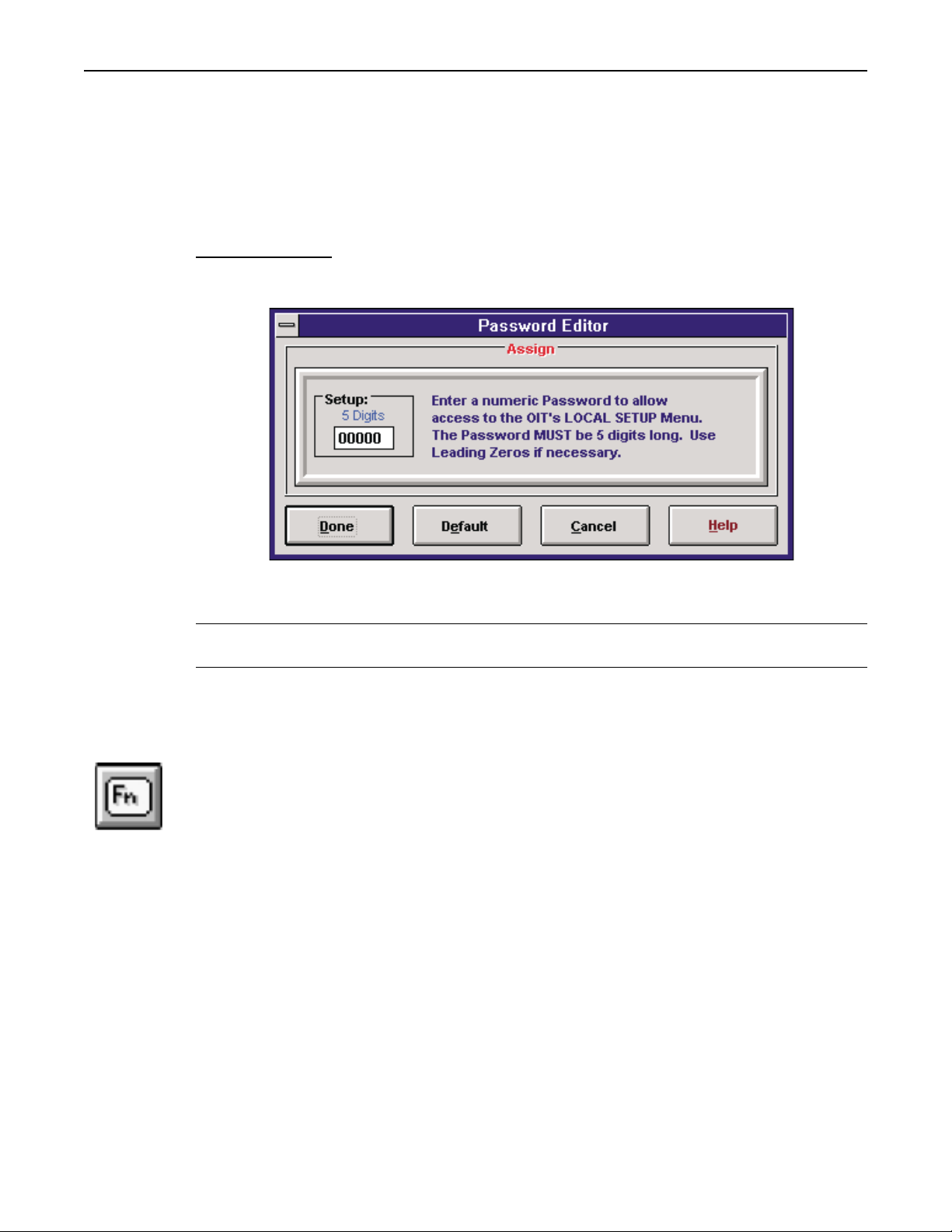
Password Editor
Clicking on theEditor button withinthe Passwords boxwill display thefollowing window:
The setup password is used to gain access to the OIT’s setup menu where local parameters
may be set as well as downloading from the PC.
Note: Make sure you remember the setup password! If you lose it, you will be unable to
download new configuration data or firmware to the OIT!
If the default setting (00000) is selected for the setup password, the operator can enter the
setup menu byentering five 0’s,or using ashortcut which issimply pressing theEnter key.
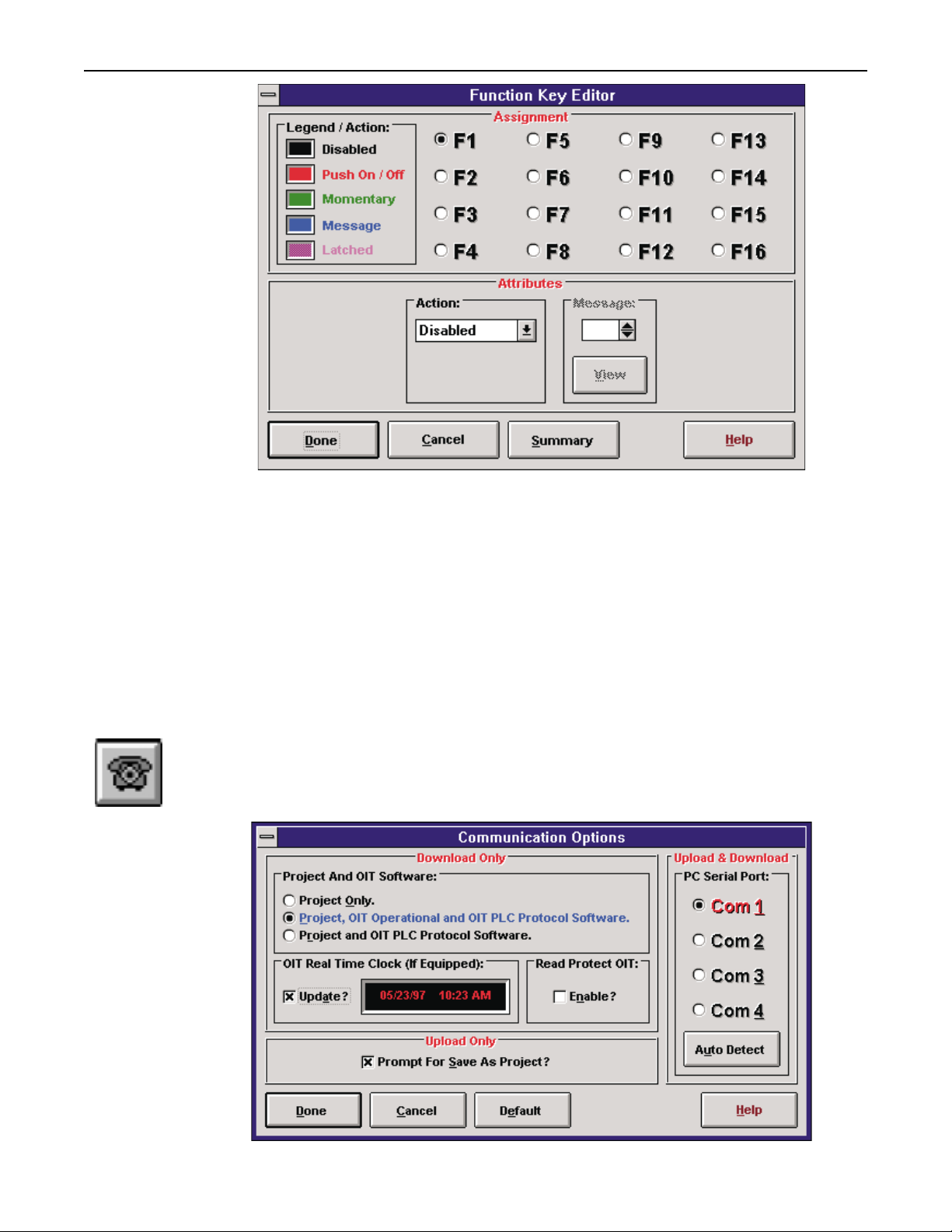
Function Key Editor
The Function KeyEditor button is theshortcut for the Tools/FunctionKey Editor menu item.
The OIT has 12 or 16 programmable function keys, depending on the model. Each key has
the ability to be programmed as disabled, push on-push off, momentary, message display, or
latched. See the MAP Family Operation Manual for a description of each Function Key
mode. Clicking on the Function Keys button will display the function key editor screen:
1010-0089, REV00
Page 26
MAPware 100 User's Guide 25
The Action box is used to dictate the operation of each key. To select a key, use the mouse to click
on a function key in the Status box. The selected function key will darken and its attributes will be
displayed in the Attributes box on the lower half of the screen. Using the mouse, click on the down
arrow in the Action box to display a list of available function key operations. Select one with the
mouse to alter this function key’s operation. As a shortcut, the key can also be configured by
clicking on the appropriate colored square in the Legend/Action box or double clicking over the F
Key orby using the right mouse button. If a function key is configured to display amessage when it
is pressed, the Message box will darken, indicating that it is now valid and will accept data entry.
Set the message number to display using the Message box. The View button will allow you to
browse through the messages to ensure that the proper message has been selected.
Communication Options
The Communication Optionsbutton is theshortcut for theTransfer/Communication Options
menu item. The communication parameters between the MAPware 100 software and the
OIT are configured using the following screen:
1010-0089, REV00
Page 27

26 OPERATION
Notice that COM Ports 1 through 4 are supported, although most machines typically have
COM1 and COM2. The port needs to be set once.
Three options are availableto determinehow theproject informationis to be sent to the OIT. The
Project, Operational, and PLC Protocol option must be used when the OIT is configured for the
first time (default). This selection will send the primary OIT operational software, the PLC
protocol driver, and the project data configuration file to the OIT. The Project and PLC Protocol
option should be used when a previously configured OIT is being configured to attach to a
different PLC. The Project Only option should be used mostoften, after the OIT has been initially
configured and the PLC protocol has already been selected. This option sends the project data
configuration file only and does not send the primary OIT operational software or the PLC
protocol driver. The project data configuration file is everything the system programmer has
created for the OIT using the MAPware 100 software. (For example, messages, function key
configuration, PLC communications parameters, etc.) The Project Only option dramatically
reduces the download time of the OIT. The MAPware 100 software will check to see if the
primary OIT operational software and the PLC protocol driver inthe OIT match what is currently
used in the project and give a warning message if there is a mismatch.
If you select Auto Detect, MAPware 100 will ascertain if the OIT is connected to the
computer correctly and which serial port is attached to the OIT. To use this feature, connect
the OIT to the PC and place the OIT in upload/download mode. MAPware 100 will then
search the PC’s serial communications ports. If an OIT was detected, the serial port will be
set on the Communication Options screen (and saved and restored each time you use
MAPware 100) and the OIT will be reset.
Note: If the Read Protect switch is set then the MAPware will be unable to read from the OIT.
Use caution when using this switch. Note that it is project related and if you set this
switch for the current project, a new project will not have this switch set.
Read from OIT
The Read from OIT button is the shortcut for the Transfer/Read from OIT menu item. The
Read from OIT button allows you to read a project stored in the OIT (refer to the
Communications Options screen). To use this feature, make sure that the OIT is connected to
the PC, is powered up, and that the OIT is in upload/download mode. Select either Transfer
Read from OIT (F11) or the Read from OIT button.
Once selected, the following screen appears:
1010-0089, REV00
Page 28
MAPware 100 User's Guide 27
If you select Options, the Communications Options screen appears.
Note: If you have Prompt for Save As enabled (default), you will be prompted for a file name
to save the project as read from the OIT.
Select OK. If the Prompt for Save As is active, the Save As dialog box will appear.
Note: If the OIT does not have a valid project, the read will terminate. MAPware 100 will then
ascertain if the OIT is read protected. If it is, the read will terminate. Refer to the Read
Protect section for details.
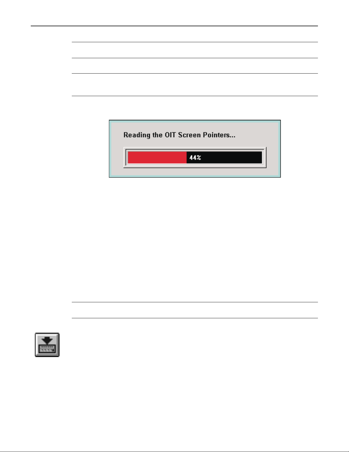
The OIT will now be read by MAPware 100. You can track the status of the read by the “gas
gauge” displayed:
When the read is complete, the OIT will be restarted, and the project you read will be present
on the MAPware 100 screens.
Read Protect
Sometimes it is desirable to read protect the OIT to keep any unauthorized individuals who
have access to MAPware 100 from reading the project stored in the OIT. You can read
protect the OIT in either of two ways:
•
Select the Transfer Read Protect OIT command from the MAPware main menu, under the
Transfer Menu item. When you select this command you must place the OIT in
upload/download mode and insure that the OIT is attached to the PC.
•
Select Read Protect OIT in the Communications Options screen. This switch is project
related. That is, if you select this feature on a particular project, the switch will be set every
time you recall that project. The OIT is read protected as soon as the project is sent to the
OIT.
Note: Once the OIT is read protected, you cannot disable this feature. You may disable this
feature only when a new project is sent to the OIT.
Send to OIT
The Send to OIT button is the shortcut for the Transfer/Send to OIT menu item. This button is
used to actually send a project to the OIT. Before using this command, make sure the OIT is
connected to the correct COM port on the PC. The OIT must be in the local setup menu at the
Download/Upload OIT Project? YES prompt. Select YES by pressing the Enter key on the
OIT. The Computer Communications Mode screen will appear at which time the OIT is ready
to accept information from the PC. The computer candownload the entire project tothe OIT or
the data files only. The entire project would consist of the latest OIT operating code, the latest
PLC protocol driver used by the OIT, and all of the data and screens configured using the
MAPware 100 configuration software. If data files only is selected, the MAPware 100
software will still check the OIT operating code and the PLC protocol driver to ensure that the
1010-0089, REV00
Page 29

28 OPERATION
OIT is using the latest revisions, then proceed to download all of the data and screens created
using the MAPware 100 configuration software. While the OIT internal FLASH EPROM is
being updated, the dialog box that appears will display the percentage of completion.
Depending on how many messages, register monitors, etc. you have programmed into the
project, the download time will vary. Once the project has been downloaded into the OIT, the
configuration of theOIT is permanent; nobatteries are needed to maintain the configuration.
Help
The Help button executes the Windows Help system. Within the help system, you may
search for help on any topic, or read information based on a topic. Keywords have been
entered to make the searching easier on you. At any time, clicking on the Help buttons on a
screen will call up context sensitive help, help about the screen currently displayed, and its
associated features.
OIT/PLC Identification
The information box displays the Maple OIT model currently being programmed on the left
hand side of the screen. The right hand side ofthe information box displays the PLC protocol
which the OIT will use to communicate to the PLC. The OIT programmer should check that
the PLC protocol listed correctly matches the PLC being used before any data screens are
created since all data screens created will be erased if a new PLC protocol is selected. The
center of the information box is used to display the message number of the current message
being edited.
Basic Screen Characteristics
The MAP Family of OITs is line-based instead of screen-based. This means that a message
occupies a single line on the OIT display.
A message screen is used to convey information to the operator. Messages can be text only or
contain PLC register monitors. PLC registers can be placed on the message so that the
operator can see what is happening inside the PLC in real-time. Messages can be chained or
connected to other messages within the system. Chaining allows the OIT programmer to
increase the OIT screen size by creating several pages of messages which are linked to each
1010-0089, REV00
Page 30

MAPware 100 User's Guide 29
other. To enable chaining, click on the Chain check box and enter the message number to
connect to. When the OIT is functioning, the operator presses the Right Arrow key to scroll
through the chained messages.
A message can be displayed in several ways: the PLC may request it, the press of a function
key may display it, or another message may be chained to it.
Message Editor
The message editor is the portion of the screen used to enter information used for the
messages. It is accessed simply by placing the cursor on a portion of the message and
beginning typing. To delete characters from the message, either press the backspace key on
the keyboard or highlight a range of characters and press the delete key on the keyboard. To
highlight a range of characters, use the mouse to move the cursor to one of the desired
characters. Press and hold the left mouse button. Drag the mouse and notice that part of the
message changes color (becomes highlighted). Once the desired characters have been
highlighted, release the left mouse button.
Selected characters and register monitors may be cut, copied, and pasted onto the same
message or other messages. Cutting removes the text or register monitors from the message,
while copying simply makes a copy of the highlighted text and register monitors. After
cutting or copying the desired item, move the cursor to the desired location within the same
message or another message or click on the left mouse button. An outline cursor will appear
on the display. Use the mouse to click on the Paste button on the tool bar. The cut or copied
text will beplaced at the selectedarea of themessage. A right mousebutton menu is available
when the cursor is over the Message Editor area.
Message Scroll Bar
The scroll bar to the right of the message editor is use to move easily between messages
during the editing process. To jump directly to a given screen, use the Edit/Go To Message
menu or press the Control G shortcut key.
General Options Group Box
Line Number (1 to 2)
The Line Number is used to specify which line of the OIT display the message will display
on.
Start-up Message
The startup message is used to select a message which will always be displayed when the
OIT is initialized. Only one messagecan be selected as the startup message. If no message is
selected, then the OIT will initialize and display a blank screen.
Extensions
The Chain feature allows the message being edited to chain to another message specified in
the Message box.
1010-0089, REV00
Page 31

30 OPERATION
OIT Memory Used Group Box
OIT Memory Used is an indicator that displays the amount of memory that has been
consumed. No more configuration data may be stored once the OIT Memory Used shows
100%.
The amount of memory required for a project varies depending upon how the system is set
up. There aren’t really any hard boundaries for how many register monitors may be
programmed. The actual number is determined by how much memory is consumed during
configuration. The reserved memory space is dynamically allocated; that is, messages don’t
all require the same amount of space. Maple Systems has invested a lot of effort in ensuring
that maximum efficiency is attained with the memory that is available. Therefore, the
amount of memory required for a message depends on a number of things: how many
blinking characters there are, how many register monitors there are, and what type of register
monitors are stored on the message. Because there aren’t any pre-defined limits on the
configuration database, the OIT Memory Used was added to the main screen as an indicator
of the amount of remaining free memory.
Message Utilization
From the Tools menu, select Message Utilization (or Control + U). The Message Utilization
screen appears. This screen displays the amount of messages used in the project, their type,
and their location within the project. The screen shows 250 messages at a time. You may
select 1–250 or 251–500.
1010-0089, REV00
Page 32

MAPware 100 User's Guide 31
If you use the mouse, you can click on any of the displayed messages. In the Characteristics
area located at the bottom of the screen, the message you are reviewing will have relevant
characteristics displayed (such as chaining, etc.). The caret will move along with the mouse
click. When you move the mouse over the screen suite, the message you are over is displayed
in red in the lower left corner.
Each of the messages displayed will have a different color, based on the line number. To
view the message, click on the message you want to view, then select the View button. To go
to the message,either double clickon the messageor click andthen press GoTo Message.
1010-0089, REV00
Page 33

32 MAPware 100 User's Guide
TROUBLE SHOOTING
MAPware 100 Does Not Transfer a Project to the OIT
If MAPware 100 halts during a download or indicates that the OIT is not connected:
1. Make sure that the serial cable is connected to the right PC and OIT ports.
2. Make sure that the OIT is powered and is in download mode.
3. Make sure that MAPware 100 is configured for the correct serial port.
4. Check cable connections and pinouts to ensure proper configuration.
5. If all else fails, save your project and then try rebooting your computer.
OIT Screen is Blank and the OIT is Beeping
If the OIT has a blank screen and is beeping, this indicates that an MAPware 100 project was
not completely transferred to the OIT. However, there is nothing wrong with the OIT.
The OIT is in download mode. Simply resend the project from MAPware 100 and the OIT will
restart normally.
The OIT Does Not Attach to the PLC
If the OITis displaying a message indicatingthat it is attemptingto attach to the PLC(and the
attachment successful message never appears), the OIT is not correctly programmed to
communicate with the PLC.
1. Make sure that the serial cable is connected to Port 1 on the OIT.
2. Look at your MAPware 100 project. The PLC selected using Start New Project is
displayed in the right hand corner of the screen. If the PLC selected is incorrect you
must start a new project. Refer to Step 3.
1010-0089, REV00
MAPware 100 Main Screen
Page 34

TROUBLE SHOOTING 33
3. Power is not being supplied to the PLC. Check power supply and cabling to ensure a
successful power connection.
4. The default values in the Configuration Editor may not be appropriate for the
requirements of the PLC you are using. The default values are designed to work with the
chosen PLC in most cases, but may not work in all cases, especially if ladder logic values
have been changed drastically. Adjust the Configuration Editor parameters and resend the
project to the PLC. If this does not work, refer to the appropriate Maple Systems PLC
Protocol Guide for more information or contact Maple Systems Technical Support at
425-486-4477.
1010-0089, REV00
 Loading...